- About This Guide
- Cisco Voice Switch Service Module Introduction
- Cisco Voice Switch Service Module Description
- Configuring VoIP Switching Applications
- Configuring Switches for AAL2 Trunking Applications
- Configuring VXSM Features
- VXSM as a Signaling Gateway
- VXSM as a Transcoding Gateway
- Implementing Lawful Intercept on VXSM
- Configuring Lawful Intercept Support
- Loading and Upgrading VXSM Code Images
- VXSM Troubleshooting
- Media Gateway Clocking
- Voice Switch Service Module Physical Description
- VXSM Firmware Images
- VXSM Card Applications
- VXSM Codec Templates
- Switching Operation—VoIP
- Switching Features
- Virtual Media Gateways
- Support for H.248 Congestion and Overload
- Backhauling Signaling Channels
- VoIP Security Features
- Communications Assistance for Law Enforcement Act Support
- E911 Emergency Services Support
- Announcements Feature
- Voice Quality Monitoring Feature
- Busy Line Verification and Operator Interruption
- Transcoding Feature
Cisco Voice Switch Service Module Description
This chapter describes:
•![]() The features and functions of the Cisco Voice Switch Service Module (VXSM) card set.
The features and functions of the Cisco Voice Switch Service Module (VXSM) card set.
•![]() The VXSM application as a media gateway in a Cisco MGX 8880 or Cisco MGX 8850.
The VXSM application as a media gateway in a Cisco MGX 8880 or Cisco MGX 8850.
Voice Switch Service Module Physical Description
VXSM consists of a full-height front card and a half-height back card or cards. The front card includes a large daughter card on which the digital signal processors (DSPs) are installed. The front card and daughter card are installed as one assembly and require only 1 slot. The complement of cards is as follows.
Voice Switch Service Module Front Cards
Three types of front card are supported (see Figure 2-1):
•![]() MGX_VXSM_155—A full-height card used with OC-3 back card ports.
MGX_VXSM_155—A full-height card used with OC-3 back card ports.
•![]() MGX_VXSM_48_T1/E1—A full-height card used with T1/E1 back card ports.
MGX_VXSM_48_T1/E1—A full-height card used with T1/E1 back card ports.
•![]() MGX_VXSM_6_T3/E3—A full-height card used with T3/E3 back card ports.
MGX_VXSM_6_T3/E3—A full-height card used with T3/E3 back card ports.

Note ![]() In releases 5.4, 5.5 and 5.6, the MGX_VXSM_6_T3/E3 front card supports T3 only.
In releases 5.4, 5.5 and 5.6, the MGX_VXSM_6_T3/E3 front card supports T3 only.
Voice Switch Service Module Back Cards
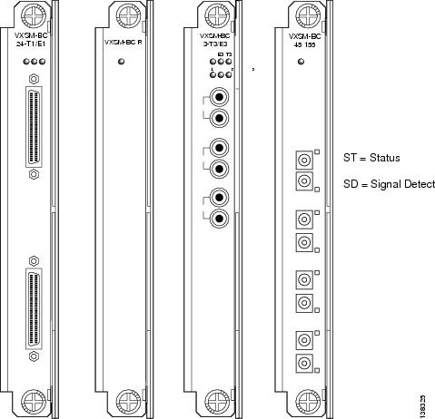
Four types of back card are supported (see Figure 2-2):
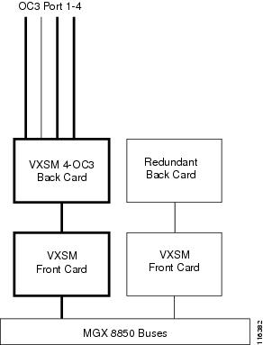
•![]() VXSM_BC_4-155—A half-height card installed in the upper bay (for same card APS SONET line protection, a second back card can be installed in the lower bay). This card provides 4 OC-3 ports.
VXSM_BC_4-155—A half-height card installed in the upper bay (for same card APS SONET line protection, a second back card can be installed in the lower bay). This card provides 4 OC-3 ports.
•![]() VXSM_BC_3-T3—A half-height card. Two cards are used as a pair. One card is installed in the upper bay and one in the lower bay (providing a total interface for 6 T3/E3 lines).
VXSM_BC_3-T3—A half-height card. Two cards are used as a pair. One card is installed in the upper bay and one in the lower bay (providing a total interface for 6 T3/E3 lines).
•![]() VXSM_BC_24-E1/T1—A half-height card. Two cards are used as a pair. One card is installed in the upper bay and one in the lower bay (providing a total interface for 48 T1/E1 lines).
VXSM_BC_24-E1/T1—A half-height card. Two cards are used as a pair. One card is installed in the upper bay and one in the lower bay (providing a total interface for 48 T1/E1 lines).
Note ![]() Each 24 T1/E1 back card is equipped with two 50-pin connectors: one for transmit signals, and one for receive signals. Connect T1 and E1 lines through customer-supplied patch panels. Examples are:
Each 24 T1/E1 back card is equipped with two 50-pin connectors: one for transmit signals, and one for receive signals. Connect T1 and E1 lines through customer-supplied patch panels. Examples are:
Ortronics 24-port Patch Panel: Part Number 808-044990
Ortronics 48-port Patch Panel: Part Number 808-045368
•![]() VXSM_BC_R—This is a redundant back card (no lines).
VXSM_BC_R—This is a redundant back card (no lines).
MGX Chassis
VXSM cards can be installed in either a Cisco MGX 8880 or a Cisco MGX 8850 chassis (Cisco MGX 8880 series chassis with VXSM front cards, see Figure 2-1 and for back cards, see Figure 2-2). The differences between these chassis are as follows.
•![]() Physically, the two chassis are card-compatible. The same control and service module cards can be installed in either chassis. However, the MGX 8880 supports only those cards that are used in media gateway applications. These are PXM-45c, VXSM, AXSM, and PRM-XF cards.
Physically, the two chassis are card-compatible. The same control and service module cards can be installed in either chassis. However, the MGX 8880 supports only those cards that are used in media gateway applications. These are PXM-45c, VXSM, AXSM, and PRM-XF cards.
•![]() The MGX 8880 chassis is smaller in height than the MGX 8850. Three MGX 8880 chassis can be installed in one 7-foot rack (as opposed to two for the MGX 8850).
The MGX 8880 chassis is smaller in height than the MGX 8850. Three MGX 8880 chassis can be installed in one 7-foot rack (as opposed to two for the MGX 8850).
•![]() An RCON card is an integral part of the MGX 8880 chassis.
An RCON card is an integral part of the MGX 8880 chassis.
•![]() The RCON card cannot be used in the MGX 8850 chassis.
The RCON card cannot be used in the MGX 8850 chassis.
Note ![]() The RCON card (Redundancy Connector) is a small assembly. It is installed in the top of the rear shelves spanning slots 1 to 6. An optional second RCON card can be installed in the bottom shelves and spans slots 7 to 12. Back cards connect to the RCON which in turn connects to the midplane of the MGX 8880 chassis. The RCON provides redundant paths for the back cards and its use is described in the Redundancy section of this chapter.
The RCON card (Redundancy Connector) is a small assembly. It is installed in the top of the rear shelves spanning slots 1 to 6. An optional second RCON card can be installed in the bottom shelves and spans slots 7 to 12. Back cards connect to the RCON which in turn connects to the midplane of the MGX 8880 chassis. The RCON provides redundant paths for the back cards and its use is described in the Redundancy section of this chapter.
Figure 2-1 Cisco MGX 8800 Series Chassis with VXSM Front Cards
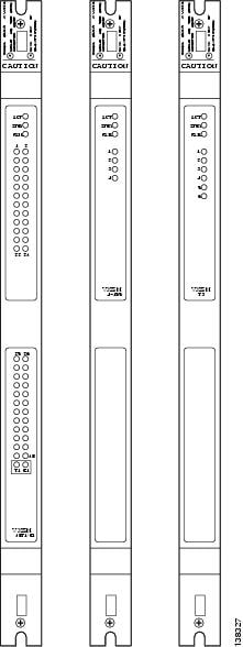
Figure 2-2 Cisco MGX 8800 Series Chassis with VXSM Back Cards
The transmit and receive pin assignments on the 24 T1/E1 back card appear in Table 2-1 and Table 2-2.
Card Slots
In an Cisco MGX 8880 chassis or an Cisco MGX 8850 chassis, VXSM cards can be installed in slots 1 through 6 and 9 through 14. Slots 7 and 8 are reserved for PXM-45c cards.
The 12 slots (1 through 6 and 9 through 14) are available for VXSM cards. However, all installed AXSM, MPSM, and RPM-XF cards also share these slots.
Slots 15 and 16 are reserved for SRM cards. These cards are typically not used in an Media Gateway application and the slots must remain empty.
When 1:1 redundant VXSM front cards are configured, the redundant pair must be installed in adjacent slots (for example, slots 1 and 2 or slots 9 and 10).
VXSM Firmware Images
VXSM is available with two versions of firmware: CALEA and non-CALEA:
•![]() CALEA permits the user to configure support for the Communication Assisted Law Enforcement Act (CALEA)
CALEA permits the user to configure support for the Communication Assisted Law Enforcement Act (CALEA)
•![]() Non-CALEA does not permit the user to configure support for the CALEA
Non-CALEA does not permit the user to configure support for the CALEA
The user must specify either CALEA or non-CALEA at the time of order.
Both the CALEA and non-CALEA versions support MGCP, TGCP, and H.248 control protocols but only one at a time.
At the time of installation, user must:
•![]() Choose between either the H.248, MGCP, or TGCP protocol
Choose between either the H.248, MGCP, or TGCP protocol
•![]() Specify the codec template as either TGW/Wireline (default) or TWGW2 or FMC or cable as appropriate
Specify the codec template as either TGW/Wireline (default) or TWGW2 or FMC or cable as appropriate
To execute these choices, use the setrev command on the PXM after the VXSM cards are installed. The user specifies the VXSM card (by slot number), the gateway controller protocol, and codec template. Then, the selected firmware and DSP images load onto the VXSM card. The non selected protocol commands and codec functions are disabled.
Note ![]() VXSM supports upgrade of non-CALEA to CALEA firmware.
VXSM supports upgrade of non-CALEA to CALEA firmware.
VXSM Card Applications
Regardless of the firmware image that is installed, VXSM cards can be configured to perform the following four types of applications:
•![]() Media gateway with VoIP switching
Media gateway with VoIP switching
•![]() Media gateway with non switching trunking
Media gateway with non switching trunking
•![]() Signaling gateway
Signaling gateway
•![]() Transcoding gateway
Transcoding gateway
One VXSM card can be configured to perform all four applications concurrently in which TDM lines are assigned to the specific applications.
The signaling and transcoding types of media gateway applications are described in:
•![]() VXSM as a Transcoding Gateway
VXSM as a Transcoding Gateway
The following sections describe the two types of media gateway applications.
VXSM Codec Templates
Codecs use different algorithms to encode analog voice into digital bit streams and have different bit rates, frame sizes, and coding delays associated with them. Codecs also differ in the amount of perceived voice quality they achieve. For more information on codecs see, "Codec Support for H.248, MGCP, and TGCP Signaling" section
VXSM transcoding supports four codec templates:
Support for Alternative Codec String
Release 5.6.10 introduces support for alternate strings for existing codecs. Presently VXSM supports only standard codec strings such as PCMU, G.711u, and so on. This feature enables VXSM to use the alternate strings in addition to the existing standard strings. The following call control protocols support this feature:
•![]() H.248
H.248
•![]() MGCP
MGCP
The feature supports these codec templates:
–![]() TGW and Wireline: Supports G.711, G.723, G.723.1a, G.726, G.729, G.729A, and Clear Channel.
TGW and Wireline: Supports G.711, G.723, G.723.1a, G.726, G.729, G.729A, and Clear Channel.
–![]() Cable: Supports G.711 and iLBC.
Cable: Supports G.711 and iLBC.
–![]() TGW2: Supports G.711, G.726, G.729A, iLBC, and Clear Channel.
TGW2: Supports G.711, G.726, G.729A, iLBC, and Clear Channel.
–![]() FMC: Supports G.711, G.726, G.729A, AMR-NB, GSM-EFR, and Clear Channel.
FMC: Supports G.711, G.726, G.729A, AMR-NB, GSM-EFR, and Clear Channel.
These commands were added to the feature:
–![]() cnfcodecstring: Specifies the codec string. You can specify three strings for a particular codec using this command. The existing standard codec strings and duplicate strings are not configurable.
cnfcodecstring: Specifies the codec string. You can specify three strings for a particular codec using this command. The existing standard codec strings and duplicate strings are not configurable.
–![]() dspcodecstring: Displays the codec strings for a particular codec.
dspcodecstring: Displays the codec strings for a particular codec.
–![]() dspcodecstrings: Displays the codec strings for all codecs.
dspcodecstrings: Displays the codec strings for all codecs.
Switching Operation—VoIP
VXSM support two methods for routing voice calls:
1. ![]() A switching method for VoIP applications
A switching method for VoIP applications
2. ![]() A non switching method for AAL2 trunking applications
A non switching method for AAL2 trunking applications
The difference is how the internal and external connections are configured. VXSM can support AAL2 trunking, AAL5 trunking, and VoIP concurrently on the same VXSM card.
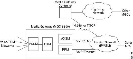
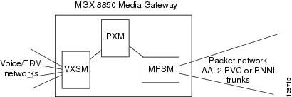
In switching operations, VXSM switches voice traffic between the conventional TDM voice network and the packet network under the control of a media gateway controller (MGC). VXSM and the MGC must have IP connectivity and use the H.248 (MEGACO) protocol, MGCP protocol, or the TGCP protocol to communicate.
Using one of these protocols, VXSM and the MGC communicate at each stage of the call setup and call tear down processes (on/off hook, dial tone, dialing, hang-up). At each stage, the MGC instructs VXSM how to perform the next step.
During call setup, a bearer circuit is set up across the packet network. This bearer circuit is used to establish IP connectivity for the voice traffic between the calling and called media gateways.
VXSM uses either an AXSM card or an RPM-XF card as its interface to the packet network:
•![]() AXSM card—Communication between the gateways is voice over ATM communication using AAL5 PVCs.
AXSM card—Communication between the gateways is voice over ATM communication using AAL5 PVCs.
•![]() RPM-XF card—Communication between gateways is voice over IP communication using a gigabit Ethernet network.
RPM-XF card—Communication between gateways is voice over IP communication using a gigabit Ethernet network.
Figure 2-3 shows the switching process.
Figure 2-3 Switching Operation Block Diagram
Switching Features
Switching operation supports the following features.
Time-Division Multiplexing Network Side
Interfaces
4 OC-3/STM-1, 6 T3/E3, and channelized 48 T1/E1
Companding
Mu law and A-law conversion
Configurable mu law and A-law endpoints on network side
Echo Cancellation
Echo removal on PCM samples using proprietary algorithm 8, 16,24,32,64, or 128 ms tails
Tones
Detects V.25 (with and without phase reversal) and V.8 signals or V.21 preamble or CNG tone to discriminate between voice, fax, and data calls
Upspeed to PCM upon fax/modem detection
The DSP module is capable of detecting DTMF tones while processing voice signals and transporting them in or out of band. (RFC 2833 and I.366.2 compliant)
Support for SS7 continuity tone for 2 and 4 wire circuits
PRI Backhaul
In applications where ISDN D channel signaling line are connected to VXSM, the VXSM can be configured to extract the layer 3 (Q.931) packets and backhaul them to the media gateway controller. PRI backhaul supports RUDP (Reliable UDP) and SCTP (Stream Control Transport Protocol) as transport protocols.
Network Bypass
For calls that originate and terminate on lines on the same VXSM card or the same media gateway, VXSM can be configured so that the call is routed within the media gateway and does not use IP or packet network resources. This feature operates with H.248 protocol only.
Busy Line Verification and Operator Interrupt
A caller can request that an operator check a called station to ascertain whether or not it is busy. This feature permits the operator to interrupt an ongoing call and relay a message to the called party.
Packet Network Side
ATM
Real-time protocol (RTP)
AAL 5 PVCs for bearer circuits
Codecs
G.711, G.726-32K, G.729a, G.729ab, and G.clear (clear channel).
Connection Admission Control
For connection admission control (CAC), VXSM maintains information on available/used bandwidth on bearer virtual circuits. For PVC calls, before a call is admitted, a bandwidth check (based on code, packetization period, VAD) is made against the available PVC bandwidth. The result determines if the call is accepted or rejected.
Packetization Period
The codec packetization period is configurable up to 80 ms.
The VDB codec packetization period is configurable from 10 ms to 30 ms in 10 ms increments.
Jitter
Removes arrival time jitter from the incoming packet stream. Jitter buffer can manage up to 135 ms.
Silence Suppression
Uses voice activity detection (VAD) on bearer circuits to detect silence and suppress the transmission of cells containing silence. VAD is applicable on codecs G.711, G.723.1-H, G.723.1-L, G.723.1A-H, G.723.1A-L, G.726, G729a, G.729b, and G.729ab
H.248 Transparent IP-IP Connections
When an H.248 IP-IP connections is created in which the codec and packetization period are the same for each end of the bearer leg, VXSM can be configured to establish the connection in "transparent" mode. Because no transcoding of the bearer stream is necessary in transparent mode, transcoding is eliminated thus permitting bit transparency as well as the better bearer latency (less transit delay over the IP-IP connection). In the transparent mode, the SSRC (Synchronization SouRCe) is also preserved across the connection.
Differentiated Services
VXSM provides support for the quality of service (QoS) Differentiated Service feature known as DiffServ. DiffServ permits devices at the edge of the network to specify the contents of the Type of Service (ToS) field in the IPv4 header as a differentiated services point code. This point code can then be used by routers in the network to determine per hop behavior (PHB).
VoIP Security
VXSM provides a set of security features for the protection of bearer and signaling traffic in switching VoIP applications using TGCP. In particular, these features are designed to meet PacketCable standards.
E911 Emergency Services
VXSM supports an emergency services feature in which 911 dialed emergency calls are automatically directed to an E911 tandem switch and then onto a public safety answering point (PSAP).
Virtual Media Gateways
For H.248 switched applications, a VXSM card has the capability of being partitioned into a number of Virtual Media Gateways (VMGs) where each VMG is a logical entity residing within a physical VXSM card. This feature can be used in applications in which a single Media Gateway Controller (MGC) does not have the capacity to control one VXSM gateway. By partitioning the VXSM card into several VMGs, the control of VXSM's physical and ephemeral terminations can be distributed among several Media Gateway Controllers (one physical termination per MGC).
The VXSM Virtual Media Gateway feature permits a VXSM card to be partitioned into a maximum of 12 virtual gateways. Each of the virtual gateways appears to the MGC as a complete media gateway client and is identified by its own unique domain name. If one VMG goes out of service, the services provided by other VMGs are not affected. VXSM will clear call related data only for the VGM going out of service.
Figure 2-4 shows a VXSM card partitioned into four virtual gateways.
Figure 2-4
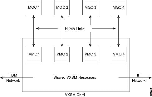
VXSM with Four Virtual Media Gateways
Virtual Gateways and H.248 Terminations
Physical terminations are statically partitioned among VMGs. Ephemeral terminations belong to the VMG whose controlling MGC creates them. One termination belongs to one, and only one, VMG. The finest granularity at which physical terminations are allocated to a VMG is at the T1/E1 level. Individual T1/E1 trunks may be added to a VMG, in any order.
The user must first create the required number of VMGs and then allocate terminations to their VMGs as they are provisioned. If VXSM is not to be partitioned, then the user creates only one VMG and associates all physical terminations with it.
Virtual Gateway Redundancy
VXSM supports redundancy at the physical gateway (VXSM card) level. One VXSM card acts as active for all of its VMGs, and another VXSM card acts as standby for all of its VMGs. In case of a failure, a physical gateway (VXSM card) level switchover is performed in which all VMGs on the active card are switched over to the standby card (Figure 2-5).
Virtual Media Gateway Domain Names
For systems using call control protocols other than H.248 (for example, MGCP), VXSM operates as a single media gateway and is assigned a single domain name.
For systems using the H.248 call control protocol, a VXSM card is configured as a number of virtual media gateways in the range of 1 to 12. Each virtual media gateway must be assigned it own unique domain name using the VmgwDomainName parameter in the addh248assoc. Once created it can be changes with the cnfh248mg command. This parameter permits the user to provision a domain name as a character string of up to 64 characters.
Both the addh248assoc and the cnfh248mg command also have a port number and a mIdUsePort parameter. The mIdUsePort parameter determines whether the port number will be used in conjunction with the domain name in the mld field of H.248 messages.
For example, if the VmgwDomainName parameter is used to assign the domain name of VMGW001 and the port number is specified as 2848, the mId of the virtual media gateway is:
VMGW001 if mIdUsePort is set to No port number, or
VMGW001:2848 if mIdUsePort is set to Use port number.
Figure 2-5
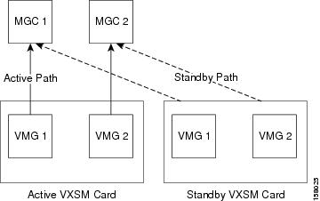
Virtual Gateway Redundancy—VXSM Card Level
Support for H.248 Congestion and Overload
VXSM supports the H.248.10 Congestion Control Package, and the H.248.11, Overload Control Package.
The H.248.10 MG Congestion Control Package is used to exchange congestion information between the MG and the MGC. VXSM reports congestion events to the MGC if congestion control has been enabled and MG detects a congestion event.
The H.248.11 MG Overload Control feature protects VXSM from processing overload that prevents the timely execution of H.248.1 transactions. MG Overload happens when the utilization of resources crosses a threshold and MG is close to being unable to respond to MGC transactions in a sufficiently timely manner to avoid the calling customer abandoning the call in setup.
When the H.248 overload feature is enabled, VXSM monitors and detects gateway overload condition. Upon detection of an overload condition, VXSM sends a Notify to the MGC when it receives an ADD command, in this way the MGC can adjust the calling rate to bring MG out of overloaded condition.
Backhauling Signaling Channels
For applications in which the signaling lines or channels are connected directly to VXSM, VXSM can be configured to relay the signaling messages to the Media Gateway Controller (MGC) for call control processing. This backhauling relay function consists of extracting the level 3 signaling message from the level 2 transport protocol, encapsulating it into the IP protocol stack, and relaying it onto the MGC.
To meet the requirements of various service provider networks, VXSM support a number of TDM network-side and the IP network-side protocol stacks for this purpose. VXSM supported backhaul protocols are shown in Table 2-4.
|
|
|
|---|---|
ISDN D-channel (Q.931, Q.921 |
UDP, RUDP |
ISDN D-channel (Q.931, Q.921) |
SCTP, IUA |
•![]() SCTP—Streaming Control Transmission Protocol
SCTP—Streaming Control Transmission Protocol
•![]() RUDP—Reliable UDP
RUDP—Reliable UDP
•![]() IUA—ISDN Q921-User Adaptation
IUA—ISDN Q921-User Adaptation
ISDN/RUDP Backhauling
When D channels of ISDN PRI lines are connected to the TDM side of the VXSM card, VXSM can be configured to extract the Layer 3 (Q.931) frames from the ISDN stream and pass (backhaul) them to the gateway controller. Likewise, Q.931 frames received from the gateway controller can be encapsulated into Layer 2 (LAPD Q.921) frames and transmitted over the appropriate D channel ISDN lines on the TDM side. This function is known as PRI Backhaul. Both T1 and E1 lines are supported.
The backhaul feature can be configured as either:
•![]() Non-fault tolerant—Using one gateway controller, or
Non-fault tolerant—Using one gateway controller, or
•![]() Fault-tolerant—Using two gateway controllers; one active and one backup
Fault-tolerant—Using two gateway controllers; one active and one backup
Both configurations can be combined with 1:1 VXSM card redundancy. Automatic switchover is supported for both gateway controller and VXSM card failures.
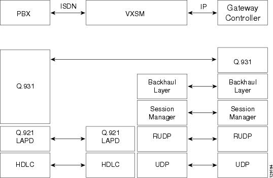
On the TDM side, ISDN PRI standards protocols are used. The Q.931 signaling frames are encapsulated in Q.921 (LAPD) frames and transported as High Level Data Link Control (HDLC) frames. The HDLC and Q.921 layers are terminated at the VXSM.
For communication between VXSM and the media gateway controller the protocol stack is based upon the Cisco proprietary session manager and RUDP (reliable UDP).
Communication between the VXSM and the gateway controller is session based. One session set must be established. The session set contain one or two session groups (one for non-fault tolerant or two for fault tolerant configurations). Each session group can support up to four RUDP sessions.
Figure 2-6 shows the protocol stacks for ISDN/ RUDP.
Figure 2-6 ISDN Backhaul Protocols Using RUDP
ISDN/SCTP Backhauling
When D channels of ISDN PRI lines are connected to the TDM side of the VXSM card, VXSM can be configured to extract the layer three (Q.931) frames from the ISDN stream and pass (backhaul) them to the gateway controller. Likewise, Q.931 frames received from the gateway controller can be encapsulated into Layer 2 (LAPD Q.921) frames and transmitted over the appropriate D channel ISDN lines on the TDM side. This function is known as PRI backhaul. E1 lines only are supported.
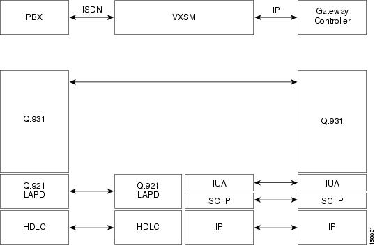
On the TDM side, ISDN PRI standards protocols are used. The Q.931 signaling frames are encapsulated in Q.921 (LAPD) frames and transported as High Level Data Link Control (HDLC) frames. The HDLC and Q.921 layers are terminated at the VXSM.
For communication between VXSM and the media gateway controller, the protocol stack is based upon the Streaming Control Transmission Protocol (SCTP) and the ISDN Q921-User Adaptation (IUA) layer.
SCTP is a reliable transport protocol operating on top of a connectionless packet network such as IP. It offers network-level fault tolerance through supporting of multihoming at either or both ends of an association, congestion avoidance, and resistance to flooding.
Figure 2-7 shows the protocol stacks for ISDN/ SCTP.
Figure 2-7 ISDN Backhaul Protocols Using SCTP
VoIP Security Features
VXSM provides a set of security features for the protection of bearer and signaling traffic in switching VoIP applications using TGCP. In particular, these features are designed to meet PacketCable standards.
RTP and RTCP bearer streams can be protected across an IP network through the use of encryption and authentication algorithms that are applied to the bearer payloads.
The specific security algorithms that are used for any particular call are negotiated during call setup (using TGCP) between the two ends (for example, media terminal adapters) with the media gateway controller acting as a mediator in the process. The signaling links between the media gateways and the media gateway controllers are protected using Internet Security (IPSec and IKE) protocols.
When the algorithms agree, they are used to secure the voice payload.
Note ![]() Signal and bearer security are supported on both the CABLE and TGW firmware images. Signal security (IPSec) operates with either H.248 or xGCP. Bearer security operates with xGCP only.
Signal and bearer security are supported on both the CABLE and TGW firmware images. Signal security (IPSec) operates with either H.248 or xGCP. Bearer security operates with xGCP only.
Figure 2-8 shows the protection in effect for a PacketCable call between two Media Terminal Adapters (MTA).
Figure 2-8 Signal and Bearer Security
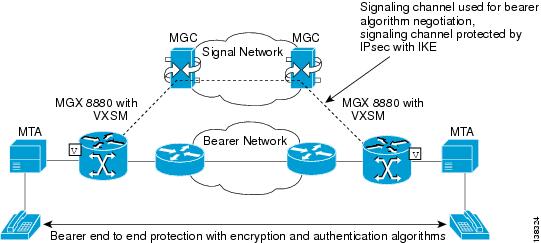
Note ![]() For calls in which one end of the bearer path partially uses public switched telephone system (PSTN), the security extends only to the gateway entity that interfaces to the PSTN.
For calls in which one end of the bearer path partially uses public switched telephone system (PSTN), the security extends only to the gateway entity that interfaces to the PSTN.
Signal Security
VXSM supports protection of the signaling channel through the use of IP Security (IPSec) and Internet Key Exchange (IKE) protocols.
The signaling channel (TGCP) is used to negotiate cipher suites (algorithms) that are to be used on the bearer channel. However, the signaling channel must be capable of protection.
1. ![]() IKE is used to exchange IPSec Security Associations (SA) and this function is performed in two phases. In the first phase the two IKE peers are authenticated.
IKE is used to exchange IPSec Security Associations (SA) and this function is performed in two phases. In the first phase the two IKE peers are authenticated.
2. ![]() The IPSec SAs are negotiated with keys derived from the first phase.
The IPSec SAs are negotiated with keys derived from the first phase.
3. ![]() When the IPSec SAs are authenticated, the signaling stream can be encrypted. IPSec supports two protocols:
When the IPSec SAs are authenticated, the signaling stream can be encrypted. IPSec supports two protocols:
–![]() Authentication Header (AH)
Authentication Header (AH)
–![]() IP Encapsulating Security Payload (ESP)
IP Encapsulating Security Payload (ESP)
IPSec supports two modes:
–![]() Transport mode—Protects the entire transport payload
Transport mode—Protects the entire transport payload
–![]() Tunnel mode—Protects the IP packet by encapsulating it inside another IP packet
Tunnel mode—Protects the IP packet by encapsulating it inside another IP packet
The following IPSec features are supported by VXSM:
•![]() Protocols
Protocols
•![]() ESP
ESP
•![]() Modes
Modes
•![]() Transport and tunnel
Transport and tunnel
Bearer Security
Each VXSM is configured by the user (CLI) to include a table of permissible cipher suites where a cipher suite is a record containing one encryption algorithm, one authentication algorithm and a preference.
When a call is originated, setting up security for the call is accomplished in two phases:
1. ![]() First, using TGCP, the MTAs and media gateways at each end of the call exchange their lists of permissible cipher suites.
First, using TGCP, the MTAs and media gateways at each end of the call exchange their lists of permissible cipher suites.
2. ![]() An acceptable cipher suite is then negotiated. This negotiation is carried out for both RTP and RTCP bearer streams. The following algorithms are supported in VXSM:
An acceptable cipher suite is then negotiated. This negotiation is carried out for both RTP and RTCP bearer streams. The following algorithms are supported in VXSM:
RTP encryption:
•![]() RTP_AES
RTP_AES
•![]() RTP_ENCR_NULL
RTP_ENCR_NULL
RTP authentication:
•![]() RTP-MMH2
RTP-MMH2
•![]() RTP_MMH4
RTP_MMH4
•![]() AUTH_NULL
AUTH_NULL
RTCP encryption:
•![]() AES_CBC
AES_CBC
•![]() RTCP_ENCR_NULL
RTCP_ENCR_NULL
RTCP authentication:
•![]() HMAC-SHA1-96
HMAC-SHA1-96
•![]() RTCP_AUTH_NULL
RTCP_AUTH_NULL
Note ![]() If the negotiation results is one or both of the NULL algorithms, this effectively turns off the security function for each NULL algorithm.
If the negotiation results is one or both of the NULL algorithms, this effectively turns off the security function for each NULL algorithm.
3. ![]() When the cipher suites are agreed upon, the bearer path is set up and the call can be established. The negotiated algorithms are applied to the RTP and RTCP streams respectively.
When the cipher suites are agreed upon, the bearer path is set up and the call can be established. The negotiated algorithms are applied to the RTP and RTCP streams respectively.
Encryption algorithms:
•![]() ESP_3DES
ESP_3DES
•![]() ESP_NULL
ESP_NULL
Authentication algorithms:
•![]() HMAC_MD5-96
HMAC_MD5-96
•![]() HMAC_SHA-1-96
HMAC_SHA-1-96
Communications Assistance for Law Enforcement Act Support
VXSM provides support for Communications Assistance for Law Enforcement Act (CALEA) intercepted calls. The CALEA feature functions only in switching applications using the TGCP gateway control protocol. For more information, see "Implementing Lawful Intercept on VXSM" section.
During call setup, the media gateway controller uses the TGCP commands of CRCX and MDCX with CALEA parameters to signify that a call is subject to CALEA surveillance. During a CALEA call, the VXSM sends a duplicate of the call contents to a TGCP defined CALEA server.
VXSM supports up to 60 concurrent CALEA calls. Statistics collection for CALEA streams is not supported.
Note ![]() The VXSM firmware image is available in two versions: a CALEA version and a non-CALEA version. The version must be specified at the time of order.
The VXSM firmware image is available in two versions: a CALEA version and a non-CALEA version. The version must be specified at the time of order.
E911 Emergency Services Support
VXSM supports an emergency services feature in which 911 dialed emergency calls are automatically directed to an E911 tandem switch and then onto a Public Safety Answering Point (PSAP).
Enhanced 911 (E911) is a Federal Communications Commission (FCC) initiative to increase public safety by the deployment of a nationwide, seamless communications system for emergency services that includes the provision of location information for wireless 911 calls.
The E911 feature on VXSM primarily supports Packet Cable applications, and is implemented using the packet cable specified MO (MF OSS) package in the TGCP protocol. The E911 feature is shown in Figure 2-9.
Figure 2-9 VXSM E911 Feature
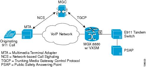
1. ![]() When a 911 call is initiated by the caller, the MGC identifies the appropriate E911 Tandem switch and informs VXSM to set up a call to that switch. The communication between the MGC and VXSM is through TGCP (although MGCP is supported also) using the MF FGD operator services package (MO) protocol. The supported codes within this package are shown in Table 2-5.
When a 911 call is initiated by the caller, the MGC identifies the appropriate E911 Tandem switch and informs VXSM to set up a call to that switch. The communication between the MGC and VXSM is through TGCP (although MGCP is supported also) using the MF FGD operator services package (MO) protocol. The supported codes within this package are shown in Table 2-5.
2. ![]() After the call is made, conversation between the caller and the PSAP operator takes place.
After the call is made, conversation between the caller and the PSAP operator takes place.
3. ![]() The call is then terminated.
The call is then terminated.
4. ![]() The PSAP initiates a call back to establish the validity of the caller. When validated, the 911 process is complete.
The PSAP initiates a call back to establish the validity of the caller. When validated, the 911 process is complete.
The E911 feature is supported on all versions of VXSM cards, but only T1 circuits are supported.
If redundant hardware has been configured, active E911 calls are preserved during a switchover in the event of a failure.
Announcements Feature
In switching applications (H.248 media gateway control protocol only), VXSM includes an announcement feature in which pre-recorded announcements can be played on a voice channel under the control of the MGC. A set of announcement files is maintained on an announcement server:
1. ![]() When an announcement is to play, the MGC uses the announcement package in the H.248 protocol to instruct VXSM to play the announcement.
When an announcement is to play, the MGC uses the announcement package in the H.248 protocol to instruct VXSM to play the announcement.
If the announcement has:
–![]() Been previously cached by VXSM, the announcement is played out of cache.
Been previously cached by VXSM, the announcement is played out of cache.
–![]() Not been previously cached by VXSM, VXSM uses TFTP to download the file from the announcement server, cache it, and play the announcement.
Not been previously cached by VXSM, VXSM uses TFTP to download the file from the announcement server, cache it, and play the announcement.
Announcement files:
–![]() Must be in PCM format and no more than 30 second in play-out duration (this represents a file size of approximately 240 kilobytes). When a file is downloaded from the announcement server, it is stored in a cache in the VXSM which can hold up to 136 announcements. When cache becomes full, any request for an announcement that is not in cache results in the requested file being downloaded and replacing an existing cached file on a "least recently used" basis.
Must be in PCM format and no more than 30 second in play-out duration (this represents a file size of approximately 240 kilobytes). When a file is downloaded from the announcement server, it is stored in a cache in the VXSM which can hold up to 136 announcements. When cache becomes full, any request for an announcement that is not in cache results in the requested file being downloaded and replacing an existing cached file on a "least recently used" basis.
–![]() Can be configured as permanent, in which case they remain in cache and are never replaced.
Can be configured as permanent, in which case they remain in cache and are never replaced.
2. ![]() In addition to the announcement files and the VXSM cache, the user maintains a list of announcement files on VXSM. This list is in the form of a table, indexed by the announcement number, and it contains the name of the file (with directory path, if applicable) in the TFTP server. It also contains (associated with each file) the default values of the optional parameters that the MGC provides with the "play announcement" signal. The mapping of announcement index number to announcement filename must be maintained both in the VXSM and MGC. The MGC specifies the file index in the signal to indicate which announcement it wants to play.
In addition to the announcement files and the VXSM cache, the user maintains a list of announcement files on VXSM. This list is in the form of a table, indexed by the announcement number, and it contains the name of the file (with directory path, if applicable) in the TFTP server. It also contains (associated with each file) the default values of the optional parameters that the MGC provides with the "play announcement" signal. The mapping of announcement index number to announcement filename must be maintained both in the VXSM and MGC. The MGC specifies the file index in the signal to indicate which announcement it wants to play.
3. ![]() The MGC can specify that the announcement be played in the direction of the caller, or the called party, or both.
The MGC can specify that the announcement be played in the direction of the caller, or the called party, or both.
In the current implementation, no redundancy for announcement is supported.
Note ![]() Only the active VXSM card can communicate to the announcement server. All announcements are downloaded on the active card only.
Only the active VXSM card can communicate to the announcement server. All announcements are downloaded on the active card only.
4. ![]() When a switchover occurs, the newly active card downloads the permanent announcements from the announcement server as soon as it goes active. The dynamic announcements are downloaded on the newly active card on demand.
When a switchover occurs, the newly active card downloads the permanent announcements from the announcement server as soon as it goes active. The dynamic announcements are downloaded on the newly active card on demand.
5. ![]() If a card switches over while playing an announcement, the announcement is not automatically continued on the newly active card. The MGC must explicitly restart the announcement on the newly active card.
If a card switches over while playing an announcement, the announcement is not automatically continued on the newly active card. The MGC must explicitly restart the announcement on the newly active card.
Voice Quality Monitoring Feature
When configured for VoIP switched applications using the H.248 call control protocol, the VXSM Voice Quality Monitoring (VQM) feature provides the ability to monitor, collect, and report voice quality metrics to the Media Gateway Controller and/or the remote Media Gateway. Together, the values of the collected metrics represent a measure of the quality of voice calls transmitted across the network. Service providers can use these metrics to observe and diagnose quality problems and to provide a measure for Service Level Agreements between the provider and its customers.
VXSM supports two methods of performing VQM functions:
1. ![]() RFC3611 VQM—Based upon RFC 3611 metrics
RFC3611 VQM—Based upon RFC 3611 metrics
2. ![]() XNQ VQM—Based upon Extended Network Quality (XNQ) metrics
XNQ VQM—Based upon Extended Network Quality (XNQ) metrics
VXSM can support either of these methods but not both simultaneously. These methods differ in the choice of protocols used to communicate with the remote MG and the MGC and the voice quality metrics that are reported.
RFC 3611 Voice Quality Monitoring
RFC 3611 voice quality monitoring (VQM) uses RTP control protocol extended reports (RTCP XR) VoIP metrics (Figure 2-10).
Figure 2-10 RTCP XR VoIP Metrics Method
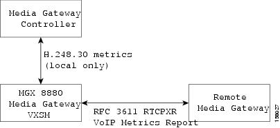
RTCP XR VoIP metrics use the RTP control protocol extended reports (RTCP XR) provision in RFC 3611 to append VoIP metrics reports to the normal RTCP packets. This method also involves the Media Gateway Controller (MGC) through the use of H.248 and the H.248.30 RTCP extended performance metrics packages. The two packages are the RTCP XR base package (rtcpxr) and the RTCP XR burst metrics package (xrbm). The voice metrics defined in these packages are consistent with those defined in the RTCP XR VoIP metrics report block. The media gateway controller is able to set up properties and retrieve statistics (voice-metrics) defined in these packages.
RTCP XR Extended Network Quality Metrics
XNQ voice quality monitoring (VQM) uses RTCP XR extended network quality (XNQ) metrics (Figure 2-11).
Figure 2-11 RTCP XR XNQ Metrics Method
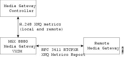
This method uses the RTP control protocol extended reports (RTCP XR) provision in RFC 3611 to append XNQ metrics reports to the normal RTCP packets. This method also involves the media gateway controller (MGC) through the use of the H.248 RTCP extended network quality metrics package. The voice metrics defined in these two packages are consistent with those defined in the RTCP XR XNQ metrics report block. The MGC can set up properties and retrieve statistics (voice-metrics) defined in these packages.
Voice Quality History Reports
VXSM can maintain a history table to generate voice quality history reports to help service providers track their service level agreements. The history report tracks the minimum, maximum and average of the various voice metrics. History table entries are updated only if VQM feature is enabled.
The statistic upload function is used to retrieve the history table periodically. After the voice metric history table is retrieved, the history table is reset.
Voice Quality Alerts
VXSM has the capability of generating voice quality alerts that are reported to the Service Provider in real-time. Voice quality alerts are determined by comparing the measured value of a trigger voice metric to a threshold value. For each voice metric, the threshold values are determined by the following two parameters.
•![]() Voice metric reference value
Voice metric reference value
•![]() Quality alert threshold percentage
Quality alert threshold percentage
When the measured value of a voice metric is worse than the reference value by more than the threshold percentage a voice quality alert is triggered.
VXSM supports one trigger per call at any one time. There is no support for multiple simultaneous triggers in a single call. Each T1/E1 interface can be configured with a different trigger metric. In addition, a default trigger metric can be configured for the whole gateway or a virtual gateway. If neither the gateway nor T1/E1 interface level trigger metrics are configured, no quality alert events or traps are generated and the MGC cannot enable quality alert events.
Voice Quality alert events are reported to the MGC and are based on the H.248 network package. This package allows for multiple thresholds, however, VXSM supports only one. Upon receipt of multiple thresholds, only the last threshold takes effect. If the MGC specifies the alert threshold percentage parameter when enabling a quality alert event, the MGC specified value overrides the threshold value provisioned on VXSM. If MGC does not enable a quality alert event, no alert event notification is sent to the MGC even though a quality alert trap may be generated to the SNMP Manager. After an alert notification is sent to the MGC, VXSM does not re-arm the quality alert event. Thus, a subsequent cross over of the alert threshold does not trigger another alert notification to the MGC.
SNMP voice quality alert traps are also supported. If the voice quality alert event is detected, VXSM can send SNMP quality alert traps to an SNMP Manager if the VQM trap is enabled.
Quality Alerts for Voice Band Data Calls
Upon detection of a modem tone (modem, fax, or TTY), upspeed takes place. Depending on the upspeed method, the Codec may be modified by the gateway or the Call Agent. Further, the jitter and a number of other parameters are re-configured to better handle the VBD mode. After upspeed occurs, the call statistics are reset and the VBD and its associated thresholds trigger and thresholds are downloaded to the DSP.
The reason for resetting the statistics immediately after the upspeed is to avoid using the statistics collected during the voice-phase. VBD connections are usually more sensitive to frame-loss than voice connections. Consequently, the VBD trigger information might cause an instant quality alert alarm due to lost frames accumulated during the voice phase. These (old) statistics have no bearing on the quality of the VBD connection and should be discarded.
If traps or events are generated at a high rate, the VXSM performance may be affected. Thus, trap and event throttling may be required. You can configure the rate of trap and event-handling. Commands are provided to configure the number of trap or event to be processed during a specific time interval. The detected traps or events are placed into queues and processed at the rate configured in the system. Excess traps that cannot be buffered in the queue are lost.
Note ![]() Voice quality history reports and voice quality events are supported only if the VXSM RFC 3611 VQM feature is enabled.
Voice quality history reports and voice quality events are supported only if the VXSM RFC 3611 VQM feature is enabled.
Busy Line Verification and Operator Interruption
VXSM now supports Busy Line Verification and Operator Interruption (BLV/OI) through the MT package of the TGCP protocol under the control of a Call Agent. A caller can request that an operator check a called station to ascertain whether or not it is busy. This feature permits the operator to interrupt an ongoing call and relay a message to the called party.
Transcoding Feature
Transcoding is the process of translating a media stream encoded using one codec into a media stream encoded using another codec. For example, translating a media stream encoded as Pulse Code Modulation u-law (PCMU) into one encoded as G.726-32.
A transcoding gateway acts as a mediating gateway, which negotiates the capabilities with the media gateways. The capabilities between two gateways may differ depending on the bearer properties such as codec, packetization period, etc.,or incompatible features such as fax or modem pass through, fax relay, or DTMF relay. VXSM acts as a transcoding gateway and provides the interworking functionality for gateways that differ in bearer capabilities to communicate with each other.
Codec Support for H.248, MGCP, and TGCP Signaling
In addition to the previously supported codecs, VXSM supports the following new codecs that support H.248, MGCP, and TGCP signaling:
•![]() Adaptive Multi-Rate (AMR) Codec offers error robustness by adapting speech and channel coding, depending on channel conditions. AMR voice codec supports eight different speech codecs with bit rates ranging from 4.75 kbps to 12.2 kbps.
Adaptive Multi-Rate (AMR) Codec offers error robustness by adapting speech and channel coding, depending on channel conditions. AMR voice codec supports eight different speech codecs with bit rates ranging from 4.75 kbps to 12.2 kbps.
Note ![]() This release of VXSM supports narrowband AMR only.
This release of VXSM supports narrowband AMR only.
•![]() Internet Low Bitrate Codec (iLBC) is a speech codec developed for robust voice communication over IP. It supports narrow band speech, with a sampling rate of 8 kHz. The iLBC supports two basic frame lengths, giving a bit-rate of 13.3 kbps with an encoding frame length of 30 ms and 15.2 kbps with an encoding frame length of 20 ms.
Internet Low Bitrate Codec (iLBC) is a speech codec developed for robust voice communication over IP. It supports narrow band speech, with a sampling rate of 8 kHz. The iLBC supports two basic frame lengths, giving a bit-rate of 13.3 kbps with an encoding frame length of 30 ms and 15.2 kbps with an encoding frame length of 20 ms.
•![]() Enhanced Full Rate (EFR) speech codec supports mobile communications (GSM). The GSM-EFR speech codec is a single-mode speech codec with a bit rate of 12.2 kbps.
Enhanced Full Rate (EFR) speech codec supports mobile communications (GSM). The GSM-EFR speech codec is a single-mode speech codec with a bit rate of 12.2 kbps.
H.248 Support for Named Telephone Events
VXSM supports named telephone events (NTEs) that are used by a media gateway to transport telephony tones and trunk events across a packet network. NTEs provide reliable digit relay between Cisco VoIP gateways when a low-bandwidth codec is used.
VXSM supports RFC 2833 to transmit DTMF digits as special packets in the bearer and enables the remote end to regenerate the digit on the TDM side. DTMF digits and NTEs are carried as part of the audio stream, and must use the same sequence number and time-stamp base as the regular audio channel, which simplifies the generation of audio waves at the gateway.
The special packets are carried as RTP packets when the payload format of the packet is different from that of the voice payload.
Note ![]() VXSM does not support event negotiation. Only events 0-15 are supported.
VXSM does not support event negotiation. Only events 0-15 are supported.
When DTMF tones are detected, it is compressed, transported to the other party, and decompressed. With the NTE feature, the endpoints perform per-call negotiation of the DTMF relay method. The endpoints also negotiate the payload type value for the NTE RTP packets. DTMF relay depends on the configurations, if the dtmfrelay value is set to true, then the digits are transmitted as NTE packets else the digits are transmitted inband.
H.248 Support for Named Signaling Events (NSEs)
Named Signaling Events are Cisco proprietary evens that are used to notify other gateways of upspeed and downspeed. In VoIP mode, signaling information is transported across the connection using RTP named signaling event (NSE) packets. The events parameter lists supported NSEs. VXSM supports events 192-194.
The use of NSEs and their payload type are negotiated in Session Description Protocol (SDP) during exchange of H.248 messages. While negotiating payloads, values set in the remote descriptor are preferred over that of the local descriptor.
For a VIF, if the handle type in the eventmapping is set to NSE then it is published in the SDP with the payload configurations. If the handle type is set to VBD or none then NSE is not published in the SDP.
AAL2 Trunking Operation—Non switching
VXSM support two methods for routing voice calls: a switching method for VoIP applications and a nonswitching method for AAL2 trunking applications. The difference is how the internal and external connections are configured.
In a trunking operation, VXSM directs voice traffic between the conventional TDM voice network and one or more pre-provisioned AAL2 ATM PVC trunks on the packet network (Figure 2-12).
Figure 2-12 Trunking Block Diagram
As it name implies, this mode does not involve switching and does not involve a media gateway controller. Associations are made between the DS0 and DS1 circuits in the TDM network and AAL 2 CIDs in the ATM packet network. These associations determine which trunk a call uses.
Voice streams are identified by a Circuit Identifier (CID) and packed into AAL 2 cells. The mode supports subcell multiplexing in which partially filled cells can be filled with data from other CIDs thereby improving the bandwidth usage of the trunk.
In this mode, signaling is not terminated and is passed over the trunk. CCS (ISDN PRI) signaling is transported over HDLC/AAL5. SS7 uses AAL2 profile CUSTOM 200 (clear channel).
Upon detection of a fax or modem tone, this mode supports the upspeed feature.
Trunking Features—Non switching
Trunking operation supports the following features.
TDM Network Side
Interfaces
4 OC-3/STM-1 (channelized), 6 T3/E3, and 48 T1/E1
Companding
Mu law and A-law conversion
Configurable mu law and A-law endpoints on network side
Echo Cancellation
Echo removal on PCM samples using proprietary algorithm 8, 16, 24, 32, 64, or 128 ms tails.
Tones
Detects V.25 (with and without phase reversal) and V.8 signals or V.21 preamble or CNG tone to discriminate between voice, fax, and data calls.
Upspeed to PCM upon fax/modem detection. The upspeed codec is configurable.
The DSP module is capable of detecting DTMF tones while processing voice signals and transporting them. (RFC 2833 and I.366.2 compliant).
V.110 Traffic Handling
VXSM supports the detection and handling of V.110 traffic used for modem and fax devices on mobile networks. This feature is used in conjunction with the AAL2 Trunking function.
Upon detection of a V.110 bit pattern, VXSM provides a Clear Channel circuit for the duration of the V.110 (data) session, like modem upspeed operations, this function dynamically allocates more network bandwidth to the connection during the data session
Specifically this feature supports the situation where the Mobile Service Provider either doesn't control the data services or relies on IWF services from an external ISP. In this case V.110 traffic traverses the trunking network provided by the MGX.
During a V.110, VXSM employs a silence detector. If silence is detected for a period of 4 seconds or more, there is an automatic downspeed to the previously existing codec and associated parameters.
The VXSM V.110 feature supports:
•![]() All VXSM card types
All VXSM card types
•![]() VXSM in H.248, TGCP, and MGCP modes.
VXSM in H.248, TGCP, and MGCP modes.
•![]() V.110 detection on the TDM/PSTN side only
V.110 detection on the TDM/PSTN side only
•![]() Bit rates up to 9600 bps.
Bit rates up to 9600 bps.
•![]() Modem tone detection in conjunction with V.110 detection
Modem tone detection in conjunction with V.110 detection
•![]() All supported AAL2 trunking codecs (for example, G.711, G.726-32kbps, G.729A)
All supported AAL2 trunking codecs (for example, G.711, G.726-32kbps, G.729A)
Packet Network Side—Trunking
Codecs
G.711 (mu-law and A-law), G.729a, G.729ab, and G.clear (clear channel).
Voice Activity Detection
Uses a voice activity detection (VAD) algorithm, provides updates for the remote end on the background noise level so that the comfort noise generator can sound natural.
AAL2 CPS Subsystem
ITU-T standard I.363.2 B-ISDN ATM Adaptation layer specification: Type 2 AAL, to multiplex/de-multiplex multiple low speed AAL2 connections over a single ATM VC.
Timer CU for subcell multiplexing timing
Sequence number protection checks for CPS-PDU
LI checks for each CPS-packet
Data transfers of CPS-Packets with CPS-INFO fields of up to 45 octets (no support for the 64 octet option)
CRC5 (HEC) generation/checking in the CPS-PH of the CPS-packet
OSF of the STF checking
Max_SDU_Deliver_Length checking (the length of the received CPS-Packet Payload exceeds the maximum length)
Odd parity checking for the STF octet of the CPS-PDU
CPS-PDU padding as needed.
Support up to 248 channels (CIDs) of AAL2 per ATM VC (8.255).
AAL2 SSCS—I.366.2
ITU-T standard I.366.2 "Service Specific Convergence Sublayer for the AAL type2."
•![]() Audio service (voice, voice band data)
Audio service (voice, voice band data)
•![]() Circuit mode data service (Annex J)
Circuit mode data service (Annex J)
•![]() Dialed digits service (Annex K)
Dialed digits service (Annex K)
•![]() User State Control (Annex O)
User State Control (Annex O)
•![]() Frame mode data (I.366.1)
Frame mode data (I.366.1)
•![]() Alarm handling
Alarm handling
VXSM supports the following standard based (I.366.2 annex P) ATM profiles: ITU 1,TU 2, ITU 3, ITU 7, ITU 8.
In addition, the following Cisco custom profiles are supported: Custom 100, 101, 110, 200. Details on custom profiles appear in Chapter 5.
Note ![]() Fax demodulation/remodulation is not supported.
Fax demodulation/remodulation is not supported.
Multiprotocol Service Module Interoperability
For AAL2 trunking applications (MGX 8850 only), VXSM can now operate in conjunction with a Multiprotocol Service Module (MPSM) in which the MPSM provides the interface to the ATM network (Figure 2-13). In this way, the MPSM offers an alternative to the AXSM network interface. Interworking with the MPSM enables the MGX Voice Gateway to support IMA, ATM, and Frame Relay services with channelized capability on DS1 and DS0 levels.
The MPSM card must be configured for ATM context using the MPSM cnfclictx atm command. After the context is set to ATM, provisioning is performed with the upln, addport, and addcon command sequence. For more details, refer to the MPSM user documentation.
Figure 2-13 Media Gateway with MPSM Network Interface
Redundancy Support
The Cisco MGX 8880 or Cisco MGX 8850 and the VXSM cards support a variety of redundancy schemes both at the card and line level. The details of each scheme depend upon whether the back cards support OC-3 or T1/E1 lines.
Note ![]() Some redundancy configurations require the use of the RCON card. Because the RCON card is not supported in MGX 8850 chassis, these configurations are not supported in the MGX 8850.
Some redundancy configurations require the use of the RCON card. Because the RCON card is not supported in MGX 8850 chassis, these configurations are not supported in the MGX 8850.
OC-3 Systems
OC-3 equipped systems support the following redundancy schemes.
•![]() 1:1 front card redundancy
1:1 front card redundancy
•![]() 1:1 front and back card redundancy
1:1 front and back card redundancy
•![]() 1+1 APS line redundancy
1+1 APS line redundancy
•![]() 1:1 APS line redundancy
1:1 APS line redundancy
Card and line redundancy can be combined in one configuration.
1:1 Front Card Redundancy
In this scheme, the two VXSM front cards are installed in adjacent slots (slots 1 and 2, 3 and 4, 5 and 6, 9 and 10, 11 and 12, 13 and 14). The active card has the OC-3 back card and the standby card has a redundant back card (Figure 2-14). If a front card failure occurs, the redundant front becomes active. The lines in back card are connected through the redundant back card to the redundant (now active) front card.
Figure 2-14 1:1 Front Card Redundancy
1:1 Front and Back Card Redundancy
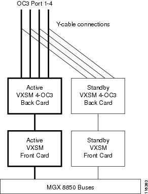
In this scheme, VXSM front and back card sets are installed in pairs: an active set and a standby set. For this feature to operate, the active and standby VXSM card sets must be in adjacent slots (slots 1 and 2, 3 and 4, 5 and 6, 9 and 10, 11 and 12, 13 and 14).
The VXSM 4-OC 3 back card provides a data path between the VXSM front card and the optical transceivers on back cards. It also provides the data path between the redundant front card and the optical transceivers on back card for front card redundancy. The VXSM back card also provides a data path between the adjacent front card and the optical transceivers on the back card for 1:1 legacy APS implementation.
The VXSM back card has an NVRAM on the board, which can be accessed through a local front card or through the redundant front card when redundant configuration is enabled or through the adjacent back card when 1:1 legacy APS is enabled.
The 1:1 front and back card redundancy scheme is shown in Figure 2-15.
Figure 2-15 1:1 Front and Back Card Redundancy
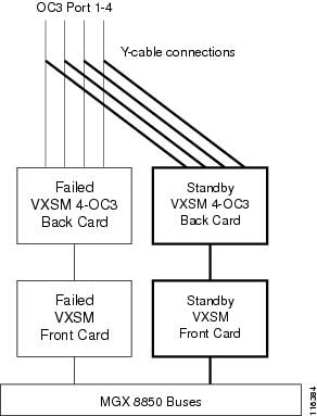
If a failure occurs in either the active front card or the active back card, the entire standby card set automatically switches over and becomes the active card set. The new data path after switchover is shown in Figure 2-16.
Figure 2-16 1:1 Front and Back Card Redundancy after Switchover
Line Redundancy
SONET line APS redundancy can be set up either as same card or adjacent card.
In same card redundancy, a second, 4 OC-3 back card is installed in the lower bay providing lines 5 to 8 in addition to the lines 1 to 4 in the upper bay. One line in the upper bay is designated the working line and one line in the lower bay is designated the protection line.
In adjacent card redundancy, a VXSM front and back card set are installed in adjacent slots. Line redundancy is provided by designating one line on one back card and one line on the other back card as the working/protection set.
1+1 APS Line Redundancy
VXSM cards with SONET back cards also support 1+1 APS line redundancy in which there are two channels:
•![]() Channel 1—Working channel
Channel 1—Working channel
•![]() Channel 2—Protection channel
Channel 2—Protection channel
In 1+1 APS architecture, the source node sends the data on both working and protection channel to the destination simultaneously. The destination chooses to receive the data from one of the two fiber channels, called the working channel.
If there is a failure in the working channel due to fiber cut or other reasons then the destination simply switches over to the protection channel. The destination continues to receive the data from the protection channel even after the other channel is fixed which is referred as nonrevertive mechanism.
1+1 APS line redundancy can operate on both same card and adjacent card redundant configurations.
1:1 APS Line Redundancy
VXSM cards with SONET back cards support 1:1 APS line redundancy
1:1 APS architecture is similar to 1+1 APS architecture in that there are also two fiber channels. Traffic is, however, transmitted only on the working channel. When the network is operating under normal conditions, the protection channel is unused or only used for carrying low priority traffic. The nodes switch the traffic to protection channel only when a failure occurs.
1:1 APS line redundancy can only operate on a same card redundant configuration.
48 T1/E1 and 6 T3 Systems
The 24 T1/E1 backcard and the 3 T3 backcard are designed to support:
•![]() 1:1 front card/back card redundancy
1:1 front card/back card redundancy
•![]() 1:1 front card redundancy
1:1 front card redundancy
1:1 Front Card/Back Card Redundancy
Two VXSM front cards are installed in adjacent slots. Each VXSM T1/E1 or VXSM T3 front card has two back cards installed, one in the upper bay and one in the lower bay.
For T1/E1 systems, each card has two 50-pin connectors, one for transmit and one for receive. Y-cables are used to connect lines to the corresponding connectors on each card set.
For T3 systems, each back card has two SMB connectors per port, one for transmit and one for receive, appropriate Y-cables can be used to connect lines to the corresponding connectors on each card set.
An example of a redundant arrangement for T1/E1 is shown in Figure 2-17.
Figure 2-17 1:1 Front Card/Back Card Redundancy
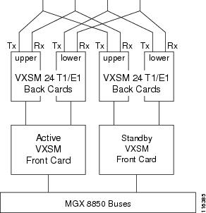
For this type of redundancy, one card set is the active set and the card set in the adjacent slot is the standby. During operation, both the card sets receive traffic, but only the active set transmits on the lines. If any failure occurs in the active front card, top back card, or bottom back card, the redundant card set becomes the active card set. The switchover is supported with the Y cables. Therefore, in the case of a switchover, complete traffic (on all 48 T1 or E1 lines) is transferred to the adjacent slot.
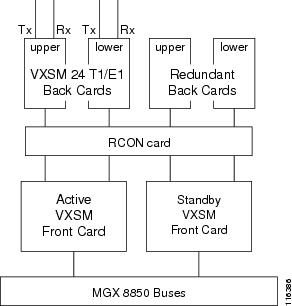
1:1 Front Card Redundancy
The 1:1 Front Card Redundancy scheme differs from the 1:1 Front Card Back Card scheme in that the redundant card set has redundant back cards (that do not have the lines connected to them) instead of 48 T1/E1 or 6 T3 back cards. In this scheme Y cable operation is not supported. A 1:1 front card redundancy is shown in Figure 2-18.
In this case, a RCON card (gang card) is needed and there is no back card redundancy. The redundant back card is required to switch traffic from the active front card to the redundant front card if a failure occurs. The 1:1 redundancy is achieved with the RCON (gang card used for 1:N redundancy but with N=1 only).
Figure 2-18 1:1 Front Card Redundancy
Processing Fax and Modem Traffic
VXSM supports the transmission of non-voice traffic such as clear channel, fax, and modem generated messages. VXSM can be configured such that, when a call is established, modem tones and fax preambles can be detected and acted upon accordingly. Nonvoice calls, when detected, can be handled by two methods, namely:
•![]() Fax/modem passthrough
Fax/modem passthrough
•![]() T.38 fax relay
T.38 fax relay
How the method is selected is user configurable. The user choices are:
•![]() Select fax/modem passthrough only
Select fax/modem passthrough only
•![]() Select T.38 fax relay only
Select T.38 fax relay only
•![]() Select T.38 first and, if that fails, select fax/modem passthrough
Select T.38 first and, if that fails, select fax/modem passthrough
Fax/Modem/TTY Passthrough
Within a voice circuit call, VXSM supports the handling of voiceband data (vbd) such as fax, modem, and TTY transmissions. Upon detection of a voiceband tone, VXSM will perform the necessary upspeed procedure that may involve any of the following processes:
•![]() Perform CAC calculations
Perform CAC calculations
•![]() Codec manipulation
Codec manipulation
•![]() Silence suppression
Silence suppression
•![]() Disabling echo cancellation
Disabling echo cancellation
•![]() Modify packetization period, gain, DC offset, and jitter parameters
Modify packetization period, gain, DC offset, and jitter parameters
Note ![]() Whether or not packetization period and VAD control are changed upon voiceband data detection can be controlled by the user. A voiceband data profile is maintained by VXSM that includes user configurable items that determine whether or not packetization period and VAD are enabled or disabled.
Whether or not packetization period and VAD control are changed upon voiceband data detection can be controlled by the user. A voiceband data profile is maintained by VXSM that includes user configurable items that determine whether or not packetization period and VAD are enabled or disabled.
If either packetization control or VAD control is set to 'enable', the VBD module changes the values to the user configured values in VBD profile. If the packetization control and VAD control are set to 'disable', the values are not changed during upspeed.
Likewise, whether or not echo cancellation and NLP (non-linear processing) are changed upon voiceband detection can also be controlled by the user. Two parameters in the VBD profile (-ecan<EcanOverride> and -npl<NPLOverride>) can be enabled or disabled by the user. If ECANControl is set to enable, ECAN and NLP are both disabled upon detecting the first VBD tones for both high speed and low speed modems irrespective of the value of NLPControl. If ECANControl is set to disable, ECAN is not changed and NLP is changed based on the NLPControl value. If NLPControl is set to enable, NLP processing is disabled and if it is set to disable, NLP is not changed.
For upspeed to operate correctly, both ends of the connection must perform the upspeed procedure. For this reason, VXSM informs the other (remote) end of the connection when an upspeed procedure is to be performed. For fax/modem/TTY upspeed, there are two different methods by which upspeed at the remote end is triggered:
1. ![]() Passthrough with NSE—VXSM informs the remote end when it detects a voiceband tone on the voice TDM side of a call. This procedure involves a Cisco proprietary protocol in which a Named Signaling Event (NSE) is sent to the remote end. This method can be used for connections where both ends are VXSM cards or where one end is a VXSM card and the other end is a NSE compliant Cisco product.
Passthrough with NSE—VXSM informs the remote end when it detects a voiceband tone on the voice TDM side of a call. This procedure involves a Cisco proprietary protocol in which a Named Signaling Event (NSE) is sent to the remote end. This method can be used for connections where both ends are VXSM cards or where one end is a VXSM card and the other end is a NSE compliant Cisco product.
2. ![]() Fax/modem passthrough with IP side tone detection—Relies on both ends of the connection being able to detect tones on both the TDM and IP sides. Thus both the originating and the terminating ends of the connection are able to detect the necessary tones and the need for any NSE type of message is eliminated. This method can be used with NSE compliant or none NSE compliant devices.For TTY upspeed, only the second method is supported.
Fax/modem passthrough with IP side tone detection—Relies on both ends of the connection being able to detect tones on both the TDM and IP sides. Thus both the originating and the terminating ends of the connection are able to detect the necessary tones and the need for any NSE type of message is eliminated. This method can be used with NSE compliant or none NSE compliant devices.For TTY upspeed, only the second method is supported.
Fax/modem/TTY passthrough features are as follows:
•![]() Fax/modem/TTY passthrough with IP side tone detection is supported with TGCP, MGCP, or H.248 call setup
Fax/modem/TTY passthrough with IP side tone detection is supported with TGCP, MGCP, or H.248 call setup
•![]() FAX/modem/TTY provisioning redundancy
FAX/modem/TTY provisioning redundancy
•![]() Upspeed from voice codec to upspeed codec G.711u, G.711a, G.726-32 or clear channel
Upspeed from voice codec to upspeed codec G.711u, G.711a, G.726-32 or clear channel
•![]() Graceful upgrade for fax/modem/TTY provisioning
Graceful upgrade for fax/modem/TTY provisioning
•![]() Detection of the following tones, TTY (1400 Hz), CNG (1100 Hz), CED/ANS (2100 Hz), CED/ANS (2100 Hz with phase reversal) and V.21 fax preamble
Detection of the following tones, TTY (1400 Hz), CNG (1100 Hz), CED/ANS (2100 Hz), CED/ANS (2100 Hz with phase reversal) and V.21 fax preamble
•![]() Detection of low speed modem tones, 2225 Hz (Bell modem), 2250 (USB1, V.22 bis), V.8bis, V.23-modem, and V.21-modem
Detection of low speed modem tones, 2225 Hz (Bell modem), 2250 (USB1, V.22 bis), V.8bis, V.23-modem, and V.21-modem
•![]() Bell low speed modem support for Bell 103/108/113, Bell 201, Bell 202,Bell 208, Bell 209, and Bell 212A
Bell low speed modem support for Bell 103/108/113, Bell 201, Bell 202,Bell 208, Bell 209, and Bell 212A
•![]() Revert back to voice mode for fax/modem upspeed after silence detected for the configured inactivity duration.
Revert back to voice mode for fax/modem upspeed after silence detected for the configured inactivity duration.
•![]() A TTY call does not revert back to voice mode as TTY devices may have genuine silence between character transmission
A TTY call does not revert back to voice mode as TTY devices may have genuine silence between character transmission
T.38 Fax Relay
The T.38 fax relay method supports fax transmissions from standard group 3 fax machines(G3FE) only. Initially, during call setup, both the MG and MGC do not know whether the call involves non-voice transmissions or not. However, once a call is setup and the tones and T.30 fax preamble indicate a group 3 fax transmission, the option of T.38 fax relay provides an alternative to the fax/modem passthrough method.
In general, fax relay offers smaller bandwidth demands on the packet network and provides greater security.
For gateway controlled T.38, switching to T.38 involves Modify or the use of Named Signaling Events (NSE) to handle the handshake between the originating and receiving gateways. Supported Named Signal Events are:
•![]() 192—Detecting 2100 Hz ANS tone
192—Detecting 2100 Hz ANS tone
•![]() 193—Detecting 2100 Hz phase reversal/ANS tone
193—Detecting 2100 Hz phase reversal/ANS tone
•![]() 200—Switch to T.38
200—Switch to T.38
•![]() 201—T.38 switch complete
201—T.38 switch complete
•![]() 202—T.38 switch fails.
202—T.38 switch fails.
In fax relay mode, the emitting gateway demodulates the T.30 transmission received from the calling terminal. The ITU-T.30 facsimile control and the image data are transferred as an octet stream structure using Internet Facsimile Protocol (IFP) packets, over the transport protocol (UDP) across the packet network.
The receiving gateway decodes the transferred information and establishes communication with the called facsimile terminal using normal T.30 procedures. The receiving gateway forwards all relevant responses from the called terminal to the emitting gateway.
For error protection, VXSM supports the "Use of Redundancy Messages" scheme as described in the ITU-T.38 recommendation, section 9.1.4.1.
Note ![]() The FEC scheme of error protection in ITU-T.38 is not supported.
The FEC scheme of error protection in ITU-T.38 is not supported.
The supported T30 INDICATOR types are:
•![]() No signal
No signal
•![]() V.21 Preamble Flags
V.21 Preamble Flags
•![]() V.27 2400 modulation training
V.27 2400 modulation training
•![]() V.27 4800 modulation training
V.27 4800 modulation training
•![]() V.29 7200 modulation training
V.29 7200 modulation training
•![]() V.29 9600 modulation training
V.29 9600 modulation training
•![]() V.17 7200 modulation short training
V.17 7200 modulation short training
•![]() V.17 7200 modulation long training
V.17 7200 modulation long training
•![]() V.17 9600 modulation short training
V.17 9600 modulation short training
•![]() V.17 9600 modulation long training
V.17 9600 modulation long training
•![]() V.17 12 000 modulation short training
V.17 12 000 modulation short training
•![]() V.17 12 000 modulation long training
V.17 12 000 modulation long training
•![]() V.17 14 400 modulation short training
V.17 14 400 modulation short training
•![]() V.17 14 400 modulation long training
V.17 14 400 modulation long training
The T.38 Fax Relay feature can be either Call Agent (CA) controlled or Gateway controlled. Both of which support MGCP, TGCP, and H.248 call control protocols.
However, the following four T.38 options are available with MGCP and TGCP call control only:
•![]() T.38 Strict—In this option the MGC has control of the T.38 operation. This option requires an indication during call setup that the terminating end can support T.38.
T.38 Strict—In this option the MGC has control of the T.38 operation. This option requires an indication during call setup that the terminating end can support T.38.
•![]() T.38 Loose—This option is the same as the T.38 Strict option except that no confirmation of T.38 support at the terminating end is required.
T.38 Loose—This option is the same as the T.38 Strict option except that no confirmation of T.38 support at the terminating end is required.
•![]() Off—In this option no special procedure is invoked for fax traffic.
Off—In this option no special procedure is invoked for fax traffic.
•![]() Gateway—In this option the MG handles the fax calls without further involvement of the MGC
Gateway—In this option the MG handles the fax calls without further involvement of the MGC
T.38 Fax Relay Statistics
VXSM accumulates two type of statistics fax calls:
•![]() The RTP statistics which occurs in the beginning of the call before switching to T.38 mode.
The RTP statistics which occurs in the beginning of the call before switching to T.38 mode.
•![]() Fax specific statistics collected during T.38 operation.
Fax specific statistics collected during T.38 operation.
Both the statistics types are maintained separately in the GWs.
The following fax relay statistics are available to users through the CLI. However, they are not be available through SNMP.
•![]() Total number of FAX packets sent to network
Total number of FAX packets sent to network
•![]() Number of FAX packets dropped due to the busy network
Number of FAX packets dropped due to the busy network
•![]() Total number of valid FAX packets received from the network
Total number of valid FAX packets received from the network
•![]() Number of lost network packets
Number of lost network packets
•![]() Number of invalid packets received from the network
Number of invalid packets received from the network
•![]() Count of out-of-sequence packets received from the network
Count of out-of-sequence packets received from the network
•![]() Most recent high-speed modulation
Most recent high-speed modulation
•![]() Number of complete pages transferred
Number of complete pages transferred
T.38 Fax-Relay Support for SG3 Fax Machines at G3 Speeds
The SG3 Fax Spoofing feature allows Super Group 3 (SG3) fax machines to interoperate over T.38 fax-relay network. The capability to interoperate over fax-relay networks is achieved by enabling SG3 fax machines to negotiate down to G3 speeds by suppressing the SG3 V.34 fax call menu (CM) signal. The suppression of the SG3 V.34 fax CM signal (or message) is also known as SG3 spoofing.
Note ![]() SG3-Spoofing is not supported on AAL2 trunking.
SG3-Spoofing is not supported on AAL2 trunking.
Information About Fax-Relay Support for SG3 Fax Machines at G3 Speeds
To configure SG3 spoofing feature on VXSM, you should understand the following concepts:
•![]() Fax CM Message Tone Suppression
Fax CM Message Tone Suppression
•![]() One-Gateway and Two-Gateway Solutions for Configuring SG3 Fax Machines at G3 Speeds
One-Gateway and Two-Gateway Solutions for Configuring SG3 Fax Machines at G3 Speeds
Fax CM Message Tone Suppression
Super Group 3 (SG3) is the standard for fax machines that support speeds of up to 33.6 kbps through V.34 half duplex (HD) modulation and V.34 signaling.
The use of SG3 V.34 fax CM message suppression provides a gateway-controlled solution that enables SG3 fax machines to scale down without end-user interaction and without the extra bandwidth requirement.
SG3 V.34 fax CM message suppression allows SG3 fax machines to interoperate over a fax-relay network at G3 speeds by blocking the SG3 V.34 CM message, from reaching the called fax machine.
One-Gateway and Two-Gateway Solutions for Configuring SG3 Fax Machines at G3 Speeds
The fax relay support for SG3 fax machines at G3 speeds feature supports both the one-gateway and two-gateway solutions:
•![]() With a one-gateway solution, the gateway on one end of the call can be configured to suppress the SG3 V.34 fax CM message independent of the gateway on the other end of the call. The one-gateway solution suppresses the fax CM tone on either TDM or IP interface, and can interoperate with third-party gateways where fax CM tone suppression feature is not supported.
With a one-gateway solution, the gateway on one end of the call can be configured to suppress the SG3 V.34 fax CM message independent of the gateway on the other end of the call. The one-gateway solution suppresses the fax CM tone on either TDM or IP interface, and can interoperate with third-party gateways where fax CM tone suppression feature is not supported.
•![]() With a two-gateway solution, this feature is enabled on both the ends of the gateways. The two-gateway solution suppresses the fax CM tone on the time-division multiplexing (TDM) interface of the originating gateway and does not allow the other gateway to process CM message. When an SG3 device is connected to the terminating gateway, it is negotiated down to G3 speeds.
With a two-gateway solution, this feature is enabled on both the ends of the gateways. The two-gateway solution suppresses the fax CM tone on the time-division multiplexing (TDM) interface of the originating gateway and does not allow the other gateway to process CM message. When an SG3 device is connected to the terminating gateway, it is negotiated down to G3 speeds.
Note ![]() If both the originating gateway and the terminating gateways are configured for V.34 fax CM message suppression, then the suppression occurs on the originating gateway.
If both the originating gateway and the terminating gateways are configured for V.34 fax CM message suppression, then the suppression occurs on the originating gateway.
Network Bypass Feature
Network Bypass is a feature of a VXSM based media gateway for the efficient handling of calls that originate and terminate on the same gateway. This feature operates with H.248 media gateway control protocol only.
Depending upon the destination, incoming calls on a VXSM card can be routed in the following ways.
The call is for a DS0:
•![]() On another gateway and is routed over the IP network to that gateway.
On another gateway and is routed over the IP network to that gateway.
•![]() On another VXSM card but in the same gateway.
On another VXSM card but in the same gateway.
•![]() On the same VXSM card.
On the same VXSM card.
The VXSM network bypass feature, when enabled, examines the destination (NSAP address prefix) of each incoming call and makes a determination as to which of the three routing situations applies. If the incoming call is for a ds0 on the same or another VXSM card in the same gateway, the routing of the bearer circuit is made entirely within the VXSM cards in the gateway and does not involve the IP network. In this way the unnecessary use of network resources is eliminated.
Network bypass employs a mesh of user configured internal PVCs. The mesh consists of the following connections.
•![]() Each VXSM card has PVC connections to all the other VXSM cards in the gateway. These connections provide direct inter-VXSM routing.
Each VXSM card has PVC connections to all the other VXSM cards in the gateway. These connections provide direct inter-VXSM routing.
•![]() Each VXSM card has a PVC connection that is looped back to itself. The looped connection provides direct intra-VXSM routing.
Each VXSM card has a PVC connection that is looped back to itself. The looped connection provides direct intra-VXSM routing.
•![]() Each VXSM card should have at least one external PVC (between VXSM and RPM or AXSM card) that is used to send the bearer traffic to an IP network.
Each VXSM card should have at least one external PVC (between VXSM and RPM or AXSM card) that is used to send the bearer traffic to an IP network.
Figure 2-19 shows an example of the PVCs for a three VXSM gateways.
Figure 2-19 PVC Mesh for Network Bypass—Example
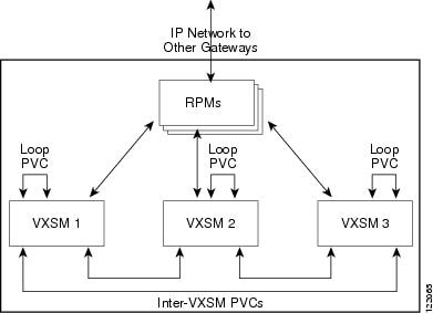
Jitter Compensation
An inherent characteristic of packet networks is that the inter-arrival times of voice frames are subject to a certain amount of variation (inter-arrival jitter). The VXSM card uses a buffering mechanism to eliminate, or minimize, the amount of jitter passed from the packet network to the conventional telephone (TDM) network.
Voice frames received from the packet network are placed in a playout buffer where they experience a defined delay before being transmitted to the TDM network. In this way voice frames are transmitted in a more regular (synchronous) manner.
The amount of delay, in milliseconds, introduced by the buffer is determined by the values of three user configurable parameters known as nominal jitter delay, maximum jitter delay, and minimum jitter delay, respectively.
Nominal jitter delay is normally used to determine the delay and its value should be that of the expected average jitter experienced on the packet network (depends upon the network design, queuing delays, VAD on or off, codec frame size, and packetization period). Further, the value of the nominal jitter delay used by the buffer depends upon the buffer playout mode which can be either fixed or adaptive.
•![]() Fixed mode—The value is a fixed delay explicitly configured by the user. Fixed mode is normally used for voice band data, fax, modem, and clear channel.
Fixed mode—The value is a fixed delay explicitly configured by the user. Fixed mode is normally used for voice band data, fax, modem, and clear channel.
•![]() Adaptive mode—The initial value is specified by the user but the actual value is derived from the jitter characteristics of the packet network. Adaptive mode is generally used for voice codecs.
Adaptive mode—The initial value is specified by the user but the actual value is derived from the jitter characteristics of the packet network. Adaptive mode is generally used for voice codecs.
The value used for the delay cannot be outside the range specified by user-configured minimum and maximum jitter delay values.
Alarms and Statistics
VXSM can monitor a large number of operational parameters and measure their values against configurable threshold values. When a parameter falls outside its valid threshold, an alarm is set. Likewise, VXSM maintains a large number of counters for the purpose of collecting and maintaining running statistics.
LED Indicator Alarms
The first level of alarm/status indicators are the LEDs located on the faceplate of the VXSM front card. Some of these LEDs refer to card level alarms and others to port level alarms.
Card Level LEDs
There are three card-level LEDs:
•![]() Active LED (green)—Card is in the Active state.
Active LED (green)—Card is in the Active state.
•![]() Standby LED (orange)—Card is in the Standby state, or the card's DSPs are being downloaded as part of card boot-up. Standby LED blinks orange when the card is in the boot state.
Standby LED (orange)—Card is in the Standby state, or the card's DSPs are being downloaded as part of card boot-up. Standby LED blinks orange when the card is in the boot state.
•![]() Fail LED (red)—Card is in the Fail state.
Fail LED (red)—Card is in the Fail state.
Port Level LEDs
Port-level LEDs exist for each port supported by the front card: 4 LEDs for the OC-3 version, and 48 for the T1/E1 version.
The line LEDs are lit:
•![]() Green—If the line is added and there is no alarm on the line.
Green—If the line is added and there is no alarm on the line.
•![]() Orange—If the line is added and there is a Yellow alarm condition on the line.
Orange—If the line is added and there is a Yellow alarm condition on the line.
•![]() Red—If the line is added and a LoS condition exists (Red alarm condition) on the line.
Red—If the line is added and a LoS condition exists (Red alarm condition) on the line.
Software Alarms
VXSM software is equipped to display a large number of alarm conditions through display commands. An equivalent set of configure commands permit the user to set threshold levels that, when exceeded, trigger individual alarms.
For example, alarms supported for OC-3 ports include.
•![]() sonet line
sonet line
•![]() sonet section
sonet section
•![]() sonetpath ds1, ds3, E1, sts
sonetpath ds1, ds3, E1, sts
Statistics
Statistics related to the network interfaces and ATM connections can be collected and stored locally on the card as statistics files. Users can see the value of the collected statistics either by executing certain display commands (for example, dspsvccnt to display SVC counters) or uploading the statistics files to a network management system such as Cisco WAN Manager.
The cnfcdstat (configure card statistics) command can be used to:
•![]() Enable/disable statistics collection
Enable/disable statistics collection
•![]() Configure the bucket interval (within the collection interval)
Configure the bucket interval (within the collection interval)
•![]() Configure the collection interval
Configure the collection interval
•![]() Configure the level of statistics to be collected
Configure the level of statistics to be collected
Data for previous intervals can be uploaded to an NMS while a current interval of data is being collected. When the data for the current interval is collected, another statistics file is created with a filename based on the current timestamp. Statistics files for up to ten intervals can be maintained locally on the card. Older intervals are automatically purged, whether or not they have been uploaded
Some example commands for displaying statistics are:
•![]() dspbert—display BERT counters
dspbert—display BERT counters
•![]() dspchancnt—display channel counters
dspchancnt—display channel counters
 Feedback