- About This Guide
- Cisco Voice Switch Service Module Introduction
- Cisco Voice Switch Service Module Description
- Configuring VoIP Switching Applications
- Configuring Switches for AAL2 Trunking Applications
- Configuring VXSM Features
- VXSM as a Signaling Gateway
- VXSM as a Transcoding Gateway
- Implementing Lawful Intercept on VXSM
- Configuring Lawful Intercept Support
- Loading and Upgrading VXSM Code Images
- VXSM Troubleshooting
- Media Gateway Clocking
VXSM as a Signaling Gateway
Signaling Gateway Description
A VXSM card in an MGX 8880 and functioning as a media gateway can also be configured to provide the functions of a signaling gateway between SS7 and IP networks. By this means, communication can be established between entities, such as Signaling End Points, on a SS7 network and Application Servers, such as a Media Gateway Controller, on an IP network.
VXSM supports one instance of a Signaling Gateway that can operate concurrently with one or several instances of Media Gateways.
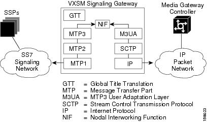
The VXSM signaling gateway feature permits up to 16 DS0 lines on a VXSM card to be configured as SS7 signaling lines. As shown in Figure 6-1, signaling messages to and from the SS7 network use the MTP1, MTP2, and MTP3 layers of the SS7 protocol stack. Received messages have the MTP3 component extracted and relayed onto the IP network using the M3UA, SCTP, and IP protocol stack. The interworking at the MTP3 level is performed by a Nodal Interworking Function (NIF).
At the MTP2 level messages destined to the local point code are queued for local processing. An example of this are messages that require their dialed digits to be translated to an address format that can be used by MTP to route the message. Such translation is performed by the Global Title Translation (GTT) module. Messages not requiring local processing are passed to NIF for further routing.
Figure 6-1 VXSM Signaling Gateway Protocol Stacks
A summary list of the VXSM Signaling Gateway Features is as follows:
•![]() Up to 16 SS7 Low Speed Signalling Links (64Kpbs)
Up to 16 SS7 Low Speed Signalling Links (64Kpbs)
•![]() 1:1 hot card redundancy for both configuration and dynamic data
1:1 hot card redundancy for both configuration and dynamic data
•![]() Command Line Interface (CLI) for VXSM SG/MG configuration
Command Line Interface (CLI) for VXSM SG/MG configuration
•![]() SNMP Management interface through MIBs to configure SG/MG and to display and retrieve status and statistics
SNMP Management interface through MIBs to configure SG/MG and to display and retrieve status and statistics
•![]() Concurrent SG operation of M3UA, IUA, and DUA
Concurrent SG operation of M3UA, IUA, and DUA
•![]() Support both ITU and ANSI SS7 variants
Support both ITU and ANSI SS7 variants
•![]() SCTP for M3UA Transport layer; SCTP compliant with RFC 2992
SCTP for M3UA Transport layer; SCTP compliant with RFC 2992
•![]() M3UA implementation compliant with RFC 3332. Refer [9] for compliance details
M3UA implementation compliant with RFC 3332. Refer [9] for compliance details
•![]() SCCP support for Global Title Translation
SCCP support for Global Title Translation
•![]() Multiple Point Code Assignment
Multiple Point Code Assignment
•![]() AS point code assignment and management
AS point code assignment and management
•![]() Flexible AS routing key assignment
Flexible AS routing key assignment
•![]() AS traffic mode: load-sharing, over-ride and broadcast
AS traffic mode: load-sharing, over-ride and broadcast
•![]() ASP to ASP routing through the SG by using routing keys
ASP to ASP routing through the SG by using routing keys
•![]() QOS mapping to IP TOS for M3UA traffic.
QOS mapping to IP TOS for M3UA traffic.
Signaling Gateway Statistics
The VXSM Signaling Gateway supports the collection of statistics on both the SS7 and IP networks. The values of the statistics counters can be uploaded to a Network Management System upon demand.
On the SS7 side, up to 64 entries of link statistics counters can be collected periodically and upload to NMS on demand. On the IP side, a maximum of 16 entries of ASP statistics can be collected and uploaded.
SS7 Statistics Supported
The number of MTP3 packets received by this link Q752/3.5
The number of MTP3 packets sent by this link Q752/3.3
The number of MTP3 bytes received by this link Q752/3.4
The number of MTP3 bytes send by this link Q752/3.1
The number of MTP3 packets retransmitted on this link Q752/3.2
The number of MTP3 bytes retransmitted on this link Q752/3.2
Duration of link in the In-Service state Q752/1.1
Count of Signaling Link failure—All reasons Q752/1.2.
Count of Signaling Link failure—Abnormal FIBR/BSNR Q752/1.4
Count of Signaling Link failure—Excessive delay of acknowledgement Q752/1.4
Count of Signaling Link failure—Excessive error rate Q752/1.5
Count of Signaling Link failure—Excessive duration of congestion Q752/1.6
Count of alignment or proving errors Q752/1.7
Count of signal units received in error Q752/1.8
Count of negative acknowledgement received Q752/1.9
Count of local automatic changeover events Q752/1.10
Count of local automatic changeback events Q752/1.11
Duration of Signaling Link unavailable (for any reason) Q752/2.1
Duration of Signaling Link unavailable due to local management actions Q752/2.5
Duration of Signaling Link unavailable due to remote management actions Q752/2.6
Duration of Signaling link unavailable due to link failure Q752/2.7
Duration of Signaling Link unavailable due to remote processor outage Q752/2.9
Count of remote processor outage events Q752/2.10 and Q752/2.11
Duration of local busy Q752/2.15
Count of local inhibition Q752/2.16 and Q752/2.17
Count of remote inhibition Q752/2.18 and Q752/2.19
The number times this signaling link was marked congested. This measurement is specified in Q752/3.6
Cumulative duration of signaling link congestion Q752/3.7
The number of packets (MSUs) discarded due to signaling link level 1 congestion Q752/3.10
The number of packets (MSUs) discard due to signaling link level 2 congestion Q752/3.10
The number of packets (MSUs) discard due to signaling link level 3 congestion Q752/3.10
The number times this signaling link entered congestion level 1 and packets were discarded. Q752/3.11
The number times this signaling link entered congestion level 2 and packets were discarded. Q752/3.11
The number times this signaling link entered congestion level 3 and packets were discarded. Q752/3.11
IP Statistics Supported
The number of data packets received from this ASP
The number of data packets sent to this ASP
The number of data packets received from MTP3
The number of data packets sent to MTP3
The number of ASP Up messages received
The number of ASP Up ACK messages sent
The number of ASP Up ACK messages sent
The number of ASP Down ACK messages sent
The number of ASP Active messages received
The number of ASP Active ACK messages sent
The number of ASP Inactive messages received
The number of ASP Inactive ACK messages sent
The number of ASP Error messages received
The number of ASP Error messages sent
The number of ASP Notify messages sent
The number of Destination Unavailable messages received
The number of Destination Unavailable messages sent
The number of Destination Available messages received
The number of Destination Available messages sent
The number of Destination User Part Unavailable messages received
The number of Destination User Part Unavailable messages sent
The number of Destination State Audit messages received
The number of Destination State Audit messages sent
The number of Signaling Congestion messages with congestion level 0 (or no congestion) received
The number of Signaling Congestion messages with Congestion level 1 received
The number of Signaling Congestion messages with Congestion level 2 received
The number of Signaling Congestion messages with Congestion level 3 received
The number of Signaling Congestion messages with Congestion level 0 sent
The number of Signaling Congestion messages with Congestion level 1 sent
The number of Signaling Congestion messages with Congestion level 2 sent
The number of Signaling Congestion messages with Congestion level 3 sent
Configuring a Signaling Gateway
Setting up a Signaling Gateway on a VXSM card consists of configuring the following items.
•![]() The SS7 network side of the signaling gateway.
The SS7 network side of the signaling gateway.
•![]() The IP network side of the signaling gateway
The IP network side of the signaling gateway
•![]() The Application Severs and Application Server Processes
The Application Severs and Application Server Processes
•![]() The SCCP/GTT functions.
The SCCP/GTT functions.
Configure the SS7 Network Side
To configure the SS7 side of the Signaling Gateway, perform the following steps.
Step 1 ![]() Use the addss7 command to create an instance of the SS7 side of the signaling gateway. The format of this command is:
Use the addss7 command to create an instance of the SS7 side of the signaling gateway. The format of this command is:
addss7 <Ss7Variant> [-name <Name>][-nwind <NetworkIndicator>]
[-nwname <NetworkName>] [-tfr <TxRestrictedMsg>][-frestart <FastRestart>]
[-distsccp <DistributedSccp>][-multicong <MultiCongestion>]
[-sumroute <SummaryRouting>][-linktest <AutoLinkTest>][-prevtxp <PreventiveTxp>]
For Ss7Variant, set the variant as either 1 = ansi or 1 = itu.
For -name<Name>, if used, enter a Signaling Point identifier as a character string up to 30 characters.If this parameter is not specified, it defaults to the local point code
For -nwind <NetworkIndicator> enter a network indicator:
0 = international
1 = international Spare
2 = national
3 = natSpare
For -nwname <NetworkName> enter a network name, a character string up to 19 characters.
For -tfr <TxRestrictedMsg> enter whether Transfer Restricted messages are allowed or not.
1 = enable (allowed)
2 = disable (not allowed) (default)
For -frestart <FastRestart> enter the Fast Restart state
1 = enable
2 = disable (default)
For -distsccp <DistributedSccp> enter the Evenly Distributed Class 0 SCCP state
1= enable (allowed)
2 = disable (not allowed) (default)
For -multicong <MultiCongestion> enter Allow Multiple Congestion Levels
1= enable (allowed)
2 = disable (not allowed) (default)
For -sumroute <SummaryRouting> enter summary route state.
This parameter is used to control the usage of the summary route when both a summary route (or ANSI cluster route) and a full point-code route (within that summary) are configured. It is used to indicate whether the summary route is to be used when the full point-code destination is inaccessible as follows.
1= enable (allowed) (default)
2 = disable (not allowed)
For -linktest <AutoLinkTest> enter whether Auto Link Test is to be performed when link is up
1= enable (allowed)
2 = disable (not allowed) (default)
For -prevtxp <PreventiveTxp> enter whether a link test is automatically run when the link comes into service. Link test is performed by sending an SLTM message and verifying the acknowledgment (SLTA) from the adjacent node. A link test is automatically run when the link comes into service.
1= enable (allowed)
2 = disable (not allowed) (default = 2)
Step 2 ![]() To create an SS7 point code for the signaling gateway, use the addss7pc command. This command has the following format.
To create an SS7 point code for the signaling gateway, use the addss7pc command. This command has the following format.
addss7pc <PointCodeIndex> <PointCode><PointCodeType>
For <PointCodeIndex> enter a point code index, an integer in the range of 1 to 3.
For <PointCode> enter a point code in the format of <p1>.<p2>.<p3>,
where p1, p2, p3 = 0º255, for example 255.255.255
For <PointCodeType> enter the point code type.
1 - primary
2 - secondary
3 - capability
Step 3 ![]() To create an SS7 link set, use the addss7linkset command. The signaling gateway can have up to 64 linksets and a linkset can consist of up to 16 SS7 links.
To create an SS7 link set, use the addss7linkset command. The signaling gateway can have up to 64 linksets and a linkset can consist of up to 16 SS7 links.
addss7linkset <LinksetId> <SourcePointCodeId> <AdjPointCode>
[-name <LinksetName>][-slsrot <SlsRotate>][-slsshift <SlsShift>]
[-llinh <LastLinkInhibit>][-prof <ProfileId>][-shut <LocalInhibit>]
For <LinksetId> enter a Link Set ID, an index number in the range of 1 to 32.
For <SourcePointCodeId> enter the Source point code ID, an integer in the range of 1 to 3.
For <AdjPointCode> enter the adjacent point code in the format of <p1>.<p2>.<p3>,
where p1, p2, p3 = 0º255, for example 255.255.255
For -name <LinksetName> enter the name of the linkset, a character string of up 19 characters.
For -slsrot <SlsRotate> enter the signaling link selector rotation state. This defines whether or not signaling link selector (SLS) is rotated. This option only applies to ANSI variant and returns false for all other variants. By default, SLS rotation is enable by default for ANSI linksets. ANSI specifications state that SLS rotation should not be performed on C type linksets.
1 = enable (default)
2 = disable
For -slsshift <SlsShift> enter a value used to shift the signaling link selector (SLS) when rotation is enabled. This option only applies to ANSI variant and will return 0 all other variants. An integer in the range of 0 to 3.
For -llinh <LastLinkInhibit> enter whether taking out of service of the last link of a linkset is prohibited.
1 = Signaling gateway will first verify whether a link is the last link in the linkset when user tries to delete a link. If so, such action will be denied. (Default is 1).
2 = No checking is done, user could delete the last link from the linkset. In this case, one could loose the connectivity.
For -prof <ProfileId> Enter a profile ID, and integer in the range of 0 to 10. When specified this value indicates which profile will be used to establish defaults for common configuration values like MTP2 and MTP3 timers. The zero value is used to indicate that the linkset does not have a profile.
For -shut <LocalInhibit> enter the Linkset shutdown state
1 = shutdown
2 = not- shutdown
Repeat this command as necessary for each linkset to be configured.
Step 4 ![]() To create an SS7 link, use the addss7link command. A linkset can have up to 16 links. The format of this command is.
To create an SS7 link, use the addss7link command. A linkset can have up to 16 links. The format of this command is.
addss7link <LinksetId> <SignalLinkCode> <Ds0IfIndex>
[-name <LinkName>][-shut <LinkShut>][-test <SignalLinkTest>]
For <LinksetId> enter a linkset ID, an integer in the range of 1 to 32.
For <SignalLinkCode> enter a Signal Link Code, an integer in the range of 0 to 15.
For <Ds0IfIndex>, enter the line number of the link endpoint in one of the following formats.
OC3/SDH bay.line.path.vtg.vt:ds0 bay {1 - upper}
or bay.line.path.ds1:ds0 line (range=1º4)
path (range=1º3)
vtg (range=1º7)
vt (range=1º4)(ds1)
(range=1º3)(e1)
ds1 (range=1º28)
ds0 (range= 1º24 for T1
1º31 for E1)
T1/E1 bay.line:ds0 bay {1 - upper}
line (range=1º24)
ds0 (range= 1º24 for T1
1º31 for E1
T3 bay.line.ds1:ds0 bay {1 - upper}
line (range=1º3)
ds1 (range=1º28)
ds0 (range= 1º24 for T1
1º31 for E1
For -name <LinkName> enter the name of the link, a character string of up 20 characters.
For -shut <LinkShut> enter the Linkset shutdown state
1 = shutdown
2 = not- shutdown
For -test <SignalLinkTest>enter the Signaling Link Test state
1 = enable (default)
2 = disable
Repeat this command as necessary for each link to be configured.
Step 5 ![]() To create an SS7 Route, use the addss7route command. The signaling gateway can maintain characteristics of each SS7 route (for example, state of congestion) to determine how to handle messages to the SS7 network. The format of this command is.
To create an SS7 Route, use the addss7route command. The signaling gateway can maintain characteristics of each SS7 route (for example, state of congestion) to determine how to handle messages to the SS7 network. The format of this command is.
addss7route <Dpc> <DpcMask> <LinksetCost> <LinksetId>
For <Dpc> enter the destination point code of the route in the format of <p1>.<p2>.<p3>,
where p1, p2, p3 = 0º255, for example 255.255.255
Valid values are based on the SS7 variant (dspss7)
itu—7.255.7 or 7.255.0 or 7.0.0
ansi—255.255.255 or 255.255.0 or 255.0.0
For <DpcMask> enter the mask used to define which part of Destination Point Code is significant when comparing the Destination Point Code to the destination code point in the packet to be routed.Destination Point Code Mask
For <LinksetCost> enter the cost assigned to this linkset matching this route. Higher numbers represent higher cost. An integer in the range of 1 to 9.
For <LinksetId> enter the linkset ID. An index number in the range of 1 to 32.
Repeat this command as necessary for each route to be configured.
To add an SS7 Profile Timer, use the addss7proftimer command. The format of this command is:
addss7proftimer <ProfileIndex> <TimerNum> <TimerValue>
For <ProfileIndex> Enter an index number in the range of 1 to 32.
For <TimerNum> enter an Index into table containing timer information as follows;
1 = T01 16 = T116 31 = T31
2 = T02 17 = T117 32 = T32
3 = T03 18 = T118 33 = T33
4 = T04 19 = T119 34 = T34
5 = T05 20= T120 35 = T35
6 = T06 21 = T121 38 = alignReady
7 = T07 22 = T122 39 = notAlign
8 = T08 23 = T123 40 = align
9 = T09 24 = T124 41 = provNormal
10 = T010 25 = T125 42 = ProvEmerg
11 = T011 26 = T126 43 = sendSIB
12 = T012 27 = T127 44 = rmtCongest
13 = T013 28 = T128 45 = xDelayACK
14 = T014 29 = T129
15 = T015 30 = T130
For <TimerValue> enter a timer value in milliseconds.
Configure the IP Network Side
To configure the IP side of the Signaling Gateway, perform the following steps.
Step 1 ![]() Create an instance of the IP side of the signaling gateway, use the addl3ua command. The format of this command is.
Create an instance of the IP side of the signaling gateway, use the addl3ua command. The format of this command is.
addl3ua <SctpPort> [-shut <GwShut>][-rwin <RcvWindow>][-prio <UnorderPriority>] [-instrm <MaxInStream>][-queue <TxQDepth>][-assorx <MaxAssocRx>]
[-prx <MaxPathRx>][-csto <CumSackTo>][-bdl <BundleEnable>]
[-bdlto <BundleTo>][-initrx <MaxInitRx>][-maxir <MaxInitRto>]
[-minrto <MinRto>][-maxrto <MaxRto>][-kpalive <KeepAliveTo>]
For <SctpPort>This parameter specifies the local XUA SCTP port.
An integer in the range of 1 to 65535). The value zero is not allowed.
For -shut <GwShut> enter whether the signaling gateway (SG) XUA instance is shutdown or not.
1 = true (default). Indicates that the XUA Instance has been shutdown.
2 = false. Indicates that the XUA Instance is not shutdown
To configure this parameter to 'false' (to bring the XUA SG instance in service), at least one local IP has to be configured. Otherwise, the configuration attempt is rejected.
For -rwin <RcvWindow> enter the size of the advertised receiving window, in bytes, for the SCTP association. An integer in the range of 1500 to 65535 bytes)(default=64000)
For -prio <UnorderPriority> enter the delivery priority of the unordered data. 'high': delivered first before sequenced data 'equal': same priority as sequenced data.
1 = high
2 = equal (default)
For -instrm <MaxInStream> enter the maximum number of inbound SCTP streams allowed at this signaling gateway. An integer in the range of 1 to 336)(default=17)}
For -queue <TxQDepth> enter the allowed maximum number of ULP (Upper Layer Protocol) datagrams waiting to be sent in transmission queue. An integer in the range of 0 to 65535 datagrams)(default=1000)}
For -assorx <MaxAssocRx> enter the maximum number of data retransmissions in the association context. This value must be smaller than the maximum number of data retransmissions in the association context. An integer in the range of 2 to 10)(default=10)}
For -prx <MaxPathRx> enter the maximum number of data retransmission in a SCTP path for a remote IP. The remote IP is considered Inactive after retransmitting for the value specified in this parameter. An integer in the range of 2 to 10)(default=4)}
For -csto <CumSackTo> enter the amount of time to wait for the cumulative selective ACK. An integer in the range of 100. to 500 ms)(default=200)}
For -bdl <BundleEnable> enter whether to enable or disable SCTP user message bundling. Multiple user messages can be bundled into a single SCTP packet to transmit. During a period of congestion, the implementation bundles messages whenever possible even if bundling is disabled.
1 - true (default)
2 - false
For -bdlto <BundleTo> enter the maximum amount of time that SCTP will wait for messages for bundling. Multiple user messages can be bundled into a single SCTP packet. This parameter allows a user to configure the packet bundling interval to be used for a new SCTP association. An integer in the range of 100 to 1000 ms)(default=100)
For -initrx <MaxInitRx> Enter the maximum number of times SCTP initialization and cookie chunks to be retransmitted before reporting failure for association request. Modification of this parameter does not affect existing association as this parameter is used during association initialization. If this parameter is changed after association initialization, the new value will be used when restarting association. An integer in the range of range of 1 to 10)(default=8)
For -maxir <MaxInitRto> enter the retransmission interval for initialization and cookie chunks. Modification of this parameter does not affect existing association as this parameter is used during association initialization. If this parameter is changed after association initialization, the new value will be used when restarting association. An integer in the range of range of 2000 to 20000 ms)(default=1)
For -minrto <MinRto> enter the lower bound for retransmission time out doubling operation, up on RTO timer expire. RFC 2960 specifies up on RTO timer expire, retransmission time out values should be doubled for the next retry. An integer in the range of range of 300 to 60000 ms)(default=1000)
For -maxrto <MaxRto> enter the upper bound for retransmission time out doubling operation, up on RTO timer expire RFC 2960 specifies up on RTO timer expire, retransmission time out values should be doubled for the next retry. User can specify upper bound for this retransmission time out. Once this value is reached, time out value is not going to be doubled. An integer in the range of range of range=300 to 60000 ms)(default=1000)
For -kpalive <KeepAliveTo> enter the heartbeat timeout interval for the SCTP path. An integer in the range of range of 500 to 60000 ms)(default=3000)
Step 2 ![]() To add an XUA local IP address for the signaling gateway IP side, use the addl3ualocip command. The format of this command is.
To add an XUA local IP address for the signaling gateway IP side, use the addl3ualocip command. The format of this command is.
addl3ualocip <LocIpIndex> <LocIpAddress>
For <LocIpIndex> enter a local IP index. An integer in the range of 1 to 4
For <LocIpAddress> enter the local IP address of the XUA signaling gateway in dotted decimal notation.
Step 3 ![]() Bring the gateway IP side to the up state, use the cnfl3ua command. To do this, the user need only specify the -shut parameter as follows.
Bring the gateway IP side to the up state, use the cnfl3ua command. To do this, the user need only specify the -shut parameter as follows.
cnfl3ua -shut 2
Configure the Application Server Processes and Application Servers
To configure the Application Server Processes and Application Servers, perform the following steps.
Step 1 ![]() To create an IP side (M3UA) Application Server Process, use the addl3uaasp command. The format of this command is.
To create an IP side (M3UA) Application Server Process, use the addl3uaasp command. The format of this command is.
addl3uaasp <AspIndex> <AspName> <RemotePort> [-aspshut <AspShut>]
[-aspblock <Block>][-aspqos <QosClass>] [-aspqueue <TxQDepth>]
[-aspassorx <MaxAssocRx>][-aspprx <MaxPathRx>] [-aspcsto <CumSackTo>]
[-aspbdl <BundleEnable>][-aspbdlto <BundleTo>] [-aspminrto <MinRto>]
[-aspmaxrto <MaxRto>][-aspka <KeepAliveTo>] [-mtype <MatchType>]
[-mqos <MatchQos>][-msi <MatchSi>]
For <AspIndex> enter an L3UA Application Server Process index. An integer in the range of 1 to 16.
For <AspName> enter the name of the Application Server Process. A character string of up to 12 characters.
For <RemotePort> enter the configured remote SCTP port number used to create the association. The value zero means any nonzero remote port is acceptable. An integer in the range of 0 to 65536.
For -aspshut <AspShut> enter the ASP state.
1 = true (default). Indicates that the ASP has been shutdown
2 = false. Indicates that the ASP is not shutdown.
To configure this parameter to false, at least one ASP remote IP must have been added. Otherwise, the attempt is rejected.
For -aspblock <Block> enter whether ASP is blocked or not.
When an ASP is blocked, it cannot receive normal data traffic, but it can send or receive control messages.
1 = true. Indicates that the ASP has been blocked by an administrative action.
2 = false (default). Indicates that the ASP is not blocked.
When this parameter is set to false, all of the configured remote IP take effect, and this ASP is ready for service. The SCTP association are created and all the configuration for this ASP are in sync with the SCTP layer. After true is configured when the previous value is false, service is interrupted.
For -aspqos <QosClass> enter the QOS class for the ASP. An integer in the range of 0 to 7 (default = 0). A value of zero (0) indicates that QOS class is not defined.
When QOS class is defined, it overrides the QOSclass specified in the addqosclass and cnfqosclass commands.
For -aspqueue <TxQDepth> enter the allowed maximum number of ULP (Upper Layer Protocol) datagrams waiting to be sent in transmission queue. An integer in the range of 0 to 65535 datagrams) (default=1000).
For -aspassorx <MaxAssocRx> enter the cumulative selective acknowledgment time-out value used when a new SCTP association starts.An integer in the range of 100 to 500 (default=200).
For-aspprx <MaxPathRx> enter the maximum number of data retransmission in a SCTP path for a remote IP. The remote IP is considered Inactive after retransmitting for the value specified in this parameter. An integer in the range of 2 to 10) (default=4).
For -aspcsto <CumSackTo> enter the cumulative selective acknowledgment time-out value used when a new SCTP association starts.An integer in the range of 100 to 500 (default=200).
For -aspbdl <BundleEnable> enter whether to enable or disable SCTP user message bundling.
1 = true
2 = false (default=1)
Multiple user messages can be bundled into a single SCTP packet to transmit. During period of congestion, the implementation bundles messages whenever possible even if bundling is disabled.
For -aspbdlto <BundleTo> enter the maximum amount of time that SCTP will wait for messages bundling. An integer in the range of 100 to 1000 ms) (default=100)
For -aspminrto <MinRto> enter the lower bound for retransmission time out doubling operation, up on RTO timer expire RFC 2960 specifies up on RTO timer expire, retransmission time out values should be doubled for the next retry. An integer in the range of 300 to 60000 ms) (default=100).
For -aspmaxrto <MaxRto> enter the upper bound for retransmission time out doubling operation, up on RTO timer expire RFC 2960 specifies up on RTO timer expire, retransmission time out values should be doubled for the next retry. User can specify upper bound for this retransmission time out. Once this value is reached, time out value is not going to be doubled. An integer in the range of 300 to 60000 ms) (default=100).
For -aspka <KeepAliveTo> enter the heart beat timeout interval for the path. An integer in the range of 500 to 60000 ms) (default=3000).
For -mtype <MatchType> enter the match criterion to classifying packets for QoS functionality.
1 = matchNone (default)
2 = matchAny
3 = matchSi
For -mqos <MatchQos> enter the QoS class identifier used to assign a QoS class number to all inboundpackets.This parameter is only applicable if parameter -mtype is set to matchAny. An integer in the range of 0 to 7.
For -msi <MatchSi> enter the match service indicator used to assign a QoS class number to any inbound packet that has a specific service indicator. This parameter is only applicable when -mtype is set to matchSi. An integer in the range of 0 to 15.
Repeat this command as necessary to create other Application Server Processes.
Step 2 ![]() To add an XUA ASP remote IP, use the addl3uaremip command. The format of this command is.
To add an XUA ASP remote IP, use the addl3uaremip command. The format of this command is.
addl3uaremip <RemIpIndex> <AspName> <RemIpAddress>
For <RemIpIndex> enter an index for the ASP's remote IP table. An integer in the range of 1 to 64.
For <AspName> enter the name of the Application Server Process. A character string of up to 12 characters.
For <RemIpAddress> enter the remote IP address used to create the association supporting this ASP. An IP address in dotted decimal notation.
Repeat this command as necessary for each Application Server Process
Step 3 ![]() To add a XUA Application Server entry, use the addl3uaas command. The format of this command is.
To add a XUA Application Server entry, use the addl3uaas command. The format of this command is.
addl3uaas <AsIndex> <AsName> <AsRc> <RkParm> [-dpc <RkDpc>][-opc <RkOpc>]
[-omask <OpcMask>][-si <RkSi>][-gtt <RkGtt>][-cicmin <RkMinCic>]
[-cicmax <RkMaxCic>][-asshut <AsShut>] [-asqos <QosClass>][-traf <TrafMode>]
[-na <AsNa>][-minasp <MinActAsps>] [-asrto <RecoveryTo>][-asbrto <BurstTo>]
For <AsIndex> enter an index of the Application Server table. An integer in the range of 1 to 16.
For <AsName> enter the Application Server name. This name has only local significance. A character string of up to 12 characters.
For <AsRc> enter the AS Routing Context a 32 bit number in the range of 0 to 4294967295.
An ASP may be configured to serve more than one AS. In this case, the Routing Context parameter is exchanged between the SG and the ASP, identifying the relevant AS. The Routing Context uniquely identifies the range of traffic associated with a particular AS, which the ASP is configured to receive. There is a 1:1 relationship between a Routing Context value and a Routing Key within an AS.
For <RkParm> enter the AS Routing Key Parameters. This parameter supports multiple parameter inputs, e.g. 0, 3, 6 or 0-2.
0 = dpc—The AsRkDpc is the relevant column
1 = opc—AsRkOpc and AsRkOpcMask are the relevant columns
2 = opcmask—Indicates that a mask is to be applied when the opc is specified in the routing key. If the mask is not specified then the mask is assumed to be all zeros.
3 = si—The AsRkSi is the relevant column
5 = gtt—The AsRkGtt is the relevant column. It indicates that routing key for this AS can be the result of Global Title Translation.
6 = cic—The AsRkCicMin and AsRkCicMax are the relevant columns.
Valid parameter combinations depend upon the setting of the routing key service indicator (-si) parameter as follows:
1. Routing key service indicator (-si) is configured to 3 (SCCP), the following is allowed:
dpc + si
dpc + si + opc
dpc + si + ssn
dpc + si + ssn + opc
2. Routing key service indicator (-si) is configured to 4 (TUP) or 5 (ISUP), the following is allowed:
dpc + si
dpc + si + opc
dpc + si + cic
dpc + si + cic + opc
3. The following combinations are allowed for all sis:
gtt
dpc
dpc + opc
dpc + opc + opcMask
For -dpc <RkDpc> enter the AS Routing Key Destination Point Code (DPC).
The DPC has the input format of <p1>.<p2>.<p3>
where p1, p2, p3 are decimal values of 0-255 (255.255.255)
The opc bit in the RkParam parameter is used to indicate whether this object's value has any current relevance.
For -opc <RkOpc> enter the AS Routing Key Originating Point Code (OPC).
The OPC has the input format of <p1>.<p2>.<p3>
where p1, p2, p3 are decimal values of 0-255 e.g. 255.255.255.
The opc bit in the RkParam parameter is used to indicate whether this object's value has any current relevance.
For -omask <OpcMask> enter the AS Routing Key OPC Mask
Valid values are based on the SS7 variant (dspss7)
•![]() itu—7.255.7 or 7.255.0 or 7.0.0
itu—7.255.7 or 7.255.0 or 7.0.0
•![]() ansi—255.255.255 or 255.255.0 or 255.0.0
ansi—255.255.255 or 255.255.0 or 255.0.0
The opcMask bit in the AsRkParameters is used to indicate whether this object's value has any current relevance.
For -si <RkSi> enter the AS Routing Key Service Indicator.
3 - sccp
4 - tup
5 - isup
The si bit in the AsRkParameter is used to indicate whether this object's value has any current relevance
For -gtt <RkGtt> enter whether to enable or disable AS Routing Key Global Title Translation (GTT)
1 - true
2 - false (default)
For -cicmin <RkMinCic> enter the AS Routing Key Minimum CIC. An integer in the range of 0 to 65535.
The cic bit in the AsRk Parameter is used to indicate whether this object's value has any current relevance.
For -cicmax <RkMaxCic> enter the AS Routing Key Maximum CIC. An integer in the range of 0 to 65535.
The cic bit in the AsRkParameters is used to indicate whether this object's value has any current relevance
For -asshut <AsShut> enter the AS Shut state.
1 - true
2 - false (default)
true—Indicates that the AS has been shutdown by an administrative action. 'false' Indicates that the AS is not shutdown.
For -asqos <QosClass> enter the AS QoS Class. The AS specifies the QOS class for all its ASPs. An integer in the range of 0 to 7. (default=0)
For -traf <TrafMode> enter the AS Traffic Mode. Specifies the data packet traffic mode received for this AS.
1 - overRide (default)
2 - loadBind
3 - loadRndRobin
4 - broadCast
5 - undefined
For -na <AsNa> enter the AS Network Appearance. An integer in the range of 0 to 4294967295.
The Network Appearance is a local reference shared by SG and AS that together with a point code uniquely identifies an SS7 node by indicating the specific SS7 network it belongs to. It can be used to distinguish between signaling traffic associated with different networks being sent between the SG and the ASP over a common SCTP association. An example scenario is where an SG appears as an element in multiple separate national SS7 networks and the same point code value may be reused in different networks.
For -minasp <MinActAsps> enter the Minimum Active ASPs. An integer in the range of 0 to 16. (default=0). The minimum number of active ASPs serving this AS.
For -asrto <RecoveryTo> enter the Recovery Timeout. An integer in the range of 0 to 2000 ms. (default=2000)
This parameter specifies the amount of time to wait for the AS recovery process.
For -asbrto <BurstTo> enter the Burst Recovery Timeout. An integer in the range of 1000 to 10000 ms. (default=4000)
This object specifies the amount of time allowed for an association to recover from burst of traffic due to fail-over.
Step 4 ![]() To add a XUA Application Server Process Application Server entry, use the addl3uaaspas command. The format of this command is.
To add a XUA Application Server Process Application Server entry, use the addl3uaaspas command. The format of this command is.
addl3uaaspas <Index> <AspName> <AsName> <AspWeight>
For <Index> enter an ASP AS Index. An integer in the range of 1 to 256.
For <AspName> enter the Application Server Process name. A character string of up to 12 characters.
For <AsName> enter the Application Server name. A character string of up to 12 characters
For <AspWeight> enter the ASP Weight. An integer in the range of 0 to 10.
When Traffic Mode is specified as loadRndRobind (see addl3uaas),this parameter specifies the weight which is used in Weighted Round Robin algorithm.
When the weight is 0, this particular ASP is selected only when there are no other active ASPs with a non-zero weight.
Step 5 ![]() To add a XUA Application Server Route entry, use the addl3uaasroute command. The format of this command is:
To add a XUA Application Server Route entry, use the addl3uaasroute command. The format of this command is:
addl3uaasroute <Index> <RouteName> <AsrRc> <AsrDpc> [-asrshut <AsrShut>]
For <Index> enter the ASP Route Index. An integer in the range of 1 to 16.
For <RouteName> enter the Application server route name. A character string of up to 12 characters.
For <AsrRc> enter the AS Route Routing Context. An integer in the range of 0 to 4294967295.
For <AsrDpc> enter the AS Route Destination Point Code (DPC)
The DPC has the format: <p1>.<p2>.<p3>
where p1, p2, p3 are decimal values of 0 - 255 (255.255.255).
For -asrshut <AsrShut> enter whether the AS Route Shut is up or down (false).
1—true
2—false (default)
Step 6 ![]() To add an XUA IP QoS Class, use the addqosclass command.
To add an XUA IP QoS Class, use the addqosclass command.
addqosclass <QosClass> <QosType> [-prcd <QosPrcdValue>][-dscp <DiffSrvCodePoint>]
For <QosClass>, this parameter creates a L3UA quality of service (QoS) index.
An integer in the range of 1 to 7
For <QosType> enter the QoS type.
1 = ipPrecedence
2 = ipDscp
ipPrecedence specifies that IP Type of Service (TOS) is based on the PrecedenceValue.
ipDscp specifies that IP Type of Service (TOS) is based on the DiffServ Code Point.
For -prcd <QosPrcdValue> enter the ipPrecedence value. An integer in the range of -1 to 7.
This parameter value is used if QoSType is ipPrecedence.
For -dscp <DiffSrvCodePoint> enter the DiffServ Code Point. An integer in the range of -1 to 63.
This parameter value is used if QoSType is ipDscp.
Step 7 ![]() To bring the Application Server Process into the up state, use the cnfl3uaasp command. The format of this command is:
To bring the Application Server Process into the up state, use the cnfl3uaasp command. The format of this command is:
cnfl3uaasp <AspIndex> [-aspshut <AspShut>]
[-aspblock <Block>][-aspqos <QosClass>] [-aspqueue <TxQDepth>]
[-aspassorx <MaxAssocRx>][-aspprx <MaxPathRx>] [-aspcsto <CumSackTo>]
[-aspbdl <BundleEnable>][-aspbdlto <BundleTo>] [-aspminrto <MinRto>]
[-aspmaxrto <MaxRto>][-aspka <KeepAliveTo>] [-mtype <MatchType>]
[-mqos <MatchQos>][-msi <MatchSi>]
To bring the ASP to the up (not shutdown) state, merely, use the -aspshut parameter as follows.
cnfl3uaasp -aspshut 2
Configure SCCP-GTT Table
To configure processing rules in the SCCP-GTT module, perform the following steps.
Step 1 ![]() Make sure that any Application Servers that will be accessed by the GTT processes are already configured (see the addl3uaas command).
Make sure that any Application Servers that will be accessed by the GTT processes are already configured (see the addl3uaas command).
Step 2 ![]() To specify GTT Prefix mappings, use the addss7gttpref command. The format of this command is:
To specify GTT Prefix mappings, use the addss7gttpref command. The format of this command is:
addss7gttpref <PrefIndex> <PrefName> <InAddr> [-outaddr <OutAddr>][-tnai <TblNAI>]
[-tnp <TblNP>][-inai <ItemNAI>][-inp <ItemNP>][-encschem <PrefEncodingScheme>]
GTT prefix conversion specifies mappings such as E.212-to-E.214 address conversion and E.212-to-E.164 address conversion. The prefix conversion involves matching of GTA digits in the input address and then replacing those digits with the digits in output address.
For <PrefIndex> enter a prefix conversion index number, an integer in the range of 1 to 20.
For PrefName> enter a prefix conversion table name. A character string of up to 12 characters.
For <InAddr> enter a prefix conversion in address in the format of a hexadecimal character string of 1 to 15 characters {0, 1, 2º9, A, BºF}
This object specifies the prefix input address. If the GTA of the Called Party Address (CDPA) matches the digits in this object, then the prefix conversion is performed. The address is configured in hexadecimal string, and null string indicates that address has not been specified.
For -outaddr <OutAddr> enter a prefix conversion out address in the format of a hexadecimal character string of 1 to 15 characters {0, 1, 2º9, A, BºF}
This object specifies the prefix output address. If the GTA of the Called Party Address (CDPA) matches the digits in the input address then this object is used in the prefix conversion.The address is configured in hexadecimal string, and null string indicates that address has not been specified.
For -tnai <TblNAI> enter a network address indicator in the range of 0 to 127|253. (default=253)
The following values are generally used:
Unknown Nature of Address (0)
Subscriber Number (1)
Reserved for national use (2)
National Significant Number (3)
International Number (4)
Maximum NAI (127)
Invalid (253)
For -tnp <TblNP> enter a umbering plan, an integer in the range of 0 to 15, or the value of 253
The following values are generally used:
Unknown NP (0)
ISDN/Telephony NP (1)
Spare (2)
Data NP (3)
Telex NP (4)
Maritime Mobile NP (5)
Land Mobile NP (6)
ISDN/Mobile NP (7)
Private NP (8)
Max NP (15)
Invalid (253)
For -inai <ItemNAI> enter an item network address indicator, an integer in the range or 0 to 127 or the value of 253.
The following values are generally used:
Unknown Nature of Address (0)
Subscriber Number (1)
Reserved for national use (2)
National Significant Number (3)
International Number (4)
Maximum NAI (127)
Invalid (253).
For -inp <ItemNP> enter an item numbering plan (range=0º15|253) (default=253)
The following values are generally used:
Unknown NP (0)
ISDN/Telephony NP (1)
Spare (2)
Data NP (3)
Telex NP (4)
Maritime Mobile NP (5)
Land Mobile NP (6)
]ISDN/Mobile NP (7)
]Private NP (8)
] Max NP (15)
]Invalid (253)
For -encschem <PrefEncodingScheme> enter the encoding scheme
0 - unknown (default)
1 = BCD odd
2 = BCD even
3 = national specific
Reference—E.164 and E.214 address formats and Q.713.
Step 3 ![]() Specify Global Title Translation (GTT) Mated Applications (MAP) for a specified point code and subsystem number using the addss7gttmap command. The format of this command is:
Specify Global Title Translation (GTT) Mated Applications (MAP) for a specified point code and subsystem number using the addss7gttmap command. The format of this command is:
addss7gttmap <MapIndex> <Pc> <Ssn> [-mult <MultInd>][-bcpc <BackupPc>]
[-bcssn <BackupSsn>][-rrc <ReRouteOnCong>] [-adj <PcAdjacent>]
A mated application (MAP) entry has two main purposes:
•![]() MAP entries are used internally by the SCCP application to track point code states and SSN states, such as congestion and availability.
MAP entries are used internally by the SCCP application to track point code states and SSN states, such as congestion and availability.
•![]() MAP entries are used to define backups or alternates for point code-SSN combination.
MAP entries are used to define backups or alternates for point code-SSN combination.
For <MapIndex> enter a map index. An integer in the range of 1 to 20.
For <Pc> enter a point code in the format of <p1>.<p2>.<p3>,
where p1, p2, p3 = 0º255, for example 255.255.255
For <Ssn> enter a subsystem number.An integer in the range of 2 to 255.
This parameter specifies the primary subsystem number of the Mated Application.
For -mult <MultInd> enter a multiplicity indicator
1 = solitary (default)
2 = shared
3 = dominant
For -bcpc <BackupPc> enter a backup point code in the format of <p1>.<p2>.<p3>,
where p1, p2, p3 = 0º255, for example 255.255.255.
This object specifies the backup point code for the Mated Application. The Point Code and backup Point Code cannot be identical. The backup Point Code must be specified only if Multiplicity indicator is set to share or dominant. Otherwise, this value does not apply.
For -bcssn <BackupSsn> enter a backup subsystem number. An integer in the range of 2 to 255. (default=2)
For -rrc <ReRouteOnCong> enter whether re-route on congestion is enabled or disabled.
1 = enable
2 = disable (default)
This object specifies the Mated Application re-route on congestion truth value. This object is invalid when Multiplicity indicator is solitary.
For -adj <PcAdjacent> enter whether point code adjacent is enabled or disabled.
1 = enable (true)
2 = disable (false) (default)
This object specifies the Mated Application Point Code adjacent truth value.
true—Indicates that MAP PC is adjacent.
false—Indicates that MAP PC is not adjacent.
Step 4 ![]() To add a GTT selector entry, use the addss7gttsel command.
To add a GTT selector entry, use the addss7gttsel command.
A GTT selector defines the parameters that select the translation table used to translate an SCCP message to its next or final destination. The format of this command is:
addss7gttsel <SelIdx> <SelName> <TT> <GTI> <NP> <NAI> [-qos <QOS>]
[-pre <PrePrefName>][-post <PostPrefName>]
For <SelIdx>Selector index. An integer in the range of 1 to 20.
For <SelName> Selector name. A character string of up to 12 characters.
For <TT> enter the Translation type. An integer in the range of 0 to 255.
For <GTI> Global title indicator
2 = GT includes only TT
4 = GT includes TT, NP, NAI
For <NP> enter the Numbering plan. An integer in the range of 0 to 15.
The following values are generally used:
Unknown NP (0)
ISDN/Telephony NP (1)
Spare (2)
Data NP (3)
Telex NP (4)
Maritime Mobile NP (5)
Land Mobile NP (6)
ISDN/Mobile NP (7)
Private NP (8)
Max NP (15)
For <NAI> enter the Network address indicator. An integer in the range of 0 to 127.
The following values are generally used:
Unknown Nature of Address (0)
Subscriber Number (1)
Reserved for national use (2)
National Significant Number (3)
International Number (4)
Maximum NAI (127)
For -qos <QOS> enter the Quality of service. An integer in the range of 0 to 7, or the value of 255. (default=0)
For -pre <PrePrefName> enter the Pre-prefix name. A character string of up to 12 characters.(default=null)
The Prefix Conversion Table is used to convert GTA digits. This object specifies that the conversion occurs 'before' global title translation. The null string indicates that a prefix conversion table has not been specified.
For -post <PostPrefName> enter the Post-prefix name. A character string of up to 12 characters. (default=null)
The Post Prefix Conversion Table is used to convert GTA digits. This object specifies that the conversion occurs after global title translation. The null string indicates that a post conversion table has not been specified.
Step 5 ![]() Specify GTT Application Groups, use the addss7gttappgrp command. This command has several different format depending upon whether the object of the application groups is an application server, a point code, or a point code and subsystem number.
Specify GTT Application Groups, use the addss7gttappgrp command. This command has several different format depending upon whether the object of the application groups is an application server, a point code, or a point code and subsystem number.
For a specified application server, the format of the command is:
addss7gttappgrp -as <AppGrpIndex> <GrpName> <AsName> [-ri <RouteInd>][-ssn <Ssn>][-mult <MultInd>][-cost <Cost>][-weight <GrpWeight>][-nwname <GrpNetwork>]
For a point code, the format of the command is:
addss7gttappgrp -pc <AppGrpIndex> <GrpName> <Pc> [-ri <RouteInd>][-mult <MultInd>][-cost <Cost>][-weight <GrpWeight>][-nwname <GrpNetwork>]
For a specified point code and subsystem number, the format of the command is:
addss7gttappgrp -pcssn <AppGrpIndex> <GrpName> <Pc> [-ri <RouteInd>][-ssn <Ssn>][-mult <MultInd>][-cost <Cost>][-weight <GrpWeight>][-nwname <GrpNetwork>]
For <AppGrpIndex> enter a global title address index. An integer in the range of 1 to 20.
For <GrpName> enter an application group name. A character string of up to 12 characters.
For <AsName> enter an application server name. A character string of up to 12 characters.
For <Pc> enter the point code in the format of <p1>.<p2>.<p3>,
where p1, p2, p3 = 0º255, for example 255.255.255
For -ri <RouteInd> Routing indicator
1 = gt (default)
2 = pcssn
For -ssn <Ssn> enter the subsystem number. An integer of the value 0 or in the range of 2 to 255. (default=0)
For -mult <MultInd> enter a multiplicity indicator
2 - shared (default)
4 - cost
5 - cgpa
For -cost <Cost> enter the cost. An integer in the range of 1 to 7. (default=1)
This object specifies the cost for the item in the GTT Application Group. This object is only applicable when the multiplicity indicator parameter has 'cost' or 'shared' value. Otherwise, this value does not apply
For -weight <GrpWeight> enter the weighting factor (range=1º999) (default=1)
Only applicable when multiplicity indicator is cgpa.
This object specifies the weighting factor used for the item in the GTT Application Group. This object is only applicable when the multiplicity indicator parameter has cgpa value. Otherwise, this value does not apply.
For -nwname <GrpNetwork> enter a target network name. A character string of up to 12 characters. (default = null)
Step 6 ![]() Specify a GTT GT Address entry, use the addss7gttgta command. This command has several different format depending upon whether the object of the GT Address is an application server, an application group, a point code, or a point code and subsystem number.
Specify a GTT GT Address entry, use the addss7gttgta command. This command has several different format depending upon whether the object of the GT Address is an application server, an application group, a point code, or a point code and subsystem number.
For a specified application server, the format of the command is:
addss7gttgta -as <GtaIdx> <GTAddr> <SelName> <AsName> [-tag <TtSsnTag>][-ttssn <TtSsn>][-qos <QOS>][-ri <RI>][-nwname <Network>]
For a specified application group, the format of the command is:
addss7gttgta -app <GtaIdx> <GTAddr> <SelName> <AppGrpName> [-qos <QOS>]
For a specified point code, the format of the command is:
addss7gttgta -pc <GtaIdx> <GTAddr> <SelName> <Pc> [-ri <RI>][-tag <TtSsnTag>][-ttssn <TtSsn>][-qos <QOS>][-nwname <Network>]
For a specified point code and subsystem number, the format of the command is:
addss7gttgta -pcssn <GtaIdx> <GTAddr> <SelName> <Pc> [-ri <RI>][-tag <TtSsnTag>][-ttssn <TtSsn>][-qos <QOS>][-nwname <Network>]
For <GtaIdx> enter the Global title address index. An integer in the range of 1 to 20.
For <GTAddr> enter the Global title address. A string of up to 15 hexadecimal digits {0, 1, 2 - 9, A, BºF}) This parameter specifies the address digits in hexadecimal of the Called Party Address (CDPA). This object is mandatory when creating an entry
For <SelName> enter the Selector name. A character string of up to 12 characters.
For <AsName> enter the Application server name. A character string of up to 12 characters.
For <AppGrpName> enter the Application Group name. A character string of up to 12 characters.
For <Pc>enter the Point code. The PC has the format: <p1>.<p2>.<p3>
where p1, p2, p3 are decimal values of 0-255 (255.255.255).
For -ri <RI> Routing indicator
1 = gt (default)
2 = pcssn
For -tag <TtSsnTag> enter the Translation type
1 = tt (title translation)
2 = ssn (subsystem number)
3 = not defined (default)
For -ttssn <TtSsn> enter the Translation type value:
For Title Translation. An integer in the range of 0 to 255 (default = 0).
For Subsystem Number. An integer of either 0 or in the range of 2 to 255 (default=0)
For -qos <QOS> enter the Quality of service. An integer in the range of 0 to 7, or the value of 255. (default=0)
For -nwname <Network> enter the Target network name. A character string of up to 12 characters. (default=null)
 Feedback