- About This Guide
- Cisco Voice Switch Service Module Introduction
- Cisco Voice Switch Service Module Description
- Configuring VoIP Switching Applications
- Configuring Switches for AAL2 Trunking Applications
- Configuring VXSM Features
- VXSM as a Signaling Gateway
- VXSM as a Transcoding Gateway
- Implementing Lawful Intercept on VXSM
- Configuring Lawful Intercept Support
- Loading and Upgrading VXSM Code Images
- VXSM Troubleshooting
- Media Gateway Clocking
Configuring VoIP Switching Applications
You can configure a Cisco MGX 8850 or 8880 switch equipped with VXSMs that functions as a media gateway to meet the requirements of many applications. In VoIP switching applications, the voice TDM interface, the packet network interface, and the interface to a call agent require configuration. The switching application uses VXSM cards, the PXM-45 card, and either the AXSM or the RPM-XF cards.
The interface to the packet network can be either:
•![]() VoIP over Ethernet—An RPM-XF card is used, or
VoIP over Ethernet—An RPM-XF card is used, or
•![]() VoIP over ATM—An AXSM card is used
VoIP over ATM—An AXSM card is used
These cards function together and must be configured accordingly.
VoIP switching configuration consists of the following tasks.
1. ![]() Initial PXM-45 card configuration to configure the gateway as a whole.
Initial PXM-45 card configuration to configure the gateway as a whole.
2. ![]() AXSM or RPM-XF card configuration to set up the interface to the VoIP/ATM or VoIP/Ethernet network.
AXSM or RPM-XF card configuration to set up the interface to the VoIP/ATM or VoIP/Ethernet network.
3. ![]() VXSM card configuration to set up the TDM interface and to make the connection between the TDM and network interfaces.
VXSM card configuration to set up the TDM interface and to make the connection between the TDM and network interfaces.
4. ![]() Media Gateway Controller and associated protocol configuration to set up the interface between the gateway and the gateway controller.
Media Gateway Controller and associated protocol configuration to set up the interface between the gateway and the gateway controller.

Note ![]() A VXSM card supports three media gateway control protocols but only one at a time. The user must choose between either H.248, MGCP, or TGCP. The choice is made by executing the setrev command on the PXM. In this command, the user specifies the VXSM card (by slot number) and selects the MGCP protocol as one of the parameters. The effect of this command is to load a firmware image in the VXSM card with the "not selected" protocol commands disabled. Note that the CALEA images do not support H.248.
A VXSM card supports three media gateway control protocols but only one at a time. The user must choose between either H.248, MGCP, or TGCP. The choice is made by executing the setrev command on the PXM. In this command, the user specifies the VXSM card (by slot number) and selects the MGCP protocol as one of the parameters. The effect of this command is to load a firmware image in the VXSM card with the "not selected" protocol commands disabled. Note that the CALEA images do not support H.248.
Quick Start Procedure
Table 3-1 shows an overview of tasks and commands required to set up the media gateway for VoIP switching application. In addition, the same procedure is presented later in this chapter in greater detail. For details on the commands used in this procedure, refer to the Cisco Voice Switch Service Module (VXSM) Command Reference.
Note ![]() VXSM does not support both AXSM and RPM-XF packet network interfaces on the same card. The following procedure is for gateways using either an RPM-XF or an AXSM card as the interface to the network. Use the RPM-XF or AXSM commands as appropriate for your application.
VXSM does not support both AXSM and RPM-XF packet network interfaces on the same card. The following procedure is for gateways using either an RPM-XF or an AXSM card as the interface to the network. Use the RPM-XF or AXSM commands as appropriate for your application.
However, AXSM and RPM-XF cards can be configured in the same media gateway provided they are used on separate VXSM cards.
Configuring the PXM-45 Card
Log on to the PXM-45 card and perform the following steps to configure the PXM-45 card for VoIP using the VXSM. The PXM-45 has a large number of commands. These steps deal only with the minimum commands required to set up the MGX 8850 as media gateway.
Step 1 ![]() Use the cnfname command to give the MGX 8850 a node name.
Use the cnfname command to give the MGX 8850 a node name.
unknown.7.PXM.a > cnfname <node name>
Enter up to 32 characters for the new node name, (node name is case-sensitive).
For example:
unknown.7.PXM.a > cnfname gateway1
After the user responds Yes to a confirmation request, the name is changed to gateway1
Step 2 ![]() Use the cnfdate command to set the date.
Use the cnfdate command to set the date.
gateway1.7.PXM.a > cnfdate <mm/dd/yyyy>
Step 3 ![]() Use the cnftmzn command to set the time zone.
Use the cnftmzn command to set the time zone.
geteway1.7.PXM.a > cnftmzn <timezone>
Step 4 ![]() Use the cnftmzngmt command to set an offset if an offset from GMT is to be used.
Use the cnftmzngmt command to set an offset if an offset from GMT is to be used.
geteway1.7.PXM.a > cnftmznmgt <timeoffsetGMT> Offset can be from -12 to +12.
Step 5 ![]() Use the cnftime command to enter the time.
Use the cnftime command to enter the time.
geteway1.7.PXM.a > cnftime <hh:mm:ss>
Step 6 ![]() Use the addcontroller command to add a PNNI controller to the PXM card
Use the addcontroller command to add a PNNI controller to the PXM card
geteway1.7.PXM.a > addcontroller <cntrlrId> i <cntrlrType> <slot> [cntrlrName
cntrlrId is the controller ID, enter 2 to specify a PNNI controller.
"i" stands for internal
cntrlrType is the controller type, enter 2 to specify a PNNI controller type.
slot is the PXM-45 slot in the MGX 8850, enter 7 or 8 as appropriate.
cntrlrName is an optional controller name, enter a text name is desired.
Step 7 ![]() Use the ipifconfig command to specify a LAN IP address for the node.
Use the ipifconfig command to specify a LAN IP address for the node.
geteway1.7.PXM.a > ipifconfig lnPci0 <IP_Addr>[<netmask <Mask>]
Specify the values for the IP address and its associated netmask.
Step 8 ![]() Setup a Service Class Template (SCT) for the AXSM card. The SCT file name has the following format:
Setup a Service Class Template (SCT) for the AXSM card. The SCT file name has the following format:
AXSM_SCT.CARD.2.V1
The SCT file must have been ftp'd to the node's PXM-45 disk in the C:SCT/TEMP directory
Use the dspsctchksum command to display the checksum value of the file. Note the value of checksum
Note ![]() A Service Class Template (SCT) is a collection of ATM configuration parameter settings that are stored in a single file and can be applied to multiple lines or ports. SCT files include the following types of configuration data:
A Service Class Template (SCT) is a collection of ATM configuration parameter settings that are stored in a single file and can be applied to multiple lines or ports. SCT files include the following types of configuration data:
General link parameters
COSB (Class of Service Buffers) parameters
Virtual circuit threshold parameters
COSB threshold parameters
Step 9 ![]() Use the addsct to move the file to the F:SCT/AXSM directory on the PXM-45 disk. This has the effect of installing the SCT.
Use the addsct to move the file to the F:SCT/AXSM directory on the PXM-45 disk. This has the effect of installing the SCT.
geteway1.10.AXSM.a > addsct <card type> <sct type> <sct ID> <Maj ver> <chksum>
cardtype is the card whose SCT you want to make available to the card by installing the SCT in the appropriate directory. Enter 1 for AXSM
scttype identifies either a port-level or a card-level SCT. Enter 2 for card level.
SCT ID refers to a specific service class template. The SCT is either provided by Cisco or created through CWM. Possible IDs are, Cisco-provided: 1-100 and User-created: 101-255. The default SCT ID is 0.
Maj ver is the major version number of the file. This number is assigned by Cisco.
checksum is the checksum for the file. Use the value obtained from the dspsctchksum command. The value is also published in the relevant release notes.
Step 10 ![]() Repeat Steps 8 and 9 for the port SCT to be used by the PXM-45. In the addsct command, specify 1 (port level) for the scttype parameter.
Repeat Steps 8 and 9 for the port SCT to be used by the PXM-45. In the addsct command, specify 1 (port level) for the scttype parameter.
Step 11 ![]() Select the media gateway controller protocol for the card. Use the setrev command and select either H.248 or TGCP. This command force loads the image to the VXSM with only the selected MGCP commands enabled.
Select the media gateway controller protocol for the card. Use the setrev command and select either H.248 or TGCP. This command force loads the image to the VXSM with only the selected MGCP commands enabled.
Configuring AXSM or RPM-XF
The following procedure configures the gateway's interface to the packet network. Use the AXSM card configuration procedure if the interface to the network is ATM. Use the RPM-XF card configuration procedure if the interface to the network is Ethernet.
AXSM Card Configuration
Log on to the AXSM card and perform the following steps to configure the AXSM card for VoIP/ATM using the VXSM. The AXSM has a large number of commands. These steps deal only with the minimum commands required to setup the MGX 8880 as a media gateway.
Step 1 ![]() Use the upln command to bring up the AXSM lines to be used by the gateway. This command establishes minimal connectivity over the line.
Use the upln command to bring up the AXSM lines to be used by the gateway. This command establishes minimal connectivity over the line.
geteway1.10.AXSM.a > upln <bay.line>
For bay, enter 1 if the line on the back card is in the upper bay and enter 2 if it is in the lower bay. For line, enter the back card port number to which the line is connected.
Step 2 ![]() Use the cnfln command to configure a SONET lines.
Use the cnfln command to configure a SONET lines.
geteway1.10.AXSM.a > cnfln -sonet <bay.line> -slt <LineType> -clk <clock source>
Enter the bay and line of the line being configured (see upln above). For LineType, enter 1 for SONET or 2 for SDH. For clockSource, enter 1 to use a clock received over the line from a remote node or 2 (the default) to use the local timing defined for the local node.
Step 3 ![]() Use the addport command to enable ATM communications over the line.
Use the addport command to enable ATM communications over the line.
geteway1.10.AXSM.a > addport <ifNum> <bay.line> <guaranteedRate> <maxRate> <sctID>
<ifType>
For ifNum, enter a number from 1 to 60 to identify this interface. The interface number must be unique on the card to which it is assigned. For UNI and NNI ports, you can assign one logical interface per line.
For guaranteedRate and maxRate, enter an OC3 value in the range of 50 to 353207 cells per second.
For ifType, enter 1 for UNI, 2 for NNI
When AXSM is connected to an ATM router (ATM end devices), UNI is used. When AXSM is connected to core ATM NW devices, NNI is used
Step 4 ![]() Use the addpart command to create resource partition on the AXSM card. This command automatically creates a controller partition on the AXSM card. This command should be executed for each port that uses the controller.
Use the addpart command to create resource partition on the AXSM card. This command automatically creates a controller partition on the AXSM card. This command should be executed for each port that uses the controller.
geteway1.10.AXSM.a > addpart <ifNum> <partId> <ctrlrId> <egrminbw> <egrmaxbw> <ingminbw>
<ingmaxbw> <minVpi> <maxVpi> <minVci> <maxVci> <minConns> <maxConns>
For ifNum, enter the port number. For partId, enter 1 for PNNI. For cntrlid, enter 2 for PNNI.
The remaining parameters are used to specify maximum and minimum values for vpi/vci, bandwidth, connections, etc., see the Cisco MGX 8850 (PXM45 and PXM1E) Command Reference, Release 5 for details.
Configuring RPM-XF Cards
The object of RPM-XF card configuration is to:
•![]() Create a PNNI resource partition
Create a PNNI resource partition
•![]() Create an ATM subinterface
Create an ATM subinterface
•![]() Create a gigabit Ethernet interface
Create a gigabit Ethernet interface
Creating a PNNI Resource Partition
Perform the following steps to create a PNNI resource partition for the RPM-XF.
Step 1 ![]() Use the cc command to switch to the RPM-XF card.
Use the cc command to switch to the RPM-XF card.
Step 2 ![]() Enter the enable command and password for the router.
Enter the enable command and password for the router.
Router>enable
Password:
Step 3 ![]() Enter the config terminal command.
Enter the config terminal command.
Router#config terminal
Enter configuration commands, one per line. End with CNTL/Z.
Router(config)#
Step 4 ![]() Enter the interface command
Enter the interface command
Router(config)#interface Switch1
Step 5 ![]() Enter the switch partition command.
Enter the switch partition command.
(config-if)# switch partition {vcc | vpc} <partId> <ctrlrId>
For partId the range is 1 to 10; 1 is reserved for PNNI. Enter 1.
For ctrlrId, the range is 2to 255; 2 is reserved for PNNI. Enter 2.
Thus: (config-if)# switch partition 1 2
Step 6 ![]() Enter the ingress-percentage-bandwidth command at the swpart prompt to specify the minimum and maximum ingress percentage bandwidth.
Enter the ingress-percentage-bandwidth command at the swpart prompt to specify the minimum and maximum ingress percentage bandwidth.
(config-if-swpart)# ingress-percentage-bandwidth <ingMinPctBw> <ingMaxPctBw>
For example, (config-if-swpart)#ingress-percentage-bandwidth 10 100
Step 7 ![]() Enter the egress-percentage-bandwidth command to specify the minimum and maximum egress percentage bandwidth.
Enter the egress-percentage-bandwidth command to specify the minimum and maximum egress percentage bandwidth.
(config-if-swpart)# egress-percentage-bandwidth <egrMinPctBw> <egrMaxPctBw>
For example, (config-if-swpart)# egress-percentage-bandwidth 10 100
Step 8 ![]() Enter the vpi command to specify the minimum and maximum vpi.
Enter the vpi command to specify the minimum and maximum vpi.
(config-if-swpart)# vpi <min_vpi> <max_vpi>
For example, (config-if-swpart)# vpi 20 240
Step 9 ![]() Enter the vci command to specify the minimum and maximum vci.
Enter the vci command to specify the minimum and maximum vci.
(config-if-swpart)# vci <min_vci> <max_vci>
For example, (config-if-swpart)# vci 50 65535
Step 10 ![]() Enter the connection-limit command to specify the minimum and maximum connection limits.
Enter the connection-limit command to specify the minimum and maximum connection limits.
(config-if-swpart)# connection-limit <mincon><maxcon>
For example, (config-if-swpart)# connection-limit 1000 8000
Creating an ATM Subinterface
Perform the following steps to create an ATM subinterface. This procedure is in preparation for creating the master end of the connection to the VXSM card.
Step 1 ![]() Set up a switch subinterface
Set up a switch subinterface
a. ![]() Enter the interface command.
Enter the interface command.
Router(config)# interface switch 1<subinterface> <multipoint | point-to-point | mpls |
tag-switching>
Specify 1 for subinterface and point-to-point for the type of interface.
For example,
Router(config)#interface switch 1.1 point-to-point
b. ![]() Enter the ip command to add an IP address to the subinterface.
Enter the ip command to add an IP address to the subinterface.
Router(config-subif)# ip address
<ip_addr> <subnet_mask>
Enter the IP address for the subinterface and a mask of 255.255.255.0. The IP address should be the same as that used when setting up the slave end of the connection on the VXSM.
The following example adds IP address 1.1.1.1 to subinterface 1 and defines the network mask as 255.255.255.0
c. ![]() Enter the pvc command to add a PVC to the subinterface.
Enter the pvc command to add a PVC to the subinterface.
Router(config-subif)# pvc
<vpi>/<vci>
Note ![]() The VPI and VCI values you enter for the PVC must be within the ranges set for the PNNI controller when the PNNI partition was defined for the switch interface.
The VPI and VCI values you enter for the PVC must be within the ranges set for the PNNI controller when the PNNI partition was defined for the switch interface.
After you enter this command, the switch enters virtual circuit configuration mode for this PVC.
d. ![]() Specify the PVC variable bit rate parameters.
Specify the PVC variable bit rate parameters.
Router(config-if-atm-vc)# vbr-nrt pcr scr mbs
Enter values for PCR and SCR in kbps and MBS in cells.
e. ![]() Specify type of encapsulation to IP over AAL5.
Specify type of encapsulation to IP over AAL5.
Router(configu-if-atm-vc)#encapsulation aal5mux ip
f. ![]() When you have finished configuring the PVC, enter the exit-vc command to return to subinterface configuration mode.
When you have finished configuring the PVC, enter the exit-vc command to return to subinterface configuration mode.
Router(config-if-atm-vc)#exit-vc
Creating a Gigabit Ethernet Interface
Perform the following steps to configure the RPM-XF gigabit Ethernet interface to the network.
Step 1 ![]() At the Router> prompt enter the enable command and enter your password at the prompt. The router will enter the privileged EXEC mode.
At the Router> prompt enter the enable command and enter your password at the prompt. The router will enter the privileged EXEC mode.
Step 2 ![]() Use the config -t command to change to global configuration mode.
Use the config -t command to change to global configuration mode.
Router#config -t
Step 3 ![]() At the global configuration prompt, specify the new interface to configure by entering the interface gigabitethernet command
At the global configuration prompt, specify the new interface to configure by entering the interface gigabitethernet command
Router(config)# interface gigabitethernet <bay/port>
For example, Router(config)# interface gigabitethernet 1/0
Step 4 ![]() Assign an IP address and a subnet mask to the interface with the ip address command.
Assign an IP address and a subnet mask to the interface with the ip address command.
Router(config-if)# ip address <ip address><netmask>
For example, Router(config-if)# ip address 192.168.255.255 255.255.255.0
Step 5 ![]() Modify the MGX-1GE back card configuration.
Modify the MGX-1GE back card configuration.
a. ![]() Use the negotiation auto command to permit negotiation of the flow control parameter.
Use the negotiation auto command to permit negotiation of the flow control parameter.
b. ![]() In configuration mode, use the loopback command to configure loopback testing
In configuration mode, use the loopback command to configure loopback testing
Step 6 ![]() Enter the no shutdown command to enable the interface.
Enter the no shutdown command to enable the interface.
Router(config-if)# no shutdown
Step 7 ![]() When all of the configuration subcommands are complete, press Cntl-Z to exit configuration mode.
When all of the configuration subcommands are complete, press Cntl-Z to exit configuration mode.
Step 8 ![]() Write the new configuration to memory.
Write the new configuration to memory.
Router# copy running-config startup-config
The system displays an OK message when the configuration is stored.
Configuring VXSM Cards
Log on to the VXSM card and perform the following procedures to configure the VXSM card for VoIP. The VXSM card has a large number of commands. These steps deal only with the minimum commands required to set up the MGX 8880 as a media gateway for a VoIP switching application. Setting up other VoIP features such as CALEA, Bearer and Signaling Security, and Redundancy are included later in this chapter.
Depending upon the application, VXSM accesses the network either through RPM or AXSM cards. This is accomplished through PVC connections created between the VXSM and its network cards.
In switching applications, two connections types need to be made. The first type is a bearer connection for voice traffic over the packet network, up to eight such PVCs can be configured. The second type is a control connection for control messages to and from the media gateway controller (call agent), only one control connection per VXSM card can be configured.
Configuring the TDM Interface
Identifying Voice Circuits
The OC-3, 48 T1/E1, and 6 T3/E3 versions of the VXSM cards, support a variety of multiplexing schemes for interfacing to voice circuits. These schemes fall into four major categories:
•![]() Multiplexing under the OC-3 standards.
Multiplexing under the OC-3 standards.
•![]() Multiplexing under the SDH (Synchronous Digital Hierarchy) standards.
Multiplexing under the SDH (Synchronous Digital Hierarchy) standards.
•![]() Multiplexing under the T1 and E1 standards.
Multiplexing under the T1 and E1 standards.
•![]() Multiplexing under the T3 and E3 standards (T3 only in Release 5.2).
Multiplexing under the T3 and E3 standards (T3 only in Release 5.2).
Many of the VXSM commands require the user to specify a line, a single voice circuit, or a group of voice circuits. The following paragraphs describe how these items are specified for the different multiplexing schemes.
OC-3 Systems
Specifying a DS0 stream from the highly multiplexed bit stream of OC3 is performed using the relationships (paths) shown in Figure 3-1.
Figure 3-1 OC-3 Hierarchical Relationship
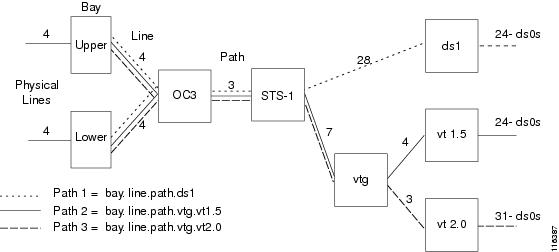
The bit stream interfaces with VXSM via one of the four physical lines in the OC3 back card. This interface is usually in the upper bay (but, when a redundant back card is used and is active, it is in the lower bay).
For a particular line, the OC3 stream consists of three paths and, depending upon the format, a path consists of either 7 virtual tributary groups (vtg) or 28 DS1s. A vtg can be further divided into either four virtual tributaries (version 1.5) or three virtual tributaries (version 2.0). The DS1 and the virtual tributaries (vt) consist of 24 T1 DS0s for T1 or 31 DS0s for E1.
As shown in the diagram, the relationship between DS0s and physical ports can take one of three paths. The paths are common between the physical line and STS-1 level. From the STS-1 level to the DS0, one of three paths can be taken.
The path that a particular DS1/DS0 will use can be configured by the user with the -payload parameter in the cnfpath -sts command. This parameter can be set to:
•![]() 3 = ds3 (not applicable to SDH interface)—The path is carrying a DS3 payload.
3 = ds3 (not applicable to SDH interface)—The path is carrying a DS3 payload.
•![]() 4 = vt15vc11—The path is carrying a SONET-VT1.5/SDH-VC11 payload.
4 = vt15vc11—The path is carrying a SONET-VT1.5/SDH-VC11 payload.
•![]() 5 = vt20vc12—The path is carrying a SONET-VT2/SDH-VC12 payload.
5 = vt20vc12—The path is carrying a SONET-VT2/SDH-VC12 payload.
Note ![]() The vt1.5 path and the vt2.0 path also support SDH-VC11 and SDH-VC12 interfaces respectively.
The vt1.5 path and the vt2.0 path also support SDH-VC11 and SDH-VC12 interfaces respectively.
Using the system described above, DS1 paths in VXSM commands are formatted as follows:
•![]() SONET path payload type VT1.5 or VT2.0
SONET path payload type VT1.5 or VT2.0
The DS1 is specified as: bay.line.path.vtg.vt
bay = 1 (upper bay)
line = the line number on the associated OC-3 card in the range 1 to 4.
path = the path of the virtual tributary in the range 1 to 3.
vtg = the virtual tributary groups applicable to the connection in the range 1 to 7.
vt = virtual tributaries in the range 1 to 4 for vt1.5 or 1 to 3 for vt2.0.

vtg = the virtual tributary group.
vt = virtual tributary
•![]() SONET path payload type is ds3.
SONET path payload type is ds3.
The DS1 is specified as: bay.line.path.ds1
bay = upper of lower bay of the VXSM backcard.
line = the line number on the associated OC-3 card in the range 1 to 4.
path = the SONET (STS-1) path payload type as ds3 in the range 1 to 3.
ds1 = the ds1 channel within the ds3 interface in the range 1 to 28.
SDH Systems
The VXSM- 155 card supports voice circuits that are multiplexed according to the Synchronous Digital Hierarchy (SDH) standard. Each OC- 3 line presents the data stream as a 155.52 Mbps Synchronous Transport Module (STM-1).
Figure 3-2 shows the multiplexing paths between STM-1 at the physical line and the T1 or E1 voice circuits.
Figure 3-2 SDH Hierarchical Relationships
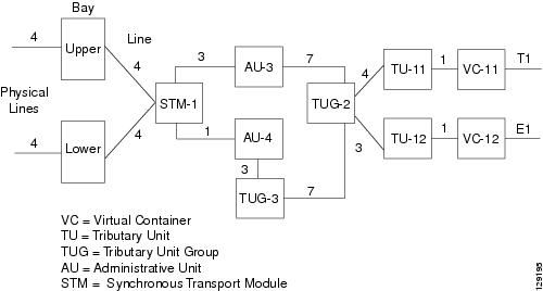
When using the SDH interface, the user must configure the path using the cnfpath -sts command. The format of this command is:
cnfpath -sts <bay.line.path> [-payload <Path Payload>] [-tm <Tributary Mapping Type>]
[-tg <Tributary Grouping>] [-txtrace <Transmit Trace>] [-extrace <Expect Trace>]
<bay.line.path>, specifies the bay (1 = upper), the physical line number on the back card, the path number between the STM and the AU (1, 2, or 3 for AU-3, 1 for AU-4)
-payload <Path Payload>, specifies the TU/VC combination (TU-11/VC-11 for T1 or TU-12/VC-12 for E1).
-tm<Tributary Mapping Type>, specifies the mapping mode, 1 = asynchronous mode or 2 = byteSynchronous mode.
-tg <Tributary Grouping>, specifies the tributary grouping This is a choice between AU-3 or AU-4 (the default).
2 = au3Grouping—Applicable to SDH interfaces: STM1, -AU-3, -TUG-2, -TU-12, -VC12 or STM1, -AU-3, -TUG-2, -TU-11, -VC11.
3 = au4Grouping—Applicable to SDH interfaces: STM1, -AU-4, -TUG-3, -TUG-2, -TU-12, -VC12 or STM1, -AU-4, -TUG-3, -TUG-2, -TU-11, -VC11.
T1/E1 Systems
In T1/E1 systems, the front card supports up to 48 T1 or E1 lines. The back card supports up to 24 T1 or E1 lines. Depending upon the number of lines to be supported, one or two half high back cards are configured using 1 front card; one in the upper or lower bay and the other (if configured) in the remaining open bay.
A physical line or a DS1 service is specified simply as:
bay.line
where:
bay = 1 or 2—1 for the upper bay, 2 for the lower bay.
line = 1 - 24, The physical T1 line on the back card in the range 1 to 24.
If the command requires the interface to be further specified down to the DS0 level, the DS0 is specified as:
bay.line ds0grp
where:
ds0grp = 0 - 23 or 30 — The DS0 group in the range of 0 to 23 for T1 or 0 to 30 for E1.
T3/E3 Systems
In T3/E3 systems, the front card supports up to 6 T3 or E3 lines. The back card supports up to 3 T3 or E3 lines. Depending upon the number of lines to be supported, one or two half height back cards are configured with a single front card; one in the upper or lower bay and other (if configured) in the remaining open bay.
A DS1 is specified simply as:
bay.line.path
where:
bay = 1 or 2—1 for the upper bay, 2 for the lower bay.
line = 1 - 3—The physical T3 line on the back card in the range 1 to 3
path = 1 - 28—The DS1 circuit in the T3 line in the range of 1 to 28
If the command requires the interface to be specified down to the DS0 level, the DS0 is specified as:
bay.line.path ds0grp
where:
ds0grp = 0 - 23 or 30 — The DS0 group in the range of 0 to 23 for T1 or 0 to 30 for E1.
Note ![]() The VXSM T3/E3 card set is designed to support both T3 and E3 applications. However, in Release 5.2 only T3 services are supported.
The VXSM T3/E3 card set is designed to support both T3 and E3 applications. However, in Release 5.2 only T3 services are supported.
Voice Interfaces
A voice interface (VIF) is a user configurable set of parameters that is applied to a group of DS0s within a DS1. The configuration settings of the VIF are used by the digital signal processors (DSPs) to determine how a voice payload is to be processed by VXSM. This is particularly true when the VXSM is operating in VoIP Switching mode.
A voice interface is created using the addvif command. With this command the user specifies a VIF number (DS0 group number) and its associated DS1, in addition, the type of signaling, the type of service (H.248 switching, trunking). Other bearer channel parameters such as echo cancellation and voice activity detection, are also specified, using cnfvifec, cnfvifvad, and other commands as listed below. These parameters are contained within a vif which, when the VIF is added, are assigned default values.
Once a VIF is created, its parameters can be discovered using the dspvif command. There are also display and configure commands for the user to see and configure the various parameters
To create and configure a VIF perform the following steps.
Step 1 ![]() Use the dspvifs command to check that the VIF exists. If it does not, use the addvif command to create the VIF.
Use the dspvifs command to check that the VIF exists. If it does not, use the addvif command to create the VIF.
Step 2 ![]() For a particular DS1, use one of the display VIF commands to display its associated VIF parameter values. Determine which parameter (if any) need to be modified.
For a particular DS1, use one of the display VIF commands to display its associated VIF parameter values. Determine which parameter (if any) need to be modified.
dspvif [<bay.line.path.vtg.vt >] | [<bay.line.path.ds1>] <ds0GroupId> for OC-3
dspvif <bay.line> <ds0GroupId> for 48 T1/E1
dspvif <bay.line.ds1> <Ds0GrpIndex> for T3
dspvifvad <bay.line.path.vtg.vt > | <bay.line.path.ds1> <ds0GroupId> for OC-3
dspvifterms
dspvifterm [< bay.line.path.vtg.vt >] | [<bay.line.path.ds1>] <ds0GroupId> for OC-3
dspvifterm <bay.line> <ds0GroupId> for 48 T1/E1
dspvifterm <bay.line.ds1> <Ds0GrpCfgIndex> for T3
dspvifparam <bay.line> <ds0GroupId> for 48 T1/E1
dspvifparams
dspvifparam <bay.line.ds1> <Ds0GrpCfgIndex> for T3
dspviftoneplan <bay.line> <ds0GroupId> for 48 T1/E1
dspviftoneplan<bay.line> <ds0GroupId> for 48 T1/E1
dspviftoneplan <bay.line.ds1> <Ds0GrpCfgIndex> for T3
dspviftoneplans
dspvifgainattn <bay.line.path.vtg.vt> | <bay.line.path.ds1> <ds0GroupId> for OC-3
dspvifgainattns for OC-3
dspviftd <bay.line.path.vtg.vt> | <bay.line.path.ds1> <ds0GroupId> for OC-3
dspviftds for OC-3
Step 3 ![]() Use any of the following configure vif commands to modify VIF parameters.
Use any of the following configure vif commands to modify VIF parameters.
H.248 Commands
cnfvifec<bay.line.path.vtg.vt > | <bay.line.path.ds1> <ds0GroupId> <EchoCancelEnable>
<EchoCancelCoverage> <Repetition>
cnfvifeventmapping <bay.line.path.vtg.vt> | <bay.line.path.ds1> <ds0GroupId> <EventMappingIndex>
cnfvifgainattn<bay.line.path.vtg.vt> | <bay.line.path.ds1> <ds0GroupId><InputGain><outputAttn><repetition>
cnfviftd <bay.line.path.vtg.vt> | <bay.line.path.ds1> <ds0GroupId><InitDigitTimeout><InterDigitTimeout><repetition>c
cnfvifparam <specified ds1> <ds0GroupId> <NoiseRegEnable> <NonLinearProcEnable> <MusicOnHoldThreshold> <ModemPassThru> <UpspeedCodec> <Repetition>
cnfvifterm <specified ds1> <ds0GroupId> <gatewayLinkId> <packageIds> <profileId>
cnfviftoneplan <specified ds1> < ds0GroupId> <tonePlanId>
cnfvifvad<bay.line.path.vtg.vt > | <bay.line.path.ds1> <ccasGrpCfgIndex> <VAD> <VadTimer>
<Repetition>
TGCP Commands
cnfvifec <bay.line.path.vtg.vt > | <bay.line.path.ds1> <ds0GroupId> <EchoCancelEnable>
<EchoCancelCoverage> <Repetition>
cnfvifeventmapping <bay.line.path.vtg.vt> | <bay.line.path.ds1> <ds0GroupId> <EventMappingIndex>
cnfvifgainattn<bay.line.path.vtg.vt> | <bay.line.path.ds1> <ds0GroupId><InputGain> <outputAttn><repetition>
cnfvifparam<specified ds1> <ds0GroupId> <NoiseRegEnable> <NonLinearProcEnable> <MusicOnHoldThreshold> <Repetition>
cnfviftd <bay.line.path.vtg.vt> | <bay.line.path.ds1> <ds0GroupId><InitDigitTimeout><InterDigitTimeout><repetition>(Only applicable when service is xgcp)
cnfvifvad<bay.line.path.vtg.vt > | <bay.line.path.ds1> <ccasGrpCfgIndex> <VAD> <VadTimer>
<Repetition>
cnfvifxgcpprof<bay.line.path.vtg.vt > | <bay.line.path.ds1> <sd0GroupId> <XgcpProfileIndex>
<Repetition>
See the chapters entitled VXSM Commands for a description of the commands listed in steps 2 and 3.
Configuring TDM Lines
Use the following steps to configure the TDM lines on the VXSM.
Step 1 ![]() Use the upln command to bring up a VXSM line.
Use the upln command to bring up a VXSM line.
upln <bay.line>
For bay, enter 1 for upper bay or 2 for upper bay.
For line, enter a value in the range 1 - 4 for OC-3, 1 - 24 for 48T1/E1, 1 - 3 for T3.
Step 2 ![]() For OC-3 cards, use the uppath command to specify the STS-1 path within the OC-3
For OC-3 cards, use the uppath command to specify the STS-1 path within the OC-3
uppath -sts<bay.line.path>
For bay, enter 1 for upper bay or 2 for lower bay.
For line, enter a value between 1 and 4 to indicate the physical OC-3 interface on the back card.
For path, enter a value between 1 and 3 to indicate the DS3 path within the OC-3 interface.
Step 3 ![]() For OC-3 cards, use the -payload parameter in the cnfpath -sts command to specify the ds1 path with the OC-3. The choices are ds3, vt1.5, and vt2.0.
For OC-3 cards, use the -payload parameter in the cnfpath -sts command to specify the ds1 path with the OC-3. The choices are ds3, vt1.5, and vt2.0.
cnfpath -sts<bay.line.path>[-payload <PathPayload>][-tm <TributaryMappingType>][-tg
<TributaryGroupingType>][-txtrace <PathTraceToTransmit>][-exptrace <PathTraceToExpect]
<bay.line.path>
bay: 1
line: 1 - 4
path: 1 - 3 or 1 (AU4 only)
[-payload <PathPayload>]
3 - ds3
4 - vt15vc11
5 - vt20vc12
[-tm <TributaryMappingType>]
1 - asynchronous
2 - byteSynchronous (NA for ds3)
[-tg <TributaryGroupingType>]
1 - not Applicable (Sonet)
2 - au3Grouping (SDH)
3 - au4Grouping (SDH)
[-txtrace <PathTraceToTransmit>]
trace-string: size 16(SDH) or 64(Sonet)
[-exptrace <PathTraceToExpect]
trace-string: size 16(SDH) or 64(Sonet)
Step 4 ![]() For OC-3 cards, use the uppath command to specify the DS1 path within the DS3
For OC-3 cards, use the uppath command to specify the DS1 path within the DS3
uppath -ds1<bay.line.path.vtg/ds3.vt/ds1>
For bay, enter 1 for upper bay or 2 for upper bay.
For line, enter a value between 1 and 4 to indicate the physical OC-3 interface on the back card.
For path, enter a value between 1 and 3 to indicate the DS3 path within the OC-3 interface.
Step 5 ![]() Use the appropriate addvif command to add a voice interface for a DS0 group within a DS1.
Use the appropriate addvif command to add a voice interface for a DS0 group within a DS1.
For OC-3 use, addvif <bay.line.path.vtg.vt> | <bay.line.path.ds1> <Ds0GrpIndex> <Ds0BitMap> <ServiceType> <Repetition>
For T1/E1 use, addvif <bay.line> <ds0GrpIndex> <ds0ChannelBitMap> <ServiceType> <Repetition>
For T3 use, addvif <bay.line.ds1> <ds0GrpIndex> <ds0ChannelBitMap> <ServiceType> <Repetition>
LineNum for OC-3—(bay.line.path.vtg.vt or bay.line.path.ds1)
bay {1 - upper}
line (range=1º4)
path (range=1º3)
vtg (range=1º7)
vt (range=1º4)(ds1) (range=1º3)(e1)
ds1 (range=1º28)
LineNum for T1/E1—(bay.line)
bay {1 - upper, 2 - lower}
line (range=1º24)
LineNum for T3—(bay.line.ds1)
bay {1 - upper, 2 - lower}
line (range=1º3)
ds1 (range=1º28)
Ds0GrpIndex—DS0 group index
T1: (range=0º23)
E1: (range=0º30)
Ds0BitMap—DS0 channel number
For trunking Service or DS0Xconn: single bit input
For H248: multiple bits input (1-24 or 1, 5, 10-20)
T1: 1,2,3,º24
E1: 1,2,3,º31
ServiceType—service type
For H.248 Protocol, 8 = Trunking, 9 = H248, 10 =DS0Xconn
For xGCP protocol, 8 = Trunking, 10 = DS0Xconn, 11 = xGCP
BulkProvisionNumber—bulk provisioning number
Single DS0 configuration (range=1º8064(O-C3)/1152(T1)/1488(E1))(default=1)
Multiple DS0 configuration (range=1º336(OC-3)/48(T1E1))(default=1)
Setting Up VXSM Connections
Creating a VXSM Resource Partition
Step 1 ![]() Use the addrscprtn command to create a resource partition for the VXSM card.
Use the addrscprtn command to create a resource partition for the VXSM card.
geteway1.5.VXSM.a > addrscprtn <ifNum> <partId> <ctrlrId> <egrminbw> <egrmaxbw> <ingminbw>
<ingmaxbw> <minVpi> <maxVpi> <minVci> <maxVci> <minConns> <maxConns>
For ifNum, enter 1 for port number. For partId, enter 1 for PNNI. For cntrlid, enter 2 for PNNI.
The remaining parameters are used to specify maximum and minimum values for vpi/vci, bandwidth, connections, etc., see the Cisco VXSM Command Reference, Release 5.3 for details.
Creating Slave End Connection on RPM or AXSM Card
Step 2 ![]() For RPM Configurations Only
For RPM Configurations Only
For each connection, specify the slave end on the RPM-XF card and the master end on the VXSM card.
a. ![]() On the RPM-XF card, enter the interface command
On the RPM-XF card, enter the interface command
Router(config)#interface Switch1
b. ![]() On the RPM-XF card, enter the switch connection command to define the slave connection endpoint.
On the RPM-XF card, enter the switch connection command to define the slave connection endpoint.
Router(config-subif)# switch connection vcc <localVPI> <localVCI> master remote raddr
<ATMaddr> <remoteVPI> <remoteVCI>
Omit the <ATMaddr> <remoteVPI> <remoteVCI> parameters
The following example creates a master connection for the PVC labeled VPI 0, VCI 2001:
Router(config-subif)#switch connection vcc 0 2001 master remote
c. ![]() After you create the slave connection endpoint, the RPM-XF enters the switch connection configuration mode and displays the following prompt:
After you create the slave connection endpoint, the RPM-XF enters the switch connection configuration mode and displays the following prompt:
Router(config-if-swconn)#
On the RPM-XF card configure the switch connection using the switch connection configuration commands.
Router(config-if-swconn)rmbs 1024
Router(config-if-swconn)rpcr 860000
Router(config-if-swconn)rscr 860000
Router(config-if-swconn)cpmm-id 9
Router(config-if-swconn)pcr 860000
Router(config-if-swconn)csr 860000
Note ![]() This is the only time that you can configure the switch connection. If you need to change the configuration later, delete the subinterface and recreate the connection.
This is the only time that you can configure the switch connection. If you need to change the configuration later, delete the subinterface and recreate the connection.
d. ![]() To display the ATM address assigned to the slave connection, switch to the active PXM45 card and enter the dspcon command to display connection information. For example, if the RPM-XF is in slot 9
To display the ATM address assigned to the slave connection, switch to the active PXM45 card and enter the dspcon command to display connection information. For example, if the RPM-XF is in slot 9
Router#cc 7
(session redirected)
dspcon 9.1.2.2 0 2000
Port Vpi Vci Owner State
-------------------------------------------------------------------------
Local 9:-1.1:-1 0.2000 SLAVE FAIL
Address: 47.00918100000000036b5e2bb2.000001074b01.00
Remote Routed 0.0 MASTER --
Address: 00.000000000000000000000000.000000000000.00
-------------------- Provisioning Parameters --------------------
Connection Type: VCC Cast Type: Point-to-Point
Service Category: UBR Conformance: UBR.1
Bearer Class: BCOB-X
Last Fail Cause: N/A Attempts: 0
Continuity Check: Disabled Frame Discard: Disabled
L-Utils: 0 R-Utils: 0 Max Cost: 0 Routing Cost: 0
OAM Segment Ep: Enabled
---------- Traffic Parameters ----------
Tx PCR: 353208 Rx PCR: 353208
Tx CDV: N/A Rx CDV: N/A
Tx CTD: N/A Rx CTD: N/A
The slave endpoint ATM address appears below the Local port identification. Note this value because this is the address you need to enter when you create a master connection endpoint at the VXSM card. The connection state is FAIL because the master endpoint has not been created.
e. ![]() Repeat Step 2 until all the bearer (up to 8) and the one control slave ends have been configured.
Repeat Step 2 until all the bearer (up to 8) and the one control slave ends have been configured.
Step 3 ![]() For AXSM Configurations Only
For AXSM Configurations Only
Create PVC connections between VXSM and AXSM.
For each connection, the user needs to specify the slave end on the AXSM card and the master end on the VXSM.
Log on to the AXSM and use the addcon command to configure the slave end point for establishing a PVC between the VXSM and AXSM. Repeat this command for up to 8 bearer PVCs and 1 control PVC
a. ![]() addcon <ifNum> <vpi> <vci> <service type> <mastership>
addcon <ifNum> <vpi> <vci> <service type> <mastership>
[-casttype <value>] [-slave <NSAP.vpi.vci>] [-lpcr <local PCR>] [-rpcr <remote PCR>]
[-lscr <local SCR>] [-rscr <remote SCR>] [-lmbs <local MBS>] [-rmbs <remote MBS>]
[-cdvt <local CDVT>] [-lcdv <local maxCDV>] [-rcdv <remote maxCDV>] [-lctd <local
maxCTD>] [-rctd <remote maxCTD>] [-cc <OAM
CC Cnfg>] [-stat <Stats Cnfg>] [-frame <frame discard>]
[-mc <maximum cost>] [-lputil <local util>] [-rputil <remote util>] [-slavepersflag
<slavepers>] [-rtngprio <routingPriority>] [-prefrte
<preferredRouteId>] [-directrte <directRoute>]
For ifNum specify 1 as the interface number. For VPI and VCI, specify values in the ranges 0 to 255 and 0 to 65535 respectively. For service type, specify 1 (constant bit rate).
For pvc type, specify 1 (AAL5) for a control connection or a bearer connection.
For appication specify 1 for a control connection or 2 for a bearer connection.
For mastership specify 2 for False (slave).
Omit the -slave parameter. The gateway will assign a value and display it as NSAP.VPI.VCI. The user should note the value and use it when adding the master end of the connection on the VXSM.
Of the remaining optional parameters, enter values or accept the defaults. See the CLI chapter for details.
b. ![]() Repeat Step 3 until all the bearer (up to 8) and the one control slave ends have been configured.
Repeat Step 3 until all the bearer (up to 8) and the one control slave ends have been configured.
Creating Master End Connections on VXSM Card
Step 4 ![]() Log on to the VXSM card
Log on to the VXSM card
a. ![]() Use the addcon command to configure the master end point for establishing a PVC between the VXSM and RPM or AXSM.
Use the addcon command to configure the master end point for establishing a PVC between the VXSM and RPM or AXSM.
addcon <ifNum> <vpi> <vci> <serviceType> <pvcType> <application> <mastership>
[-slave <NSAP.vpi.vci>] [-lpcr <local PCR>] [-rpcr <remote PCR>] [-lscr <local SCR>]
[-rscr <remote PCR>] [-lmbs <local MBS>]º
For ifNum specify 1 as the interface number. For VPI and VCI, specify values in the ranges 0 to 255 and 0 to 65535 respectively. For service type, specify 1 (constant bit rate).
For pvc type, specify 1 (AAL5) for a control connection or a bearer connection.
For appication specify 1 for a control connection or 2 for a bearer connection.
For mastership specify 1 for True (master).
For the -slave parameter, enter the NSAP.VPI.VCI that was noted when configuring the slave end of the connection.
Of the remaining optional parameters, enter values or accept the defaults. These parameters are best set from the master end. See the VXSM Command Reference for details.
b. ![]() Repeat step 4 for each bearer and control PVC configured in the previous step (step 2 or step 3).
Repeat step 4 for each bearer and control PVC configured in the previous step (step 2 or step 3).
Note ![]() PVC connections must be configured such that Connection Admission Control (CAC) mastership/slave follows that of the Connection Mastership/Slave.
PVC connections must be configured such that Connection Admission Control (CAC) mastership/slave follows that of the Connection Mastership/Slave.
Assigning IP Addresses
Step 5 ![]() For each connection (control and bearer), there must be an IP address assigned.
For each connection (control and bearer), there must be an IP address assigned.
a. ![]() Use the addconip command to assign IP addresses to the VXSM connections.
Use the addconip command to assign IP addresses to the VXSM connections.
addconip<IpIndex><PortNum><Vpi><Vci><IpAddr>
<PrefixLength><defaultGwIp>
For IpIndex assign a number in the range 1 to 16. Usually the user would assign 1 to the first IP address being assigned, 2 for the next and so on.
For PortNum, enter the value of 1.
For VPI and VCI, enter the values for the connection for which an IP address is being assigned.
For IPAddr, assign an IP address for the connection.
For PrefixLength, enter the length of the IP prefix.
For DefaultGwIp, specify whether this is to be the default gateway. Enter 1 for yes, or 2 for no.
b. ![]() Repeat step 5 for each bearer and control connection that was configured in step 4.
Repeat step 5 for each bearer and control connection that was configured in step 4.
Configuring MGC Interfaces for Call Control
Perform one of the following procedures below to configure the interface between the Media Gateway (MG) and the Media Gateway Controller (MGC). VXSM supports the ITU H.248 and the xGCP protocols, select the procedure that applies to you application.
For each protocol type, the procedure consists of two basic phases. The first phase sets up MGCs and MGC Groups. The second phase configures the protocol and protocol profile details that are used for the VXSM and the MGC to communicate.
Note ![]() XGCP is a generic term for a family of similar MGC protocols. The protocols in the family are:
XGCP is a generic term for a family of similar MGC protocols. The protocols in the family are:
Simple Gateway Controller Protocol (SGCP)
Media Gateway Controller Protocol (MGCP)
Trunking Gateway Controller Protocol (TGCP).
Gateways Using H.248 MGC Protocol
Setting Up H.248 MGCs and MGC Groups
The following procedure establishes Media Gateway Controller and Media Gateway Controller Group identities, properties, and relationships. Because H.248 applications support up to 12 virtual media gateways (VGWs), this procedure supports the configuration of multiple MGC Groups associated with one physical VXSM board.
Step 1 ![]() Determine the number of VGWs, MGCs, and MGC Groups to be setup. Determine their relationships. The rules are:
Determine the number of VGWs, MGCs, and MGC Groups to be setup. Determine their relationships. The rules are:
•![]() A VXSM card can have up to 12 VGWs (it must have at least one)
A VXSM card can have up to 12 VGWs (it must have at least one)
•![]() There must one, and only one, associated MGC Group for each VGW
There must one, and only one, associated MGC Group for each VGW
•![]() Each MGC Group can up to 4 MGCs (it must have at least one)
Each MGC Group can up to 4 MGCs (it must have at least one)
Figure 3-3 shows a sample arrangement is which VXSM is partitioned into 4 virtual media gateways with 4 corresponding media gateway groups.
Figure 3-3 MGC, MGC Group, and VMG Arrangement—Example

Step 2 ![]() Provide a domain name for the MGC, and specify how it is to be resolved.
Provide a domain name for the MGC, and specify how it is to be resolved.
a. ![]() Use the addmgcdn command to add am MGC domain name.
Use the addmgcdn command to add am MGC domain name.
addmgcdn <MGC Index> <Domain Name>
For MGC Index, enter an integer in the range 1 to 4 to identify the MGC within a group.
For Domain Name, enter and name up to 64 characters.
b. ![]() Use the cnfmgc command to specify the resolution method for the MGC domain name.
Use the cnfmgc command to specify the resolution method for the MGC domain name.
cnfmgc <MGC Index> <Resolution>
Note ![]() Use the cnfmgc command only if the MGC group is not already in an H.248 association (see later)
Use the cnfmgc command only if the MGC group is not already in an H.248 association (see later)
MGC Index specifies which MGC is being configured in the range of 1 to 4.
For Resolution, specify 1 for internal resolution or 2 for external (DNS) resolution.
If internal resolution is specified, use the addmgcip command to specify an IP address for domain resolution.
addmgcip <MGC Index> <MGC IP Index> <MGC IP Address> <Preference>
MGC Index specifies the MGX for which the IP address is being configured.
For MGC IP Index, enter a integer in the range 1 to 4 to uniquely identify the IP address.
For MGC IP Address, enter the IP address to be used for resolving domain names.
For Preference, enter an integer in the range 1 to 8 to indicate the order of preference of IP addresses for the MGC (1 is the highest).
If resolution is external is specified, use the adddnsdn command to specify the domain name of the server.
adddnsdn <Domain Name>
Step 3 ![]() Use to addmgcgrpmgc command to add the MGC to an MGC group. This command adds an MGC to an MGC Group identified by the MGC Group Index. If no such group exists, one is created.
Use to addmgcgrpmgc command to add the MGC to an MGC group. This command adds an MGC to an MGC Group identified by the MGC Group Index. If no such group exists, one is created.
The syntax for this command is:
addmgcgrpmgc <MGC Group Index> <MGC Index> <Preference> <TCP/UDP Port>
Where:
MGC Group Index—MGC group index (range=1º12)
MGC Index—MGC index (range=1º4). This identifies the MGC within the group.
Preference—Preference (range=1º4) (default=1)
TCP/UDP port—Port (range=1024º16383) (default=2944)
Note ![]() Specifying 0 (zero) as the value of this parameter means that there is no specific UDP port, in which case, the UDP port contained in the protocol table will be used.
Specifying 0 (zero) as the value of this parameter means that there is no specific UDP port, in which case, the UDP port contained in the protocol table will be used.
Step 4 ![]() Repeat steps 2 and 3 for each MGC Group to be set up.
Repeat steps 2 and 3 for each MGC Group to be set up.
Configuring H.248 Protocol
Use this procedure if the VXSM is to communicate with the MGC(s) using the H.248 protocol
H.248 protocol configuration consists of:
•![]() Adding an MGC protocol
Adding an MGC protocol
•![]() Configuring an association between a virtual gateway and a media gateway controller group
Configuring an association between a virtual gateway and a media gateway controller group
•![]() Configuring a protocol (H.248) profile
Configuring a protocol (H.248) profile
•![]() Configuring Switch Circuit Network (SCN) termination
Configuring Switch Circuit Network (SCN) termination
•![]() Configuring Packet Data Network (PDN) termination
Configuring Packet Data Network (PDN) termination
•![]() Providing domain names for VMGs
Providing domain names for VMGs
•![]() Bringing up the association
Bringing up the association
Step 1 ![]() Use the addh248assoc command to add an association of a VGW with an MGC group. The syntax for this command is:
Use the addh248assoc command to add an association of a VGW with an MGC group. The syntax for this command is:
addh248assoc <GatewayLinkId> <MgcGroupIndex> <GatewayIpIndex><PortNumber>
<TransportProtocol><MgHeaderAddrType><SrvChgProfile><SrvChgProfileVer>
<MsgTokenType> <dynamicTpktVersion><maxCommandMsgSize>
<maxReplyMsgSize><VmgwDomainName ><mIdUsePort>
GatewayLinkId—The gateway link ID is an integer in the range 1 to 12. GatewayLinkId unique identifies the MG-MGC association or Virtual MG.
MgcGroupIndex—MGC group index (range=1º12)
GatewayIpIndex—gateway IP index (range=1º16)
PortNumber—gateway port number (range=1024º16383)
TransportProtocol—transport protocol {1 | 2 |3 | #}
1—tcp (default)
2—udp
3—sctp
#—default value
MgHeaderAddrType—MG header address type
{(range=1 to 16) | #=current value} (default=1)
SrvChgProfile—Profile name in ServiceChange message (16 chars)
(default=CISCO_TGW)
For example, CISCO_TGW, BT_TGW
SrvChgProfileVer—Profile version (range=1º99)(default=1)
MsgTokenType—Message Token Type {1 | 2 | #}
1—short (default)
2—long
#—default value
DynamicTpktVersion—This object specifies the TPKT header version that is dynamically assigned based on the size of the packet presented to TCP layer.
1 = Enabled
2 = Disabled
maxCommandMsgSize—Maximum command message size in the range of 2K to 64K
# - default value (default is 2)
maxReplyMsgSize - Maximum reply message size in the range of 2K to 64K
# - default value (default is 2)
VmgwDomainName—Domain name for the Virtual Media Gateway. A character string of 1 to 64 characters.
# - default value (NULL) in addh248assoc
mIdUsePort—User port number in the mId. This parameter is valid only if MgHeaderAddrType = dn.
0 = No Port number
1 = Use port number
# = Use current value
Note ![]() The mIdUsePort parameter is used to specify whether the port number is to be included (or not included) as part of the virtual media gateway domain name.
The mIdUsePort parameter is used to specify whether the port number is to be included (or not included) as part of the virtual media gateway domain name.
For example, if the VmgwDomainName parameter is used to assign the domain name of VMGW001 and the port number is specified as 2848, the mId of the virtual media gateway is:
VMGW001 — if mIdUsePort is set to No port number, or
VMGW001:2848 — if mIdUsePort is set to Use port number.
Note ![]() The dsph248assoc and dsph248state commands can be used to display the association parameters. The cnfh248rootpkg and cnfh248delay commands can be used to modify the association parameters. See the CLI chapter for details.
The dsph248assoc and dsph248state commands can be used to display the association parameters. The cnfh248rootpkg and cnfh248delay commands can be used to modify the association parameters. See the CLI chapter for details.
Step 2 ![]() Use the cnfh248param command to configure H.248 protocol related parameters.
Use the cnfh248param command to configure H.248 protocol related parameters.
cnfh248param <GatewayLinkId> <RespRetentionTime> <InitialRtt> <InactivityTime>
GatewayLinkId—The gateway link ID is an integer in the range 1 to 12. GatewayLinkId unique identifies the MG-MGC association or Virtual MG.
RespRetentionTime—Specifies the time in seconds that an H.248 transaction response should be retained before being sent if the gateway receives a repetition of an H.248 transaction that is still being executed.
The value for this parameter is a number in the range from 0 - 65535, with a default value of 30.
InitialRtt—Defines the initial round-trip time in milliseconds for the response to an H.248 transaction. In effect, this parameters reflects the network delay time.
The value for this parameter is a number in the range from 0 - 65535, with a default value of 1000
InactivityTime—Specifies the allowable period of silence in milliseconds between messages from the media gateway controller (MGC) to the media gateway.
The value for this parameter is a number in the range from 0 - 65535, with a default value of 1000.
Step 3 ![]() Use the cnfh248mg command to configure the H.248 protocol. This command is used to modify the gateway port and other parameters to be used for the VMG.
Use the cnfh248mg command to configure the H.248 protocol. This command is used to modify the gateway port and other parameters to be used for the VMG.
cnfh248mg <GatewayLinkId> <PortNumber>
<VmgwDomainName><MgHeaderAddrType><mIdUsePort>
GatewayLinkId --the gateway link ID is an integer in the range 1 to 12. GatewayLinkId unique identifies the MG-MGC association or Virtual MG.
For portNumber, this parameter is the TCP/UDP port number that the MGC uses to communicate with the MG. The permissible value of this parameter is an integer in the range from 1024 - 16383.
VmgwDomainName -- Domain name for the Virtual Media Gateway. A character string of 1 to 64 characters
MgHeaderAddrType -- MG header address type
1 = ipV4
19 = dn
#= Use current value
mIdUsePort --User port number in the mID. This parameter is valid only if MgHeaderAddrType is specified as dn.
0 = No Port number
1 = Use port number
# = Use current value
Note ![]() The mIdUsePort parameter determines whether the port number will be used in conjunction with the domain name in the mId field of H.248 messages.
The mIdUsePort parameter determines whether the port number will be used in conjunction with the domain name in the mId field of H.248 messages.
For example, if the VmgwDomainName parameter is used to assign the domain name of VMGW001 and the port number is specified as 2848, the domain name of the virtual media gateway is:
VMGW001 if mIdUsePort is set to No port number, or
VMGW001:2848 if mIdUsePort is set to Use port number.
Step 4 ![]() Use the addh248prof command to add an H.248 profile.
Use the addh248prof command to add an H.248 profile.
An H.248 profile contains a set of configurations consisting of SCN and PDN termination types. Each profile is identified by a profile ID (ID = 0 is the default).
addh248prof <Index>
Index -- profile index (range=1º25)
Step 5 ![]() If an H.248 name schema for terminations is to be used, it should be configured now and before any terminations are added.
If an H.248 name schema for terminations is to be used, it should be configured now and before any terminations are added.
Use the cnfh248nameschema command to configure the name schema. The configuration consists of enabling/ disabling the name schema feature and, if enabled, specifying prefix names for DS, RTP, and AAL2/SVC termination types.
cnfh248nameschema <DescriptiveName> <DsNamePrefix> <RtpNamePrefix>
DescriptiveName is a parameter that specifies whether the media gateway is to support the descriptive suffix of the name schema for H.248 terminations in the media gateway.
The permissible values of this parameter are:
•![]() 1—Enables the descriptive name suffix for the termination.
1—Enables the descriptive name suffix for the termination.
•![]() 2—Disables the descriptive name suffix (default value) for the termination.
2—Disables the descriptive name suffix (default value) for the termination.
The parameters DsNamePrefix, RtpNamePrefix are characters strings (length depends upon card type) specifying the prefixes for DS, RTP, AAL1/PVC, and AAL2/PVC respectively.
The default values for these prefixes are DS, RTP, AAL1/PVC, and AAL2/PVC respectively.
Step 6 ![]() Configure the terminations for the switch circuit network (SCN) side of VXSM. It is this step that links the VIFs to the H.248 profiles
Configure the terminations for the switch circuit network (SCN) side of VXSM. It is this step that links the VIFs to the H.248 profiles
a. ![]() Check that the addvif command has already been executed to add a DS0 group. If not, use the addvif command to create a DS0 group.
Check that the addvif command has already been executed to add a DS0 group. If not, use the addvif command to create a DS0 group.
b. ![]() Use the cnfvifterm command to configure SCN terminations.
Use the cnfvifterm command to configure SCN terminations.
The syntax for this command is:
cnfvifterm <LineNum> <Ds0GrpIndex> <GatewayLinkId> <H248PkgIds><ProfileIndex>
<Repetition>
Where:
LineNum for OC-3—(bay.line.path.vtg.vt or bay.line.path.ds1)
bay {1 - upper}
line (range=1º4)
path (range=1º3)
vtg (range=1º7)
vt (range=1º4)(ds1) (range=1º3)(e1)
ds1 (range=1º28)
LineNum for T1/E1—(bay.line)
bay {1 - upper, 2 - lower}
line (range=1º24)
LineNum for T3—(bay.line.ds1)
bay {1 - upper, 2 - lower}
line (range=1º3)
ds1 (range=1º28)
Ds0GrpIndex—DS0 group index
T1: (range=0º23)
E1: (range=0º30)
GatewayLinkId—Gateway link ID an integer in the range 1 to 12. GatewayLinkId unique identifies the MG-MGC association or Virtual MG.
H248PkgIds—H248 package IDs {(multiple IDs) | #=current value}
0 - G
4 - DG
5 - DD
6 - CG
8 - CT
11 - TDMC
12 - AN
13 - BCG
15 - SrvTn
19 - Lltr
20 - BCAS
21 - RBS
22 - OSES
23 - AMET
24 - BCASAddr
25 - CASB
26 - GRI
31 - EriTermInfo
33 - CTYP
# - current packagesProfileIndex—profile index
(range=0º25)(default=0)
# - current value}
Repetition—bulk provisioning number
Single DS0 configuration (range=1º8064(OC-3)/1152(T1)/1488(E1)/4032 (T3). (default=1)
Multiple DS0 configuration (range=1º336(OC-3)/48(T1E1))/168 (T3))(default=1)
Step 7 ![]() Configure the terminations for the packet data network (PDN) side of VXSM
Configure the terminations for the packet data network (PDN) side of VXSM
Use the addtermtype -rtp command to add an RTP terminal type.
The syntax for this command is:
addtermtype -rtp <Index> <PackageIds> <ProfileId> <EventMappingIndex>
termTypeId is a unique identifier in the range of 2 to 3.
For termTypePkgIds, enter a 6 hexadecimal value (representing a 3-byte bitmap) to specify the packages to be supported.The supported packages are:
0 - G
4 - DG
5 - DD
6 - CG
9 - NT
10 - RTP
12 - AN
13 - BCG
15 - SrvTn
26 - GRI
27 - RtcpXr
28 - XrBm
30 - DS
32 - Xnq
34 - IPFAX
ProfileId—Termination type profile ID is an integer in the range 0 to 25, with a default value of 0.
EventMappingIndex—Event Mapping Index for IPIP call is an integer in the range 1 to 10, with a default value of 1 (only for IPIP GW).
Step 8 ![]() When the H.248l profile has been created, it can be further configured using one or any of the following commands. The details of these commands are included in Chapter 6. Use the relevant configure H.248 commands one at a time to configure the parameter values.
When the H.248l profile has been created, it can be further configured using one or any of the following commands. The details of these commands are included in Chapter 6. Use the relevant configure H.248 commands one at a time to configure the parameter values.
These commands are shown in Table 3-2.
Step 9 ![]() Use the cnfh248is command to bring the MG to MGC H.248 link into service.
Use the cnfh248is command to bring the MG to MGC H.248 link into service.
cnfh248is <GatewayLinkId>
GatewayLinkId—Gateway link ID is an integer in the range 1 to 12. GatewayLinkId unique identifies the MG-MGC association or Virtual MG.
Step 10 ![]() Use the relevant display commands (for example, dsph248rootpkg) to check for the correct parameter values.
Use the relevant display commands (for example, dsph248rootpkg) to check for the correct parameter values.
Configuring MGC H.248 Profile
An H.248 profile is a set of parameter values that can be applied (as a set) to SCN terminations and PDN termination types. The parameters are applied by specifying the particular profile when SCNs and PDNs are created using the cnfvifterm and addtermtype commands (see Chapter 3). When the VXSM is operating in VoIP switching mode, the H.248 profile that is selected largely determines the processing that the DSPs perform on the voice payload.
To create and configure an H.248 profile, perform the following steps.
Step 1 ![]() If the profile has not already been created, use the addh248prof command to create the profile and assign it an ID (between 1 and 25).
If the profile has not already been created, use the addh248prof command to create the profile and assign it an ID (between 1 and 25).
addh248prof <profileIndex>
Step 2 ![]() Use the dsph248prof command to display the parameter values of the profile to be configured.
Use the dsph248prof command to display the parameter values of the profile to be configured.
Step 3 ![]() Determine which parameters need to be modified.
Determine which parameters need to be modified.
Step 4 ![]() Use the relevant configure H.248 commands in sequence to modify the parameter values.
Use the relevant configure H.248 commands in sequence to modify the parameter values.
These commands are shown in Table 3-3.
Configuring H.248 Congestion and Overload
To configure Congestion and Overload Thresholds, perform the following steps.
Step 1 ![]() Use the cnfrmrsrc command to configure the CPU interval or the CPU threshold for the call admission control (CAC) processing resource in the media gateway, the format of this command is:
Use the cnfrmrsrc command to configure the CPU interval or the CPU threshold for the call admission control (CAC) processing resource in the media gateway, the format of this command is:
cnfrmrsrc -interval <rsrc_id> -interval <ResourceInterval>
For rsrc_id (resource identifier), enter the number 2 for cpuAvg, 12 for CPS, and 14 (call setup delay).
For interval (resource interval), enter an interval, in seconds, in the range or 10 to 300
Step 2 ![]() The previous step can be verified by executing the dsprmrsrc command.
The previous step can be verified by executing the dsprmrsrc command.
To configure H.248 Congestion Control, perform the following steps.
Step 1 ![]() Use the cnfcrrparam command to enable the congestion control feature. The format of this command is:
Use the cnfcrrparam command to enable the congestion control feature. The format of this command is:
cnfcrrparam <enable> <interval>
For enable, enter 1. The H.248 congestion package is enabled and call reduce functions for the VXSM card are activated.
For interval, enter an interval value in the range from 0 - 100 milliseconds, with a default value of 0.
This parameter defines the call renotification interval (in seconds) for the VXSM card to notify the media gateway controller (MGC) of a congestion condition in the gateway. In the event of congestion, the media gateway generates an event notification to the MGC, requesting a percentage reduction in the rate of calls that the MGC attempts to make to the gateway.
A default value of 0 for this parameter means that the media gateway controller (MGC) does not require renotifications.
Step 2 ![]() The previous step can be verified by executing the dspcrrparam command.
The previous step can be verified by executing the dspcrrparam command.
To configure H.248 Overload Control, perform the following steps.
Step 3 ![]() Use the cnfovrldparam command to enable H.248 overload control, the format of this command is:
Use the cnfovrldparam command to enable H.248 overload control, the format of this command is:
cnfovrldparam <overloadEnable>
For overloadEnable, enter a value of 1 to enable the overload feature.
Step 4 ![]() The previous step can be verified by executing the dspovrldparam command.
The previous step can be verified by executing the dspovrldparam command.
Configuring H.248 Transparent RTP IP-IP Connections
The VXSM command Configure DSP Parameters (cnfdspparam) is used to enable or disable the IP-IP transparent mode feature. This command includes an optional -ipip <transparent IP-IP> parameter. The command is applied at the card level and when the -ipip parameter is set to enabled, all non-transcoding IP-IP connections are established in this transparent mode.
Once an IP-IP connection within a context has been established in transparent mode, another conferencing termination cannot be attached to the connection. For this reason, other additional terminations can only be added to the transparent mode IP-IP connection using one-way topology, away from the IP-IP connection.
The format of the cnfdspparam command is:
cnfdspparam [-ptype <Payload Type>] [-control <RTCP Control>]
[-interval <RTCP Transmit Interval>] [-multi <RTCP Recv Multiplier>]
[-vadapt <VAD Adaptive>] [-dtmfpl <DTMF Power Level>] [-dtmfpt DTMF Power Twist>][-rtcptm <RTCP Timer Control>][-vqm <VQM Control>][-xrcontrol <RTCPXR Control>][-xrmulti <RTCPXR Report Freq.>] [-gmin <VQM default minimum gap>][-rext <RTCPXR ext. R factor>][-sest <SES Threshold>][-ipip <transparent IP-IP>]
For ipip -- IPIP mode, the values are as follows:
•![]() 1 - Normal(default)
1 - Normal(default)
•![]() 2 - fastRoute
2 - fastRoute
•![]() 3 - Transparent
3 - Transparent
Configuring H.248 Annexab and Dotted Notation Feature
VXSM supports multiple versions of G.723 and G.729 codecs by using a=fmtp attribute in the SDP body of the outgoing requests. If the values are not set in the fmtp attribute, then the values are determined from the values received from the MGC. In H.248 applications, this feature is enabled using the cnfh248profannexab command.
The format of the cnfh248profannexab command is:
cnfh248profannexab <Index> <AnnexabEnabled>
Where:
Index -- profile index (range=1..25)
AnnexabEnabled -- Annex A&B {1 | 2}
1 - True
2 - False (default)
VXSM also supports encoding and decoding of nonstandard encoding names. If names cannot be derived from the local or the remote descriptor, VXSM sends a standard notation of encoded names. If the encoding name notations are different for local and remote descriptors, then the name specified in the remote descriptor is the preferred name notation. In the H.248 applications, the dotted notation feature is enabled using the cnfh248profcodecnotation command.
The format of the cnfh248profcodecnotation command is:
cnfh248profcodecnotation <Index> <CodecUndottedNotation>
Where:
Index -- profile index (range=1..25)
CodecUndottedNotation -- Undotted Notation {1 | 2}
1 - True (default)
2 - False
To display the current configuration corresponding to annexab and codec notation the following commands are used:
•![]() dsph248profannexab
dsph248profannexab
dsph248profannexab <Profile Index>
•![]() dsph248profcodecnotation
dsph248profcodecnotation
dsph248profcodecnotation <Profile Index>
Gateways Using XGCP MGC Protocol
This section refers to the generic protocol name of XGCP (or xGCP), note that in VXSM Release 5.3 the protocols supported in this generic family are MGCP and TGCP.
Setting Up XGCP Media Gateway Controllers and Media Gateway Controller Groups
The following procedure establishes Media Gateway Controller and Media Gateway Controller Group identities and properties. It also configures MGC and MGC Group relationships.
Step 1 ![]() Provide a domain name for the MGC, and specify how it is to be resolved.
Provide a domain name for the MGC, and specify how it is to be resolved.
a. ![]() Use the addmgcdn command to add a MGC domain name. Repeat for each MGC.
Use the addmgcdn command to add a MGC domain name. Repeat for each MGC.
addmgcdn <MGC Index> <Domain Name>
For MgcIndex, enter an integer in the range 1 to 4 to identify the MGC.
For DomainName, enter and name up to 64 characters.
b. ![]() Use the cnfmgc command to specify the resolution method for the MGC domain name. Repeat for each MGC.
Use the cnfmgc command to specify the resolution method for the MGC domain name. Repeat for each MGC.
cnfmgc <MGC Index> <Resolution>
MGC Index specifies which MGC is being configured in the range of 1 to 4.
For Resolution, specify 1 for internal resolution or 2 for external (DNS) resolution.
c. ![]() If internal resolution is specified, use the addmgcip command to specify an IP address for domain resolution.
If internal resolution is specified, use the addmgcip command to specify an IP address for domain resolution.
addmgcip <MGC Index> <MGC IP Index> <MGC IP Address> <Preference>
MGC Index specifies the MGX for which the IP address is being configured.
For MGC IP Index, enter a integer in the range 1 to 4 to uniquely identify the IP address.
For MGC IP Address, enter the IP address to be used for resolving domain names.
For Preference, enter an integer in the range 1 to 8 to indicate the order of preference of IP addresses for the MGC (1 is the highest).
d. ![]() If external resolution is specified, use the adddnsdn command to add a Domain Name Server (DNS) domain name and the adddnssrver command to add a DNS IP address. The format of these command is:
If external resolution is specified, use the adddnsdn command to add a Domain Name Server (DNS) domain name and the adddnssrver command to add a DNS IP address. The format of these command is:
adddnsdn <domain name>
adddnssrvr <index><ipaddr>
Step 2 ![]() Use the addmgcgrpmgc command to add an MGC to an MGC group. Repeat for each MGC to be included in the group.
Use the addmgcgrpmgc command to add an MGC to an MGC group. Repeat for each MGC to be included in the group.
The syntax for this command is:
addmgcgrpmgc <MGC Group Index> <MGC Index> <Preference> <TCP/UDP Port>
MGC Group Index—MGC group index (range=1º12)
MGC Index—MGC index (range=1º4)
Preference—Preference (range=1º4) (default=1)
TCP/UDP port—Port (range=1024º16383) (default=2944)
Step 3 ![]() Use the cnfxgcpmgcgrp command to configure an MGC group.
Use the cnfxgcpmgcgrp command to configure an MGC group.
The syntax for this command is:
cnfxgcpmgcgrp<MgcgroupNumber>
MgcGroupNumber specifies which MGC Redundant Group will be used in XGCP. An integer in the range 0 to 12.
Two conditions exist for an MGC group:
1. ![]() At least one MGC is associated with the MGC group
At least one MGC is associated with the MGC group
2. ![]() At least one protocol is associated with the MGC group
At least one protocol is associated with the MGC group
XGCP Protocol Configuration
When an MGC is created, the XGCP protocol can be configured using one or any of the following commands (Table 3-4). The details of these commands are included in Chapter 6. Each of the commands has an equivalent display command for displaying the current parameter values.
Configuring an MGC XGCP Profile
An xGCP call control profile contains the call control information that an MGC uses to establish a call. A call control profile contains information such as call agent details (address, port, type, and so on), retry parameters and timeout values.
A voice interface (DS0 group in TDM side) can be associated with a call control profile, in which case all the calls set up in the voice interface will use the call control parameters from the profile.
The following procedure configures a call control profile.
Step 1 ![]() Use the addxgcpprof command to establish a call control profile.
Use the addxgcpprof command to establish a call control profile.
The command has the following syntax:
addxgcpprof<ProfileIndex><profileName>
ProfileIndex uniquely identifies the call control profile. An integer in the range 1 to 30.
profileName is a unique name for the profile. Profile name is a character string of 1 to 30 characters.
Once the profile name is configured it cannot be modified. If a user wants to modify the name. The original profile has to be deleted and another profile created with the new designated name.
Step 2 ![]() When the call control profile has been created, it can be further configured using one or any of the following commands. The details of these commands are included in Chapter 6.
When the call control profile has been created, it can be further configured using one or any of the following commands. The details of these commands are included in Chapter 6.
Each of the commands listed in Table 3-5 has an equivalent display command for displaying the current parameter values.
Configuring CALEA
The VXSM card can be ordered with a firmware image that has the CALEA feature either enabled or disabled. Further, the CALEA features function only in switching VoIP mode using TGCP as the media gateway control protocol.
Step 1 ![]() Check that the CALEA version of the firmware is ordered and installed. Execute the dspcalea command.
Check that the CALEA version of the firmware is ordered and installed. Execute the dspcalea command.
If the response is Unknown Command, the CALEA version is not installed and the feature does not function. If the CALEA version is installed, the dspcalea command shows whether the feature is enabled or disabled.
Step 2 ![]() If the CALEA version of the firmware is installed but is disabled, use the cnfcalea to enable the CALEA feature.
If the CALEA version of the firmware is installed but is disabled, use the cnfcalea to enable the CALEA feature.
Other CALEA commands are:
dspxgcpcalea, this command displays the current status of the CALEA feature (enabled or disabled).
dspxgcpcaleacalls, this command displays details of calls subject to CALEA surveillance.
Configuring MGC Redundancy
MGCs configured in an MGC group form a set of redundant MGCs (up to a maximum of 4). The order in which MGCs are added to the group is the order of preference for selecting the MGC to use. Besides having up to 4 MGCs in a group, each MGC can have up to 4 IP addresses.
The procedure used by VXSM for selecting an MGC is as follows:
1. ![]() VXSM selects the MGC that was first added to the group and uses the highest preference IP address to communicate with the MGC.
VXSM selects the MGC that was first added to the group and uses the highest preference IP address to communicate with the MGC.
2. ![]() If the communication fails, VXSM retries a number of times determined by the value of the xgcpretry parameter.
If the communication fails, VXSM retries a number of times determined by the value of the xgcpretry parameter.
3. ![]() If communication still fails after the retries, VXSM repeats the attempts with the next highest preference IP address.
If communication still fails after the retries, VXSM repeats the attempts with the next highest preference IP address.
4. ![]() If this IP address fails, the next address is attempted, this process continues until all IP addresses are exhausted.
If this IP address fails, the next address is attempted, this process continues until all IP addresses are exhausted.
5. ![]() If none of the IP addresses are able to communicate with the MGC, VXSM repeats the whole process with the second MGC to be added to the MGC group.
If none of the IP addresses are able to communicate with the MGC, VXSM repeats the whole process with the second MGC to be added to the MGC group.
6. ![]() The process continues using the remaining MGCs to establish a connection.
The process continues using the remaining MGCs to establish a connection.
To configure MGC redundancy perform the following steps.
Step 1 ![]() Use the addmgcdn (H.248) command to create an MGC. Create an MGC for each one to be included in the redundant group. Configure them in the order of preference. The first one configured will be the first one used for an MGC. If the first one fails, the second MGC to be configured will be attempted, and so on to a maximum of four.
Use the addmgcdn (H.248) command to create an MGC. Create an MGC for each one to be included in the redundant group. Configure them in the order of preference. The first one configured will be the first one used for an MGC. If the first one fails, the second MGC to be configured will be attempted, and so on to a maximum of four.
Step 2 ![]() Use the addmgcip to specify the IP address or addresses for each MGC.
Use the addmgcip to specify the IP address or addresses for each MGC.
Note ![]() MGCs can be provided with up to four IP address. They should be configured in order of preference. The first address will be tried first, if it fails, the second is attempted, and so on up to four IP addresses.
MGCs can be provided with up to four IP address. They should be configured in order of preference. The first address will be tried first, if it fails, the second is attempted, and so on up to four IP addresses.
Step 3 ![]() Use the addmgcgrpmgc command to add the MGCs to the MGC group. This command also contains the MGC preference parameter.
Use the addmgcgrpmgc command to add the MGCs to the MGC group. This command also contains the MGC preference parameter.
Configuring End Point Service States
Endpoints exist in one of two service states, namely, in-service (IS) and out of service (OOS). The state of an endpoint is determined by user configuration commands and line alarm conditions. When an endpoint is added, it is automatically put into in-service state and, likewise, when an endpoint is deleted it is automatically brought out of service. When the path or line status at the far end is either down or not configured, VXSM generates statistical alarms like UAS-15 and UAS-24 towards the TDM. In order to prevent VXSM from detecting and generating such alarms, the admin status of the physical path or line is configured to down. This feature allows VXSM to configure the administrative status of the path to down, even if the TDM configuration exists for a particular path or line. Endpoints can be configured on VXSM-4-155, 6T3, and 48T1/E1 cards.
Note ![]() VXSM supports endpoint configurations for all the calls in VoIP switching mode configured for H.248 and xGCP applications.
VXSM supports endpoint configurations for all the calls in VoIP switching mode configured for H.248 and xGCP applications.
This feature is not applicable for AAL2 Trunking applications. The execution of dnpath or dnln commands are rejected, if a VIF exists on a path, irrespective of its admin state or the line or path.
Endpoint can be brought into and out of service through the following commands, which operate either on a line by line basis or on the entire path:
•![]() cnflnis — Configure a line as IS
cnflnis — Configure a line as IS
•![]() cnflnoos — Configure a line as OOS
cnflnoos — Configure a line as OOS
•![]() cnfpathis — Configure a path as IS
cnfpathis — Configure a path as IS
•![]() cnfpathoos — Configure a path as OOS
cnfpathoos — Configure a path as OOS
The cnflnoos and cnfpathoos commands support two options—graceful or forced transition.
In case of MGCP, when forced Out of Service (OOS) is applied on path or line; VXSM marks terminations as OOS and sends RSIP with delay timer 0. VXSM then sends DLCX to CA. This call will be deleted immediately after applying cnfpathoos or cnflnoos forced.
In case of H.248, when forced OOS is applied on path or line, VXSM marks terminations as OOS and sends service change to CA. The CA the sends the Subtract to these endpoints so that VXSM can clear the call context. The execution of dnpath or dnln must be delayed till VXSM receives subtract from the CA.
Handling of graceful OOS is the same for both H.248 and MGCP applications, the active calls are not deleted immediately after the execution of the cnfpathoos or cnflnoos <graceful> commands but the admin state of path or line changes to OOS state. So the execution of dnpath or dnln command must be delayed till the call are cleared.
The cnfpathoos command changes the service state of the specified E1/T1 path to out of service state but the administrative status of the path continues to remain up. The implementation of dnpath and dnln commands are modified and allows the user to change the administrative status of the path to down even if signaling call(s) exists or one or more voice interface configuration exists on that path.
To prevent VXSM from generating alarms on the TDM side, perform the following steps in the order listed below:
Step 1 ![]() If a voice interface configuration or active call exists on a path/line, then use the cnfpathoos or cnflnoos command to change the admin state to out of service.
If a voice interface configuration or active call exists on a path/line, then use the cnfpathoos or cnflnoos command to change the admin state to out of service.
Step 2 ![]() Use the dnpath or dnln command to change the administrative status to down.
Use the dnpath or dnln command to change the administrative status to down.
Note ![]() To avoid errors, change the admin state of a path or line to OOS before executing the dnpath or dnln commands.
To avoid errors, change the admin state of a path or line to OOS before executing the dnpath or dnln commands.
The uppath command when executed, changes the administrative status of the path to up.
Step 3 ![]() The cnfpathis command changes the service state of the specified E1/T1 path to in-service. Now calls can be placed on these paths.
The cnfpathis command changes the service state of the specified E1/T1 path to in-service. Now calls can be placed on these paths.
Table 3-6 describes the dnln and dnpath command behaviors on different VXSM cards.
Configuring Backhaul
In switching applications, VXSM is able to extract layer 3 signaling frames from a TDM signaling channels and backhaul them to the media gateway controller for processing (this feature is described in Chapter 2).
When backhauling is employed, two distinct communication channels exist between the media gateway and the media gateway controller. The first is used for the normal call control functions and the second is used for backhauling.
Configuration of a backhauling channel consists of the following major steps:
Step 1 ![]() Establishing a communication link between the VXSM and the media gateway controller. This communication link can is based upon a RUDP (Reliable UDP) session set or RTCP.
Establishing a communication link between the VXSM and the media gateway controller. This communication link can is based upon a RUDP (Reliable UDP) session set or RTCP.
Step 2 ![]() Establishing communication link between VXSM and the voice TDM network. This link can be configured for ISDN Q.931.
Establishing communication link between VXSM and the voice TDM network. This link can be configured for ISDN Q.931.
Configuring the MGC Link
Two configuration procedures, one for RUDP and one for SCTP/DUA, follow. Only one procedure can be used for any media gateway or virtual media gateway. Select the appropriate procedure for the gateway being configured.
Configuring RUDP (for PRI only)
To configure an RUDP session between VXSM and the media gateway controller, perform the following steps.
Step 1 ![]() Establish IP connectivity with the media gateway controllers (see Chapter 2 for details).
Establish IP connectivity with the media gateway controllers (see Chapter 2 for details).
Step 2 ![]() Use the addsesset command to create a session set.
Use the addsesset command to create a session set.
addsesset <set number> <fault tolerant>
set number
Integer value of 1 (currently only session set is supported)
fault tolerant
Integer value
1 = fault tolerant
2 = non-fault tolerant
Step 3 ![]() Use the adddnsdn command to add the domain server domain name
Use the adddnsdn command to add the domain server domain name
adddnsdn <Domain Name>
Step 4 ![]() Use the adddnssrvrip command to add the IP address of the domain server
Use the adddnssrvrip command to add the IP address of the domain server
adddnssrvrip 1 172.29.66.35
Step 5 ![]() Use the addmgcdn command to ass the domain name of the media gateway controller
Use the addmgcdn command to ass the domain name of the media gateway controller
addmgcdn 1 mgc7
Step 6 ![]() Use the addsesgrp command to create each session group
Use the addsesgrp command to create each session group
addsesgrp <group number> <set number> <mgcname>
group number
Integer value of 1 or 2 (specify 1 for non-fault tolerant mode or 2 for fault tolerant mode).
set number
Integer value of 1(only 1 is supported)
mgcname
Domain name of the call agent (a text string of 1-64 characters.
Step 7 ![]() Use the addses command to create each RUDP session. Each session group can have up to four sessions.
Use the addses command to create each RUDP session. Each session group can have up to four sessions.
addses <session number> <group number> <priority> <local port> <remote port>
session number
Integer value (1 to 8)
group number
Integer value (1 or 2)
priority
Integer value in the range of 1 to 4. A lower number means higher priority.
local port
Integer value in the range of 1124 to 65535
remote port
Integer value in the range of 1124 to 65535
Step 8 ![]() For each session that has been created, the session parameters can be further configured using the commands in Table 3-7 (see VXSM Command Reference for CLI details).
For each session that has been created, the session parameters can be further configured using the commands in Table 3-7 (see VXSM Command Reference for CLI details).
Configuring H.248 over SCTP (for PRI and DPNSS)
To configure an SCTP session between a VXSM virtual gateway and the media gateway controller, perform the following steps.
Step 1 ![]() Establish IP connectivity with the media gateway controller(s) (see Chapter 2 for details).
Establish IP connectivity with the media gateway controller(s) (see Chapter 2 for details).
Step 2 ![]() Use the addh248assoc command to add an association of a VGW with an MGC Group. Make sure to specify the gateway to MGC transport protocol as sctp (<TransportProtocol> =3).
Use the addh248assoc command to add an association of a VGW with an MGC Group. Make sure to specify the gateway to MGC transport protocol as sctp (<TransportProtocol> =3).
The syntax for this command is:
addh248assoc <GatewayLinkId> <MgcGroupIndex> <GatewayIpIndex><PortNumber> <TransportProtocol><MgHeaderAddrType><SrvChgProfile><SrvChgProfileVer>
<MsgTokenType> <dynamicTpktVersion><maxCommandMsgSize> <maxReplyMsgSize>
•![]() GatewayLinkId—An integer in the range 1 to 12. GatewayLinkId unique identifies the MG-MGC association or Virtual MG.
GatewayLinkId—An integer in the range 1 to 12. GatewayLinkId unique identifies the MG-MGC association or Virtual MG.
•![]() MgcGroupIndex—MGC group index (range=1º12)
MgcGroupIndex—MGC group index (range=1º12)
•![]() GatewayIpIndex—gateway IP index (range=1º16)
GatewayIpIndex—gateway IP index (range=1º16)
•![]() PortNumber—gateway port number (range=1024º16383)
PortNumber—gateway port number (range=1024º16383)
•![]() TransportProtocol—transport protocol {1 | 2 |3 | #}
TransportProtocol—transport protocol {1 | 2 |3 | #}
–![]() 1—tcp (default)
1—tcp (default)
–![]() 2—udp
2—udp
–![]() 3—sctp
3—sctp
–![]() #—default value
#—default value
•![]() MgHeaderAddrType—MG header address type
MgHeaderAddrType—MG header address type
{(range=1 to 16) | #=current value} (default=1)
•![]() SrvChgProfile—Profile name in service change message (16 characters)
SrvChgProfile—Profile name in service change message (16 characters)
(default=CISCO_TGW)
For example, CISCO_TGW, BT_TGW
•![]() SrvChgProfileVer—Profile version (range=1º99)(default=1)
SrvChgProfileVer—Profile version (range=1º99)(default=1)
•![]() MsgTokenType—Message Token Type {1 | 2 | #}
MsgTokenType—Message Token Type {1 | 2 | #}
–![]() 1—short (default)
1—short (default)
–![]() 2—long
2—long
–![]() #—default value
#—default value
•![]() DynamicTpktVersion—Specifies the TPKT header version that is dynamically assigned based on the size of the packet presented to TCP layer.
DynamicTpktVersion—Specifies the TPKT header version that is dynamically assigned based on the size of the packet presented to TCP layer.
1 = Enabled
2 = Disabled
Step 3 ![]() Use the cnfh248sctpparams command to configure the SCTP parameters. The format is:
Use the cnfh248sctpparams command to configure the SCTP parameters. The format is:
cnfh248sctpparams <SctpIdx>[-rto <InitRto>][-ret <MaxInitRetrans>]
[-minrto <MinRto>][-maxrto <MaxRto>][-asret <MaxAssocRetrans>]
[-ipalive <IPKeepalive>][-ipret <IPPathRetrans>][-tos <TOS>][-instr <InStreams>]
[-outstr <OutStreams>]
For SctpIdx—Enter an SCTP config index number. An integer in the range of 1 to 12.
Enter the following optional parameters as necessary.
For -rto <InitRto>—Enter a maximum initial retransmit timeout in the range of 2000 to 20000 ms. (default=3000)
For -ret <MaxInitRetrans>—Enter a max initial retransmit in the range of 1 to10) (default=8)
For -minrto <MinRto>—Enter a minimum retransmit timeout in the range of 300 to 60000ms (default=300)
For -maxrto <MaxRto>—Enter a max retransmit timeout in the range of 300 to 60000ms. (default=900)
For -asret <MaxAssocRetrans>—Enter a max association retransmit in the range of 2 to 20. (default=5)
For -ipalive <IPKeepalive>—Enter a heart beat interval in the range of 500 to 60000ms. (default=3000)
For -ipret <IPPathRetrans>—Enter the IP path retransmit in the range of 2000 to 20000ms(range=2º10) (default=3)
For -tos <TOS>—Enter the IP precedence level for PDUs in the range of 0 to 255) (default=0)
For -instr <InStreams>—Enter the number of inbound streams for negotiation in the range of 1 to 336) (default=1)
For -outstr <OutStreams>—Enter the number of outbound streams for negotiation in the range of 1 to 336) (default=1)
Configuring the TDM Network Link
Two configuration procedures, one for ISDN layer 2 (LAPD) and one for DPNSS, follow. Only one procedure can be used for any media gateway or virtual media gateway. Select the appropriate procedure for the gateway being configured.
Configuring LAPD
To configure LAPD parameters for a DS0 used for ISDN D channel, perform the following steps.
Step 1 ![]() Use the addlapd command to create an LAPD session on a specified DS0.
Use the addlapd command to create an LAPD session on a specified DS0.
addlapd <bay.line.path.vtg.vt:ds0>|<bay.line.path.ds1:ds0>|<bay.line>:<ds0>[-side
<LAPDside>][-type <Type>][-window <WindowSize>]{-n200<n200>}[-t200 <Timer200>][-t203
<Timer203>][-ds0 <Ds0Format>][-profile <IsdnHdlcProfile>][-as <AS Name>][-appltype
<AppType>]
OC-3/SDH bay.line.path.vtg.vt:ds0 bay {1 - upper}
or bay.line.path.ds1:ds0 line (range=1º4)
path (range=1º3)
vtg (range=1º7)
vt (range=1º4)(ds1)
(range=1º3)(e1)
ds1 (range=1º28)
ds0 (range= 1º24 for T1
1º31 for E1)
T1/E1 bay.line:ds0 bay {1 - upper, 2 - lower}
line (range=1º24)
ds0 (range= 1º24 for T1
1º31 for E1
T3 bay.line.ds1:ds0 bay {1 - upper, 2 - lower}
line (range=1º3)
ds1 (range=1º28)
ds0 (range= 1º24 for T1
1º31 for E1
side <LAPDsid>
Specify whether the LAPD stack is at user side or network side
1 - network
2 - user
-type <Type>
Specify the switch type at the remote end of the ISDN line.
1 - CCITT
3 - AT&T 5ESS PRA
4 - AT&T 4ESS
6 - NT dms100 PRA
7 - VN 2 or VN 3
8 - INS Net
9 - tr6 MPC
10 - tr6 PBX
12 - Austel Primary
13 - National ISDN-1
14 - ETSI
15 - NT dms250
16 - Bellcore
17 - National ISDN-2
-window <WindowSize>
Specify the maximum number of sequentially numbered I-frames that may be outstanding
1º128 (default=7)
-n200 <n200>
Specify the maximum number of retransmissions of a frame
1º10 (default=3)
-t200 <Timer200>
Specify the maximum time to wait for acknowledgment of a transmit frame
100º1023000 ms (default=1000)
-t203 <Timer203>
Specify the maximum time in milliseconds allowed without frames being exchanged. This value should be greater than that for -t200
100º1023000 ms (default=1000)
-ds0 <Ds0Format>
Specify the DS0 format. 56k(1) is robbed-bit for T1.
1—ds056k
2—ds064k}
-profile <IsdnHdlcProfile>
Specify the HDLC profile which contains a list of HDLC attributes for the PRI backhaul connection
1º128
-as <AS Name>
Specify the LAPD application server (AS) name. An AS is a logical entity serving LAPD D-channel.Zero length string (size 0) means there is no AS association with this LAPD D-channel
255 chars. This parameter is used for PRI backhaul using SCTP only and is not configurable for RUDP.
-appltype <AppType>
Specify the PRI backhaul application protocols as 1 or 2.
1 = sctp
2 = rudp
Step 2 ![]() When an LAPD session has been created, the session parameters can be further configured using the following commands (see Chapter 6 for CLI details).
When an LAPD session has been created, the session parameters can be further configured using the following commands (see Chapter 6 for CLI details).
Configuring E911 Emergency Services
Configuration of the E911 feature consists of the following tasks:
•![]() Setting up a CAS variant file for use with the MGC protocol
Setting up a CAS variant file for use with the MGC protocol
•![]() Modify the line signal values (if required)
Modify the line signal values (if required)
•![]() Setting up CAS general configuration parameters (if required)
Setting up CAS general configuration parameters (if required)
•![]() Setting up the CAS line signal timers (if required)
Setting up the CAS line signal timers (if required)
•![]() Setting up a CAS profile (if required)
Setting up a CAS profile (if required)
•![]() Setting up a path and DS1 for E911
Setting up a path and DS1 for E911
•![]() Associating a CAS variant file with a DS1 line and Voice Interface (VIF)
Associating a CAS variant file with a DS1 line and Voice Interface (VIF)
To configure the E911 feature, perform the following procedure.
Step 1 ![]() Set up the CAS variant file
Set up the CAS variant file
a. ![]() Use the dspcasbuiltinvars command to display the available built-in CAS variant files. For example.
Use the dspcasbuiltinvars command to display the available built-in CAS variant files. For example.
M8850_NY.3.VXSM.a > dspcasbuiltinvars
======================================================
======================================================
Built-in CAS Variants (dspcasbuiltinvars)
======================================================
File Name: fgd_os_e911
File Name: fgd_os_psap
File Name: mf_wink_start_incoming
File Name: mf_wink_start_outgoing
File Name: dtmf_wink_start_incoming
File Name: dtmf_wink_start_outgoing
Verify that the var file for E911, fgd_os_e911, is present.
Note ![]() The only other variant file supported by VXSM is mf_wink_start_incoming.o. This file is used for lines that support the Busy Line Verify/Operator Interrupt (BLV/OI) feature.
The only other variant file supported by VXSM is mf_wink_start_incoming.o. This file is used for lines that support the Busy Line Verify/Operator Interrupt (BLV/OI) feature.
b. ![]() Use the addcasvar command to add an E911 variant file. The command has the following format:
Use the addcasvar command to add an E911 variant file. The command has the following format:
addcasvar<CasVarIndx><FileName>[-source<SourceFile>]
For CasVarIndx enter an integer in the range of 1 to 25, use a number to uniquely identify the variant file being added.
For FileName, enter fgd_os_e911. This is the name of the E911 variant file.
For -source <SourceFile>, enter -source 1 for internal.
This instructs VXSM to look for the file as a built-in file in the firmware. Actually, this parameter can be omitted because "internal" is the default value.
The other possible value for this parameter is 2 for external. If this is specified, VXSM looks for the file on the PXM hard disk. External is normally used for testing purposes.
The dspcasvar or dspcasvars commands can be used to verify that the variant file has been added successfully. For example:
M8850_NY.3.VXSM.a > dspcasvars
============================================================================
CAS Variants
============================================================================
VarIndx Variant File Name Source File Variant State Num of Associated
DS0 Group
======= ================= =========== ================ =================
2 fgd_os_e911 internal initSuccessfully 0
3 mf_wink_start_incoming internal initSuccessfully 0
Step 2 ![]() Verify and configure (if necessary) the incoming and outgoing line signal values. The addcasvar command in the previous step populates the default values in the VXSM card for the incoming and outgoing line signals.
Verify and configure (if necessary) the incoming and outgoing line signal values. The addcasvar command in the previous step populates the default values in the VXSM card for the incoming and outgoing line signals.
a. ![]() Use the dspcasinclnsigs and dspcasoutlnsigs commands to display the current values of these parameters. For example:
Use the dspcasinclnsigs and dspcasoutlnsigs commands to display the current values of these parameters. For example:
M8850_NY.3.VXSM.a > dspcasinclnsigs
==============================================================================
Incoming Lines Signal
==============================================================================
Var Sig Signal Name New Old CurTx MinMake MaxMake MinBreak MaxBreak
Index Name Match Match Time Time Time Time
Index Rx Rx (ms) (ms) (ms) (ms)
===== ===== ============== ===== ===== ===== ======= ======= ======== ========
2 1 rx_on_hook 00xx xxxx xxxx 300 300 0 0
2 2 rx_off_hook 11xx xxxx xxxx 50 50 0 0
2 3 rx_wink 11xx xxxx 1111 100 350 70 0
2 4 rx_flash 00xx 11xx xxxx 200 700 0 0
M8850_NY.3.VXSM.a > dspcasoutlnsigs
==================================================================
Outgoing Lines Signal
==================================================================
Var Signal Signal Name Tx Make Break
Index Name Index Pattern Time (ms) Time (ms)
===== ========== ============== ======= ========== ==========
2 1 tx_on_hook 0000 50 0
2 2 tx_off_hook 1111 50 0
2 3 tx_wink 1111 210 50
2 4 tx_flash 0000 400 50
b. ![]() If these line signal values need to be changed, use the cnfcasinclnsig and cnfcasoutlnsig commands.
If these line signal values need to be changed, use the cnfcasinclnsig and cnfcasoutlnsig commands.
The format of the cnfcasinclnsig command is:
cnfcasinclnsig <CasVarIndx> <ILSigIndex> [-minmt <MinMakeTime>] [-maxmt<MaxMakeTime>][-minbt <MinBreakTime>] [-maxbt <MaxBreakTime>]
For CasVarIndx enter an index number to the relevant cas variant entry. The cas variant must have already been added (see previous step).
For ILSigIndex enter an integer in the range of 1 to 25 that uniquely defines the particular set of incoming line signal parameters.
[-minmt <MinMakeTime>] [-maxmt<MaxMakeTime>][-minbt <MinBreakTime>] [-maxbt <MaxBreakTime>] are the minimum and maximum make and break times. Enter a value for each parameter to be configured as follows:
-minmt—A number in the range of 50 to 1000 ms in increments of 10
-maxmt—A number in the range of 20 to 2000 ms in increments of 10
-minbt—A number in the range of 0 to 200 ms in increments of 10
-maxmt—A number in the range of 0 to 200 ms in increments of 10
The format of the cnfcasoutlnsig command is:
cnfcasoutlnsig <CasVarIndx> <OLSigIndex> [-mt <MakeTime>] [-bt <BreakTime>]
For CasVarIndx enter an index number to the relevant cas variant entry The cas variant must have already been added (see previous step).
For OLSigIndex enter an integer in the range of 1 to 25 that uniquely defines the particular set of outgoing line signal parameters.
[-mt <MakeTime>] [-bt <BreakTime>] are the make and break times. Enter a value for each parameter to be configured as follows:
-mt—A number in the range of 50 to 2000 ms
-bt—A number in the range of 0 to 200 ms
Step 3 ![]() Verify and Configure (if necessary) the Line Signal Timers.
Verify and Configure (if necessary) the Line Signal Timers.
An entry with default line signal timers is created automatically with an index number of 1. This default set of timers cannot be modified or deleted by the user. However, the user can create a new set of timers with a new index number.
a. ![]() Use the dspcaslnsigtimer command to display the default Line Signal Timer values. The format of this command is:
Use the dspcaslnsigtimer command to display the default Line Signal Timer values. The format of this command is:
dspcaslnsigtimer <LineSigTimerIndex>
For example:
M8850_NY.3.VXSM.a > dspcaslnsigtimer 1
============================================================
CAS Line Signal timer
============================================================
Line Signal Timer Index : 1
Idle Guard Timer (ms) : 10000
Clear Forward Timer (ms) : 120000
Clear Backward Timer (ms) : 120000
Release Guard Timer (ms) : 800
Glare Timer (ms) : 4000
Answer Meter Delay Timer (ms) : 600
Debounce Timer (ms) : 50
Seize Ack Response Timer (ms) : 6000
Delay Between Register and Line Answer (s) : 90
Seize Ack Wait Timer (s) : 15
b. ![]() If any of the values of the Line Signal Timers need to be changed, use the addcaslnsigtimer command to create a new Line Signal Timers entry with a new index number.
If any of the values of the Line Signal Timers need to be changed, use the addcaslnsigtimer command to create a new Line Signal Timers entry with a new index number.
The format of this command is:
addcaslnsigtimer <LineSigTimerIndex> [-ig <IdleGuardTimer>][-cfw <ClearFwdTimer>]
[-cbw <ClearBwdTimer>][-rg <ReleaseGuardTimer>][-gl <GlareTimer>]
[-am <AnswerMeterDelayTimer>][-db <DebounceTimer>][-srsp <SeizeAckRspTimer>]
[-drl <DelayBetRegAnsAndLineAns>][-sdig <SeizeAckToDigitTimer>]
For example:
M8850_NY.3.VXSM.a > addcaslnsigtimer 2 -ig 10000 -cfw 140000 -cbw 140000
The addcaslnsigtimer command adds and configures the CAS timers with index 2, idle guard timer of 10000 ms, clear forward timer of 140000 ms, clear backward timer of 14000 ms. The remaining unspecified timer values are assigned their default values.
Note ![]() Although the default set of timers with index = 1 cannot be modified or deleted, any other sets of timers created by the user can subsequently be modified or deleted using the cnfcaslnsigtimer and delcaslnsigtimer commands.
Although the default set of timers with index = 1 cannot be modified or deleted, any other sets of timers created by the user can subsequently be modified or deleted using the cnfcaslnsigtimer and delcaslnsigtimer commands.
Step 4 ![]() Verify and Configure (if necessary) the CAS General Configuration values.
Verify and Configure (if necessary) the CAS General Configuration values.
An entry with default CAS general configuration values is created automatically with an index number of 1. This default set of values cannot be modified or deleted by the user. However, the user can create a new set of values with a new index number.
a. ![]() Use the dspcasgencfg command to display the default CAS general configuration values. The format of this command is:
Use the dspcasgencfg command to display the default CAS general configuration values. The format of this command is:
dspcasgencfg <GenCfgIndex>
For example:
M8850_NY.3.VXSM.a > dspcasgencfg 1
============================================================================
CAS General Configuration
============================================================================
CAS General Config Index : 1
Glare Policy : rptSzOnGlareTmrExp
Parmameter Source : mib
Register Signaling Mode : compelled
Line Signaling Type : digital
Ring Back Signal Type : wink
Incoming Call High Frequency Power (dBm) : 0
Incoming Call Low Frequency Power (dBm) : -30
Incoming Call Negative Twist Power (dBm) : 7
Incoming Call Positive Twist Power (dBm) : 7
Incoming Call Break Threshold (dBm) : -32
Outgoing Call High Frequency Power (dBm) : -7
Outgoing Call Low Frequency Power (dBm) : 7
Outgoing Call Cadence On Time (ms) : 65
Outgoing Call Cadence Off Time (ms) : 65
Country Code : 000
Echo Cancellation : outgoingHalfEchoRequired
Subscriber Category : subscriberWithoutPriority
Nature Of Circuit : notIncluded
Compelled Signaling Type : enbloc
Tx Digit Order : dnisAni
Digit Detect Mode : mf
Metering Report Interval Threshold (ms) : 10
Start Timer (s) : 16
Long Timer (s) : 16
Short Timer (s) : 4
Long Duration Timer (s) : 100
MGC Timer (ms) : 1000
Digit Type : mf
End Point Directional : bidirectional
Receive Timeout (s) : 0
Initial Delay (s) : 0
Maximum Number Call Party : 0
b. ![]() If any of the values must be changed, use the addcasgencfg command to create a CAS general configuration entry with a new index number. The format of this command is:
If any of the values must be changed, use the addcasgencfg command to create a CAS general configuration entry with a new index number. The format of this command is:
addcasgencfg <GenCfgIndex> [-gp <GlarePolicy>][-ps <ParmSource>]
[-rsig <RegSigMode>][-lsig <LineSigTyp][-rb <RingBackType>][-ihf <IncHiFreqPower>]
[-ilf <IncLoFreqPower>][-int <IncNegTwist>][-ipt <IncPosTwist>]
[-bkth <IncBreakThreshold>][-olf <OutLoFreqPower>][-opt <OutPosTwist>]
[-cadon <OutCadenceOntime>][-cadoff <OutCadenceOfftime>]
[-ccode <CountryCode>][-ecan <EchoCancellation>]
[-subcat <SubscriberCategory>][-natcir <NatureOfCircuit>]
[-compsig <CompelledSigType>][-tdo <TxDigitOrder>][-digdect <DigitDetectMode>]
[-dmp <MeteringRepIntThresh>][-start <StartTimer>][-long <LongTimer>]
[-short <ShortTimer>][-longdur <LongDurationTimer>][-mgctimer <MGCTimer>]
[-digtype <DigitType>][-enptdir <EndPointDirectional>]
[-rxtmout <ReceiveTimeout>][-initdelay <InitialDelay>][-mxnum <MaxNumCallParty>]
For example:
M8850_NY.3.VXSM.a > addcasgencfg 2-gp 2 -ps 2 -lsig 2 -digtype 1
The addcasgencfg command adds and configures the CAS general features with an index =2, all default values are accepted with the exception of glare policy = 2 (OnGlareDetect), parameter source is 2 (MIB), line signaling type is 2 (ring back), and digit select mode is 1 (dtmf):
Note ![]() Although the default CAS general configuration values with index = 1 cannot be modified or deleted, any other sets of values created by the user can subsequently be modified or deleted using the cnfcasgencfg and delcasgencfg commands.
Although the default CAS general configuration values with index = 1 cannot be modified or deleted, any other sets of values created by the user can subsequently be modified or deleted using the cnfcasgencfg and delcasgencfg commands.
Step 5 ![]() Setup a CAS Profile.
Setup a CAS Profile.
A CAS profile is a table entry that specifies which CAS Line Signal Timer entry and which CAS General Configuration entry are to be used. A default CAS profile entry is created automatically that itself has an index of 1 and specifies the CAS Line Signal Timer entry index of 1 and the CAS General Configuration entry index of 1. Thus the default profile specifies the default Line Signal Timers and default CAS General Configuration values.
a. ![]() Use the dspcasprof command to display the default profile.
Use the dspcasprof command to display the default profile.
M8850_NY.3.VXSM.a > dspcasprof 1
==================================================
CAS Profile
==================================================
CAS Profile Index : 1
Line Signal Timer Index : 1
General Config Index : 1
If the user has created new Line Signal Timer or CAS General Configuration entries (as defined in the previous steps), the user can specify the use of these new entries by creating a new CAS profile.
Note ![]() Because the default profile cannot be modified or deleted, the only way to change which Line signal timers and which CAS general configuration values are to be used is to create a new profile.
Because the default profile cannot be modified or deleted, the only way to change which Line signal timers and which CAS general configuration values are to be used is to create a new profile.
To create a new profile, use the addcasprof command. The format of this command is:
addcasprof<ProfIndex> -lstidx<LineSigtimer> -gcidx<GeneralCfg>
Enter a new profile index number for the profile in the range of 2 to 25.
Note ![]() Although the default CAS profile with index = 1 cannot be modified or deleted, any profiles created by the user can subsequently be modified or deleted using the cnfcasprof and delcasprof commands.
Although the default CAS profile with index = 1 cannot be modified or deleted, any profiles created by the user can subsequently be modified or deleted using the cnfcasprof and delcasprof commands.
Step 6 ![]() With the E911 files setup, the next step is to configure one or more DS1 lines as CAS lines for use with E911.
With the E911 files setup, the next step is to configure one or more DS1 lines as CAS lines for use with E911.
Note ![]() This step describes how to configure a DS1 line for CAS E911 purposes. The user can repeat this procedure to configure one or several lines for this purpose but the total (maximum) number of 20 CAS T1 lines per VXSM card (for all applications) must be observed.
This step describes how to configure a DS1 line for CAS E911 purposes. The user can repeat this procedure to configure one or several lines for this purpose but the total (maximum) number of 20 CAS T1 lines per VXSM card (for all applications) must be observed.
a. ![]() Use the upln command to bring up a physical line, the format of this command is:
Use the upln command to bring up a physical line, the format of this command is:
upln <bay.line>
For example:
upln 1.1.
This command brings up line 1 in bay 1 (upper).
b. ![]() Use the uppath -sts command to bring up a SONET path on the upped line, the format of this command is:
Use the uppath -sts command to bring up a SONET path on the upped line, the format of this command is:
uppath -sts <bay.line.path>
For example:
uppath 1.1.1
This command brings up SONET path 1 on line 1 in bay 1 (upper).
c. ![]() Use the uppath -ds1 command to bring up a DS1 line in the SONET path, the format of this command is:
Use the uppath -ds1 command to bring up a DS1 line in the SONET path, the format of this command is:
uppath -ds1 <bay.line.path.vtg.vt >
For example:
uplath 1.1.1.1.1
This command brings up DS1 line 1 on the SONET path 1.
d. ![]() Use the cnfpath -ds1 command to configure the DS1 line for CAS robbed bit signaling, the format of this command is:
Use the cnfpath -ds1 command to configure the DS1 line for CAS robbed bit signaling, the format of this command is:
cnfpath -ds1 <bay.line.path.vtg.vt> | <bay.line.path.ds1> [-lt <LineType>]
[-sc <SendCode>] [-lpb <Loopback>] [-signal <SignalMode>]
[-detect <LoopbackCodeDetection>] [-trkcnd <TrunkConditionEnable>]
[-rep <Repetition>]
The -signal parameter is used to set the signal mode to robbed bit (2), for example:
cnflath 1.1.1.1.1 -signal 2
The DS1 is now configured for CAS robbed bit signaling.
Step 7 ![]() This step creates a voice interface (VIF) for the E911 service and applies the CAS E911 configuration values to that voice interface.
This step creates a voice interface (VIF) for the E911 service and applies the CAS E911 configuration values to that voice interface.
a. ![]() Use the addvif command to create a VIF for the CAS E911 service. The format of this command is:
Use the addvif command to create a VIF for the CAS E911 service. The format of this command is:
addvif <bay.line.path.vtg.vt> | <bay.line.path.ds1> <Ds0GrpIndex> <Ds0BitMap> <ServiceType> <Repetition>
For bay.line.path.vtg.vt |bay.line.path.ds1 specify the same path that has been upped in the previous step.
For Ds0GrpIndex enter a new index number for the Ds0 group. An integer in the range 2 to 23.
For Ds0BitMap enter 1-24 to include all 24 T1 channels in the DS1.
For ServiceType enter the value 11 to indicate the MGC protocol as tgcp.
For repetition enter the value 1.
b. ![]() Use the cnfvifcas command to apply the configured CAS E911 values to the voice interface. The format of this command is:
Use the cnfvifcas command to apply the configured CAS E911 values to the voice interface. The format of this command is:
cnfvifcas <<bay.line.path.vtg.vt> | <bay.line.path.ds1> <Ds0GrpIndex> <CasVariant> <CasProfile>
For <bay.line.path.vtg.vt >|<bay.line.path.ds1><Ds0GrpIndex specify the path and Ds0 group index of the VIF created in the previous sub step.
For CasVariant, enter the index number of the CAS Variant entry to be used. The index number that is specified must already exist.
For CasProfile, enter the index number of the CAS Profile entry to be used. The index number that is specified must already exist.
For example:
cnfvifcas 1.1.1.1.1 1 1 2
This example associates the VIF for path 1.1.1.1.1 Ds0 group 1 with the CAS Variant Index 1 and the CAS Profile index 2
Note ![]() If the application uses H.248 as the media gateway control protocol, the user should follow the cnfvifcas command with the cnfvifterm command. This command sets up the necessary CAS packages for CAS terminations.
If the application uses H.248 as the media gateway control protocol, the user should follow the cnfvifcas command with the cnfvifterm command. This command sets up the necessary CAS packages for CAS terminations.
Configuring Bearer and Signaling Security Features
Configuring the security features consists of the following major steps.
•![]() Setting up security policies.
Setting up security policies.
•![]() Configuring phase 2 signaling security.
Configuring phase 2 signaling security.
•![]() Configuring phase 1 signaling security.
Configuring phase 1 signaling security.
•![]() Configuring the bearer channel.
Configuring the bearer channel.
•![]() Enable security features.
Enable security features.
Note ![]() Bearer and signal security are supported on both the CABLE and TGW firmware images. Bearer security operates with TGCP only. Signal security (IPSec) operates with either H.248 or TGCP.
Bearer and signal security are supported on both the CABLE and TGW firmware images. Bearer security operates with TGCP only. Signal security (IPSec) operates with either H.248 or TGCP.
Setting Up Security Policies
Step 1 ![]() Use the addipsecsp command to create a security policy database table and configure its parameters. The security policy contains a number of selectors that can be matched with those contained in the SDP from the MGC. The matching process determines whether a packet is treated as secure, not secure, or to be discarded.
Use the addipsecsp command to create a security policy database table and configure its parameters. The security policy contains a number of selectors that can be matched with those contained in the SDP from the MGC. The matching process determines whether a packet is treated as secure, not secure, or to be discarded.
The format of this command is:
addipsecsp <SP Index> <Src Addr Prefix Len> <Src Addr> <Dst Addr Prefix Len> <Dst Addr> <SP Protocol> <SP Src Port> <SP Dst Port> <SP Directionality> <SP Mirroring> <SP Action>
For SP Index enter a number in the range of 1 to 12, this number is then used to identify the item in the security policy database table.
For Src Addr Prefix Len enter a number in the range of 1 to 32. This specifies the length of the mask to be used for the source address selector (see below).
For SrcAddr enter an IP (dotted decimal) for the source address selector.
For Dst Addr Prefix Len enter a number in the range of 1 to 32. This specifies the length of the mask to be used for the destination address selector (see below).
For dst Addr enter an IP (dotted decimal) destination address selector.
For SP Protocol enter the transport layer protocol selector.
0 = Any protocol
1 = TCP,
2 = UDP
3 = RAW
For SP Src Port enter the source port selector in the range 1 to 65535. A 0 implies `any port'.
For SP Dst Port enter the destination port selector in the range 1 to 65535. A 0 implies `any port'.
For SP Directionality, enter the inbound (in) or outbound (out) direction for Security Policy Database entries.
1 = In
2 = Out
For SP Mirroring enter whether mirroring or non-mirroring is to be applied.
1 = mirrored
2 = non-mirrored
If mirrored, an entry in the SPD applies to both the inbound and outbound databases with the source, destination addresses and ports reversed.
If non mirrored, an entry added to the SPD applies in the specified direction only.
If mirrored is specified, then it applies to both inbound and outbound databases regardless of the directionality value.
For SP Action enter the action to be taken when a packet matches this policy
1 = secure - Apply IPSec on the packet which matches this policy.
2 = bypass - Do not apply IPSec processing on the packet which it matches this policy.
3 = discard - Drop the packet which matches this policy
The action applicable to a packet after it is selected for one of the three processing modes based on IP and transport layer header information (electors) matched against entries in the SPD.
Note ![]() For signal security to take effect, at least one policy must specify an action of `secure'.
For signal security to take effect, at least one policy must specify an action of `secure'.
Step 2 ![]() Create a separate "Bypass" policy to allow the flow through of DNS traffic.
Create a separate "Bypass" policy to allow the flow through of DNS traffic.
Use the addipsecsp command entering the Media Gateway IP address as the source address and the DNS IP address as the Destination address. Specify the upper layer protocol as UDP (2). This policy stops DNS traffic from being dropped.
Step 3 ![]() Repeat step 2 for any other policies that will be required for the application.
Repeat step 2 for any other policies that will be required for the application.
Configuring Phase 2 Signaling Security
Protecting the signaling link between the MG and MGC involves configuring a number of security parameters such as encryption and authentication algorithms.
Follow the procedures below to configure signal security.
Step 1 ![]() Use the addipsecxform command to enter an item in the IKE Phase 2 Transform table and configure the encryption and authentication algorithms to be supported.
Use the addipsecxform command to enter an item in the IKE Phase 2 Transform table and configure the encryption and authentication algorithms to be supported.
The format of this command is:
addipsecxform <IPSec Transform Index> <IPSec Authentication Header> <IPSec ESP Encryption> <IPSec ESP Authentication> <IPSec Encapsulation Mode>
For IPSec Transform Index, enter the index number to be used in the Phase Transform table. An integer in the range of 1 to 20.
For IPSec Authentication Header (AH), specify the AH Transform applicable to the proposal. Both AH and ESP Transforms cannot be null at the same time.
1 = none
2 = sha196 - SHA1 authentication, first 96 bits used for authentication
3 = md596 - MD5 authentication, first 96 bits used for authentication
For IPSec ESP Encryption, specify the ESP Transform applicable to the proposal.
3 = esp3Des - 3-DES encryption
8 = espNull - ESP encryption in clear text
Only the parameter values of 3 = 3-DES and 8 = NULL are supported.
For IPSec ESP Authentication, specify the Authentication Algorithm for ESP Transform applicable to the proposal.
2 = sha196 - SHA1 authentication - first 96 bits used for authentication
3 = md596 - MD5 authentication - first 96 bits used for authentication.
For IPSec Encapsulation Mode, specify the encapsulation type for the transform enter the value of 1.
1 = transport - IPsec in Transport encapsulation mode
Only the1 = transport mode is supported.
Step 2 ![]() Use the addipsecprop command to add an entry to the IPSec Phase 2 Proposal Table. With this command the user can specify the Diffie Hellman group, the lifetime of the Phase 2, and the lifetime unit.
Use the addipsecprop command to add an entry to the IPSec Phase 2 Proposal Table. With this command the user can specify the Diffie Hellman group, the lifetime of the Phase 2, and the lifetime unit.
The format of this command is:
addipsecprop <Proposal Index> <End Point IP Address> [-antiReplay <Anti Replay>][-pfsEnable <Pfs Enable>][-dhgrp <Diffie Hellman Group>][-unitoftime <Unit of Time>][-hardlifetime <Hard Lifetime>][-select <Use Select>]
For Index enter a number in the range of 1 to 20, this number is then used to identify the item in the Phase 2 Proposal table.
For EndPointIPAddress enter an IP address of the MGC in dotted decimal format. In the case of a Tunnel, the IP Address is that of the router between two end hosts (Gateway).
For -antiReplay<AntiReplay> This parameter specifies whether the Anti-Replay (partial sequence integrity) service to help counter Denial of Service (DoS) attacks is enabled or not. Specify:
1 = Disabled
2 = Enabled
For -pfsEnable<PfsEnable>, this parameter specifies if Perfect Forward Secrecy is enabled or not. Specify:
1 = Enabled
2 = Disabled
For -dhgrp <Diffie Hellman Group>, this parameter. Both Diffie-Hellman groups 1 and 2 are supported for the key exchange process. Specify:
1 = Group 1
2 = Group 2
For -unitoftime<Unit of Time>, this parameter that specifies the units of time for the Phase 2 Lifetime parameter.
1 = seconds
2 = minutes
3 = hours
For -hardlifetime<HardLifetime>, this parameter specifies the time interval when the current SA ends. The unit of this object is dependent on the UnitOfTime parameter.
Enter a number in the range:
60º86400 (seconds)
1º1440 (minutes)
1º24 (hours)
For -select<UseSelect>, this parameter specifies whether the selector parameters are obtained from policy or copied from incoming packet.
1 = Packet
2 = Policy
Step 3 ![]() Repeat step 2 for each other MGCs that VXSM uses for signaling.
Repeat step 2 for each other MGCs that VXSM uses for signaling.
Step 4 ![]() Use the addipsecprxfassoc command to make an association between a proposal entry and a transform entry.
Use the addipsecprxfassoc command to make an association between a proposal entry and a transform entry.
The format of this command is:
addipsecprxfassoc <Index> <IKE Transform Idx>
For Index, specify the index number in the IKE Phase 2 Proposal Table for the proposal entry to be associated. An integer in the range of 1 - 20.
For IKE Transform Idx, specify the index number in the IPSec Ike Phase 2 Proposal Transform table. An integer in the range of 1 - 72.
Step 5 ![]() Use the addipsecspkm command to add an entry to the Policy Database Key Manager Association table. This table contains the mapping between the SPD Table and the Key Manager Table. With this command the user can specify an association between a Security Policy and a Key Manager.
Use the addipsecspkm command to add an entry to the Policy Database Key Manager Association table. This table contains the mapping between the SPD Table and the Key Manager Table. With this command the user can specify an association between a Security Policy and a Key Manager.
The format of this command is:
addipsecspkm <SP Index> <SP Key Mgr Assoc Key Type> <SP Key Mgr Assoc Key Index>
For SP Index, enter the index number to be used in the Policy Database Key Manager Association table. An integer in the range of 1 - 20.
For SP Key Mgr Assoc Key Type, to specify whether IKE or MKM is used for key management for the SPD entry specified. Enter the value of 1 (IKE).
1 = ike - Dynamic method of Key Management through Internet Key Exchange (IKE) protocol.
manual - Manual method of key management (not supported).
For SP Key Mgr Assoc Key Index, to specify the index of the Key Manager table with which the corresponding SPD entry is associated. The index belongs to IKE or MKM tables is determined on the basis of the parameter SP Key Mgr Assoc KeyType An integer in the range of 1 - 72.
Step 6 ![]() Repeat step5 for each other MGCs that VXSM uses for signaling.
Repeat step5 for each other MGCs that VXSM uses for signaling.
Configuring Phase 2 Signaling Security
Step 1 ![]() Use the addipsecikexform to enter an item in the IKE Phase 1 Transform table and configure the encryption and authentication algorithms to be supported.
Use the addipsecikexform to enter an item in the IKE Phase 1 Transform table and configure the encryption and authentication algorithms to be supported.
The format of this command is
:
addipsecikexform <IKE Transform Idx> <IKE Encryption Algo> <IKE Auth Algo>
For IKE Transform Idx enter a number in the range 1 to 10 to identify this record in the IKE Phase 1 Transform table.
For IKE Ecnryption Algo enter the encryption algorithm to be used:
1 = DES
2 = DES3
For IKE Auth Algo enter the authentication algorithm to be used
1 = MD5
2 = SHA.
Step 2 ![]() Use the addipsecikeprop command to enter an item in the IKE Phase 1 Proposal table and to configure proposal parameters.
Use the addipsecikeprop command to enter an item in the IKE Phase 1 Proposal table and to configure proposal parameters.
The format of this command is:
addipsecikeprop <Index> [-dhgrp <Diffie Hellman Group>][-lifetimeunit <Lifetime Unit>][-lifetime <Lifetime>]
For Index enter a number in the range of 1 to 10, this number is then used to identify the item in the Phase 1 Proposal table.
For -dhgrp <Diffie Hellman Group>, this is an optional parameter. Both Diffie-Hellman groups 1 and 2 are supported for the key exchange process. Specify:
1 = Group 1
2 = Group 2
For -lifetimeunit<Lifetime Unit>, an optional parameter that specifies the units of time for the Phase1Lifetime parameter.
1 = seconds
2 = minutes
3 = hours
For -lifetime<Lifetime>, an optional parameter that specifies the time interval when the current IKE Phase 1 Proposal ends. An integer in the range 1 - 65535. The unit is the unit specified in the lifetime unit parameter.
Step 3 ![]() Use the addipsecikeprxfassoc command to make an association between a proposal entry and a transform entry.
Use the addipsecikeprxfassoc command to make an association between a proposal entry and a transform entry.
The format of this command is:
addipsecprxfassoc <Index> <IKE Transform Idx>
For Index, specify the index number in the IKE Phase 1 Proposal Table for the proposal entry to be associated. An integer in the range of 1 - 10.
For IKE Transform Idx, specify the index number in the IPSec Ike Phase 1 Proposal Transform table. An integer in the range of 1 - 10.
Step 4 ![]() Use the addipsecikepeer command to add an entry to the Ike Peer authentication Table. This command also specifies a remote IKE peer, authentication pre shared key information, the proposal to be used, and the authentication method.
Use the addipsecikepeer command to add an entry to the Ike Peer authentication Table. This command also specifies a remote IKE peer, authentication pre shared key information, the proposal to be used, and the authentication method.
addipsecikepeer <IP Config Index> <Remote IP Index> <Remote IP Addr Type> <Remote IP Addr> <Auth Pre Shared Key> <Proposal Index> <Auth Method>
This command. With this command the user can.
For IP Config Index, specify the index for the Ike Peer authentication Table. An integer in the range of 1 - 16
For Remote IP Index, specify the index number of the remote IKE peer. An integer in the range 1 - 16
For Remote IP Addr Type and Remote IP Addr, specify the value 1 (Ipv4) for address type and the address (dotted decimal notation) of the remote peer.
For Auth Pre Shared Key, specify any authentication information in the form of an SNMP admin string of 1 - 64 characters.
For Proposal Index, specify the index in the phase 1 proposal table that defines the proposal to be used to communicate with the peer. An integer in the range 1 - 10.
For Auth Method, specify the authentication method to be used. Enter the value 1 for PSK (Pre Sharing Key).
Configuring Bearer Security
Step 1 ![]() Use the cnfciphersuite -rtp command to configure an entry to the RTP Cipher Suite table. With this command the user can specify the RTP encryption and authentication algorithms available for use with bearer security and the usage preference of those algorithms
Use the cnfciphersuite -rtp command to configure an entry to the RTP Cipher Suite table. With this command the user can specify the RTP encryption and authentication algorithms available for use with bearer security and the usage preference of those algorithms
The format of this command is:
cnfciphersuite -rtp <Encryption Algorithm> <Authentication Algorithm> <Preference>
For Encryption Algorithm, specify an encryption algorithm that may be used for bearer traffic.
1 = Null (no encryption)
2 = AES-128
For Authentication Algorithm, specify an authentication algorithm that may be used for bearer traffic.
1 = Null (no authentication)
2 = MMH2
3 = MMH4
For Preference, specify the preference for the algorithms in this cipher suite.
The entry with the highest preference will be selected first. The entry with '0' preference is not applicable. An integer in the range of 0 to 18.
Note ![]() A combination of null RTP encryption and non-null RTP authentication algorithms is invalid. For example, cnfciphersuite -rtp 1 2 2 would not be valid.
A combination of null RTP encryption and non-null RTP authentication algorithms is invalid. For example, cnfciphersuite -rtp 1 2 2 would not be valid.
Step 2 ![]() Repeat step 1 as necessary to configure additional RTP cipher suites.
Repeat step 1 as necessary to configure additional RTP cipher suites.
Step 3 ![]() Use the cnfciphersuite -rtcp command to configure an entry to the RTCP Cipher Suite table. With this command the user can specify the RTCP encryption and authentication algorithms and the usage preference of those algorithms.
Use the cnfciphersuite -rtcp command to configure an entry to the RTCP Cipher Suite table. With this command the user can specify the RTCP encryption and authentication algorithms and the usage preference of those algorithms.
The format of this command is:
cnfciphersuite -rtcp <Encryption Algorithm> <Authentication Algorithm> <Preference>
For Encryption Algorithm, specify an encryption algorithm that may be used for bearer traffic.
1 = Null (no encryption)
2 = AES-CBC
For Authentication Algorithm, specify an authentication algorithm that may be used for bearer traffic.
1 = Null (no authentication)
2 = HMAC SHA1-96
For Preference, specify the preference for the algorithms in this cipher suite.
The entry with the highest preference will be selected first. The entry with '0' preference is not applicable. An integer in the range of 0 to 18.
Note ![]() A combination of null RTCP encryption and non-null RTCP authentication algorithms is invalid. For example, cnfciphersuite -rtcp 1 2 2 is not valid.
A combination of null RTCP encryption and non-null RTCP authentication algorithms is invalid. For example, cnfciphersuite -rtcp 1 2 2 is not valid.
Step 4 ![]() Repeat step 3 as necessary to configure additional RTCP cipher suites.
Repeat step 3 as necessary to configure additional RTCP cipher suites.
When the ciphersuite configurations have been performed, they can be verified using the dspciphersuite and dspciphersuites commands.
Enable Security Features
Step 1 ![]() Use the addipsecnwif command to add an entry to the Network Interface Table. With this command the user can specify the IP DF (Don't fragment) bit and a PMTU timeout value. These parameters are used for configuring Tunnel mode during IKE phase 2.
Use the addipsecnwif command to add an entry to the Network Interface Table. With this command the user can specify the IP DF (Don't fragment) bit and a PMTU timeout value. These parameters are used for configuring Tunnel mode during IKE phase 2.
The format of this command is:
addipsecnwif <Local IP Index> [-dfbit <DF Bit>][-pmtuage <PMTU age>]
For Local IP Index, enter the index number to be used in the Network Interface Table. An integer in the range of 1 - 16
For -dfbit<DF Bit>, specify whether to clear, set or copy the inner IP header DF (Don't fragment) bit for the Network Interface.
1 = clear - DF bit is not set in the Tunnel IP header (default)
2 = set - DF bit is set in the Tunnel IP header
3 = copy - DF bit is copied from inner IP header to the Outer Tunnel IP header.
For -pmtuage<PMTU age>, specify a timeout value in seconds for PMTU Information for an SA. An integer in the range of 1 - 65535. Default is 10.
Step 2 ![]() Use the cnfbearersec to enable security on the IP bearer traffic.
Use the cnfbearersec to enable security on the IP bearer traffic.
The format of this command is:
cnfbearersec<Security Enable>
For Security Enable, specify:
1 = Enable
2 = Disable
Configuring More Features
In addition to the features described so far in this chapter, there are more VXSM features that can be configured by the user. Refer to Chapter 5 in this guide to see configuration details of these additional features. Some features include:
•![]() Clocking
Clocking
•![]() Connection Admission Control (CAC)
Connection Admission Control (CAC)
•![]() Network Bypass
Network Bypass
•![]() Differentiated Services
Differentiated Services
•![]() Fax/Modem Services
Fax/Modem Services
•![]() Jitter Compensation
Jitter Compensation
 Feedback