- About This Guide
- Cisco Voice Switch Service Module Introduction
- Cisco Voice Switch Service Module Description
- Configuring VoIP Switching Applications
- Configuring Switches for AAL2 Trunking Applications
- Configuring VXSM Features
- VXSM as a Signaling Gateway
- VXSM as a Transcoding Gateway
- Implementing Lawful Intercept on VXSM
- Configuring Lawful Intercept Support
- Loading and Upgrading VXSM Code Images
- VXSM Troubleshooting
- Media Gateway Clocking
- Configuring T1/E1 and T3 Lines
- Configuring SONET Lines and Paths
- Configuring Clocking
- Connection Admission Control
- Configuring Redundancy
- Configuring PRI Backhaul
- Configuring Announcements
- Configuring Network Bypass
- Configuring Differentiated Services
- Configuring Fax and Modem Services
- Configuring Voiceband Event Mapping
- Configuring for V.110 Traffic
- Configuring a Voiceband Data Profiles
- Configuring a TTY Data Profile
- Configuring a T.38 Fax Relay Profile
- Configuring H.248 for Call Agent Controlled T.38 Fax Relay
- Configuring Fax-Relay to Support SG3 Fax Machines at G3 Speeds
- Associating Voice Interfaces with Event Mapping
- Configuring the Voice Quality Monitoring Feature
- Configuring Multiple Bearer IP Pool
- Configuring Online Diagnostic Feature
- Configuring for Jitter Compensation
- DSP Resources Under Mixed Codec Conditions
- DSP RAS and Memory Error Detection
- Configuring Text Over IP
- Configuring RTP Multiplexing
- Configuring DSP Tone Parameters
- Configuring Agere Parameters
- Configuring T.38 Attribute
Configuring VXSM Features
Configuring T1/E1 and T3 Lines
VXSM permits the user to configure many parameters associated with a physical T1, E1, or T3 line. To configure a line:
Step 1 ![]() Use the cnflnoos command to take the line out of service.
Use the cnflnoos command to take the line out of service.
Step 2 ![]() Use the dspln command to display the current configuration of the line, for example
Use the dspln command to display the current configuration of the line, for example
dspln <bay.line>
Step 3 ![]() Determine which parameters need to be changed.
Determine which parameters need to be changed.
Step 4 ![]() Use the cnfln command to change the required parameters.
Use the cnfln command to change the required parameters.
For T1/E1 lines, this command is:
cnfln <bay.line> [< -lt LineType >] [< -sc SendCode >] [< -lpb Loopback >] [< -signal
SignalMode>][< -detect LoopbackCodeDetection >] [< -lc LineCoding >] [< -len LineLength >]
[< -lm LineMod>} [< -lbo LineBuildOut >] [< -rep Repetition >]
For T3 lines, this command is:
cnfln <bay.line> [-lt <LineType>] [-sc <SendCode>] [-lc<LineCoding>] [-len<LineLength>] [-lpb
<Loopback>] [-clock <TxClockSource>]
Step 5 ![]() Use the dspln command to display the new parameter values and verify that they are correct.
Use the dspln command to display the new parameter values and verify that they are correct.
Step 6 ![]() Use the cnflnis command to bring the line into service.
Use the cnflnis command to bring the line into service.
Step 7 ![]() Use the upln command to bring up the line.
Use the upln command to bring up the line.
The BERT (bit error rate testing) and alarm parameters can also be configured for the line using the addbert, cnfbert and cnflnalm commands
Configuring SONET Lines and Paths
VXSM permits the user to configure many parameters associated with a physical SONET line/path.
To configure a SONET line, perform the following procedure.
Step 1 ![]() Use the dnln command to down the OC-3 line
Use the dnln command to down the OC-3 line
Step 2 ![]() Use the dspln command to display the current configuration of the line, for example
Use the dspln command to display the current configuration of the line, for example
dspln n.m (where n is bay and m is the line number)
Step 3 ![]() Determine which parameters need to be changed,
Determine which parameters need to be changed,
Step 4 ![]() Use the cnfln command to change the required parameters.
Use the cnfln command to change the required parameters.
cnfln bay.line [< -slt MediumType >] [< -lpb LoopbackType >] [< -sfs FrameScramble >]
[< -rdiv DIVType >][< -rdip RDIPType >] [< -txtrace TraceToTransmit >]
[< -extrace TraceToExpect >]

Note ![]() The cnfln command configures parameters at the physical OC-3 level only. To configure parameters at the path (ds1) level, use the cnfpath command.
The cnfln command configures parameters at the physical OC-3 level only. To configure parameters at the path (ds1) level, use the cnfpath command.
Step 5 ![]() Use the dspln command to display the new parameter values and verify that they are correct.
Use the dspln command to display the new parameter values and verify that they are correct.
Step 6 ![]() Use the upln command to up the OC-3 line.
Use the upln command to up the OC-3 line.
To configure a SONET path, perform the following procedure.
Step 1 ![]() Use the cnfpathoos command to take the path out of service.
Use the cnfpathoos command to take the path out of service.
Step 2 ![]() Use the dsppath command to display the current configuration of the path, for example
Use the dsppath command to display the current configuration of the path, for example
dsppath [< bay.line.path.vtg.vt >] | [< bay.line.path.ds1>]
Step 3 ![]() Determine which parameters need to be changed.
Determine which parameters need to be changed.
Step 4 ![]() Use the cnfpath command to change the required parameters.
Use the cnfpath command to change the required parameters.
This command has several versions depending upon the path type (ds1, ds3, e1, or sts). As an example, the ds1 version has the format:
cnfpath -ds1 [bay.line.path.vtg.vt] | [bay.line.path.ds1] [-lt <LineType>]
[-sc <SendCode>] [-lpb <Loopback>] [-signal <SignalMode>]
[-detect <LoopbackCodeDetection>] [-rep <Repetition>]
Note ![]() VXSM supports two numbering schemes for mapping DS1 circuits to their vtg/vt values. These two schemes are known as standard and Titan. See next section for details.
VXSM supports two numbering schemes for mapping DS1 circuits to their vtg/vt values. These two schemes are known as standard and Titan. See next section for details.
Step 5 ![]() Use the dsppath command to display the new parameter values and verify that they are correct.
Use the dsppath command to display the new parameter values and verify that they are correct.
Step 6 ![]() Use the cnfpathis to bring the path into service.
Use the cnfpathis to bring the path into service.
VTG/VT to DS1 Mapping Scheme
For applications using the SONET-VT1.5/SDH-VC11 payload path type, VXSM supports two numbering schemes for mapping VTG/VT pairs to DS1s.
The first scheme conforms to ITU-T GR 253 (also Bellcore Std. TR 253) and is referred to as the `standard' scheme.
The second scheme supports certain types of DACS equipment (for example Tellabs 5500 DACS). This scheme is referred to as the Titan scheme (also referred to as the M13 count method).
With this feature, the user can specify which numbering scheme is to be used.
This feature adds two new CLI commands; one to display the currently selected mapping scheme and one to change the mapping scheme.
The SONET-VT1.5/SDH-VC11 payload path type supports 7 VTGs each containing 4 VTs for total of 28 DS1s.
Standard Scheme
In the ITU-T GR.253 spec, the VTG-VT number pairs are incremented such that the VTG number increments from 1-7 before the VT number is incremented. That is, the first VTG-VT pair is 1-1, the second pair is 2-1, the third pair is 3-1, and so on, up to 7-1. The next pair is 1-2, followed by 2-2, 3-2,4-2 º7-2, then 1-3, 2-3º7-3 and so on until 1-4, 2-4º7-4.
Titan Scheme
In the Titan (M13 Count) numbering scheme, VTG-VT number pair are incremented such that the VT increments from 1-4, before the VTG is incremented. That is, the first VTG-VT pair is 1-1, the second pair is 1-2, and so on up to 1-4. The next pair is 2-1, followed by 2-2, 2-3, 2-4, then 3-1, 3-2, 3-3, 3-4 and so on until 7-1, 7-2, 7-3, 7-4.
The complete mapping schemes are shown in Table 5-1.
User Interface
The VTG/VT to DS1 mapping feature uses the following two CLI commands.
•![]() Display VT mapping
Display VT mapping
Syntax: dspvtmapping
This command displays the current setting of VTG/VT to DS1 mapping scheme, values are standard or Titan. Standard denotes ITU-T GR 253, Titan denotes M13 count.
•![]() Configuring VT mapping
Configuring VT mapping
Syntax: cnfvtmapping <VtMappingMode>
1—standard (default)
2—titan
This command switches the current setting of VTG/VT to DS1 mapping scheme to the alternative scheme.
Note ![]() To execute the cnfvtmapping command:
To execute the cnfvtmapping command:
1. The cnfvtmapping command is valid on the VXSMOC-3 card only.
2. All SONET lines on the card must be down.
3. All SONET lines on the card must be configured with medium type as sonet.
4. All SONET paths on the card must be configured as VT1.5.
Note ![]() When VT mapping mode is set to titan, the following commands are affected on the VXSM OC-3 card.
When VT mapping mode is set to titan, the following commands are affected on the VXSM OC-3 card.
cnfln: the option -slt (medium type) are rejected
cnfpath -sts: the options -payload and -tg are rejected
In Titan mode, the DS1 path order will be changed in the following commands (see Table 5-1 for path order).
CLI: dsppaths -ds1
dsppathalms -ds1
dsppathstates (for ds1 only)
dspvif***s (for ds1 only)
dsplapds (for ds1 only)
dspberts -ds1
dspds0xcons (for ds1 only)
Configuring Clocking
The clock for the media gateway can be one of the following sources.
•![]() A BITS clock source received on the PXM-45 back card on ports 35 and 36 using an E1 or T1 RJ-48 connector. In a redundant configuration, a Y-cable is for the BITS clock.
A BITS clock source received on the PXM-45 back card on ports 35 and 36 using an E1 or T1 RJ-48 connector. In a redundant configuration, a Y-cable is for the BITS clock.
•![]() The PXM internal oscillator (stratum 3 circuit on PXM-45 back card)
The PXM internal oscillator (stratum 3 circuit on PXM-45 back card)
•![]() A Clock derived from VXSM line or AXSM line
A Clock derived from VXSM line or AXSM line
The clock source is configured on the active PXM card using the cnfclksrc command.
The syntax of this command is:
cnfclksrc <priority> <portid>[ -bits { e1|t1 } ][ -revertive { enable|disable } ]
where:
priority—This is either primary or secondary (default = primary)
portid—The specification of the port ID depends upon the selected clock source.
If the BITS clock source is selected, portid is specified as:
[shelf.]slot.port
shelf—always 1 and is purely optional.
•![]() slot—the logical slot number 7 for a BITS circuit on the PXM UI S3 (regardless of where the active PXM resides).
slot—the logical slot number 7 for a BITS circuit on the PXM UI S3 (regardless of where the active PXM resides).
•![]() port—a logical number that indicates the upper or lower external clock connector on the UI S3 back card. The logical port number for the upper connector is 35. The lower connector is 36.
port—a logical number that indicates the upper or lower external clock connector on the UI S3 back card. The logical port number for the upper connector is 35. The lower connector is 36.
If a service module line is selected as the source, portid is specified as:
•![]() [shelf.]slot:subslot.port:subport
[shelf.]slot:subslot.port:subport
•![]() shelf—always 1 and optional.
shelf—always 1 and optional.
•![]() slot —the slot number of the service module.
slot —the slot number of the service module.
•![]() subslot—identifies the upper or lower bay of the back card, either a 1 for the upper bay or 2 for the lower bay (default is 1).
subslot—identifies the upper or lower bay of the back card, either a 1 for the upper bay or 2 for the lower bay (default is 1).
•![]() port—is the line number on the service module back card. (The specified line must already be active (see upln).
port—is the line number on the service module back card. (The specified line must already be active (see upln).
•![]() subport—is the logical port number. This value is the logical port (or ifNum) that you must have assigned through addport. Also, the logical port must be known to PNNI (see dsppnports).
subport—is the logical port number. This value is the logical port (or ifNum) that you must have assigned through addport. Also, the logical port must be known to PNNI (see dsppnports).
Note ![]() When specifying a clock source on a VXSM card, the value 10 must be added to both the line and logical port numbers. For example, a primary clock source on a VXSM in slot 3, upper shelf, line 1, logical port 1 would be specified as:
When specifying a clock source on a VXSM card, the value 10 must be added to both the line and logical port numbers. For example, a primary clock source on a VXSM in slot 3, upper shelf, line 1, logical port 1 would be specified as:
cnfclksrc primary 3:1.11:11
•![]() -bits—This keyword parameter is required if slot number 7 and port number of 35 or 36 are specified in portid (indicating BITS as the clock source) Type the string -bits, followed by a space, then either e1 or t1.
-bits—This keyword parameter is required if slot number 7 and port number of 35 or 36 are specified in portid (indicating BITS as the clock source) Type the string -bits, followed by a space, then either e1 or t1.
•![]() -revertive—An option that applies to only the BITS clock. Type the string -revertive, followed by the complete word enable or disable. The default is disable.
-revertive—An option that applies to only the BITS clock. Type the string -revertive, followed by the complete word enable or disable. The default is disable.
Step 7 ![]() Use the cnfclksrc command again to configure the secondary clock source.
Use the cnfclksrc command again to configure the secondary clock source.
Step 8 ![]() Use the cnfclkparms command to configure the signal type and cable type for BITS sources (if applicable). The configuration applies to both (upper and lower) lines.
Use the cnfclkparms command to configure the signal type and cable type for BITS sources (if applicable). The configuration applies to both (upper and lower) lines.
The syntax of this command is:
cnfclkparms <signal type> <cable type>
where:
signal type, 1 = data; 2 = syn (this parameter is not supported in this release)
cable type, 1 = twisted; 2 = coax
Note ![]() E1 lines can be either twisted pair or coaxial cable. T1 lines must always be specified as twisted pair.
E1 lines can be either twisted pair or coaxial cable. T1 lines must always be specified as twisted pair.
Below is an example of a sequence of clock configuration commands.
8850japan.7.PXM.a > cnfclksrc primary 7.35 -bits t1 -revertive enable
8850japan.7.PXM.a > cnfclksrc secondary 7.36 -bits t1 -revertive enable
8850japan.7.PXM.a > cnfclkparms 1 1
Confirm the clock source using the dspclksrc command.
On the PXM card, use the dspclksrcs command to display the clocking configuration.
For example:
8850japan.7.PXM.a > dspclksrcs
Primary clock type: bits t1
Primary clock source: 7.35
Primary clock status: bad
Primary clock reason: no clock
Secondary clock type: bits t1
Secondary clock source: 7.36
Secondary clock status: bad
Secondary clock reason: no clock
Active clock: internal
source switchover mode: revertive
Appendix A in this document covers the subject of clocking in greater detail.
Connection Admission Control
Connection admission control (CAC) is configured when an ATM connection is added using the addcon command. CAC is applied depending upon the values specified for the service type, peak cell rate (PCR), and sustained cell rate (SCR) parameters.
These parameters permit you to specify the bandwidth (expressed as a cell rate) requirements for the virtual circuit being added. If the specified bandwidth is not available, the connection is denied.
The addcon command has four parameters for specifying required cell rate:
•![]() -lpcr
-lpcr
•![]() -rpcr
-rpcr
•![]() -lscr
-lscr
•![]() -rscr
-rscr
–![]() l—Means in the local to remote direction
l—Means in the local to remote direction
–![]() r—Means remote to local direction
r—Means remote to local direction
The four parameters allow the user to specify PCR and SCR values for the PVC in each direction.
If the service type is specified as CBR (constant bit rate), PCR values are used as maximum bandwidth requirements otherwise, SCR values are used as available bandwidth requirements.
To facilitate the CAC function, VXSM performs load balancing on all PVCs configured on the card.
Configuring Redundancy
VXSM provides the following redundancy features.
1:1 Front card/back card redundancy
1:1 APS SONET line redundancy
1+1 APS SONET line redundancy
PVC channel protection
1:1 Front Card/Back Card Redundancy
VXSM front and back cards can be configured for redundancy provided they are installed in adjacent slots (for example, 1 and 2, 9 and 10).
On the PXM card execute the addred command.
addred <redPrimarySlotNum> <redSecondarySlotNum> <redType>
redPrimarySlotNum and redSecondarySlotNum should be specified as the slot number of the active card andthe standby card respectively.
<redType> is redundancy type where redType = 1(1:1 Y-Cable) or 2(1:N). Enter 1 for Y-cable.
APS SONET Line Redundancy
To setup a working/protection line pair, use the addapsln command. This command allows the user to specify an OC-3 port as a working line and a corresponding OC-3 port as a protection line. 1:1, 1+1, and 1+1 Annex B protection types are supported.
To configure 1:1 or 1+1 line redundancy perform the following steps.
Step 1 ![]() Use the addapsln command to setup a working protection line pair.
Use the addapsln command to setup a working protection line pair.
addapsln <working line> <protection line> <archmode>
Working line and protection line are expressed as slot.bay.line.
For working line, slot = physical slot of working line, bay = 1 (upper), line in the range of 1 to 4
For protection line, slot = physical slot of protection line, bay = 1 (upper), line in the range of 5 to 8
For archmode, 1 = (1+1), 2 = (1:1), 3 = (1+1AnxB)
Note ![]() 1+1 and 1+1AnxB are supported on the same card or across 2 card slots. 1:1 is supported only on the same card,.
1+1 and 1+1AnxB are supported on the same card or across 2 card slots. 1:1 is supported only on the same card,.
Step 2 ![]() Use the cnfapsln to configure aps fault thresholds and other parameters.
Use the cnfapsln to configure aps fault thresholds and other parameters.
cnfapsln <working line> [-sf <SigFaultBER>] [-sd <SigDegradeBER>]
[-wtr <WaitToRestore >][-dr <Direction>] [-rv< Revertive>] [-proto <Protocol>]
working and protection lines are expressed as slot.bay.line of the working line (see addapsln above).
SigFaultBER and sigDegradeBER are bit error rates for fault detect and fault degrade detect respectively. If these rates are detected, switchover takes place.
SigFaultBER
This is an integer n in the range from 3 - 5, with a default value of 3. This parameter represents a value of 10-n, where n is 10-3 to 10-5.
sigDegradeBER
This is an integer n in the range from 5 - 9, with a default value of 5. This parameter represents a value of 10-n, where n is 10-5 to 10-9.
Waittorestore
This parameter defines the interval in minutes to wait before attempting to switch back to the working line after a switchover (not applicable if the line is configured in non-revertive mode). The range is 1 to 12 minutes.
The framer clears the signal-fault and signal-degrade states when the APS switchover occurs.
The permissible value of this parameter is an integer in the range from 1 - 12.
Direction
This parameter configures the switching direction that this APS line will support.
1 = Unidirectional—On a failure, only that direction fails over.
2 = Bidirectional—On a failure, both directions fail over.
Revertive
This parameter is used to configure the APS revertive or nonrevertive mode.
1 = Nonrevertive mode—The protection line continues to be the active line. The active line does not switch to the working line.
2 = Revertive mode—Switches the working line back to the active state after the wait-to-restore interval has expired and the working line signal-fault/signal-degrade state has been cleared.
Protocol
This parameter configures the APS channel protocol to be implemented at the near end terminal.
The K1 and K2 overhead bytes in a SONET signal are used as an APS channel to effect the APS protocol.
1 = Bellcore—The APS channel protocol is implemented as defined in the Bellcore document GR-253-CORE.
2 = ITU—The APS channel protocol is implemented as defined in the ITU document G.783, Annex A.
Note ![]() If APS is configured in non-revertive and unidirectional mode, VXSM displays the following behavior on card switchover (active-> standby):
If APS is configured in non-revertive and unidirectional mode, VXSM displays the following behavior on card switchover (active-> standby):
1) If working line is active, after the VXSM switchover, working line will remain active.
2) If protection line is active, after the VXSM switchover, working line will be active provided there are no alarms on the working line. Otherwise, protection line will be active.
PVC Channel Protection
Perform the following procedure to configure a dual PVC pair in which a primary PVC is protected by a secondary PVC.
Step 1 ![]() Create the primary PVC using the addcon command.The -pref parameter is used to specify whether the PVC is a primary, secondary, or none. Specify 1 for primary.
Create the primary PVC using the addcon command.The -pref parameter is used to specify whether the PVC is a primary, secondary, or none. Specify 1 for primary.
Step 2 ![]() Create the secondary PVC using the addcon command.The -pref parameter is used to specify whether the PVC is a primary, secondary, or none. Specify 2 for secondary.
Create the secondary PVC using the addcon command.The -pref parameter is used to specify whether the PVC is a primary, secondary, or none. Specify 2 for secondary.
Note ![]() The primary PVC should be added first and then the secondary. When a PVC is deleted, the secondary should be deleted first. The PCR and SCR values for the primary and secondary PVCs must be the same.
The primary PVC should be added first and then the secondary. When a PVC is deleted, the secondary should be deleted first. The PCR and SCR values for the primary and secondary PVCs must be the same.
Changing the preference of a PVC from secondary to primary or unknown and from primary of unknown to secondary are not allowed. Only primary to unknown and unknown to primary are allowed.
Step 3 ![]() Use the cnfconprotect command to configure the protection.
Use the cnfconprotect command to configure the protection.
cnfconprotect ifNum vpi vci protect fallbackPort fallbackVpi fallbackVci
ifNum
This is the interface number of the PVC, specify 1
vpi, vci
These are the vpi and vci values of the already created PVC.
fallbackPort
This specified whether protection is to applied or not. 1 = protect, 2 = no protection (default).
fallbackVpi, fallbackVci
These are the vpi and vci values of the fallback PVC
Step 4 ![]() Use the cnfoamparams command to configure the operation, administration, and management (OAM) cells for a dual PVC protection group.
Use the cnfoamparams command to configure the operation, administration, and management (OAM) cells for a dual PVC protection group.
cnfoamparams gap retry recover
gap
This parameter defines in milliseconds the inter-cell gap for dual PVC (DPVC) operation, administration, and management (OAM) cells. The permissible range is 20 - 5000, with a default value of 5000.
retry
This parameter defines the retry threshold (in number of cells) during a PVC failure.
When the number of consecutive OAM cells being sent without receiving an acknowledgment (ACK) is equal to the value of this parameter, switchover occurs.
The permissible range is 0 - 20, with a default value of 3.
recover
This parameter defines the threshold (in number of cells) for recovery of a failed PVC.
The permissible range is 0 - 20, with a default value of 5.
When the number of consecutive OAM cells being sent while receiving an acknowledgment (ACK) is equal to the value of this parameter, the failed PVC is considered to have recovered from its failed state.
Note ![]() PVCs cannot be deleted while they are part of a dual PVC protection group and while they are active. To delete a PVC, first use cnfconprotect to set the group to unprotected (fallbackPort = 2). Then use the dncon to make the secondary PVC inactive, delete the secondary PVC and the primary PVC.
PVCs cannot be deleted while they are part of a dual PVC protection group and while they are active. To delete a PVC, first use cnfconprotect to set the group to unprotected (fallbackPort = 2). Then use the dncon to make the secondary PVC inactive, delete the secondary PVC and the primary PVC.
Configuring PRI Backhaul
In switching applications, VXSM is able to extract Q.931 signaling frames from an ISDN PRI D channel and backhaul them to the media gateway controller for processing (this feature is described in Chapter 2). Configuration of this feature consists of the following steps.
Step 1 ![]() Establishing a communication link between the VXSM and the media gateway controller. This communication link can is based upon a RUDP (Reliable UDP) session set.
Establishing a communication link between the VXSM and the media gateway controller. This communication link can is based upon a RUDP (Reliable UDP) session set.
Step 2 ![]() Establishing an LAPD session between VXSM and the voice TDM network.
Establishing an LAPD session between VXSM and the voice TDM network.
Configuring RUDP
To configure an RUDP session between VXSM and the media gateway controller, perform the following steps.
Step 1 ![]() Establish IP connectivity with the media gateway controllers (see Chapter 2 for details).
Establish IP connectivity with the media gateway controllers (see Chapter 2 for details).
Step 2 ![]() Use the addsesset command to create a session set.
Use the addsesset command to create a session set.
addsesset <set number> <fault tolerant>
set number
Integer value of 1 (currently only session set is supported)
fault tolerant
Integer value
1 = fault tolerant
2 = nonfault tolerant
Step 3 ![]() Use the adddnsdn command to add the domain server domain name
Use the adddnsdn command to add the domain server domain name
adddnsdn <Domain Name>
Step 4 ![]() Use the adddnssrvrip command to add the IP address of the domain server
Use the adddnssrvrip command to add the IP address of the domain server
adddnssrvrip 1 172.29.66.35
Step 5 ![]() Use the addmgcdn command to ass the domain name of the media gateway controller
Use the addmgcdn command to ass the domain name of the media gateway controller
addmgcdn 1 mgc7
Step 6 ![]() Use the addsesgrp command to create each session group
Use the addsesgrp command to create each session group
addsesgrp <group number> <set number> <mgcname>
group number
Integer value of 1 or 2 (specify 1 for non-fault tolerant mode or 2 for fault tolerant mode).
set number
Integer value of 1(only 1 is supported)
mgcname
Domain name of the call agent (a text string of 1-64 characters.
Step 7 ![]() Use the addses command to create each RUDP session. Each session group can have up to four sessions.
Use the addses command to create each RUDP session. Each session group can have up to four sessions.
addses <session number> <group number> <priority> <local port> <remote port>
session number
Integer value (1 to 8)
group number
Integer value (1 or 2)
priority
Integer value in the range of 1 to 4. A lower number means higher priority.
local port
Integer value in the range of 1124 to 65535
remote port
Integer value in the range of 1124 to 65535
Step 8 ![]() For each session that has been created, the session parameters can be further configured using the commands in Table 5-2 (see Chapter 6 for CLI details).
For each session that has been created, the session parameters can be further configured using the commands in Table 5-2 (see Chapter 6 for CLI details).
Configuring LAPD
To configure a LAPD parameters for a DS0 used for ISDN D channel, perform the following steps.
Step 1 ![]() Use the addlapd command to create an LAPD session on a specified DS0.
Use the addlapd command to create an LAPD session on a specified DS0.
addlapd <bay.line.path.vtg.vt:ds0>|<bay.line.path.ds1:ds0>|<bay.line>:<ds0>[-side
<LAPDside>][-type <Type>][-window <WindowSize>]{-n200<n200>}[-t200 <Timer200>][-t203
<Timer203>][-ds0 <Ds0Format>][-profile <IsdnHdlcProfile>][-as <AS Name>][-appltype
<AppType>]
Use one of these formats to specify the DS0 on an OC-3 card:
<bay.line.path.vtg.vt:ds0> |<bay.line.path.ds1:ds0>
bay: 1
line: 1 - 4
path: 1 - 3
vtg: 1 - 7
vt: 1 - 4(T1)/3(E1)
ds1: 1 - 28
ds0: 1-24 (T1) 1-16(E1) for RUDP
1-24 (T1) 1-31(E1) for SCTP
Use this format to specify the DS0 on a T1/E1 card
<bay.line>:<ds0>
bay: 1
line: 1 - 4
ds0: 1 - 24 (T1), 1 - 16(E1)
The following parameters are the same for both OC-3 and T1/E1 cards.
side <LAPDsid>
Specify whether the LAPD stack is at user side or network side
1 - network
2 - user
-type <Type>
Specify the switch type at the remote end of the ISDN line.
1 - CCITT
3 - AT&T 5ESS PRA
4 - AT&T 4ESS
6 - NT dms100 PRA
7 - VN 2 or VN 3
8 - INS Net
9 - tr6 MPC
10 - tr6 PBX
12 - Austel Primary
13 - National ISDN-1
14 - ETSI
15 - NT dms250
16 - Bellcore
17 - National ISDN-2
-window <WindowSize>
Specify the maximum number of sequentially numbered I-frames that may be outstanding
1º128 (default=7)
-n200 <n200>
Specify the maximum number of retransmissions of a frame
1º10 (default=3)
-t200 <Timer200>
Specify the maximum time to wait for acknowledgment of a transmit frame
100º1023000 ms (default=1000)
-t203 <Timer203>
Specify the maximum time in milliseconds allowed without frames being exchanged. This value should be greater than that for -t200
100º1023000 ms (default=1000)
-ds0 <Ds0Format>
Specify the DS0 format. 56k(1) is robbed-bit for T1.
1 - ds056k
2 - ds064k}
-profile <IsdnHdlcProfile>
Specify the HDLC profile which contains a list of HDLC attributes for the PRI backhaul connection
1º128 (default = 1)
-as <AS Name>
Specify the LAPD application server (AS) name (12 chars). An AS is a logical entity serving LAPD D-channel.Zero length string (size 0) means there is no AS association with this LAPD D-channel
This parameter is used for PRI backhaul using SCTP only and is not configurable for RUDP.
-appltype <AppType>
Specify the PRI backhaul application protocols as 1 or 2.
1 = sctp (default)
2 = rudp
Step 2 ![]() When an LAPD session has been created, the session parameters can be further configured using the commands in Table 5-3 (see Chapter 6 for CLI details).
When an LAPD session has been created, the session parameters can be further configured using the commands in Table 5-3 (see Chapter 6 for CLI details).
Configuring Announcements
In switching applications VXSM supports the feature in which pre-recorded announcements can be delivered in either direction (to the calling or called party) under the control of the MGC. These announcements can be played during call setup and after the call has been established. The announcement files must be available in the VXSM memory to be played out or, if the file is not resident in VXSM memory, VXSM uses TFTP to obtain the file from an external announcement server, caches it and plays it out.
To configure the Announcements feature, perform the following steps.
Step 1 ![]() It is the responsibility of the user to record all announcements and have them stored in PCM format as computer files in the announcement file server. The announcement file server must IP reachable from the VXSM.
It is the responsibility of the user to record all announcements and have them stored in PCM format as computer files in the announcement file server. The announcement file server must IP reachable from the VXSM.
Step 2 ![]() Use the cnfanndn command to specify the name of the announcement file server.
Use the cnfanndn command to specify the name of the announcement file server.
cnfanndn <ServerDomainName>
Step 3 ![]() Use the cnfanncontrols command to configure announcement parameters.
Use the cnfanncontrols command to configure announcement parameters.
cnfanncontrols [-path <SubDirPath >] [-dn <DomainNameResolution>] [-ip <ipAddress>]
[-age <ageTime>] [-tout <ReqTimeOut >] [-per <maxPermanent>]
SubDirPath is a string up to 64 characters that specifies the subdirectory path to the default TFTP directory in the announcement file server in which the announcement files are stored.
DomainNameResolution specifies how the domain name of the announcement file server is to be resolved.
•![]() 1 = Internal only (default value)—Indicates internal resolution of domain name for announcement file server.
1 = Internal only (default value)—Indicates internal resolution of domain name for announcement file server.
•![]() 2 = External only—Indicates external resolution of domain name for announcement file server.
2 = External only—Indicates external resolution of domain name for announcement file server.
If this parameter is set to the value 1, the IP address associated with the file server is determined according to the value of the -ip ipAddress parameter.
•![]() ipAddress—IP address for the announcement file server. If the DomainNameResolution is configured as external only, this item is ignored.
ipAddress—IP address for the announcement file server. If the DomainNameResolution is configured as external only, this item is ignored.
•![]() ageTime—Time in minutes that an announcement remains valid after it is fetched into the VXSM announcement cache. The range is 1 to 1440. After arriving in the cache, an announcement is not refreshed until it is aged. Subsequent play announcement requests do not affect the agetime or cause the file to be refreshed from the server.
ageTime—Time in minutes that an announcement remains valid after it is fetched into the VXSM announcement cache. The range is 1 to 1440. After arriving in the cache, an announcement is not refreshed until it is aged. Subsequent play announcement requests do not affect the agetime or cause the file to be refreshed from the server.
•![]() ReqTimeOut—Time, in seconds, within which an announcement must start playing after the VXSM receives the announcement signal from the MGC. The default value is 5 seconds.
ReqTimeOut—Time, in seconds, within which an announcement must start playing after the VXSM receives the announcement signal from the MGC. The default value is 5 seconds.
•![]() maxPermanant—Maximum number, in the range 0 to 136, that permanent announcement files can be added to Media Gateway. The default value is 41. A value of 0 indicates that the age time function is disabled.
maxPermanant—Maximum number, in the range 0 to 136, that permanent announcement files can be added to Media Gateway. The default value is 41. A value of 0 indicates that the age time function is disabled.
Step 4 ![]() Use the addannfile to map an announcement name number to the announcement filename. This command also lets you specify the number of times the announcement is to be played, whether the file is to be permanent or not, and the signal duration of the announcement file.
Use the addannfile to map an announcement name number to the announcement filename. This command also lets you specify the number of times the announcement is to be played, whether the file is to be permanent or not, and the signal duration of the announcement file.
addannfile cannoAudioFileNumber FileName [-noc numberOfCycles] [-type fileType]
[-dur signalDuration]
•![]() cannoAudioFileNumber—An index value that identifies the announcement file to be used by the media gateway. The permissible value of this parameter is an integer in the range from 1 - 1024.
cannoAudioFileNumber—An index value that identifies the announcement file to be used by the media gateway. The permissible value of this parameter is an integer in the range from 1 - 1024.
•![]() Filename—Specifies the name of a valid announcement file that has been stored in the media gateway announcement table. This announcement file name, which can be composed of up to 64 characters, can incorporate path or subdirectory information
Filename—Specifies the name of a valid announcement file that has been stored in the media gateway announcement table. This announcement file name, which can be composed of up to 64 characters, can incorporate path or subdirectory information
•![]() noc—Specifies the number of times the announcement file is to be played.
noc—Specifies the number of times the announcement file is to be played.
The permissible value of this parameter is an unsigned integer in the range from 0 - 65535, with a default value of 1.
The value zero specifies that an announcement file is to be played or looped continuously.
type—Specifies the type of the announcement file.
The integer value for this parameter must be one of the following:
–![]() 1 = Dynamic file type (default)—A dynamic file can be removed from cache when the age of the file reaches a specified limit or in accordance with a least recently used (LRU) algorithm when the cache is full.
1 = Dynamic file type (default)—A dynamic file can be removed from cache when the age of the file reaches a specified limit or in accordance with a least recently used (LRU) algorithm when the cache is full.
–![]() 2 = Permanent file type—A permanent file can be stored in cache until it is deliberately deleted.
2 = Permanent file type—A permanent file can be stored in cache until it is deliberately deleted.
This parameter indicates the duration (in milliseconds) that the announcement file is to be played during an announcement cycle. This parameter is applicable only for purposes of playing a fixed announcement.
For fixed announcement play, the -noc numberOfCycles parameter and the -dur signalDuration parameter are used together to determine how long the announcement is to be played.
The permissible value for these parameters is an integer in the range from 0 - 65535.
A value zero for -dur indicates that the duration of the announcement is variable and that the -noc numberOfCycles parameter (see above) will be used to determine play time.
This parameter is used only when the Play Announcement signal from the MGC does not incorporate a parameter specifying the number of cycles that the announcement is to be played.
Step 5 ![]() Use the cnfannfile to configure a specific announcement file.
Use the cnfannfile to configure a specific announcement file.
cnfannfile cannoAudioFileNumber FileName [-noc numberOfCycles]
[-dur signalDuration]
•![]() cannoAudioFileNumber—Index value that identifies the announcement file to be used by the media gateway. The permissible value of this parameter is an integer in the range from 1 - 1024.
cannoAudioFileNumber—Index value that identifies the announcement file to be used by the media gateway. The permissible value of this parameter is an integer in the range from 1 - 1024.
•![]() Filename—Specifies the name of a valid announcement file that has been stored in the media gateway announcement table. This announcement file name, which can be composed of up to 64 characters, can incorporate path or subdirectory information
Filename—Specifies the name of a valid announcement file that has been stored in the media gateway announcement table. This announcement file name, which can be composed of up to 64 characters, can incorporate path or subdirectory information
•![]() noc—Specifies the number of times the announcement file is to be played.
noc—Specifies the number of times the announcement file is to be played.
The permissible value of this parameter is an unsigned integer in the range from 0 - 2147483647, with a default value of 1.
The value zero specifies that an announcement file is to be played or looped continuously.
For fixed announcement play, the -noc numberOfCycles parameter and the -dur signalDuration parameter are used together to determine how long the announcement is to be played.
The permissible value for these parameters is an integer in the range from 0 - 65535.
A value zero for -dur indicates that the duration of the announcement is variable and that the -noc numberOfCycles parameter (see above) will be used to determine play time.
This parameter is used only when the Play Announcement signal from the MGC does not incorporate a parameter specifying the number of cycles that the announcement is to be played.
Configuring Network Bypass
Configuration for the Network Bypass feature consists of making a mesh of PVCs between VXSM and other cards in the gateway. When the mesh of PVCs is complete the feature is enabled through the cnfnwbypass command.
For each PVC in the following procedure the attributes of the PVC are:
•![]() AAL5
AAL5
•![]() PVC type is bearer
PVC type is bearer
•![]() Traffic type: UBR
Traffic type: UBR
•![]() Peak Cell Rate to support 24 OC-3s
Peak Cell Rate to support 24 OC-3s
•![]() No CAC (all internal PVCs run over the shelf's backplane)
No CAC (all internal PVCs run over the shelf's backplane)
•![]() Internal PVCs are not assigned IP addresses
Internal PVCs are not assigned IP addresses
In order to configure the media gateway for the Network Bypass feature, perform the following procedure.
Step 1 ![]() Create a PVC between each VXSM card and its associated RPM or AXS M card. Specify the attributes listed above. The procedure is to configure the slave end at the RPM or AXSM first and the master end on the VXSM second. Details are provided in Chapter 3, the section titled Creating Connections to the RPM-XF Card.
Create a PVC between each VXSM card and its associated RPM or AXS M card. Specify the attributes listed above. The procedure is to configure the slave end at the RPM or AXSM first and the master end on the VXSM second. Details are provided in Chapter 3, the section titled Creating Connections to the RPM-XF Card.
Step 2 ![]() For each VXSM card create one PVC to each of the other VXSM cards in the shelf. Use the addcon command and specify the attributes listed above. It does not matter which is the master and which is the slave.
For each VXSM card create one PVC to each of the other VXSM cards in the shelf. Use the addcon command and specify the attributes listed above. It does not matter which is the master and which is the slave.
Step 3 ![]() For each VXSM card create a single pvc for which the VXSM card is specified for both ends. Use the addcon command and specify the attributes listed above.
For each VXSM card create a single pvc for which the VXSM card is specified for both ends. Use the addcon command and specify the attributes listed above.
Step 4 ![]() By default, the network bypass feature is disabled. To enable the feature, enter the cnfnwbypass command on each VXSM card. The format of this command is:
By default, the network bypass feature is disabled. To enable the feature, enter the cnfnwbypass command on each VXSM card. The format of this command is:
cnfnwbypass <nwbypass>
nwbypass—Has the value 1, 2, or 3
1—disable (default)
2—unconditional enable
3—conditional enable
Conditional enable allows the MGC to control the use of this feature. It can explicitly, in a given call flow, ask for this attribute to be returned.
The current status of the network bypass feature can be shown by entering the dspnwbypass command.
Configuring Differentiated Services
For VoIP applications, VXSM provides support for the quality of service (QoS) feature known as Differentiated Services (Diffserv). The DiffServ feature permits devices at the edge of the network to specify the contents of the Type of Service (ToS) field in the IPv4 header as a differentiated services point code. This point code can then be used by routers in the network to determine per hop behavior (PHB).
VXSM's support of this feature is to permits users to specify the values of the point code to be inserted into the IP header ToS field. The specified values are entered through the cnfiptos command and are applied card-wide. VXSM does not check the entered value nor does it understanding the meaning of the point code values. It is the responsibility of the network administrator to ensure that the routers understand how to process the point codes.
The cnfiptos commands allows you to specify ToS values for both control and bearer packets (although DiffServ is really confined to bearer packets). The command has the format:
cnfiptos <ControlToS> <BearerToS>
•![]() ControlToS—An integer in the range of 0 to 255 with a default of 104
ControlToS—An integer in the range of 0 to 255 with a default of 104
•![]() BearerToS—An integer in the range of 0 to 255 with a default of 184
BearerToS—An integer in the range of 0 to 255 with a default of 184
For the control path, the default of 104 maps to DiffServ Codepoint 011010 which is Assured Forwarding (AF31 PHB) for signalling/control (see RFC 2597 for more information)
For the bearer path, the default of 184 maps to Diffserv Codepoint 101110 which is Expedited Forwarding (EF) PHB or premium service. (see RFC 2598 for more information)
The current values of the ControlToS and the BearerToS parameters can be displayed using the dspiptos command.
Configuring Fax and Modem Services
VXSM supports the management of non voice services within a voice connection. VXSM supports the following two methods.
•![]() Fax, modem, and TTY passthrough over a VoIP or VoATM network
Fax, modem, and TTY passthrough over a VoIP or VoATM network
•![]() T.38 Fax relay over VoIP. Both Call Agent controlled and Gateway controlled methods are supported.
T.38 Fax relay over VoIP. Both Call Agent controlled and Gateway controlled methods are supported.
VXSM provides event-handling for the VBD events that are detected in the voice or IP interface of the media gateway. The event handling is mapped to different event handling functions that are defined in VBD profiles or fax relay profiles.
Configuring for non voice services consists of the following major steps.
1. ![]() Set up event mapping with pointers to fax/modem/TTY passthrough and fax relay profiles
Set up event mapping with pointers to fax/modem/TTY passthrough and fax relay profiles
2. ![]() Set up fax/modem/TTY passthrough profiles
Set up fax/modem/TTY passthrough profiles
3. ![]() Set up T.38 fax relay profiles
Set up T.38 fax relay profiles
4. ![]() Associate voice interfaces with particular voiceband event mappings
Associate voice interfaces with particular voiceband event mappings
Configuring Voiceband Event Mapping
The voiceband event mapping feature permits VXSM to determine how voiceband (VBD) events are to be handled. When this feature is configured, VBD events are mapped to different event handling functions defined in fax relay profiles and VBD profiles.
Perform the following procedure to configure a voiceband event mapping.
Step 1 ![]() VXSM automatically creates an event mapping table (index 1 for VoIP Switching, index 11 for AAL2 Trunking) that contains records for event mapping types and pointers to profiles. Use the dspeventmapping command to display the default values.
VXSM automatically creates an event mapping table (index 1 for VoIP Switching, index 11 for AAL2 Trunking) that contains records for event mapping types and pointers to profiles. Use the dspeventmapping command to display the default values.
For fax/modem passthrough use dspeventmapping -ced
For TTY passthrough use dspeventmapping -v18aTone
For T.38 fax relay use dspeventmapping -v21Tone, dspeventmapping -cngTone
For low speed modem tones use: dspeventmapping -v21Modem, dspeventmapping -v23Modem, dspeventmapping -bellModem, or dspeventmapping -v8bis (the -prof and -mode parameters are not supported for low speed modems.
Step 2 ![]() If the default values must be changed, use the appropriate cnfeventmapping command.
If the default values must be changed, use the appropriate cnfeventmapping command.
For fax/modem passthrough use
cnfeventmapping -ced<EventMappingIndex>[-htype <HandleType>]
[-prof <ProfileIndex>] [-mode<HandleMode>]
For TTY passthrough use
cnfeventmapping -v18aTone<EventMappingIndex>[-htype <HandleType>]
[-prof <ProfileIndex>] [-mode<HandleMode>]
For T.38 fax relay use
cnfeventmapping -v21Tone<EventMappingIndex>[-htype <HandleType>]
[-prof <ProfileIndex>] [-mode<EventHandleMode>]
cnfeventmapping -cngTone<EventMappingIndex>[-htype <HandleType>]
[-prof <ProfileIndex>] [-mode<EventHandleMode>]
For low speed modem tones use:
cnfeventmapping -v21Modem<EventMappingIndex>[-htype <HandleType>]
[-prof <ProfileIndex>] [-mode<EventHandleMode>]
cnfeventmapping -v23Modem<EventMappingIndex>[-htype <HandleType>]
cnfeventmapping -bell202<EventMappingIndex>[-htype <HandleType>]
cnfeventmapping -bellModem<EventMappingIndex>[-htype <HandleType>]
cnfeventmapping -v8bis<EventMappingIndex>[-htype <HandleType>]
For V.110 use:
cnfeventmapping -v110<EventMappingIndex>[-htype <HandleType>]
[-prof <ProfileIndex>]
Where the parameters for these commands are:
EventMappingIndex—Identifies a set of voice data events supported by VXSM and how they are managed in the media gateway. The entries with value 1 of this object is the default handling for the voice data events in the media gateway.
-htype<HandleType>—This object specifies the type of the handle function in response to this event detection. The value none specifies that the handling of this event is disabled.
1 = none (default for -v110)
2 = vbd
3 = fax
4 = tty
See note below.
-prof<ProfileIndex>—Specifies the index of the profile which defines the handling attributes in response to the event detection.
–![]() If the EventHandleType is equal to none, this object is not applicable (not supported for H.248 and xGCP).
If the EventHandleType is equal to none, this object is not applicable (not supported for H.248 and xGCP).
–![]() If the EventHandleType is equal to vbd, the VBD profile with the given index is attached to event.
If the EventHandleType is equal to vbd, the VBD profile with the given index is attached to event.
–![]() If the EventHandleType is equal to fax, the fax profile with the given index is attached to the event.
If the EventHandleType is equal to fax, the fax profile with the given index is attached to the event.
–![]() If EventHandleType is equal to tty, the TTY profile with the given index is attached to the event.
If EventHandleType is equal to tty, the TTY profile with the given index is attached to the event.
–![]() The profile index value can be in the range of 1 to 25.
The profile index value can be in the range of 1 to 25.
-mode<HandleMode—Specifies the mode of event handling. Network manager cannot add or delete, but can modify the default entries (not supported for H.248 and xGCP. The value of the EventHandlingMode can be:
1 (none) - MG detects tones from both TDM and IP side and does not send NSE event to peer on detecting VBD tones from TDM side. This mode can be used when remote end is a third-party gateway and does not support Cisco proprietary NSE protocol but it does detect tone from IP side.
2 (nse) - MG detects tone from both TDM and IP side and sends a NSE event to peer on detecting the VBD tone from TDM side.
–![]() For TGCP/MGCP, user can configure only EventMappingType for low speed modem event types (v21Modem, v23Modem, bellModem, v8bis). Configuring ProfileIndex and EventHandlingMode for low speed event types is not supported for TGCP/MGCP. These are supported only for H.248 (Megaco).
For TGCP/MGCP, user can configure only EventMappingType for low speed modem event types (v21Modem, v23Modem, bellModem, v8bis). Configuring ProfileIndex and EventHandlingMode for low speed event types is not supported for TGCP/MGCP. These are supported only for H.248 (Megaco).
–![]() For TGCP/MGCP, the low speed events are mapped to ced or v18aTone event types depending upon the htype value. If htype for low speed modem events is set to VBD, the ced event parameters such as profile and mode will apply to the event and if htype is set to TTY, v18aTone event parameters will apply to the event.
For TGCP/MGCP, the low speed events are mapped to ced or v18aTone event types depending upon the htype value. If htype for low speed modem events is set to VBD, the ced event parameters such as profile and mode will apply to the event and if htype is set to TTY, v18aTone event parameters will apply to the event.
Step 3 ![]() Any event mapping index that has been created and is no longer required can be removed with the deleventmapping command.
Any event mapping index that has been created and is no longer required can be removed with the deleventmapping command.
deleventmapping <EventMappingIndex>
Where <EventMappingIndex> specifies the event mapping index number to be deleted.
Step 4 ![]() If additional event mapping records need to be created, use the addeventmapping command and repeat the steps above with additional profiles. The format of this command is:
If additional event mapping records need to be created, use the addeventmapping command and repeat the steps above with additional profiles. The format of this command is:
addevent mapping <EventMappingIndex>
EventMappingIndex - Identifies a set of voice data events supported by VXSM and how they will be handled in the media gateway. An integer in the range 2 to 10 for VoIP Switching, 12 to 20 for AAL2 Trunking. A value of 1signifies the default handling for the voice data events in the media gateway
Note ![]() When a v21 event mapping is associated with a handle type = fax (-htype 3), the T.38 feature is enabled at the card level. Once the T.38 feature has been enabled for a specific event map, that configuration will be in effect until the event map has its v21 tone event association reconfigured for handle type = vbd (-htype 2). While the association is in effect, attempts to associate with any other event map have no effect.
When a v21 event mapping is associated with a handle type = fax (-htype 3), the T.38 feature is enabled at the card level. Once the T.38 feature has been enabled for a specific event map, that configuration will be in effect until the event map has its v21 tone event association reconfigured for handle type = vbd (-htype 2). While the association is in effect, attempts to associate with any other event map have no effect.
Configuring for V.110 Traffic
To configure the VXSM card to handle V.110 trunking traffic, perform the following steps.
Step 1 ![]() Use the cnfeventmapping -v110 command to enable the handling of V.110 events. The format of this command is
Use the cnfeventmapping -v110 command to enable the handling of V.110 events. The format of this command is
cnfeventmapping -v110<EventMappingIndex>[-htype <HandleType>]
[-prof <ProfileIndex>]
For EventMappingIndex, enter the value of 11 (for trunking)
For <HandleType>, enter 5 (for clear channel data)
For <ProfileIndex>, enter the index of the profile that defines the handling attributes in response to the event detection.
Note ![]() The cnfeventmapping command affects all CIDs associated with this particular event mapping index. Consequently it may take a while before the command completes, since messages are sent to all associated DSP channels
The cnfeventmapping command affects all CIDs associated with this particular event mapping index. Consequently it may take a while before the command completes, since messages are sent to all associated DSP channels
Step 2 ![]() Use the dspeventmapping -v110 command to verify step 1. The format of this command is:
Use the dspeventmapping -v110 command to verify step 1. The format of this command is:
dspeventmapping -v110<EventMappingIndex>
for example: dspeventmapping -v110 11
dspeventmapping -v110 11
=============================================================
V.110 Event Mapping Configuration
=============================================================
Event Mapping Index : 11
Event Index : v110
Event Handle Type : ccd
Step 3 ![]() At initial configuration, a clear channel data profile is created automatically with an index value of 1. The profile can be checked with the dspccdprof command.
At initial configuration, a clear channel data profile is created automatically with an index value of 1. The profile can be checked with the dspccdprof command.
For example, dspccdprof 1 displays:
archer.5.VXSM.a > dspccdprof 1
================================================================
Clear Channel Data (CCD) Configuration Profile
================================================================
Profile Index : 1
Jitter Buffer Maximum Delay : 135
Jitter Buffer Nominal Delay : 70
If the values in the profile need to be changed, the user can modify the existing profile using the cnfccdprof command or create a new profile using the addccdprof command.
Note ![]() When configuring the nominal jitter delay, it is crucial that its value is higher than the that of the Timer CU (configured using addcon or cnfcon commands) plus the expected network jitter.
When configuring the nominal jitter delay, it is crucial that its value is higher than the that of the Timer CU (configured using addcon or cnfcon commands) plus the expected network jitter.
If the nominal jitter delay is set too low there is a risk that the jitter buffer will experience starvation. Starvation happens when there are no packets to be played out of the jitter buffer. In this case the V.110 link will experience bit-errors, possibly resulting in (V.110/Modem/Fax) device disconnects
Configuring a Voiceband Data Profiles
The VBD profile is used to determine the handling of fax/modem passthrough when it is detected in a voice interface. The profile includes such information as codec to be used for upspeed, size of jitter buffer, and the value for the inactivity time-out.
Perform the following procedure to configure a voiceband data profile.
Step 1 ![]() VXSM automatically creates a vbd profile (index 1 for VoIP Switching, index 11 for AAL2 Trunking), with default values. Use the dspvbdprof command to display the current values.
VXSM automatically creates a vbd profile (index 1 for VoIP Switching, index 11 for AAL2 Trunking), with default values. Use the dspvbdprof command to display the current values.
dspvbdprof <VbdProfileIndex>
knodar.10.VXSM.a > dspvbdprof 1
================================================================
Voice Band Data Configuration Profile
================================================================
VBD Profile Index : 1
VBD Upspeed CODEC Type : G.711u
VBD Jitter Buffer Delay Mode : fixed
VBD Jitter Buffer Maximum Delay : 135
VBD Jitter Buffer Nominal Delay : 70
VBD Jitter Buffer Minimum Delay : 0
VBD Inactivity Timeout : 4
VBD Locally Disable VAD : enable
VBD Packet Period Control : enable
VBD Packet Period : 10
VBD Echo Cancellor Override : disable
VBD NonLinear Processor Override: disable
Check the values in the profile and use the following steps only if additional profiles are to be created or if existing profiles are to be modified.
Step 2 ![]() Use the addvbdprof command to create a VDB profile. The format of this command is:
Use the addvbdprof command to create a VDB profile. The format of this command is:
addvbdprof<Index>[-upscodec <Codec>][-jmax <JitterMaxDelay>][-jnom <JitterNomDelay>] [-inact <InactivityTimeout>][-vad <LocalVadDisable>][-ppcontrol <PacketPeriodControl>][-pp <PacketPeriod>][-ecan <EcanOverride>][-nlp <NLPOverride>]
VbdProfileIndex—Identifies the VBD profile. The entry with the value of this object set to 1 is the default VBD profile for the media gateway. The default VBD profile is automatically created by the system and cannot be added or deleted, but can be modified by network manager. An integer in the range of 2 to 25
-upscodec<UpspeedCodec>—Specifies the CODEC type to use for upspeed. Upspeed is used to change the transmission rate of the voice interface to a higher rate of CODEC type. If CODEC type is set to "none" that means VXSM will not change codec and packetization period during upspeed. In this case it is expected that MGC will change codec and packetization period on receiving VBD event notification
1 = none
14 = G.726-32 (h248 only)
15 = G.711u
16 = G.711a
27 = Clear channel
-jmax<MaxjitterDelay>—Specifies the maximum jitter buffer size in the VBD connection. The value of MaxjitterDelay should be greater than the value of NomjitterDelay. An integer in the range of 20 o 135 milliseconds
-jnom<NomJitterDelay>—Specifies the nominal jitter buffer size in the VBD connection. The value of NomjitterDelay should be smaller than the value of MaxjitterDelay. An integer in the range of 5 to 135 milliseconds.
-inact<InactivityTimeout>—Specifies a timeout value before teardown the call if there is no activity in the VBD connection. The value of 0 is to disable the inactivity detection. An integer in the range of 0 to 60 seconds.
-vad <LocalVadDisable>—Specifies whether VAD will be disabled or not by MG during upspeed. The value can be 1 (enable) and 2 (disable). Enable means VXSM will disable VAD during upspeed and disable means VAD will not be changed by MG during upspeed.
-ppcontrol <PacketPeriodControl>—Specifies whether packetization period will be changed by MG during upspeed or not. The value can be 1 (enable) and 2 (disable). Enable means VXSM changes packetization period during upspeed and disable means packetization period does not change by MG during upspeed. If the codec type set to none, the packetization period is not controlled by VXSM irrespective of the value of PacketPeriodControl.
-pp<PacketPeriod>—Specifies the packetization period for the VBD connection. The packetization period represents the time for the media gateway to collect the data from TDM side before it sends out the packet. The value can be:
4 = 10 ms
5 = 15 ms
6 = 20 ms
7 = 25 ms
8 = 30 ms
-ecan <EcanOverride>—Specifies VBD Echo Canceller Override
1 - enable
2 - disable (default)
-nlp <NLPOverride>—Specifies VBD NLP(NonLinear Processor) Override
1 - enable
2 - disable (default)
Step 3 ![]() When a VBD profile has been created, the parameter values can be changed using the cnfvbdprof command. The format of this command is:
When a VBD profile has been created, the parameter values can be changed using the cnfvbdprof command. The format of this command is:
cnfvbdprof <Index>[-upscodec <Codec>][-jmax <JitterMaxDelay>][-jnom <JitterNomDelay>] [-inact <InactivityTimeout>][-vad <LocalVadDisable>][-ppcontrol <PacketPeriodControl>][-pp <PacketPeriod>][-ecan <EcanOverride>][-nlp <NLPOverride>]
Note ![]() Use the cnfvbdprof command only when the gateway is out of service. If you execute the command when a voice call is on, the system might delete the existing calls.
Use the cnfvbdprof command only when the gateway is out of service. If you execute the command when a voice call is on, the system might delete the existing calls.
For details of the parameters, refer to the addvbdprof command above.
Configuring a TTY Data Profile
The TTY profile is used to determine the handling of TTY passthrough when it is detected in a voice interface. The profile includes such information as codec to be used for upspeed, size of jitter buffer, the value for the inactivity time-out, the value for packetization period and VAD control.
Perform the following procedure to configure a TTY data profile.
Step 1 ![]() VXSM automatically creates a TTY profile (index = 1), with default values. Use the dspttyprof command to display the current values.
VXSM automatically creates a TTY profile (index = 1), with default values. Use the dspttyprof command to display the current values.
dspttyprof <TtyProfileIndex>
ns1_knodar.3.VXSM.a > dspttyprof 1
================================================================
TTY Configuration Profile
================================================================
Profile Index : 1
CODEC Type : G.711a
Jitter Buffer Delay Mode : fixed
Jitter Buffer Maximum Delay : 135
Jitter Buffer Nominal Delay : 70
Jitter Buffer Minimum Delay : 0
Locally Disable VAD : enable
Packet Period Control : enable
Packet Period : 10
Echo Canceller Override : disable
NonLinear Processor Override: disable
Check the values in the profile and use the following steps only if additional profiles are to be created
or if existing profiles are to be modified.
Step 2 ![]() Use the addttyprof command to create a TTY profile. The format of this command is:
Use the addttyprof command to create a TTY profile. The format of this command is:
addttyprof <TtyProfileIndex> [-ttycodec <Codec>][-jmax <JitterMaxDelay>][-jnom <JitterNomDelay>][-vad <LocalVadDisable>][-ppcontrol <PacketPeriodControl>] [-pp <PacketPeriod>][-ecan <EcanOverride>][-nlp <NLPOverride>]
TtyProfileIndex—Identifies the TTY profile. The entry with the value of this object set to 1 is the default TTY profile for the media gateway. The default TTY profile is automatically created by the system and cannot be added or deleted, but can be modified by network manager. An integer in the range of 2 to 25
-ttycodec<Codec>—Specifies the CODEC type to use for TTY upspeed. Upspeed is used to change the transmission rate of the voice interface to a higher rate of CODEC type. If CODEC type is set to "none" that means VXSM will not change codec, VAD and packetization period during upspeed. In this case it is expected that MGC will change codec, VAD and packetization period on receiving VBD event notification.
1 = none
14 = G.726-32
15 = G.711u
16 = G.711a
27 = Clear channel
-jmax<JitterMaxDelay>—Specifies the maximum jitter buffer size in the TTY data connection. The value of JitterMaxDelay should be greater than the value of JitterNomDelay. An integer in the range of 20 o 135 milliseconds
-jnom<JitterNomDelay>—Specifies the nominal jitter buffer size in the TTY data connection. The value of JitterNomDelay should be smaller than the value of. JitterMaxDelay. An integer in the range of 5 to 135 milliseconds
-vad <LocalVadDisable>—Specifies whether VAD will be disabled or not by MG during TTY upspeed. The value can be 1 (enable) and 2 (disable). Enable means VXSM disables VAD during upspeed and disable means VAD will not be changed by MG during upspeed. If the upspeed codec type set to none, the VAD will not be controlled by VXSM irrespective of the value of LocalVadDisable.
-ppcontrol <PacketPeriodControl>—Specifies whether packetization is changed by MG during upspeed or not. The value can be 1 (enable) and 2 (disable). Enable means VXSM changes packetization during upspeed and disable means packetization is not changed by MG during upspeed. If the upspeed codec type set to none, the packetization is not controlled by VXSM irrespective of the value of PacketPeriodControl.
-pp <PacketPeriod>—Specifies the value of the packetization period in TTY data connection. The value can be:
4 = 10 ms
5 = 15 ms
6 = 20 ms
7 = 25 ms
8 = 30 ms
-ecan <EcanOverride>—Specifies VBD Echo Canceller Override
1 - enable
2 - disable (default)
-nlp <NLPOverride>—Specifies VBD NLP(NonLinear Processor) Override
1 - enable
2 - disable (default)
Step 3 ![]() When a TTY profile has been created, the parameter values can be changed with the cnfttyprof command. The format of this command is:
When a TTY profile has been created, the parameter values can be changed with the cnfttyprof command. The format of this command is:
cnfttyprof <TtyProfileIndex> [-ttycodec <Codec>][-jmax <JitterMaxDelay>][-jnom <JitterNomDelay>][-vad <LocalVadDisable>][-ppcontrol <PacketPeriodControl>] [-pp <PacketPeriod>][-ecan <EcanOverride>][-nlp <NLPOverride>]
For details on parameters, refer to the addttyprof command above.
Configuring a T.38 Fax Relay Profile
The fax profile is used to determine the handling of T.38 fax relay when a V21 tone is detected in a voice interface. The profile includes such information as T.38 variant, error correction mode, inactivity time-out, fax rate.
Perform the following procedure to configure a voiceband data profile.
Step 1 ![]() VXSM automatically creates a fax profile (index = 1), with default values. Use the dspfaxprof command to display the current values.
VXSM automatically creates a fax profile (index = 1), with default values. Use the dspfaxprof command to display the current values.
dspfaxprof <FaxProfileIndex>
M8850_NY.3.VXSM.a > dspfaxprof 1
======================================================
Fax Relay Configuration Profile
======================================================
Fax Profile Index : 1
Control Mode : t38FallbackPt
Variant of T.38 Standard : 0
Transport Protocol : udp
Method Used for TCF : network
Maximum Transmission Rate : 14400
High-Speed Data Packet Rate : 30
Low-Speed Data Redundancy : 5
High-Speed Data Redundancy : 0
Named-Signal-Event Timeout : 1000
Inactivity Timeout : 10
Nominal Delay : 200
Error-Correcting-Mode Status : enable
NSF Code Override Status : enable
NSF Manufacturing Country Code : 173
NSF Vendor Code : 0051
SG3 Fax Spoofing : enable
Check the values in the profile and use the following steps only if additional profiles are to be created or if existing profiles are to be modified.
Step 2 ![]() Use the addfaxprof command to create a fax profile. The format of this command is:
Use the addfaxprof command to create a fax profile. The format of this command is:
addfaxprof <Index> [-mode <Mode>][-t38var <T38Variant>][-bearer <BearerTxProtocol>][-maxtx <MaxFaxTxRate>][-hspktp <HsPacketSize>][-lsred <LsDataRedundancy>] [-hsred <HsDataRedundancy>][-nsf <NsfOverrideEnable>][-nsfcc <NsfCountryCode>][-nsfvc <NsfVendorCode>][-nse <NseAckTimeout>][-inact <InactivityTimeout>][-nom <FaxNominalDelay>][-ecm <T30EcmEnable>][-sg3spoof <Sg3Spoofing>]
FaxProfileIndex—Identifies the fax profile. The entry with the value of this object set to 1 is the default fax profile for the media gateway. The default fax profile is automatically created by the system and cannot be added or deleted, but can be modified by network manager. An integer in the range of 2 to 25
-mode<T38Mode>—This object specifies the control mode of a fax call that the gateway will follow upon detecting a V.21 preamble.
Enter a 1 or a 2 as defined below. The default is 1.
1 = t38FallbackPassthru - When a V.21 preamble is detected, T.38 is used to manage the fax call.
If T.38 attempt fails, then a passthrough is attempted.
2 = t38Only - When a V.21 preamble is detected, T.38 will be used to handle the fax call. If T.38 attempt fails, no other modes are attempted.
-t38var<T38Variant>—This object specifies the ITU-T T.38 version for different packet data coding.
ITU-T T.38 has 3 different versions, enter a 0, 1, or 2 as defined below. The default is 0.
0 = T.38 06-1998 standard.
1 = Same as 0
2 = T.38 03-2002 standard
Note ![]() This parameter is not configurable.
This parameter is not configurable.
-bearer <BearerTxProtocol>—This object specifies the transport protocol in bearer path.
Enter 1 = udp - UDP (User Datagram Protocol). The default is 1.
-maxtx <MaxFaxTxRate>This object specifies the maximum fax transmission rate.
Enter the number for the appropriate rate. The default is 14400 bps.
3 = 2400 bps
4 = 4800 bps
5 = 7200 bps
6 = 9600 bps
7 = 14400 bps
8 = 1200 bps
-hspktp <HsPacketSize>This object specifies the packet rate of primary high-speed (HS) data packet.
Enter a number as follows:
.4 = 10
6 = 20
8 = 30 (default)
10 = 40
12 = 50
14 = 60
16 = 70
18 = 80
-lsred <LsDataRedundancy>This object specifies the number of preceding packets of IFP (Internet Fax Protocol) packet transmission redundancy for the low-speed control information exchanged during the first phase of a T.38 fax relay connection.
Enter a number in the range 0 to 8. The default is 5.
-hsred <HsDataRedundancy>This object specifies the number of preceding packets of the IFP packet transmission redundancy for the high-speed control and image information exchanged following the initial low-speed phase of a T.38 fax relay connection.
Enter a number in the range 0 to 2. The default is 0
-nsf <NsfOverrideEnable> This object enables or disables the gateway to override the NSF (Non-Standard Facilities) code in the following T.30 signals: NSF, NSC (Non-Standard Facilities Command) and NSS (Non-Standard Facilities Set-up).
Enter 1 or 2.
•![]() 1 = enable
1 = enable
•![]() 2 = disable
2 = disable
-nsfcc <NsfCountryCode> This object specifies the country code for identifying the country where the media gateway with non-standard capabilities was manufactured.This object is applicable only if -nsf is set to true.
Enter a number in the range 0 to 255. The default is 173.
-nsfvc <NsfVendorCode> Vendor Code (also called the Terminal Provider Code) in the NSF is a two-byte field identifying the manufacturer of the media gateway with non-standard capabilities.This object is applicable only if-nsf is set to true.
-nse <NseAckTimeout> This object specifies a timeout value for NSE timer. This timer is started after sending an NSE 200 while waiting for the NSE 201 acknowledgment or NSE 202 negative acknowledgment.Expiration of the timer indicates that the request to switch to T.38 has been rejected or discarded by the far end.
Enter a number in the range 250 to 10000 ms in the increments of 250 ms. The default is 1000 ms.
-inact <InactivityTimeout> This object specifies a timeout value before revert to voice mode if application supports it when there is no activity in the fax relay. The value of 0 is to disable the inactivity detection.
Enter a number in the range 0 to 65535 seconds. The default is 10.
-nom <FaxNominalDelay> This object specifies the nominal delay in the fax relay.
Enter a number in the range 5 to 65535 ms. The default is 200.
-ecm <T30EcmEnable> This object enables or disables T.30 ECM (Error Correcting Mode). ECM is a feature implemented by many new fax devices which improves image quality and page compression capabilities through a reliable image data transmission protocol ECM. When the value of this object is 'true', the ECM feature is enabled. Otherwise, the ECM feature is disabled. If fax calls are failing due to high packet loss, then set this object to false may improve the fax success rate.
Enter a 1 for enable, or 2 for disable.
-sg3 <Sg3Spoofing> This object enables or disables SG3 spoofing feature.If enabled, the SG3 machines can interoperate in T.38 fax relay network by negotiating down to G3 speed.
Step 3 ![]() When a fax profile has been created, the parameter values can be changed with the cnffaxprof command. The format of this command is:
When a fax profile has been created, the parameter values can be changed with the cnffaxprof command. The format of this command is:
Use the cnffaxprof command to create a fax profile. The format of this command is:
cnffaxprof <Index> [-mode <Mode>][-t38var <T38Variant>][-bearer <BearerTxProtocol>][-maxtx <MaxFaxTxRate>][-hspktp <HsPacketSize>][-lsred <LsDataRedundancy>] [-hsred <HsDataRedundancy>][-nsf <NsfOverrideEnable>][-nsfcc <NsfCountryCode>][-nsfvc <NsfVendorCode>][-nse <NseAckTimeout>][-inact <InactivityTimeout>][-nom <FaxNominalDelay>][-ecm <T30EcmEnable>][-sg3spoof <Sg3Spoofing>]
For details on the parameters, refer to the addfaxprof command above.
Configuring H.248 for Call Agent Controlled T.38 Fax Relay
When configuring VXSM for CA controlled T.38 Fax Relay with H.248, the H.248 protocol must be setup correctly. This involves configuring the RTP termination with the IPFAX package and the VIF termination with the CTYP package.
Step 1 ![]() Use the dsptermtypes command to display all currently configured VIF termination types.
Use the dsptermtypes command to display all currently configured VIF termination types.
For example:
archer.2.VXSM.a > dsptermtypes
======================================================
All Termination Types
======================================================
Term Type ID Term Type Profile ID Package IDs
============ ============ ========== ===========
1 pdnRtp 0 0-G 4-DG 6-CG 10-RTP 34-IPFAX
Step 2 ![]() Check that there is a term type with package 34 (IPFAX) configured. If not, use the cnftermtype command to add IPFAX. The format of this command is:
Check that there is a term type with package 34 (IPFAX) configured. If not, use the cnftermtype command to add IPFAX. The format of this command is:
cnftermtype -rtp <Index> <PackageIds> <ProfileId>
where PackageIds is a list of package numbers separated by commas. The list of supported packages is:
0 = G—Generic.
4 = DG—Basic DTMF (Dual Tone Multifrequency) tones generator.
6 = CG—Call progress tones generator.
9 = NT—Network.
10 = RTP—RTP (Real-time Transport Protocol).
12 = AN—Generic announcement.
13 - BCG—
15 = SrvTn—Basic services tone generation.
26 - GRI—
27 - RtcpXr—
28 - XrBm—
30 - DS—
32 - Xnq—
34 - IPFAX—IP fax
For example:
archer.2.VXSM.a > cnftermtype 2 0,4,6,10,34
Step 3 ![]() Use the dspvifterms command to display all configured VIF terminations.
Use the dspvifterms command to display all configured VIF terminations.
For example:
Martler.2.VXSM.a > dspvifterms
=========================================================
Term in all Voice Interfaces
=========================================================
DS1/E1 DS0 Group GW Link Profile Packages
========== ========= ======= ======= ==============
1.1.1.1.1 1 1 0 0-G 4-DG 5-DD 6-CG 8-CT 11-TDMC 12-AN 15-n 33-CTYP
1.1.1.2.1 1 1 0 0-G 4-DG 5-DD 6-CG 8-CT 11-TDMC 12-AN 15-n
Step 4 ![]() For any VIF being configured check that the package number 33 (CTYP) is configured. If not, use the cnfvifterm command to add CTYP. The format of this command is:
For any VIF being configured check that the package number 33 (CTYP) is configured. If not, use the cnfvifterm command to add CTYP. The format of this command is:
cnfvifterm <LineNum> <Ds0GrpIndex> <GatewayLinkId> <H248PkgIds><ProfileIndex>
<Repetition>
Where:
LineNum for OC-3—(bay.line.path.vtg.vt or bay.line.path.ds1)
bay {1 - upper}
line (range=1º4)
path (range=1º3)
vtg (range=1º7)
vt (range=1º4)(ds1) (range=1º3)(e1)
ds1 (range=1º28)
LineNum for T1/E1—(bay.line)
bay {1 - upper}
line (range=1º24)
LineNum for T3—(bay.line.ds1)
bay {1 - upper}
line (range=1º3)
ds1 (range=1º28)
Ds0GrpIndex—DS0 group index
T1: (range=0º23)
E1: (range=0º30)
GatewayLinkId—Gateway link ID an integer in the range 0 to 12 (0 = delete termination). The GatewayLinkId is used to associate the physical termination with a particular virtual gateway.
H248PkgIds—H248 package IDs {(multiple IDs) | #=current value}
0 - G
4 - DG
5 - DD
6 - CG
8 - CT
11 - TDMC
12 - AN
13 - BCG
15 - SrvTn
19 - Lltr
20 - BCAS
21 - RBS
22 - OSES
23 - AMET
24 - BCASAddr
25 - CASB
26 - GRI
31 - EriTermInfo
33 - CTYP
#—Current packagesProfileIndex—Profile index (range=0º25)(default=0)
Enter all the packages to be supported separated by commas. For example, 0,4,6,9,10,12,15,27,28.
Note ![]() To add a package, it is necessary to include all the current packages that are required and the package to be added. If only the added package is specified, all the current packages will be discarded.
To add a package, it is necessary to include all the current packages that are required and the package to be added. If only the added package is specified, all the current packages will be discarded.
Repetition—Bulk provisioning number
Single DS0 configuration (range=1º8064(OC-3)/1152(T1)/1488(E1)(default=1)
Multiple DS0 configuration (range=1º336(OC-3)/48(T1E1))(default=1)
Step 5 ![]() Use the dspeventmapping -v21Tone and the dspeventmapping -cngTone commands to check that they have been configured. For example
Use the dspeventmapping -v21Tone and the dspeventmapping -cngTone commands to check that they have been configured. For example
dspeventmapping -v21Tone 1
=============================================================
V21 Tone Event Mapping Configuration
=============================================================
VBD Event Mapping Index : 1
VBD Event Index : v21Tone
VBD Event Handle Type : fax
VBD Event Profile Index : 1
VBD Event Handle Mode : none
dspeventmapping -cngTone 1
=============================================================
CNG Tone Event Mapping Configuration
=============================================================
VBD Event Mapping Index : 1
VBD Event Index cngTone
VBD Event Handle Type : fax
VBD Event Profile Index : 1
VBD Event Handle Mode : none
Step 6 ![]() If event mapping for either v.21 or CNG tones is not configured, use the cnfeventmapping -v21Tone and the cnfeventmapping -cngTone commands as appropriate. The format for these commands is:
If event mapping for either v.21 or CNG tones is not configured, use the cnfeventmapping -v21Tone and the cnfeventmapping -cngTone commands as appropriate. The format for these commands is:
cnfeventmapping -v21Tone<EventMappingIndex>[-htype <HandleType>]
[-prof <ProfileIndex>] [-mode<EventHandleMode>]
cnfeventmapping -cngTone<EventMappingIndex>[-htype <HandleType>]
[-prof <ProfileIndex>] [-mode<EventHandleMode>]
See the "Configuring Voiceband Event Mapping" section for more details.
Note ![]() By default CNG tone is set with HandleType=none & HandleMode=none. It is preferred to keep CNG tone settings at these settings unless some Call Agent requires something different.
By default CNG tone is set with HandleType=none & HandleMode=none. It is preferred to keep CNG tone settings at these settings unless some Call Agent requires something different.
Configuring Fax-Relay to Support SG3 Fax Machines at G3 Speeds
VXSM supports Super Group 3 (SG3) fax machines to interoperate over T.38 fax-relay. To configure fax-relay support for SG3 fax machines, use the following procedure:
Step 1 ![]() Use the cnffaxprof command to enable SG3 Spoofing on the fax relay configuration profile.
Use the cnffaxprof command to enable SG3 Spoofing on the fax relay configuration profile.
Step 2 ![]() Use the cnfeventmapping command to set the eventmapping to fax-relay (fax) with V.21 tone and associate the above configured fax relay profile with it.
Use the cnfeventmapping command to set the eventmapping to fax-relay (fax) with V.21 tone and associate the above configured fax relay profile with it.
Step 3 ![]() Use the dspfaxprof <fax prof index> and dspeventmapping -v21Tone <eventmapping index> commands to ensure fax profile pointed to by the eventmapping index has SG3 spoofing enabled.
Use the dspfaxprof <fax prof index> and dspeventmapping -v21Tone <eventmapping index> commands to ensure fax profile pointed to by the eventmapping index has SG3 spoofing enabled.
Associating Voice Interfaces with Event Mapping
When the event mappings and fax profiles have been setup, the user should associate these with the VIFs to which they apply. To associate an event mapping and fax profiles with particular VIF, use the following procedure.
Step 1 ![]() To associate a VIF with a particular event mapping, use the cnfvifeventmapping command. The format of this command is:
To associate a VIF with a particular event mapping, use the cnfvifeventmapping command. The format of this command is:
cnfvifeventmapping <Ds1Line> <Ds0GroupIndex> <EventMappingIndex> <Repetition>
Use the Ds1Line and Ds0GroupIndex parameters to specify the voice circuit. Use the EventMappingIndex parameter to specify the event mapping to be associated with the voice circuit.
Consecutive DS0s can be associated with the same event mapping with the Repetition parameter.
Step 2 ![]() Repeat the use of the cnfvifeventmapping command to associate any non-consecutive DS0s or DS0s to be associated with a different event mapping index.
Repeat the use of the cnfvifeventmapping command to associate any non-consecutive DS0s or DS0s to be associated with a different event mapping index.
Configuring the Voice Quality Monitoring Feature
Before the Voice Quality Monitoring Feature can be configured, the VXSM card must be configured for VoIP applications using the H.248 call control protocol (see earlier in this chapter).
Step 1 ![]() Use the dspdspparam command to view the current DSP settings.
Use the dspdspparam command to view the current DSP settings.
archer.2.VXSM.a > dspdspparam
======================================================
List DSP Parameters
======================================================
SID Payload Type : decimal
RTCP Control : true
RTCP Interval(milliseconds) : 5000
RTCP Interval Multiplier : 5
VAD Adaptive : true
DTMF Power Level (0.1 dBm) : -120
DTMF Power Twist (0.1 dB) : 0
RTCP Timer Control : startRtcpPktRcvd
VQM Control : disable
RTCPXR Control : enable
RTCPXR Report Frequency : 1
VQM Default Minimum Gap : 16
RTCPXR external R factor : 127
SES Threshold (ms) : 50
The values that apply to VQM are:
•![]() VQM Control
VQM Control
•![]() RTCPXR Control
RTCPXR Control
•![]() RTCPCR Report Frequency
RTCPCR Report Frequency
•![]() VQM Default Minimum Gap
VQM Default Minimum Gap
•![]() RTCPXR external R factor
RTCPXR external R factor
•![]() Severely errored seconds (SES) threshold
Severely errored seconds (SES) threshold
Determine which of these settings (if any) need to be modified.
Step 2 ![]() Use the cnfdspparam command to enable VQM and modify any other VQM settings. The format of this command is:
Use the cnfdspparam command to enable VQM and modify any other VQM settings. The format of this command is:
cnfdspparam [-ptype <PayloadType>][-control <RTCPControl>][-interval <RTCPTxInterval>][-multi <RTCPRxMultiplier>][-vadapt <VADAdaptive>] [-dtmfpl <DTMFPowerLevel>][-dtmfpt <DTMF Power Twist>][-rtcptm <RTCP Timer Control>][-vqm <VQM Control>][-xrcontrol <RTCPXR Control>][-xrmulti <RTCPXR Report Freq.>] [-gmin <VQM default minimum gap>][-rext <RTCPXR ext. R factor>][-sest <SES Threshold>
The last six items apply to VQM.
To use the VQM feature, the -vqm parameter must be set to RFC3611 or XNQ VQM.
-vqm <VQM Control> is used to enable or disable the VQM feature where VQM Control is:
1 = disable
2 = RFC3611 VQM
3 = XNQ VQM
If XNQ VQM is enabled and H.248 package 32 is configured or if RFC 3611 VQM is enabled and packages 27 or 28 are configured, this parameter cannot be used to change VQM type to RFC 3611 VQM. To make this change, use cnftermtype to remove package 32 or 27 and 28 first
-xrcontrol <RTCPXR Control> is used to enable or disable the RTCP XR protocol where RTCPXR Control is:
1 = enable
2 = disable)
This parameter is not configurable and is always set to 1 and is not enabled for XNQ VQM.
-xrmulti <RTCPXR Report Freq> is used to configures the RTCP XR report frequency where RTCPXR Report Freq is an integer in the range of 1 to 5.
A value of 1 to 5 sends RTCP XR report every Nth RTCP packet.
This parameter is not configurable and is always set to 1 if VQM control is XNQ VQM.
-gmin <VQM default minimum gap> is used to configure the minimum gap (gmin) in the report block where VQM default minimum gap is an integer in the range of 1 to 255. The default gap minimum value is used if a value is not supplied by the MGC. The default value is 16.
For XNQ VQM, this parameter is not applicable and does not take effect.
Note ![]() One measure of voice quality is the frequency and distribution of lost and/or discarded packets. This measure divides a stream of voice packets into bursts and gaps where a burst is a period of relatively high rate of lost or discarded packets and a gap is period of low or no lost or discarded packets.
One measure of voice quality is the frequency and distribution of lost and/or discarded packets. This measure divides a stream of voice packets into bursts and gaps where a burst is a period of relatively high rate of lost or discarded packets and a gap is period of low or no lost or discarded packets.
The -gmin parameter is a method of distinguishing between a burst and a gap by specifying the number of consecutively received (and not discarded) packets required to be considered a gap. Thus a value of 16 would require at least 16 consecutive received packets to be a gap. A values of 200 (say) would be a much more stringent requirement for a gap and thus a more stringent measure of voice quality.
-rext <RTCPXR ext. R factor> is used to configure the external R factor. The external R factor is a voice quality metric describing the segment of the call that is carried over a network segment external to the RTP segment (for example, an cellular network). RTCPXR ext. R factor is an integer in the range of 1 to 100 or the value 127. A value of 94 corresponds to toll quality, whereas values of 50 or less indicate a quality that is unusable. The value of 127 indicates that an external R factor is not available.
.For XNQ VQM, this parameter is not applicable and does not take effect.
-sest <SES Threshold> is used to specify the threshold for determining severe errored seconds (SES). A second is characterized as a severely errored second if there is degraded performance for more than the SES threshold period within that second. This parameter is a value in the range of 10 to 1000ms in increments of 5ms. The default is 50ms.
For RFC 3611 VQM, this parameter is not applicable and has no effect.
Step 3 ![]() If an H.248 Termination Type has already been created, use the cnftermtype command to configure the RTCPXR packages. Otherwise, use the addtermtype -rtp command to create a new H.248 term type. The formats of these commands are:
If an H.248 Termination Type has already been created, use the cnftermtype command to configure the RTCPXR packages. Otherwise, use the addtermtype -rtp command to create a new H.248 term type. The formats of these commands are:
addtermtype -rtp <Index> <PackageIds> <ProfileId>
cnftermtype <Index> <PackageIds> <ProfileId>
The PackageIds that are supported are:
0 - G
4 - DG
6 - CG
9 - NT
10 - RTP
12 - AN
13 - BCG
15 - SrvTn
26 - GRI
27 - RtcpXr (requires RFC 3611 VQM to be enabled)
28 - XrBm (requires RFC 3611 VQM to be enabled)
30 - DS
32 - Xnq (requires XNQ VQM to be enabled)
34 - IPFAX
# - use current packages
Enter all the packages to be supported separated by commas. For example, 0,4,6,9,10,12,15,27,28.
Note ![]() To add a package, it is necessary to include all the current packages that are required and the package to be added. If only the added package is specified, all the current packages will be discarded.
To add a package, it is necessary to include all the current packages that are required and the package to be added. If only the added package is specified, all the current packages will be discarded.
The profileId field represents the property profile identifier with which the terminations within this termination type are to be associated.
The valid value for this parameter is a number in the range from 0 - 25, with a default value of 0.
Note ![]() The following steps 4, 5, 6, 7, 8, and 9 are needed only if RFC 3611 VQM is enabled.
The following steps 4, 5, 6, 7, 8, and 9 are needed only if RFC 3611 VQM is enabled.
Step 4 ![]() The VXSM RFC3611 VQM feature uses a VQM profile to determine the conditions under which an alert or SNMP trap is triggered. A VQM profile contains a number of voice quality metrics where each metric specifies a reference value and a threshold percentage value. If an actual measured VQM metric (for example, round trip delay or voice packet loss rate) deviates from its reference value in the profile by more than the threshold percentage, an alert is triggered. All references and threshold percentages have built in default values.
The VXSM RFC3611 VQM feature uses a VQM profile to determine the conditions under which an alert or SNMP trap is triggered. A VQM profile contains a number of voice quality metrics where each metric specifies a reference value and a threshold percentage value. If an actual measured VQM metric (for example, round trip delay or voice packet loss rate) deviates from its reference value in the profile by more than the threshold percentage, an alert is triggered. All references and threshold percentages have built in default values.
Note ![]() An alert is triggered only if the deviation is in a direction that causes a worsening of voice quality. For example, if the Packet Loss Rate has a reference value of 10 and a threshold percentage of 20 percent, an alert is triggered if the rate exceeds 12 (10 + 20% of 10) indicating that voice quality has worsened. However, an alert is not triggered if the rate falls below 8 (10 - 20% of 10) indicating that voice quality has improved.
An alert is triggered only if the deviation is in a direction that causes a worsening of voice quality. For example, if the Packet Loss Rate has a reference value of 10 and a threshold percentage of 20 percent, an alert is triggered if the rate exceeds 12 (10 + 20% of 10) indicating that voice quality has worsened. However, an alert is not triggered if the rate falls below 8 (10 - 20% of 10) indicating that voice quality has improved.
By default, the VXSM card automatically creates a voice quality monitoring profile with a profile number of 1. This profile cannot be added or deleted but it can be modified using the cnfvqmthreshprof command (see step 6 below for details). The user can either accept or modify profile #1 or create a new one. To create a new VQM threshold profile, use the addvqmthreshprof command. The format of this command is:
addvqmthreshprof <VQM Profile Index>
Where VQM Profile Index is an integer in the range 2 to 16. A profile with and index of 1 is automatically added. This profile can be modified but it cannot be deleted.
The reference and percentage values in the profile can be displayed with the dspvqmthreshprof command which has a voice format and a voiceband data format as follows:
dspvqmthreshprof -vbd <VQM Profile Index>
dspvqmthreshprof -voice <VQM Profile Index>
For example:
archer.2.VXSM.a > dspvqmthreshprof -voice 1
===============================================================================
VQM Threshold Profile (voice)
===============================================================================
Index : 1
Packet Loss Rate Ref. Value : 100
Packet Loss Rate Alert Threshold Percentage(%) : 10
Jitter Buffer Discard Rate Ref. Value : 100
Jitter Buffer Discard Rate Alert Threshold Percentage(%) : 10
Nominal Jitter Level Ref. Value(ms) : 75
Nominal Jitter Level Alert Threshold Percentage(%) : 20
Inter-arrival Jitter Ref. Value(ms) : 50
Inter-arrival Jitter Alert Threshold Percentage(%) : 20
Packet Round Trip Delay Ref. Value(ms) : 2000
Packet Round Trip Delay Alert Threshold Percentage(%) : 10
End System Delay Ref. Value(ms) : 500
End System Delay Alert Threshold Percentage(%) : 25
Local Residual Echo Return Loss Ref. Value(dB) : 40
Local Residual Echo Return Loss Alert Threshold Percentage(%) : 50
G.711a conversational R factor Ref. Value : 85
G.711a conversational R factor Alert Threshold Percentage(%) : 10
G.711a conversational MOS Ref. Value : 42
G.711a conversational MOS Alert Threshold Percentage(%) : 10
G.711a listening MOS Ref. Value : 45
G.711a listening MOS Alert Threshold Percentage(%) : 10
G.711u conversational R factor Ref. Value : 85
G.711u conversational R factor Alert Threshold Percentage(%) : 10
G.711u conversational MOS Ref. Value : 42
G.711u conversational MOS Alert Threshold Percentage(%) : 10
G.711u listening MOS Ref. Value : 45
G.711u listening MOS Alert Threshold Percentage(%) : 10
G.723Lo conversational R factor Ref. Value : 60
G.723Lo conversational R factor Alert Threshold Percentage(%) : 6
G.723Lo conversational MOS Ref. Value : 31
G.723Lo conversational MOS Alert Threshold Percentage(%) : 6
G.723Lo listening MOS Ref. Value : 33
G.723Lo listening MOS Alert Threshold Percentage(%) : 6
G.723Hi conversational R factor Ref. Value : 60
G.723Hi conversational R factor Alert Threshold Percentage(%) : 6
G.723Hi conversational MOS Ref. Value : 32
G.723Hi conversational MOS Alert Threshold Percentage(%) : 6
G.723Hi listening MOS Ref. Value : 34
G.723Hi listening MOS Alert Threshold Percentage(%) : 6
G.723aLo conversational R factor Ref. Value : 60
G.723aLo conversational R factor Alert Threshold Percentage(%) : 6
G.723aLo conversational MOS Ref. Value : 31
G.723aLo conversational MOS Alert Threshold Percentage(%) : 6
G.723aLo listening MOS Ref. Value : 33
G.723aLo listening MOS Alert Threshold Percentage(%) : 6
G.723aHi conversational R factor Ref. Value : 60
G.723aHi conversational R factor Alert Threshold Percentage(%) : 6
G.723aHi conversational MOS Ref. Value : 32
G.723aHi conversational MOS Alert Threshold Percentage(%) : 6
G.723aHi listening MOS Ref. Value : 34
G.723aHi listening MOS Alert Threshold Percentage(%) : 6
G.726-32 conversational R factor Ref. Value : 70
G.726-32 conversational R factor Alert Threshold Percentage(%) : 15
G.726-32 conversational MOS Ref. Value : 38
G.726-32 conversational MOS Alert Threshold Percentage(%) : 10
G.726-32 listening MOS Ref. Value : 40
G.726-32 listening MOS Alert Threshold Percentage(%) : 10
G.729a conversational R factor Ref. Value : 65
G.729a conversational R factor Alert Threshold Percentage(%) : 8
G.729a conversational MOS Ref. Value : 32
G.729a conversational MOS Alert Threshold Percentage(%) : 8
G.729a listening MOS Ref. Value : 35
G.729a listening MOS Alert Threshold Percentage(%) : 8
G.729ab conversational R factor Ref. Value : 65
G.729ab conversational R factor Alert Threshold Percentage(%) : 8
G.729ab conversational MOS Ref. Value : 32
G.729ab conversational MOS Alert Threshold Percentage(%) : 8
G.729ab listening MOS Ref. Value : 35
G.729ab listening MOS Alert Threshold Percentage(%) : 8
Step 5 ![]() If any of the current values in the VQM threshold profile needs changing, use the cnfvqmthreshprof to make the changes. This command permits a large set of reference and percentage values to be configured in the profile as follows:
If any of the current values in the VQM threshold profile needs changing, use the cnfvqmthreshprof to make the changes. This command permits a large set of reference and percentage values to be configured in the profile as follows:
cnfvqmthreshprof -vplr <VQM Profile Index> <Voice Packet Loss Rate Ref> <Voice Packet Loss Rate Alert Thresh. Percentage>
cnfvqmthreshprof -vjbdr <VQM Profile Index> <Voice Jitter Buffer Discard Rate Ref> <Voice Jitter Buffer Discard Rate Alert Thresh. Percentage>
cnfvqmthreshprof -njit <VQM Profile Index> <Nominal Jitter Level Ref> <Nominal Jitter Level Alert Thresh. Percentage>
cnfvqmthreshprof -intj <VQM Profile Index> <Voice Inter-arrival Jitter Ref> <Voice Inter-arrival Jitter Alert Thresh. Percentage>
cnfvqmthreshprof -rtd <VQM Profile Index><Voice Packet Round Trip Delay Ref> <Voice Packet Round Trip Delay Alert Thresh. Percentage>
cnfvqmthreshprof -esd <VQM Profile Index> <Voice End System Delay Ref> <Voice End System Delay Alert Thresh. Percentage>
cnfvqmthreshprof -lrerl <VQM Profile Index> <Voice Local Residual Echo Return Loss Ref> <Voice Local Residual Echo Return Loss Alert Thresh. Percent.>
cnfvqmthreshprof -moslq711a <VQM Profile Index> <G.711a listening MOS Ref> <G.711a listening MOS Alert Thresh. Percentage>
cnfvqmthreshprof -moscq711a <VQM Profile Index> <G.711a conversational MOS Ref>
<G.711a conversational MOS Alert Thresh. Percentage>
cnfvqmthreshprof -rcq711a <VQM Profile Index> <G.711a conversational R factor Ref> <G.711a conversational R factor Alert Thresh. Percentage>
cnfvqmthreshprof -moslq711u <VQM Profile Index> <G.711u listening MOS Ref> <G.711u listening MOS Alert Thresh. Percentage>
cnfvqmthreshprof -moscq711u <VQM Profile Index> <G.711u conversational MOS Ref> <G.711u conversational MOS Alert Thresh. Percentage>
cnfvqmthreshprof -rcq711u <VQM Profile Index> <G.711u conversational R factor Ref> <G.711u conversational R factor Alert Thresh. Percentage>
cnfvqmthreshprof -moscq723Hi <VQM Profile Index> <G.723-H conversational MOS Ref> <G.723-H conversational MOS Alert Thresh. Percentage>
cnfvqmthreshprof -rcq723Hi <VQM Profile Index> <G.723-H conversational R factor Ref> <G.723-H conversational R factor Alert Thresh. Percentage>
cnfvqmthreshprof -moslq723Hi <VQM Profile Index> <G.723-H listening MOS Ref> <G.723-H listening MOS Alert Thresh. Percentage>
cnfvqmthreshprof -moscq723Lo <VQM Profile Index> <G.723-L conversational MOS Ref> <G.723-L conversational MOS Alert Thresh. Percentage>
cnfvqmthreshprof -rcq723Lo <VQM Profile Index> <G.723-L conversational R factor Ref> <G.723-L conversational R factor Alert Thresh. Percentage>
cnfvqmthreshprof -moslq723Lo <VQM Profile Index> <G.723-L listening MOS Ref> <G.723-L listening MOS Alert Thresh. Percentage>
cnfvqmthreshprof -moscq723aHi <VQM Profile Index> <G.723a-H conversational MOS Ref> <G.723a-H conversational MOS Alert Thresh. Percentage>
cnfvqmthreshprof -rcq723aHi <VQM Profile Index> <G.723a-H conversational R factor Ref> <G.723a-H conversational R factor Alert Thresh. Percentage>
cnfvqmthreshprof -moslq723aHi <VQM Profile Index> <G.723a-H listening MOS Ref> <G.723a-H listening MOS Alert Thresh. Percentage>
cnfvqmthreshprof -moscq723aLo <VQM Profile Index> <G.723a-L conversational MOS Ref> <G.723a-L conversational MOS Alert Thresh. Percentage>
cnfvqmthreshprof -rcq723aLo <VQM Profile Index> <G.723a-L conversational R factor Ref> <G.723a-L conversational R factor Alert Thresh. Percentage>
cnfvqmthreshprof -moslq723aLo <VQM Profile Index> <G.723a-L listening MOS Ref> <G.723a-L listening MOS Alert Thresh. Percentage>
cnfvqmthreshprof -moslq726 <VQM Profile Index> <G.726-32 listening MOS Ref> <G.726-32 listening MOS Alert Thresh. Percentage>
cnfvqmthreshprof -moscq726 <VQM Profile Index> <G.726-32 conversational MOS Ref> <G.726-32 conversational MOS Alert Thresh. Percentage>
cnfvqmthreshprof -rcq726 <VQM Profile Index> <G.726-32 conversational R factor Ref> <G.726-32 conversational R factor Alert Thresh. Percentage>
cnfvqmthreshprof -moslq729ab <VQM Profile Index> <G.729ab listening MOS Ref> <G.729ab listening MOS Alert Thresh. Percentage>
cnfvqmthreshprof -moscq729ab <VQM Profile Index> <G.729ab conversational MOS Ref> <G.729ab conversational MOS Alert Thresh. Percentage>
cnfvqmthreshprof -rcq729ab <VQM Profile Index> <G.729ab conversational R factor Ref> <G.729ab conversational R factor Alert Thresh. Percentage>
cnfvqmthreshprof -moslq729a <VQM Profile Index> <G.729a listening MOS Ref> <G.729a listening MOS Alert Thresh. Percentage>
cnfvqmthreshprof -moscq729a <VQM Profile Index> <G.729a conversational MOS Ref> <G.729a conversational MOS Alert Thresh. Percentage>
cnfvqmthreshprof -rcq729a <VQM Profile Index> <G.729a conversational R factor Ref> <G.729a conversational R factor Alert Thresh. Percentage>
cnfvqmthreshprof -vbdinterjit <VQM Profile Index> <VBD Inter-arrival Jitter Ref> <VBD Inter-arrival Jitter Alert Thresh. Percentage>
cnfvqmthreshprof -vbdjbdr <VQM Profile Index> <VBD Jitter Buffer Discard Rate Ref> <VBD Jitter Buffer Discard Rate Alert Thresh. Percentage>
cnfvqmthreshprof -vbdplr <VQM Profile Index> <VBD Packet Loss Rate Ref> <VBD Packet Loss Rate Alert Thresh. Percentage>
The description, range, and default value for each parameter are shown in Table 5-4. For each parameter, there is a reference value and a threshold percentage. If the measured value of the parameter deviates from the reference value by more than the threshold percentage, an alert is generated.
Table 5-4
VQM Reference Ranges and Defaults
Step 6 ![]() VXSM supports one trigger per call at any one time and there is no support for multiple simultaneous triggers in a single call. With the reference and threshold values for each of the VQM parameters set in the VQM threshold profile, each T1/E1 interface can be configured with its own single trigger parameter. In addition, a default trigger parameter can be configured for the whole gateway or a virtual gateway. If both the default gateway trigger parameter and T1/E1 interface level trigger parameters are configured, the quality alert will be based on the T1/E1 interface trigger metric.
VXSM supports one trigger per call at any one time and there is no support for multiple simultaneous triggers in a single call. With the reference and threshold values for each of the VQM parameters set in the VQM threshold profile, each T1/E1 interface can be configured with its own single trigger parameter. In addition, a default trigger parameter can be configured for the whole gateway or a virtual gateway. If both the default gateway trigger parameter and T1/E1 interface level trigger parameters are configured, the quality alert will be based on the T1/E1 interface trigger metric.
Use the cnfvqmtrigger command to specify which alert parameter(s) should trigger an alert.
The formats of this command are as follows:
•![]() cnfvqmtrigger -gw <VoiceType><VbdType>][-profileId <VQM Profile Index>]
cnfvqmtrigger -gw <VoiceType><VbdType>][-profileId <VQM Profile Index>]
This form of the command specifies default voice and voiceband trigger types for the gateway.
cnfvqmtrigger -vgw <Alert Trigger Index> <VoiceType><VbdType>[-profileId <VQM Profile Index>]
This form of the command specifies default voice and voiceband trigger types for a virtual gateway.
•![]() cnfvqmtrigger -e1 <Alert Trigger Index><VoiceType><VbdType>[-profileId <VQM Profile Index>]
cnfvqmtrigger -e1 <Alert Trigger Index><VoiceType><VbdType>[-profileId <VQM Profile Index>]
This form of the command specifies voice and voiceband trigger types for a specific E1 interface. The interface is specified in the Alert Trigger Index in the form <bay.line.path.vtg.vt>.
•![]() cnfvqmtrigger -ds1 <Alert Trigger Index><VoiceType><VbdType>[-profileId <VQM Profile Index>]
cnfvqmtrigger -ds1 <Alert Trigger Index><VoiceType><VbdType>[-profileId <VQM Profile Index>]
This form of the command specifies voice and voiceband trigger types for a specific DS1 interface. The interface is specified in the Alert Trigger Index in the form <bay.line.path.vtg.vt> or <bay.line.path.ds1>
Voice and Voiceband Data trigger types are specified as follows:
For voice
1 - Not Config.
2 - Packet Loss Rate
3 - Jitter Buffer Discard Rate
4 - Inter Arrival Jitter
5 - Nominal Jitter Level
6 - Packet Round Trip Delay
7 - End System Delay
8 - Local Residual Echo Return Loss
9 - conversational R factor
10 - conversational MOS
11 - listening MOS
255 - none(default)
The default is 255
For voiceband data
1 = not configured
2 = Packet loss rate
3 - Jitter Buffer Discard Rate
4 - Inter Arrival Jitter
255 = disabled
The default is 255
Note ![]() Trigger types are shown in Table 5-5.
Trigger types are shown in Table 5-5.
For the profileId parameter, select the alert threshold profile for threshold values in the range from 1 to 16, the default value is 1.
Step 7 ![]() If alert traps are to be sent to an SNMP network manager, use the cnfvqmtrap command to enable traps. The format of this command is:
If alert traps are to be sent to an SNMP network manager, use the cnfvqmtrap command to enable traps. The format of this command is:
cnfvqmtrap <Trap Enable>
For Trap Enable
1 = true (enable)
2 = false (disable)
Step 8 ![]() If traps and/or events are generated at a very high rate, VXSM performance can be adversely affected. The cnfvqmthrottle command can be used to control the rate at which traps and events are generated.
If traps and/or events are generated at a very high rate, VXSM performance can be adversely affected. The cnfvqmthrottle command can be used to control the rate at which traps and events are generated.
There are two formats for the command, one for traps and one for events.
For traps, the format of the command is:
cnfvqmthrottle -trap [Trap Rate] [Trap Rate Interval]
Trap Rate is expressed as maximum traps per second in the range 1 to 1000 with a default of 100.
Trap Rate Interval is expressed as an integer with the value of 0 or a value in the range of 100 to 60,000 ms with a default of 1000 ms
For events, the format of the command is:
cnfvqmthrottle -event [Event Rate] [Event Rate Interval]
Event Rate is expressed as maximum traps per second in the range 1 to 1000 with a default of 100.
Event Rate Interval is expressed as an integer with the value of 0 or a value in the range of 100 to 60,000 ms with a default of 1000 ms.
Note ![]() Trap and Event rates and intervals can be configured only if the value for rate divided by the value for interval produce a result between 10 and 100 traps or events per second.
Trap and Event rates and intervals can be configured only if the value for rate divided by the value for interval produce a result between 10 and 100 traps or events per second.
A rate interval value of 0, disables the throttle.
Step 9 ![]() The cnfvqmhistory command can be used to configure how the history file is reported to a network management system. This command has a variety of formats as shown below.
The cnfvqmhistory command can be used to configure how the history file is reported to a network management system. This command has a variety of formats as shown below.
cnfvqmhistory -vgw <VQM History Index> [-name <Group Name>][-reset <Reset VQM History Data>]
cnfvqmhistory -gw [-name <Group Name>][-reset <Reset VQM History Data>]
cnfvqmhistory -bpvc <VQM History Index> [-name <Group Name>][-reset <Reset VQM History Data>]
cnfvqmhistory -au4 <VQM History Index> [-name <Group Name>][-reset <Reset VQM History Data>]
cnfvqmhistory -au3 <VQM History Index> [-name <Group Name>][-reset <Reset VQM History Data>]
cnfvqmhistory -sts <VQM History Index> [-name <Group Name>][-reset <Reset VQM History Data>]
cnfvqmhistory -stm1 <VQM History Index> [-name <Group Name>][-reset <Reset VQM History Data>]
cnfvqmhistory -oc3 <VQM History Index> [-name <Group Name>][-reset <Reset VQM History Data>]
cnfvqmhistory -e1 <VQM History Index> [-name <Group Name>][-reset <Reset VQM History Data>]
cnfvqmhistory -ds1 <VQM History Index> [-name <Group Name>][-reset <Reset VQM History Data>]
The history table has multiple entries in which each entry tracks the history of a set of calls in a region. A history entries are grouped according to the following characteristics:
•![]() 1 entry per T1/E1 interface (maximum of 336 entries)
1 entry per T1/E1 interface (maximum of 336 entries)
•![]() 1 entry per STS/AU3 path (a total of 12 entries)
1 entry per STS/AU3 path (a total of 12 entries)
•![]() 1 entry per OC-3/STM1 line (a total of 4 entries)
1 entry per OC-3/STM1 line (a total of 4 entries)
•![]() 1 entry per bearer IP interface (a total of 8 entries)
1 entry per bearer IP interface (a total of 8 entries)
•![]() 1 entry per virtual gateway
1 entry per virtual gateway
•![]() 1 entry for gateway
1 entry for gateway
The VQM History Index parameter defines the history entry as follows:
The -name <Group Name> and -reset <Reset VQM History Data> parameters are common to all command formats.
The -name <Group Name> parameter is a user defined name to identify the group. This parameter is a text field with 1 to 128 characters.
The -reset <Reset VQM History Data> parameter is defined as:
1 = run
2 = stop
3 = reset
Note ![]() For each cnfvqmhistory command, VXSM has an equivalent dspvqmhistory command.
For each cnfvqmhistory command, VXSM has an equivalent dspvqmhistory command.
Configuring Multiple Bearer IP Pool
The Multiple Bearer IP Pool feature allows interworking between two or more gateways residing on different private networks. VXSM acts as an interconnect gateway and provides different set of IP addresses for each private network based on a pre-defined rule on the call agent (PGW).
Release 5.6.10 and later releases support this feature.
Restrictions and Usage Guidelines
Follow these restrictions and guidelines when you configure a multiple bearer IP pool on VXSM:
•![]() Supported on all codec templates for the H248 protocol.
Supported on all codec templates for the H248 protocol.
•![]() Supports all card types such as T1, E1, OC3, and so on.
Supports all card types such as T1, E1, OC3, and so on.
•![]() Supports a maximum eight of bearer pools.
Supports a maximum eight of bearer pools.
•![]() Supports minimum zero and a maximum of eight bearer IPs in each pool.
Supports minimum zero and a maximum of eight bearer IPs in each pool.
•![]() Pools can be shared across different Virtual Media Gateways (VMG).
Pools can be shared across different Virtual Media Gateways (VMG).
•![]() The default pool name is networkA.
The default pool name is networkA.
Adding Packages
You have to add a new package Extended VPN Discrimination Package (EVPND) to RTP termination before you configure pools and IP in pools.
Step 1 ![]() Use the cnftermtype command to add packages. The format of this command is:
Use the cnftermtype command to add packages. The format of this command is:
cnftermtype -rtp <Index> <PackageIds> <ProfileId> <EventMappingIndex>
where PackageIds is a list of package numbers separated by commas. The list of supported packages are:
0 = G—Generic.
4 = DG—Basic DTMF (Dual Tone Multifrequency) tones generator.
6 = CG—Call progress tones generator.
9 = NT—Network.
10 = RTP—RTP (Real-time Transport Protocol).
12 = AN—Generic announcement.
13 - BCG—
15 = SrvTn—Basic services tone generation.
26 - GRI—
27 - RtcpXr—
28 - XrBm—
30 - DS—
32 - Xnq—
34 - IPFAX—IP fax
35- VPND
36- EVPND
For example:
CISCO.13.VXSM.a> cnftermtype 1 0,4,5,6,9,10,12,13,15,34,36 0 1
Step 2 ![]() Use the dsptermtype command to display the packages added for a particular termination type.
Use the dsptermtype command to display the packages added for a particular termination type.
For example:
CISCO.13.VXSM.a > dsptermtype 1
=========================================================
Termination Type Configuration
=========================================================
Termination Type ID : 1
Termination Type : pdnRtp
Profile ID : 0
Package IDs : 0-G 4-DG 6-CG 10-RTP 12-AN 15-SrvTn 34-IPFAX 36-EVPND
EventMapping Index : 1
Step 3 ![]() Use the dsptermtypes command to display all packages added for all termination type.
Use the dsptermtypes command to display all packages added for all termination type.
For example:
CISCO.13.VXSM.a > dsptermtypes
============================================================
All Termination Types
============================================================
Term Type ID Term Type Profile ID Event Mapping Index Package IDs
========= =============== ========== ===================
       1 					pdnRtp 			0 				1				0-G 4-DG 6-CG 10-RTP 12-AN 15
-SrvTn 34-IPFAX 36-EVPND
Configuring Pools
Configure a pool only after you add packages. Each pool ID corresponds to a unique pool name which is configurable. The default pool name is `networkA'.
Step 1 ![]() Use the addBearerPool command to add pools. By default, this newly added IP will go to the default IP Pool. The format of this command is:
Use the addBearerPool command to add pools. By default, this newly added IP will go to the default IP Pool. The format of this command is:
addBearerPool <pool Id><PoolName>
For example:
CISCO.13.VXSM.a> addBearerPool 2 networkB
Step 2 ![]() Use the cnfBearerPool command to modify the name of an already added pool. The format of this command is:
Use the cnfBearerPool command to modify the name of an already added pool. The format of this command is:
cnfBearerPool <pool Id> <Pool Name>
For example:
CISCO.13.VXSM.a> cnfBearerPool 2 networkD
Step 3 ![]() Use the command delBearerPool command to delete a pool from the gateway. The format of this command is:
Use the command delBearerPool command to delete a pool from the gateway. The format of this command is:
delBearerPool <pool ID>
For example:
CISCO.13.VXSM.a> delBearerPool 2
You can delete a pool only if there is no bearer IP associated with it. You cannot delete the default pool 1.
Step 4 ![]() Use the command dspBearerPools command to display all the pools on the gateway. The format of this command is:
Use the command dspBearerPools command to display all the pools on the gateway. The format of this command is:
dspBearerPools
For example:
CISCO.13.VXSM.a> dspBearerPools
====================
All Pools on gateways
====================
Pool Id Pool Name
======= =========
1 networkA
2 networkB
4 networkD
5 networkE
Configuring IP in Pools
Once you add a pool, you can add IPs to the pool.
Step 1 ![]() Use the addconip command to add IPs. The format of this command is:
Use the addconip command to add IPs. The format of this command is:
addconip <IpIndex> <PortNum> <Vpi> <Vci> <IpAddr> <PrefixLength> <DefaultGwIp>
For example:
CISCO.13.VXSM.a> addconip 1 1 132 132 183.1.2.2 24 2
Step 2 ![]() Use the cnfBearerIpPool command to modify the pool group for a particular bearer IP. The format of this command is:
Use the cnfBearerIpPool command to modify the pool group for a particular bearer IP. The format of this command is:
cnfBearerIPPool <pool Id> <Ip Idx>
For example:
CISCO.13.VXSM.a> cnfBearerIPPool 2 5
Step 3 ![]() Use the dspBearerIPPool command to display all the IPs in a particular pool. The format of this command is:
Use the dspBearerIPPool command to display all the IPs in a particular pool. The format of this command is:
dspBearerIPPool <pool Id>
For example:
CISCO.13.VXSM.a> dspBearerIPPool
===========================
Gateway bearer IP pool
===========================
Pool Id IP Index IP Address
===== ====== =======
2 5 10.3.2.1
3 3 10.4.5.2
SNMP Support
MIB support is available for this feature. The following MIB objects are added to the table cMediaGwPoolTable and cMediaGwIpPoolConfigTable:
Configuring Online Diagnostic Feature
The online diagnostics feature as implemented on the PXM45 card is supported on VXSM Release 5.0. When enabled using the PXM45 cnfdiag command, this feature performs nonintrusive diagnostic tests that use four of the VXSM's DSP codecs.
If the user executes the VXSM dspdspcodecpools command, the resulting display shows the four codecs being used (for diagnostics) and subtracts them from the remaining available codecs (see example below).
MGX8850.9.VXSM.a > dspdspcodecpools
=============================================================
DSP codec capacity usage
=============================================================
Codec pool Current utilized Current available
capacity (#calls) capacity (#calls)
========== ================= =================
G711 family 4 8060
G729/G726/T.38 family 0 4030
G723 family 0 3022
The online diagnostics feature does not reduce the maximum number of 8064 codecs available for calls on the VXSM card. If the number of call requests on the VXSM is sufficiently high, the online diagnostic feature is disabled automatically and the four codecs are made available for active calls.
Configuring for Jitter Compensation
Configuring for jitter compensation is a matter of setting values for minimum, maximum, and nominal delays in the appropriate commands. The procedure is different between voice codec jitter and the various form of voiceband data.
Jitter Delay for Voice Codecs
For voice codec transmissions (or Clear Channel for trunking signaling data), configuration of jitter delay is performed using the cnfcodecparam command.
This command has the format:
cnfcodecparam <AdaptationType> <CodecIndex> [-pref <Preference>]
[-vpktp <VoicePktPeriod>] [-vbdpktp <VBDPktPeriod>] [-mode <JitterMode>]
[-max <MaxDelay>] [-nom <NomDelay>] [-min <MinDelay>] [-dtmf <DtmfRelay>]
[-payload <PayloadType>]
The relevant jitter delay parameters are
-mode <JitterMode>, -max <MaxDelay>, -nom <NomDelay>, and -min <MinDelay>]
Step 1 ![]() Set the jitter mode parameter to either 1 for adaptive mode or 2 for fixed mode. Adaptive mode is normally used for voice codecs, fixed mode is normally used clear channel.
Set the jitter mode parameter to either 1 for adaptive mode or 2 for fixed mode. Adaptive mode is normally used for voice codecs, fixed mode is normally used clear channel.
Step 2 ![]() Enter a value, in milliseconds, for the nominal delay. The value should be the expected average jitter experienced on the arriving packets.
Enter a value, in milliseconds, for the nominal delay. The value should be the expected average jitter experienced on the arriving packets.
For voice codecs, the permissible range of values that can be entered is 5 - 135 ms.
In the absence of any other knowledge, the default value specified in the cnfcodecparam command generally operates satisfactorily.
For clear channel enter a value of 70 ms
Step 3 ![]() Enter a maximum delay value, in milliseconds, that is greater than the value for the nominal delay.
Enter a maximum delay value, in milliseconds, that is greater than the value for the nominal delay.
For voice codecs, the permissible range of values that can be entered is 20 - 135 ms
For VAD off, the recommended value for max. jitter delay is 2J+P where:
J = nominal delay value and P = the packetization period.
For VAD on, the recommended value for max. jitter delay is 2J+P+(P-S) where:
J = nominal delay value, P = the packetization period, and S= 5ms for G.711/G.726-32 or 10ms for G.729a/ab.
For clear channel enter a value of 135 ms
Step 4 ![]() Enter a minimum delay value, in milliseconds, that is less than the value for the nominal delay.
Enter a minimum delay value, in milliseconds, that is less than the value for the nominal delay.
For voice codecs, the permissible range of values that can be entered is 0 - 135 ms
For VAD off or on, the recommended value for max. jitter delay is 0.5J where:
J = nominal delay value.
For clear channel enter a value of 0 ms.
Jitter Delay for AAL2 Applications
1. ![]() For sub-cell multiplexing AAL2 situations in which the buffer is in adaptive mode, the jitter can adapt to a very low value and would be unable to adjust to a sudden jitter introduced by the CU_TIMER To avoid this condition from occurring, the value of the minimum jitter delay should be set at least as high as the value of the CU_TIMER on the PVC at the remote end.
For sub-cell multiplexing AAL2 situations in which the buffer is in adaptive mode, the jitter can adapt to a very low value and would be unable to adjust to a sudden jitter introduced by the CU_TIMER To avoid this condition from occurring, the value of the minimum jitter delay should be set at least as high as the value of the CU_TIMER on the PVC at the remote end.
For similar situations but where the buffer is in fixed mode, the value of the nominal jitter delay should be set as high as the value of the CU_TIMER on the PVC at the remote end plus the expected average network jitter.
2. ![]() When using Custom 110 AAL2 profile, the CU_TIMER on the PVC at the remote end should be set to be less than or equal 10 msec (if subcell multiplexing ia enable at the remote end). The reason for this is the limitation of the Custom 110 profile.
When using Custom 110 AAL2 profile, the CU_TIMER on the PVC at the remote end should be set to be less than or equal 10 msec (if subcell multiplexing ia enable at the remote end). The reason for this is the limitation of the Custom 110 profile.
Jitter Delay for Fax, TTY, and Modem Traffic
The nominal or maximum jitter delay values specified for voiceband data, such as fax, modem, and tty are configured using the configure voiceband data jitter command cnfvbdjitter and the appropriate add or configure profile command. These commands contain parameters for setting the nominal and maximum jitter delays. For example, to configure a tty profile, use the cnfttyprof command.
cnfttyprof <TtyProfileIndex> [-ttycodec <Codec>][-jmax <JitterMaxDelay>][-jnom <JitterNomDelay>][-vad <LocalVadDisable>][-ppcontrol <PacketPeriodControl>] [-pp <PacketPeriod>]
Permissible values are shown in Table 5-6.
See Cisco Voice Switch Services Configuration Guide for MGX Switches and Media Gateways Release 5.6.21 for details of these commands.
Note ![]() The default vbd -jnom 70 value may or may not work on a V.21 modem.
The default vbd -jnom 70 value may or may not work on a V.21 modem.
Some low-speed modems establish active sessions very quickly. They are also very sensitive to silence gaps. An unavoidable silence gap occurs when the modem tone is first detected. An upspeed occurs. During the upspeed a jitter buffer adaptation and codec change takes place. This gap can cause a low- speed modem to prematurely disconnect or fail to fully train up. The default -jnom setting of 70 ms is based on fax and high-speed modem up speeds. If a network will be using low-speed modems such as V.21, assign a vbd profile with a value approximately 40 ms.
DSP Resources Under Mixed Codec Conditions
When the same codec is used to set up calls on the gateway, the available DSP resources are fully used. However, when different codecs are used to set up calls, the amount of usable DSP resources may be limited due to fragmentation.
Fragmentation occurs when the available capacities on two different DSP resources have enough available capacity to support a call of a particular codec type but cannot support that codec type individually.
Consider two DSP resources whose available capacity is 1 unit each, making the total available capacity 2 units. However, a codec that requires 2 units cannot be supported in the system, because the available capacities are fragmented across the individual DSP resources.
The DSP allocation algorithm on VXSM does make an attempt to smooth the effects of fragmentation, but, towards the end, fragmentation could happen because the future pattern of calls cannot be predicted.
DSP RAS and Memory Error Detection
Before Release 5.6.0 (for MGCP protocol, it is before Release 5.5.11), when a DSP core fails in an active VXSM, the standby VXSM takes over the active card's role. If the DSP core fails in a standby VXSM, then it reboots the standby VXSM. In such a case, if the active VXSM also fails due to some reason, then there is a complete outage for 3 to 5 minutes. When a DSP core fails in a standalone VXSM, the failed DSP core is marked as a bad core, along with other sibling cores in the DSP chip. In such a case, the existing calls on the affected DSP chip are dropped and no new calls are allowed.
In Release 5.6.0, these issues are resolved with the implementation of DSP RAS feature. When a DSP core fails, VXSM brings the core back to in-service by re-downloading the DSP image on the entire DSP chip. For active and standalone VXSMs, existing calls on the chip are moved to other available cores before the image is re-downloaded. The VBD-fax calls are moved as voice calls on the new DSP core. T38 fax calls are dropped by VXSM during the call movement. Call movement happens only if adequate DSP channels are available to accommodate the affected calls. The card is reset in the case of a redundant setup. For the standalone VXSM, the card continues to work with reduced capacity.
The memory error detection feature helps VXSM to detect potential memory problems in DSP cores. On receiving a memory corruption indication from the DSP, VXSM takes appropriate recovery actions.
This feature is supported only in the TGW codec template in the xGCP protocol.
Restrictions and Usage Guidelines
Follow these restrictions and guidelines when you configure DSP RAS and Memory Error Detection:
•![]() VXSM drops T.38 calls when the DSP core where the calls reside fails (VXSM as active in redundant mode or in standalone mode). VXSM exhibits similar behavior if the card was switchover.
VXSM drops T.38 calls when the DSP core where the calls reside fails (VXSM as active in redundant mode or in standalone mode). VXSM exhibits similar behavior if the card was switchover.
•![]() DSP-RAS cannot be enabled simultaneously with other new 5.6.00 feature RTP Multiplexing.
DSP-RAS cannot be enabled simultaneously with other new 5.6.00 feature RTP Multiplexing.
•![]() DSP-RAS feature is not supported on VXSM cards used as a Transcoding Gateway.
DSP-RAS feature is not supported on VXSM cards used as a Transcoding Gateway.
Enabling DSP RAS and Memory Error Detection
Use the following procedure to enable the DSP RAS and Memory Error Detection feature:
Step 1 ![]() Enter the cnfDspRedownload {options} command.
Enter the cnfDspRedownload {options} command.
CISCO.13.VXSM.a > cnfdspredownload
Table 5-7 describes the options available for command cnfDspRedownload.
Step 2 ![]() Enter the dspDspRedownload command to verify that the parameters are set properly.
Enter the dspDspRedownload command to verify that the parameters are set properly.
CISCO.13.VXSM.a > dspdspredownload
======================================================
Gateway Level DSP Redownload
======================================================
DSP Redownload : false
Note ![]() The cMediaGwTable in CISCO-MEDIA-GATEWAY-MIB is updated to introduce these commands.
The cMediaGwTable in CISCO-MEDIA-GATEWAY-MIB is updated to introduce these commands.
Configuring Text Over IP
Text over IP (ToIP) is a means of providing a real-time text service that operates over IP-based networks. TTY text phones use ToIP for transmitting messages from one phone to another. VXSM supports Text Relay and TTY Upspeed for transmitting text characters using TTY phones.
TTY Text Phones
A TTY text phone is a text communication device that allows people with hearing or speech disabilities to use the telephone. TTY text phones do not have a handshake procedure at the beginning of a call. A TTY text phone operates in half duplex mode. Users must take turns transmitting and cannot interrupt each other. TTY text phones have a special key, the go ahead key, which is used to signal the other user to start typing.
Text over IP
Text over IP (ToIP) is the transport of modulated signals generated by TTY text phones over an IP network. In a voice network, ToIP is the transport of text characters from a legacy text phone (TTY device) connected to a public switched telephone network (PSTN) gateway through the central office.
Figure 5-1 shows a typical ToIP network.
Figure 5-1 Typical Text over IP Network
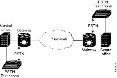
Restrictions and Usage Guidelines
Follow these restrictions and guidelines when you configure VXSM as a ToIP gateway:
•![]() VXSM Text Relay does not guarantee the support of third-party gateways.
VXSM Text Relay does not guarantee the support of third-party gateways.
•![]() Text Relay feature is supported only with the FMC template.
Text Relay feature is supported only with the FMC template.
•![]() VXSM as an IP-IP gateway supports Text Relay feature only for transcoding and transparent IP-IP voice calls. Text Relay is not be supported in fast-routing mode.
VXSM as an IP-IP gateway supports Text Relay feature only for transcoding and transparent IP-IP voice calls. Text Relay is not be supported in fast-routing mode.
VXSM as a ToIP Gateway
VXSM as a ToIP gateway supports two ToIP modes: Text Relay mode and TTY Upspeed mode. In Text Relay mode, the tones are translated into characters and then relayed over an IP network. In TTY Upspeed mode, the text is transported as tones over an IP network.
Text Relay Mode
VXSM configures Text Relay as an additional capability during a voice call. Text Relay does not require a call agent because there is no handshake procedure when TTY text phones are used. VXSM follows gateway controlled approach for Text Relay.
VXSM demodulates the text telephony signals detected from the TDM side and transmits the encoded characters as RTP (Real-time Transport Protocol) packets. The payload of a RTP packet consists of text encoded without any additional framing. The text characters are encoded according to the ITU-T recommendation T.140. These text characters are transported within the same RTP session as voice (audio/t140 payload format). While transporting encoded text data within the same audio stream, text packets are differentiated from audio packets by a payload type. The payload type value recognizes text packets from other packets transmitted within the audio stream.
VXSM allows users to configure various Text Relay parameters such as text payload type, redundancy payload type, redundancy level, and baudot rate on the gateway.
TTY Upspeed Mode
In TTY Upspeed mode, text is transported as tones over an IP network. During a voice call, when a TTY phone user types the character, the text phone generates the appropriate TTY signals. When VXSM detects these signals from the TDM side, it upspeeds the voice connection to TTY data mode. VXSM remains in the upspeed mode for the rest of the call. The detection of TTY tone and the upspeed is entirely controlled by the gateway. The gateway operates in non-NSE mode.
Note ![]() TTY Upspeed is supported only for VoIP calls.
TTY Upspeed is supported only for VoIP calls.
Configuring Text Relay
To configure Text Relay on VXSM, perform the following procedure:
Step 1 ![]() Create a Text Relay profile using the addtextrelayprof command.
Create a Text Relay profile using the addtextrelayprof command.
In the following example, a user creates a Text Relay profile with index 2:
CISCO.13.VXSM.a > addtextrelayprof 2 -textPayloadType 119 -textRedLevel 2
-textRedPayloadType 120 -modulation
Note ![]() Use the cnftextrelayprof command to configure the parameters of an existing Text Relay profile.
Use the cnftextrelayprof command to configure the parameters of an existing Text Relay profile.
Step 2 ![]() Create an event map pointing to the Text Relay profile created in Step 1.
Create an event map pointing to the Text Relay profile created in Step 1.
In the following example, a user creates an event map pointing to the Text Relay profile created in Step 1. Note that the handle type should be Text Relay and Mode 1.
CISCO.13.VXSM.a >cnfeventmapping -v18aTone 1 -htype 6 -prof 2-mode 1
Step 3 ![]() Associate the voice interfaces (vifs) with the configured event map.
Associate the voice interfaces (vifs) with the configured event map.
CISCO.13.VXSM.a > cnfvifeventmapping 1.1.1.1.1 0 1
Configuring TTY Uspeed
To configure TTY Upspeed on VXSM, perform the following procedure:
Step 1 ![]() Configure a TTY profile using the cnfttyprof command.
Configure a TTY profile using the cnfttyprof command.
In the following example, a user configures a TTY profile with index 1:
CISCO.13.VXSM.a > cnfttyprof 1 -ttycodec 14 -jmax 135 -jnom 70 -vad 2 -ppcontrol 1 -pp 4
Step 2 ![]() Configure an event map pointing to the TTY profile created in Step 1.
Configure an event map pointing to the TTY profile created in Step 1.
In the following example, a user configures an event map pointing to the TTY profile created in Step 1. Note that the handle type should be TTY Upspeed and Mode 1.
CISCO.13.VXSM.a >cnfeventmapping -v18aTone 1 -htype 4 -prof 1 -mode 1
Step 3 ![]() Associate the voice interfaces (vifs) with the configured event map.
Associate the voice interfaces (vifs) with the configured event map.
CISCO.13.VXSM.a > cnfvifeventmapping 1.1.1.1.1 0 1
Configuring RTP Multiplexing
Real-Time Transport Protocol (RTP) multiplexing enables VXSM to optimize the use of IP bandwidth between two gateways. VXSM achieves this by reducing the RTP header size, and multiplexing the payloads of different RTP sessions into a single UDP payload. In RTP multiplexing, the RTP sessions destined for a particular IP address are multiplexed into a single IP datagram.
Restrictions and Usage Guidelines
Follow these restrictions and guidelines when you configure the RTP multiplexing:
•![]() To enable In Service upgrade, you have to configure the gateway to OOS.
To enable In Service upgrade, you have to configure the gateway to OOS.
•![]() RTP Multiplexing is supported only for the TGW codec template. Feature support is available only for G729 and G.723 codec families. It is not supported for Data and Fax/T.38 calls.
RTP Multiplexing is supported only for the TGW codec template. Feature support is available only for G729 and G.723 codec families. It is not supported for Data and Fax/T.38 calls.
•![]() RTP Multiplexing is not applicable for SII and Calea calls. That is, these calls will not be multiplexed. However, MUX is supported on Calea images for normal voice calls.
RTP Multiplexing is not applicable for SII and Calea calls. That is, these calls will not be multiplexed. However, MUX is supported on Calea images for normal voice calls.
•![]() RTP Multiplexing is supported only on an OC3 VXSM card.
RTP Multiplexing is supported only on an OC3 VXSM card.
•![]() VXSM will not initiate RTP Multiplexing on endpoints which have moved to voice mode after Modem/ Fax transmission.
VXSM will not initiate RTP Multiplexing on endpoints which have moved to voice mode after Modem/ Fax transmission.
•![]() VXSM will stop RTP Multiplexing for calls which are IP forwarded.
VXSM will stop RTP Multiplexing for calls which are IP forwarded.
•![]() RTP Multiplexing is not supported for H.248 protocol in Release 5.6.00.
RTP Multiplexing is not supported for H.248 protocol in Release 5.6.00.
•![]() VXSM initiates RTP Multiplexing only if there are at least three calls having the same source IP and destination IP pair.
VXSM initiates RTP Multiplexing only if there are at least three calls having the same source IP and destination IP pair.
•![]() VXSM does not support multiplexing for intra-card calls even if IPs are different.
VXSM does not support multiplexing for intra-card calls even if IPs are different.
•![]() There is a DS0 density impact when RTP Multiplexing is enabled. The total DS0 capacity impact would be 384.
There is a DS0 density impact when RTP Multiplexing is enabled. The total DS0 capacity impact would be 384.
•![]() While VXSM is used for AAL2 trunking, if you want to run the RTP Multiplexing commands, you have to first delete all the CIDs.
While VXSM is used for AAL2 trunking, if you want to run the RTP Multiplexing commands, you have to first delete all the CIDs.
•![]() If online or offline diagnostics is enabled on a VXSM card, you have to disable it before you run the RTP Multiplexing commands.
If online or offline diagnostics is enabled on a VXSM card, you have to disable it before you run the RTP Multiplexing commands.
•![]() You have to delete SS7, LAPD, and CAS signaling links before you enable RTP Multiplexing.
You have to delete SS7, LAPD, and CAS signaling links before you enable RTP Multiplexing.
Enabling RTP Multiplexing
Make sure that VXSM is not handling any traffic when you configure RTP multiplexing. To configure RTP multiplexing, perform the following procedure:
Step 1 ![]() Bring the gateway to OOS state.
Bring the gateway to OOS state.
In xGCP:
In the following example, a user brings a gateway with index number 1 to OOS state:
CISCO.13.VXSM.a > cnfgwoos 1
In H.248:
In the following example, a user gracefully shuts down the gateway link:
CISCO.13.VXSM.a > cnfh248oos 1 2
Step 2 ![]() Run the cnfrtpmux command to enable RTP multiplexing.
Run the cnfrtpmux command to enable RTP multiplexing.
In the following example, a user sets the RTP multiplexing mode to 1 to enable RTP multiplexing:
CISCO.13.VXSM.a > cnfrtpmux 1
Step 3 ![]() Run the dsprtpmux command to verify the settings.
Run the dsprtpmux command to verify the settings.
In the following example, a user displays the mode of the RTP multiplexing:
CISCO.13.VXSM.a > dsprtpmux
======================================================
Gateway Level RTP Multiplexing
======================================================
RTP Mux : True
Configuring DSP Tone Parameters
From Release 5.6.21 onwards, you can configure Digital Signal Processor (DSP) tone parameters such as hangover and Signal-to-Noise Ratio (SNR).
Restrictions and Usage Guidelines
Follow these restrictions and guidelines when you configure DSP tone parameters on VXSM:
•![]() This feature is supported on all codec templates for the H248 and MGCP protocol.
This feature is supported on all codec templates for the H248 and MGCP protocol.
•![]() This feature supports all card types such as T1, E1, OC3, and so on.
This feature supports all card types such as T1, E1, OC3, and so on.
•![]() The default parameter value of ha is one and the value of tof is 0x700.
The default parameter value of ha is one and the value of tof is 0x700.
Configuring DSP Tone Parameters
To configure DSP tone parameters, perform the following procedure:
Step 1 ![]() Use the cnfgwparams -tone command to configure the DSP tone parameters. The command format is as follows:
Use the cnfgwparams -tone command to configure the DSP tone parameters. The command format is as follows:
cnfgwparams -tone [ha <Hangover>][tof <SNR>]
Table 5-8 describes the parameter value for the cnfgwparams -tone command.
ha |
Specifies the following hangover values: 1—represents 0 2—represents 300 |
tof |
Specifies the following SNR values: 1—represents 0x700 2—represents 0x0 |
Step 2 ![]() Use the dspgwparams -tone command to display the DSP tone parameters.
Use the dspgwparams -tone command to display the DSP tone parameters.
In the following example, a user displays the DSP tone parameters:
DEChassis.14.VXSM.a > dspgwparams -tone
================================================================================
Display Tone Parameters
================================================================================
Hangover Signal_to_Noise_Ratio
================================================================================
Enable Enable
Configuring Agere Parameters
From Release 5.6.21 onwards, you can configure the agere parameters to enable VXSM to switchover automatically during an agere queue failure.
Restrictions and Usage Guidelines
Follow these restrictions and guidelines when you configure the agere parameters on VXSM:
•![]() This feature is supported on all codec templates for the H248 and MGCP protocol.
This feature is supported on all codec templates for the H248 and MGCP protocol.
•![]() This feature supports all card types such as T1, E1, OC3, and so on.
This feature supports all card types such as T1, E1, OC3, and so on.
•![]() The default parameter value of swOnAgrStuck is disabled.
The default parameter value of swOnAgrStuck is disabled.
Configuring Agere Parameters
To configure agere parameters, perform the following procedure:
Step 1 ![]() Use the cnfgwparams -agere command to enable VXSM to switchover automatically during an agere queue failure. The command format is as follows:
Use the cnfgwparams -agere command to enable VXSM to switchover automatically during an agere queue failure. The command format is as follows:
cnfgwparams -agere [swOnAgrStuck <AgereSwFlag>]
Table 5-9 describes the parameter value for the cnfgwparams -agere command.
AgereSwFlag |
Specifies the following values: 1—Disable 2—Enable |
Step 2 ![]() Use the dspgwparams -agere command to display the value of AgereSwFlag used for automated switchover during agere queue failure.
Use the dspgwparams -agere command to display the value of AgereSwFlag used for automated switchover during agere queue failure.
In the following example, a user displays the value of the agere parameter:
DEChassis.14.VXSM.a > dspgwparams -agere
================================================================================
Display Agere Parameters
================================================================================
Agere Parameters
================================================================================
Disable (Default)
Configuring T.38 Attribute
From Release 5.6.21 onwards, you can configure the T.38 attributes that are sent in response to the Session Description Protocol (SDP).
Restrictions and Usage Guidelines
Follow these restrictions and guidelines when you configure the T.38 attributes:
•![]() This feature is supported on all codec templates for the H248 protocol.
This feature is supported on all codec templates for the H248 protocol.
•![]() This feature supports all card types such as T1, E1, OC3, and so on.
This feature supports all card types such as T1, E1, OC3, and so on.
•![]() The default parameter value of -t38Attr is disabled.
The default parameter value of -t38Attr is disabled.
Configuring T.38 Attributes
Step 1 ![]() Use the cnfgwparams -t38params command to configure the T.38 attributes that are sent in response to the SDP. The command format is as follows:
Use the cnfgwparams -t38params command to configure the T.38 attributes that are sent in response to the SDP. The command format is as follows:
cnfgwparams -t38params [-t38Attr <T.38 Attribute>]
Table 5-9 describes the parameter value for the cnfgwparams -t38params command.
T.38 Attribute |
Specifies the following values: 1—Disable 2—Enable |
Step 2 ![]() Use the dspgwparams -t38params command to display the T.38 attribute values that can be sent in the SDP.
Use the dspgwparams -t38params command to display the T.38 attribute values that can be sent in the SDP.
In the following example, a user displays the T.38 attribute values:
DEChassis.14.VXSM.a > dspgwparams -t38params
================================================================================
Display T38 Parameters
================================================================================
T38 Attribute Parameters
================================================================================
Disable (Default)
 Feedback