Setup and Initial Configuration
Available Languages
Table Of Contents
SES PNNI Controller Setup and Initial Configuration
SES PNNI Controller Interfaces
Attach the Interfaces at the BPX and the PNNI Controller
Perform Initial Configuration Tasks at the PNNI Controller
Connect a Terminal to the PNNI Controller and Start the CLI
PNNI Controller Command Line Interface Overview
Check PXM Front Card/Back Card and BXM
Update Backup Boot File and Runtime Controller Image
Prepare to Install the Backup Boot File
Configure SES PNNI Controller Shelf Parameters
Bring Up the SES PNNI Controller
SES PNNI Controller Setup and Initial Configuration
This chapter assumes you have rack-mounted the PNNI Controller and the BPX switch, and have powered up the units as described in the Cisco Service Expansion Shelf (SES) Hardware Installation Guide. If so, you are now ready to perform the initial setup task sequence shown in Figure 8-1.
Figure 8-1
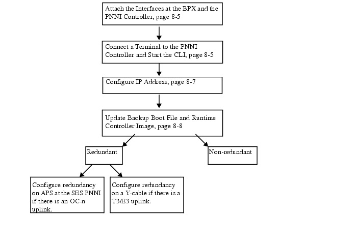
Initial Setup Tasks for PNNI Controller
After completing the initial setup, you will be ready to bring up the system.
SES PNNI Controller Interfaces
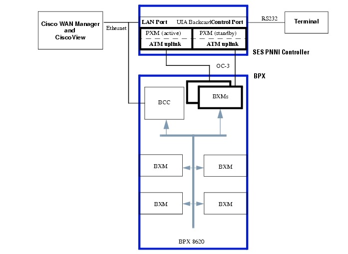
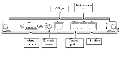
The SES PNNI controller interfaces (Figure 8-2) are located on the PXM UIA backcard (Figure 8-3) of the SES PNNI node. Control interfaces associated with PNNI configuration are as follows:
•
PXM Control Port
•
•
•
The remaining ports on the PXM-UIA backcard—T1 clock input, E1 clock input, and external alarm output—are typically not used during the SES PNNI controller application. These ports support external audio or visual alarms and external clock sources.
Figure 8-2 BPX and SES PNNI Controller Interfaces
PXM Control Port
The control port (sometimes referred to as the Console Port) provides an RS232 interface for connecting an ASCII terminal to the shelf, and for running the PNNI Controller CLI. This interfaces provides an RJ45 connector with the following configuration:
•
•
•
•
•
•
The control port provides:
•
•

Note
Altenatively, you can use DNS, if applicable.
Note
PXM LAN Port
The LAN port provides an Ethernet interface. It uses an RJ45 connector, 10BaseT, and supports 802.3 Ethernet. Through the Ethernet Port, you can use a workstation running a Cisco network management application such as the Cisco WAN Manager (formerly known as StrataView Plus) or CiscoView applications. At least one SES PNNI node is typically collocated with a NMS workstation, and connected to the same Ethernet segment. That BPX often serves as the gateway for the IP relay (network IP) inband communication with the other SES PNNI nodes.
The CLI is accessed through the PXM LAN port.
PXM Maintenance Port
The maintenance port provides modem access to the SES PNNI controller. It has an RJ45 connector with the following configuration:
•
•
•
•
•
•
Through the maintenance port (which is sometimes referred to as the Modem Port), you can connect either a single workstation running an IP-based application, or a terminal server that supports multiple workstations. The workstation to be used must support either SLIP or PPP. Typically, use of this port includes a modem because the switch resides at a remote location. The typical applications are software and firmware download or tasks that require low-level access.
Both the maintenance port and LAN port support IP-based applications. You can access these ports to run Telnet, TFTP, or SNMP.
•
•
•
Figure 8-3 User Interface (PXM UIA) Backcard
Attach the Interfaces at the BPX and the PNNI Controller
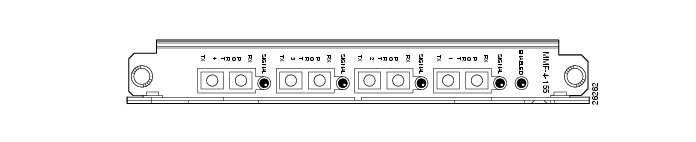
The PNNI Controller OC-3 or T3/E3 ATM uplink backcard (Figure 8-4) must be connected to the BPX switch at the BXM cards (Figure 8-2). Both the active and standby PXMs must be connected to the BPX.
The BPX BXM card may also need to be configured for SONET Automatic Protection Switching (APS), as described in "Configure SES PNNI Redundancy" section on page 8-15.
Figure 8-4 PXM OC-3 Backcard
Perform Initial Configuration Tasks at the PNNI Controller
The initial configuration of the SES PNNI controller typically consists of the following task sequence:
1.
2.
3.
Connect a Terminal to the PNNI Controller and Start the CLI
Use the steps in this section to connect the PNNI Controller terminal to be used to access the PNNI Controller CLI.
Connect your terminal to the RJ45 control port on the PXM-UIA backcard of the SES. Make sure your terminal communication parameters are set to match the control port's, using the following settings:
•
•
•
•
•
Step 4
Note

Tips
Tips
PNNI Controller Command Line Interface Overview
The PNNI Controller command line interface (CLI) provides access to the PNNI Controller and is typically used during initial installation, troubleshooting, or any situation where low-level control is useful.
The PNNI Controller command line prompt (Figure 8-5) displays the name of the SES PNNI Controller, the shelf number, the slot number and type for the current card, and the current status of the currently displayed PXM.
Figure 8-5 Command Prompt Components

The example in Figure 8-5 shows that an active PXM card is resident in slot 1 of the node known as excel.
Note
The command notation and argument parameters comply with the following, standard programming conventions
•
•
•
•
•
You must type all command arguments, then press the Return key or Enter key. If you need to view the syntax and arguments for a command, type the command without arguments. The prompt will return the full range of parameters for the specified command.
Bring Up PXM1 Card
Check PXM Hardware Jumper J1
Before boot up a PXM1, make sure Jumper J1 is removed. Jumper J1 is used only when PXM1 is hung. Putting Jumper J1 in will force the PXM1 boot with backup boot image. From there, a good runtime image then can be loaded. The PXM1 will boot up with run time image only when Jumper J1 is removed.
Check PXM Front Card/Back Card and BXM
Check to make sure the following components have identical port speed (for example, DS3/T3 vs. OC-3. PXM):
•
•
•
For an OC-3 uplink, make sure the PXM backcard and uplink BXM port are using same type of fiber, (for example, SMF vs. MMF). For Single Mode Fiber (SMF) used for uplink, the transmission range on both PXM backcard and BXM uplink port must be identical. Other wise, you need an attenuator to match the transmission power. Any mismatching on transmission speed, fiber type, or transmission range will prevent PXM from coming up properly. Check the hardware thoroughly before you bring up the software.
Boot Up PXM1
A new PXM card from the factory must be plugged into an SES shelf on slot 1 or 2. No other card should be plugged into the SES.
Step 1
Step 2
Step 3
Step 4
The card comes up as active.
Use the steps in the following two sections to load runtime firmware onto a PXM that only has a boot loader.
Configure IP Address
Configure the IP address before loading runtime firmware onto a PXM.
Tips
Step 1
Step 2
Step 3
If the workstation from which you will be downloading firmware is on a different subnet from the PXM, configure the IP address of the gateway device that connects the subnets.
>'.' = clear field; '-' = go to previous field; ^D = quitboot device : lnPciprocessor number : 0host name :file name :inet on Ethernet (e) : 172.29.37.41:ffffff00inet on backplane (b):host inet (h) :gateway inet (g) : 172.29.37.1user (u) :ftp password (pw) (blank = use rsh):superuserflags (f) : 0x0target name (tn) :startup script (s) :other (o) :The PXM now has an IP address.
Step 4
Step 5
Step 6
telnet PXM1 inet IP
Update Backup Boot File and Runtime Controller Image
When a PXM1 card is booted up, a user may get one of the following prompts:
•
•
•
spirit.1.PXM.a>represents the CLI prompt.)This means the system is booted up with run time image (using cisco as default login and password).The following sections are associated with updating the backup boot file and runtime controller image:
•
•
Prepare to Install the Backup Boot File
The following items must be in place prior to attempting installation of the SES PNNI platform software.
•
•
•
•
pxm1_001.000.001.000_bt.fw
•
pxm1_001.000.010.000_ses.fw
The compatible backup boot image and run time image for different SES release is shown in Table 8-1.
Note
Check the PXM for the existing Backup Boot Image and Runtime Image:
•
pxm1bkup> cd "C:/FW"
pxm1bkup> ll
•
spirit.1.PXM.a> dspversion
If you do not have the latest _bt.fw and _ses.fw in C:/FW directory, you do not have the latest backup boot image or run time image in the PXM. Update your system image with the following procedures. Otherwise, skip to the "Configure SES PNNI Controller Shelf Parameters" section.
pxm1_001.000.010.000_ses.fw
run time firmware image
set rev 1 1.0(10) 1.0(10) 1
pxm1_001.000.001.000_bt.fw
boot image
not applicable
1 The setrev command will be incrementally updated according to subsequent releases of the SES. For example, the setrev command for the next release will be setrev1.0(11).
Install the Backup Boot
Follow these steps to install the backup boot:
Step 1
For example:
$ftp162.29.38.101
The FTP prompt appears.
Login to the system with username and password.
ftp> cd "FW"
ftp> bin
ftp> put pxm1_001.000.001.000_bt.fw pxm1_001.000.001.000_bt.fw
Note
Step 2
pxm1bkup>sysFlashBootBurn("C:/FW/pxm1_001.000.001.000_bt.fw")
The system will look for the file pxm1_001.000.001.000_bt.fw in C:/FW directory, and burn it onto the flash.
Note
This new back up boot image should be brought up by rebooting the card.
The system will then come up in backup boot.
Install the Runtime Image
Follow these steps to install the runtime image:
Step 1
For example:
$ftp 162.29.38.101
The FTP prompt appears.
Login to the system with username and password.
Step 2
cd "FW"
Step 3
bin
Step 4
put pxm1_001.000.010.000_ses.fw pxm1_001.000.010.000_ses.fw
Step 5
quit
Use the control terminal for Step 6 through Step 7.
Step 6
Unknown.1.PXM.a> cd c:/FW
Unknown.1.PXM.a> ll
Step 7
1. If you are in the CLI Prompt:
setrev <slot> <primary version> <secondary version>
For example, setrev 1 1.0(10) 1.0(10), then the system will reboot.
2. If you are in the backup boot prompt:
sysVersionSet "version"
version
The version number of the firmware. The name of a PXM firmware file has the format pxm1_version_ses.fw.
For example, in pxm1_001.000.010.000_ses.fw, the version will be 001.000.010.000.
reboot
A login prompt appears on the console. The system is now in the same state as one that has a PXM shipped with a runtime firmware image.
Configure SES PNNI Controller Shelf Parameters
Use the PNNI Controller terminal to perform the following procedure.
Step 1
login: username
password: user password
Step 2
•
•
Because the PXM has not been configured with a name, the prompt appears similar to the following example:
UNKNOWN.1.PXM.a>The PNNI Controller prompt contains the node name, shelf number, slot number, and activity status of the current PXM ().
Step 3
Unknown.1.PXM.a> dspcds
Note
Step 4
Unknown.1.PXM.a> dspipif
Step 5
Unknown.1.PXM.a> ipifconfig <interface> <IP_Addr> [netmask Mask] <broadcast broad_addr>
Note
Step 6
Unknown.1.PXM.a> cnfname <node name>
node name
A case-sensitive character string of up to eight characters. The configured node name will be identified in the CLI command prompt.
Unknown.1.PXM.a> cnfname <nodename>
nodename.1 PXM a>
Step 7
Step 8
Use the cnftime command to configure the time of the system. Use either the cnftmzn or the cnftmzngmt command to configure a time zone for the node:cnftime <hh:mm:ss>. For example, cnftime 11:20:30
If the node resides within the timezones of the Western Hemisphere, use the cnftmzn command:
cisco22.1.PXM.a> cnftmzn <timezone>
timezone
Greenwitch Mean Time
Eastern Standard Time
Central Standard Time
Mountain Standard Time
Pacific Standard Time
Value to indicate timezone to be used on the node.
GMT
EST
CST
MST
PST
If the node resides outside the timezones of the Western Hemisphere, use the cnftmzngmt command.
cisco22.1.PXM.a> cnftmzngmt <timeoffsetGMT>
timeoffsetGMT
Value to indicate GMT offset hours to be used on the node, in the range -12 through +12.
Note
Step 9
cnfstatsmgr <IP_Addr>
If the node has a redundant PXM, it automatically receives the same IP addresses and configuration as the primary PXM. With the IP addresses in place, you can configure the broadband (ATM uplink) interface through the CiscoView application or the CLI.
Bring Up the SES PNNI Controller
Use the procedure in this section to add the PNNI Controller at the BPX.
At the BPX CLI, perform the following steps:
Step 1
uptrk slot.port
Slot is the uplink BXM slot number in BPX, and port is the port number of the BXM used for uplink.
Step 2
cnfvsiif slot.port 3
Step 3
cnfrsrc slot.port
Recommended values for resource configuration of a typical uplink are:
Maximum PVC LCNS = 0
Maximum PVC Bandwidth =0
Partition = 1
Partition State = Enabled
Minimum VSI LCNS =1000
Maximum VSI LCNS =3000
Start VSI VPI =4
End VSI VPI =4095
Minimum VSI Bandwidth =100,000
Maximum VSI Bandwidth =300,000
VSI ILMI Config = 0 (disabled)
Step 4
addshelf slot.port x
Step 5
addctrlr slot.port
Cntl_Id = 2 for PNNI Controller
Part_Id = 1 for partition #1
Control_VC_VPI = 0
Control_VC_VCI = 40 to reserve VCI Range 40 to 54 for control VCs.
The VSI protocol will start operating and the VSI master in the PNNI controller will establish communication with the VSI slaves running in the BXM cards at the BPX.
Initial configuration is not required from the PNNI controller. The default node name and address will be used in the messages between the BPX and the PNNI Controller.
When the Uplink is up, dsplmilink on SES should display the current alarm status as "clear", and dspcds on BPX should show all the active cards in the shelf including uplink.
Configure SES PNNI Redundancy
A redundant card comprises two sets of front cards and back cards. One set of front and back cards is known as the active pair and the other set is known as the standby pair. All the work is done by the active pair of cards and the standby pair acts as a backup If the active front card fails, the standby front and back card take over. If the active back card fails, manual intervention is needed. because the standby back card won't take over automatically. There are three types of redundant configurations:
1.
2.
3.
OC-3 Y-cable redundancy
Required Hardware
•
•
•
Take one Y-cable. Plug one SC-connector to the RX port of one back card and plug the other
SC connector to the RX port of the other back card. Plug the SC connectors of the other Y-cable to the TX ports of the back cardsThe other end has to be plugged to the BXM. So the RX cable from the SES goes to the TX port of the BXM and the TX cable of the SES goes to the RX port of the BXM.
User Command (CLI) on the SES
None
Commands on the BPX Side
* uptrk a.b (a.b is the port connected to the SES)
* cnfrsrc a.b params
* addshelf a.b x (for AAL 5)
* addctrlr a.b params
Note
The uplink between the BPX and the SES is working if:
•
•
TRK Current Alarm Status Other End
1.1 CLEAR orpbpx/9.5
DS-3/E3 Y cable redundancy
Required Hardware
•
•
•
Take one Y - cable. Plug one SMB connector to the RX port of one back card and plug the other SMB connector to the RX port of the other back card. Plug the SMB connectors of the other Y-cable to the TX ports of the back cards. The other end has to be plugged to the BXM. So the RX cable from the SES goes to the TX port of the BXM and the TX cable of the SES goes to the RX port of the BXM.
User Command (CLI) on the SES
None
Commands on the BPX Side
•
•
•
•
Note
The BPX and the SES is working if:
•
•
TRK Current Alarm Status Other End
1.1 CLEAR orpbpx1/4.2APS Redundancy
SES supports dual back-card APS 1+1 mode redundancy. "Dual back-card" means that the protection line must be on a back-card different from the working line's back-card. APS is supported only for line 1 and only for type OC-3 of the uplink.
It is possible to use the uplink (between the BPX and SES) both without and with APS. If APS is added (enabled), it provides line- and card-level redundancy for the uplink. Therefore, if a single line or back-card fails, the uplink will still carry traffic over the other line.
The APS line that was active before a front-card failure or front-card switchover continues to be the active APS line after the transitions (if any) of the front-cards.
Required hardware
•
•
Note
User commands (CLI) on the SES
•
•
•
•
•
•
•
•
For more details on the syntax and usage of these commands, please refer to Appendix C of this guide.
Note
Here is a nominal sequence of commands that a user would typically use to set up APS on the SES:
a.
b.
c.
d.
e.
f.
For the purpose of this section, consider that the commands are being run on an SES shelf that has been named "PSbench" (this is done using the cnfname command).
Step 1
This command adds (enables) APS in 1+1 dual back-card mode on line 1,with line 1 on slot 1 as the working line and line 1 on slot 2 as the protection line.
Sample screen output:
PSbench.1.1.PXM.a >addapsln1 1 1 2 2
PSbench.1.1.PXM.a >Step 2
This command displays the current APS configuration.
Sample screen output:
PSbench.1.PXM.a > dspapslnSlotLine Type Act W_LINE P_LINE APS_ST CDType Dir Revt LastUsrSwReq------------------------------------------------------------------------1.1&2.1 1+1_2 1.1 OK OK OK OC-3 UNI NRV NO_REQUESTStep 3
This command displays the values of the various APS parameters.
Sample screen output:
APSbench.1.PXM.a > dspapscfgSlotLine Type SFBER SDBER WTR Dir Revert K1K2-----------------------------------------------------1.1&2.1 1+1_2 3 5 1 UNI NRV ENAStep 4
This command configures APS for bi-directional revertive mode with K1/K2 bytes enabled, with the following values for:
•
•
•
Sample screen output:
PSbench.1.1.PXM.a >cnfapsln1 3 9 2 1 2 1
PSbench.1.1.PXM.a >Step 5
This command displays the current APS configuration.
Sample screen output:
APSbench.1.PXM.a > dspapslnSlotLine Type Act W_LINE P_LINE APS_ST CDType Dir Revt LastUsrSwReq------------------------------------------------------------------------1.1&2.1 1+1_2 1.1 OK OK OK OC-3 BI RVE NO_REQUESTStep 6
This command displays the values of the various APS parameters.
Sample screen output:
APSbench.1.PXM.a > dspapscfgSlotLine Type SFBER SDBER WTR Dir Revert K1K2-----------------------------------------------------1.1&2.1 1+1_2 3 9 1 BI RVE ENA
 Feedback
Contact Cisco
- Open a Support Case

- (Requires a Cisco Service Contract)
This Document Applies to These Products
- Collaboration Endpoints - Retired Products
- Conferencing - Retired Products
- Contact Center - Retired Products
- Optical Networking - Retired Products
- Routers - Retired Products
- Security - Retired Products
- Servers - Unified Computing (UCS) Retired Products
- Storage Networking Retired Products
- Switches - Retired Products
- Video - Retired Products
- Wireless - Retired Products