Network Management
Available Languages
Table Of Contents
Installing and Configuring Cisco WAN Manager
Disk Partitioning Requirements
Modifying the network.conf File for PNNI Networks
Configuring PNNI Topology Discovery
Configuring the SES PNNI Controllers
Cisco WAN Manager SES PNNI Features
Making Selections and Displaying Menus
Device-Specific Buttons within Configure Menu
Integrating New Device Information
Device Support Utility Features
Using the Device Support Utility
Testing Basic Connectivity and Setup
2. Open a Telnet session to the device:
3. Verify the CiscoView preferences
Network Management
This chapter describes the network management tools you can use with Cisco SES PNNI nodes and PNNI networks, which are as follows:
•
Cisco WAN Manager SES PNNI Features
Minimum System Requirements
The following hardware and software components make up the Cisco WAN Manager Network Management workstation:
Hardware
This section lists the hardware requirements for a Cisco WAN Manager Network Management workstation. Table 11-1 lists the minimum workstation requirements. Using a workstation that meets these requirements will ensure adequate performance.
Table 11-1 Minimum CWM 10.2 Workstation Requirements
Workstation
Sun Ultra 10
Memory
512 MB
CPU Speed
440 MHz
Hard Disk Drive
9.1 GB
Graphics Card
24-bit
Monitor
19 inch
Three types of machines are supported for WAN Manager 10.2 as standard platforms. They are low-end, mid-range, and high-end platforms. Table 11-2 describes the configuration for each platform.
Table 11-2 Sun Platform Requirements

Note
The selection of a proper CWM platform depends on a number of factors, such as, the number of CWM desktops, the number of managed connections, and the number of statistics collected and stored. Table 11-2 lists recommended CWM platforms based on the size of network.
The following are additional notes for CWM platform requirements:
•
•
•
•
•
•
•
Software
This section lists the required software to install on the Cisco WAN Manager Network Management workstation to manage the SES PNNI nodes and PNNI networks.
•
•
•
•
•
•
•
HP OpenView 6.1 is not bundled with CWM CDs. You must order HP OpenView separately.
For HP OpenView installation requirements and procedures, please refer to the "HP OpenView Network Node Manager Products, Installation Guide" (part # J1136-90000 from HP).
•
•
Installing and Configuring Cisco WAN Manager
Refer to the appropriate chapters in the Cisco WAN Manager Installation Guide for Solaris, Cisco WAN Manager 10.2 for general workstation setup (including disk partitioning) and installation procedures.
Disk Partitioning Requirements
A change in the installation procedure requires that you use the following disk partitioning requirements instead of those found in the CWM 10.2 Installation Guide for Solaris (Doc-7810308=).
Sufficient disk space and proper disk partitioning are essential to achieving the best performance from CWM and your network management workstation.
Note
Use the following commands to gather some of the required information. The dmesg command provides information about the workstation type, amount of memory and CPU speed.
dmesg | more
The format command enables you to determine information about the disk drives on your workstation. Select a disk from the list of those available, and use the verify command to determine the current partitioning of each disk.
Partitioning One 9-GB Disk
This section describes how to partition a CWM workstation's single 9-GB disk drive. The following procedure ensures that all but the final partition will be at a set size.
Note
Table 11-3
Partitioning a Single 9-GB Disk
Note
Partitioning Two 9-GB Disks
This section describes how to partition a CWM workstation that has two 9-GB disk drives. When you install Solaris, partition the first disk drive as shown in Table 11-4. Do not partition the second disk. The second disk is automatically partitioned during the CWM software installation.
Table 11-4
Partitioning the First 9-GB Disk
Note
Related Documentation
The following technical documents comprise the CWM 10.2 documentation set:
•
•
•
•
•
•
•
Modifying the network.conf File for PNNI Networks
For SES PNNI networks using in-band management, provide the following information for your network:
NETWORK:Network2GATEWAYS:sj234567DISCOVERY PROTOCOL:PNNI
Note
Configuring PNNI Topology Discovery
Use the Topology Configurator to provide information required to communicate with the nodes. Also use the configurator to specify Network IP.
Note
Configuring the SES PNNI Controllers
To configure a PXM-SES card, telnet to the card and execute the following shellConn commands:
pxm> shmsimulateresetReason 0pxm> deltree "D:DB2"
Note
pxm> addpnport 9.1 assumes a BXM in slot 9pxm> cnfpnportsig 9.1 -nniver pnni10Cisco WAN Manager SES PNNI Features
Cisco WAN Manager (CWM) provides the following features for the Cisco SES PNNI controller:
•
–
•
•
•
•
•
•
SPVC Overview
Table 11-5 lists the types of SPVCs supported by the SES PNNI controller using CWM 10.2.
Table 11-5 Supported SPVC Connections
TypeBXM
BXM
ATM SPVC
Routing nodes on BPX with feeder node on SES
WAN CiscoView 3.2
The Cisco SES PNNI controller is managed through WAN CiscoView 3.2. WAN CiscoView 3.2 requires Release 5.1 of the CiscoView Engine, which is included on the CWM 10.2 CD.
CiscoView Release 5.1 has been migrated from X/MOTIF to a JAVA based application. WAN CiscoView 3.2 supports line, port and resource partition configuration and real-time counters on Cisco SES PNNI controllers.
The look and feel of CiscoView 5.1 is slightly different from CiscoView 4.2, but most dialog screens will be familiar to experienced CiscoView users. Rear view selection (normally done by selecting the outer part of the device with the right mouse button) is not available for the Cisco SES PNNI controller.
Installing CiscoView
During the CWM 10.2 installation process, CiscoView 5.1 and BPX-SES device packages are installed for you. This eliminates the need to incrementally select device packages to install.
Accessing CiscoView
Accessing CiscoView is a simple task. From the CWM 10.2 Topology Map, a device can be selected for management by CiscoView.
Navigating in CiscoView
When you start CiscoView, the CiscoView main window opens. The following components comprise the CiscoView main window:
•
•
•
•
Select Device Drop-Down List Box
Use the Select Device drop-down list box to select and display a device. Either enter a device name or IP address, or select from the recently displayed devices listed.
Device names and SNMP read and write community strings are preserved when you open new CiscoView sessions.
Device Commands Buttons
Use the Device Commands buttons to activate device commands unique to the displayed device.
The Device Command buttons are described in the online help for each device package.
Main Menu Buttons
Use the Main Menu buttons to perform various CiscoView tasks.
Graphical Device Display Window
Use the Graphical Device Display window to view a graphical display of the device's back or front panel once you select a device. The display shows all device components color-coded according to their current status and refreshed according to your polling frequency. If a hot swap is detected, the device is rediscovered and the display redrawn at the next poll.
Status Bar and Buttons
Use the Status Bar and buttons to display the result of device polling, selections, and so on.
Main Menu Buttons
Telnet
Launches a Telnet command-line session to the managed device.
CCO
Launches a separate browser containing the Cisco Connection Online (CCO) web page.
This feature is not supported in WAN CiscoView 3.2.
Cisco Support
Opens the TAC Mailer dialog box for sending reports to the Cisco Technical Assistance Center (TAC) group. You can describe the problem using the available options and the comment field. When you click Send, your descriptions and information about the runtime device package and operating environment are sent to the specified mail recipients.
This feature is not supported in WAN CiscoView 3.2.
Preferences
Opens the Preferences dialog box where you can specify SNMP and community string. The preferences settings are preserved for all new CiscoView 5.1 sessions.
About
Displays the following:
CiscoView release version and copyrights
Active device package, if applicable
All installed device package information
Help
Opens CiscoView 5.1 help if no device is selected.
Opens context help if a device or component is selected.
This feature is not supported in WAN CiscoView 3.2.
Status Bar and Buttons
Status Bar
Displays the progress and result of device polling, selections, and so on.
System Info Button
Displays system information (name, description, location, contact, and up-time) for a displayed device.
Print Button
Prints the current graphical display.
Color Legend Button
Describes the significance of the colors on the graphical display. Color schemes are:
•
•
•
•
•
•
Making Selections and Displaying Menus
When you select a device in CiscoView, a graphical representation of the device is displayed. You can view front device panel and select different components and menu options to configure and monitor status for these devices.
Popup Menu Options
Configure
Configures device categories, such as Node Management, NNI, and so on.
Monitor
Displays a set of dynamic charts for selected device categories.
Front and Rear
Displays either the front or back device panel. The BPX-SES has only a front panel view.
Resize
Reduces the graphical display down to 90%, 80%, 70%, 60%, or 50%. You can resize it back up to 100%.
Refresh
Triggers component polling and display update.
System Info
Displays system MIB information (name, description, location, contact, and up-time) for a device.
Using CiscoView
Once you have installed CiscoView and learned to navigate within it, you can perform various tasks.
Starting CiscoView
Depending on your platform, you can start CiscoView:
•
•
Selecting a Device
Select a device to view its graphical representation to configure and monitor it. The device names and SNMP read and write community strings are preserved when you open new CiscoView sessions.
Setting Preferences
Use the Set Preferences option to change certain options within CiscoView.
Selecting a Component
Select a component on the graphical device display to configure and monitor it.
Configuring Your Device
Use the Configure menu to configure multiple categories of information, for example, Interface, Management, Physical, and ARP Table, simultaneously.
Different categories of information can be displayed for each device, card, and port. To see the categories of information that can be displayed for each component type, look at the Category pop up menu from the Configuration window.
Monitoring Your Device
Use the Monitor menu to monitor multiple categories of information, for example, Ethernet collisions, Management, Physical, and ARP Table, simultaneously. The Monitoring dialog is non-modal and resizeable.
Preference Setting Options
Setting Community Strings
Use the Preferences Community tab to delete the read and write community strings for the device currently being managed. This lets you enter the read and write community strings for a device after you display the device. If you want to make changes to a device or port setting, but did not specify community string when you first opened the device display, you can enter the community string without exiting and reopening the device window.
If a host's community strings are not already defined within CiscoView, you can add them with the CiscoView Community Strings dialog. Otherwise, CiscoView allows you to enter the correct community strings when you try to access the host.
If you do not enter a host's community strings when accessing the host, CiscoView uses the default read and write community strings of "public" and "private".
Setting SNMP Preferences
Use the Preferences SNMP tab to set polling frequency, SNMP timeout and retries, and default read and write community strings. The recommended values for preferences are:
•
•
•
•
Use the Default Read and Write Community fields to define the community strings that CiscoView automatically uses for device when you do not specify the device's current community strings.
Device-Specific Buttons within Configure Menu
OK
Writes modification of all categories to managed device then closes the dialog box
Apply
Writes modification of the current category to managed device, leaving the dialog box open
Cancel
Aborts changes and closes the catalog list
Prints the current category
Help
Launches device-specific help
Create
Launches a table row creation dialog box
Delete
Deletes a selected row from the table
Integrating New Device Information
Use the Device Support Utility to integrate new Cisco device information asynchronously with the CiscoView engine, uninstall device packages, install new device packages, or upgrade existing installed packages.
The Device Support Utility operates in one of two modes: Interactive mode or Command Line mode. The functionality of both modes is similar; the only difference between the two is that Interactive mode provides a Graphical User Interface (GUI). Each mode allows the user to display a list of currently installed device packages and their versions, uninstall one or more packages, and automate device package installations and upgrades.
Device Support Utility Features
Use the Device Support Utility to:
•
•
•
Using the Device Support Utility
Starting the Device Support Utility
From a UNIX platform, you can start the Device Support Utility by running the script "xdsu" from the ~svplus/wancv/bin directory.
Installing Device Packages
In Interactive mode, the Install Device Packages dialog box installs new device packages or upgrades existing packages. The Device Support Utility will not allow you to select a package whose superseding version has already been installed in the package repository.
Uninstalling Device Packages
In Interactive mode, the Device Support Utility dialog box shows a list of the device packages that are already installed. It also acts as a launch point for uninstalling device packages.
Testing Basic Connectivity and Setup
Troubleshooting
The following information describes how to test the basic connectivity and setup for CiscoView. Perform these tasks first when you have a CiscoView-related problem.
1. Test the IP connectivity:
From the UNIX workstation, try to ping the router's IP address. If the ping is unsuccessful, make sure that IP routing is properly enabled and is functioning. Use "ping -s" to check for slow IP response. Ping the device by its Network IP as well as by its LAN IP address.
If you can ping the device by its LAN IP address but not its Network IP address, there is a Network IP problem. Consult your system administrator for assistance in resolving this problem.
2. Open a Telnet session to the device:
Enter the dspsnmp command to view the SNMP configuration and verify the community strings. If the strings are not correct, configure the device with the cnfsnmp command.
3. Verify the CiscoView preferences
Use the Preferences SNMP tab to set polling frequency, SNMP timeout and retries, and default read and write community strings. The recommended values for preferences are:
•
•
•
•
SES CLI Show Commands
Any Cisco SES PNNI controller configuration which is provisioned via provisioning commands can be shown using the SES CLI show commands. The SES CLI show commands are described in detail in Appendix B, "SVC, SPVC, and PNNI Commands".
Show Port Information
You can find port information with the following show commands:
•
•
•
•
•
•
Signalling statistics such as (for both Tx and Rx directions):
–
–
–
–
–
–
–
–
–
–
–
–
–
–
–
–
–
–
Show SSCOP Information
You can find out SSCOP information with the following show commands:
•
–
–
–
–
–
–
–
–
–
–
–
–
–
–
–
–
–
–
–
–
–
–
–
–
–
–
–
–
–
–
–
•
SSCOP statistics such as (for both Tx and Rx directions):
–
–
–
–
–
–
–
–
–
–
–
–
–
–
–
–
–
–
–
Show Call Information
You can show information about specific calls with the following Show commands:
•
•
•
•
•
•
Call statistics such as:
–
–
–
–
–
–
–
–
Call Tracing
The Cisco SES PNNI controller supports the Call Trace feature as two distinct facilities, as defined by ATM Forum PNNI v2.0 Living List (July `98):
•
•
Both these facilities can be used to trace a call in the Control Plane.
Connection Trace
The Connection Trace facility can be used to determine the path taken by an existing connection—Point-to-Point, or Point-to-Multipoint—from any node in the network to the destination node of the call. You initiate the trace of a connection through the SES CLI by providing the ingress interface, the call reference for a p2p call, and in addition endpoint reference for p2mp call. This generates a TRACE CONNECTION message, which includes Trace Transit List (TTL) IE. This message would always travel towards the node which has the called address.
Each node fills up TTL IE with node ID and Egress logical port ID and passes the message on. The egress logical port Id is obtained from call record of the existing connection, using CallRef and EndPtRef (p2mp). The destination node makes the portId zero.
This feature is not supported on an IISP interface, neither for the transporting of IEs nor for the processing of the IEs.
Connection Trace Success
The destination node copies the TTL IE as is into TRACE CONNECTION ACK message, and sends it back to the source node with status - `trace completed normally'. You can then view the Trace Transit List to find out the path taken by an existing connection.
Connection Trace Failure
A connection trace may fail at any node for the following reasons:
1.
2.
3.
You are then informed of these failure events, with appropriate cause values along with the TTL up to the last node which sent the failure message back.
CLI Commands Functionality
See "SVC, SPVC, and PNNI Commands" for command syntax details.
conntrace Command
The syntax of the connection trace (conntrace) command is given in Appendix B, "SVC and PNNI Commands."
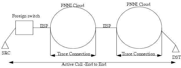
Figure 11-1 shows the section within which a call can be traced. For instance, you could start the trace for a call setup between SRC and DST. The Trace Connection message would terminate at the IISP interface and an ACK/NACK would be sent back (similar to as if its a UNI). This would enable the user to complete a partial trace.
Figure 11-1 Connection Trace in PNNI and IISP Network
Path Trace
Path Trace facility allows you to trace calls in real time. You enable or disable this feature node wide, on a per UNI interface basis or based on called party/calling party number. When enabled, the source node adds a TTL IE as part of the Setup/AddParty message and subsequent nodes supporting this feature add their own TTL IE. Various flags can be turned ON/OFF as part of the TTL on the source node, enabling a user to filter details on the trace. These flags are:
1.
2.
3.
Note
4.
5.
Path trace information for all the traced calls are stored in the trace log file, where they can be display information on the CLI screen.
Path Trace Success
The information from the response message is displayed using show commands. This information includes the TTL IEs and result of the return code.
Path Trace Failure:
Path trace fails due to similar reasons specified above for Connection Trace Fail. However, since this is a real-time trace, the node detecting the failure fills in the proper information in TTL IE, apart from filling up the Release Message.
An IISP interface is treated similarly to a UNI interface and the trace is terminated.
SES CLI Pathtrace Commands
The Pathtrace commands are as follows:
Their syntax is described in Appendix B, "SVC, SPVC, and PNNI Commands."
pathtrace-node
If path trace is enabled, the source node adds the TTL IE in the Setups depending on the flags set. The via node processes this IE and adds the relevant octets into the IE.
The signaling stack checks this flag before decoding TTL IE in an incoming setup message. It then checks this flag before starting TTL IE encoding procedures for an outgoing call.
pathtrace-if
This command is for incoming calls on a source node. Signalling checks these flags/parameters before generating/decoding the TTL IE. If the user selects disable, the rest of the parameters are ignored.
pathtrace-ie
This command is used for interoperability, when the Cisco SES PNNI controller is connected to equipment which does not support path trace. It takes two options, described below.
•
This command option allows you to control/handle Path trace on a interface level, when the PNNI network is connected to another through an IISP link, or to another PNNI network which does not support this facility. When this command is issued, TTL IE would be removed from all subsequent Setup messages going out on that interface, and would be reinserted to Connect/Release/Rls_Comp messages coming back for the same call. This ensures interoperability with other vendors' switches. All other flags would be ignored when issued with the removeIE flag. It would also remove the TTL IE from the connect message going out on that interface.
•
This option inserts the TTL IE to any incoming Setup/Connect message. The direction of this option is exactly opposite of removeIE option. Both these options can be applied on any interface on any via node.
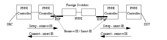
Figure 11-2 illustrates a sample network with pathtrace insert and remove IEs.
Figure 11-2 Insert and Remove IEs
The Cisco SES PNNI controller supports Connection Trace and Path trace facility for maximum 10 hops network and maximum 5 traces are allowed to be in progress at a time. The trace log file is recycled every time it reaches 1MByte in size.
 Feedback
Contact Cisco
- Open a Support Case

- (Requires a Cisco Service Contract)