Chapter 5: ATM Soft Permanent Virtual Circuits
Available Languages
Table Of Contents
ATM Soft Permanent Virtual Circuits
SPVC Endpoint Address and Default Traffic Parameters
Default Traffic Parameter Templates for Service Categories
SPVC Provisioning and Operation
Force De-route/Re-route of SPVC
Connection Configuration/Route
ATM Soft Permanent Virtual Circuits
ATM Soft Permanent Virtual Circuits (SPVCs), as implemented by the SES node, are described in the following topics:
•
SPVC Endpoint Address and Default Traffic Parameters
•
•
•
•

Note
Overview
SPVC connection provisioning can be done through an external Network Management System, such as Cisco Wan Manager (NMS), or via the command line interface. Only 2-end provisioning is supported in this release. When provisioning is done on an NMS, an SNMP set request is sent to both the SPVC endpoints terminating at the CPE ports.
SPVC provisioning includes:
•
•
•
•
•
Figure 5-1 shows an example of an end-to-end SPVC connection provisioning and establishment.
Figure 5-1 SPVC Provisioning
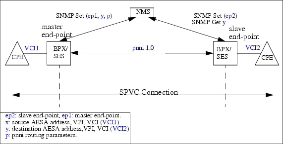
The end-points are reserved on the service modules prior to routing. The connection request is forwarded to the PNNI Controller. The SPVC is routed from the master endpoint to the slave endpoint.
The provisioning of multi-service SPVC on a switch and controller is performed as follows:
1.
2.
3.
4.
5.
6.
7.
For a more detailed description of provisioning a multiservice SPVC on a switch and controller, see Chapter 10, "Configuring ATM SVCs, PNNI Routing, and SPVCs".
SPVC Features
Table 5-1 describes the SPVC features supported for BPX-SES.
SPVC Endpoint Address and Default Traffic Parameters
The following sections discuss the provisioning of SPVC Endpoint Addresses and default traffic parameter templates for service categories.
SPVC Endpoint Address
The SPVC end-point routing references (referred to as x and y in Figure 5-2), returned by the connection provisioning modules after provisioning, are expressed in ATM AESA address, VPI, VCI.
Figure 5-2
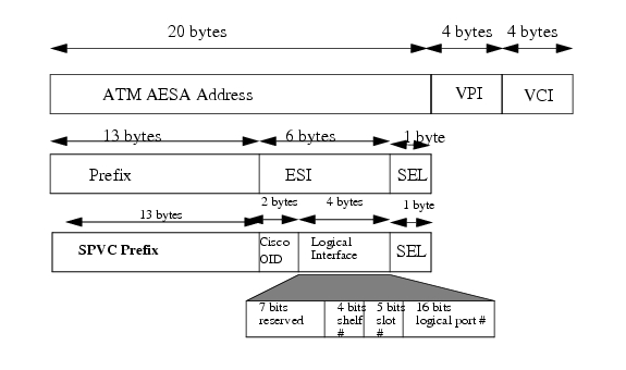
SPVC Routing Address
The x and y SPVC endpoints are expressed in (NASP address + VPI + VCI) as shown in Figure 5-2 above. They are assigned by the connection provisioning module for cross-reference with the end-points (ep1, ep2).
The default SPVC prefix is set to be the default PNNI node prefix. The SPVC prefix is initially set to 47.0091.81000000, but can be changed with the cnfspvcprfx command.
Default Traffic Parameter Templates for Service Categories
The SPVC commands do not contain all the fields needed for ABR service categories. PNNI controller provides templates with default values for all service categories for every interface. The user can modify these values as needed with the cnfcon command and the values are used for PNNI routing.
There are parameters that PNNI 1.0 signaling requires, but are not provided by the networking parameters, like the CDVT or MBS, they are configured at PNNI controller per interface. Refer to the SPVC CLI for setting default templates.
Table 5-2
ABR Parameters
SPVC Provisioning and Operation
The following sections describe SPVC provisioning and operation:
•
Adding/Deleting an SPVC
Use NMS or the command line interface to add and delete an SPVC.
To add an SPVC, perform the following steps:
Step 1
Step 2
Once the master endpoint is added, an SVC call setup establishes the SPVC.
To delete an SPVC, follow these steps:
Step 1
Step 2
Note
Note
Downing/Upping an SPVC
Use the NMS or the dncon and upcon commands to down or up connections.
When an SPVC is down, the SVC portion of the connection is released. The connection remains down until it is upped again by the user.
When an up request is received for a downed connection, the master endpoint will attempt to re-establish the connection.
The up and down request are only applicable to master endpoints. The request is rejected if issued to a slave endpoint.
Connection Modification
Use the NMS or the cnfcon command to modify connection parameters of an SPVC. The SPVC connection will be released and re-established. Depending on the bandwidth availability, no new path may be found, or the newly established path may be different from the original path.
Possible Provisioning Errors
The PNNI controller generates the following Provisioning Response error strings for SPVC connection addition failure:
Route/Re-route Retry
The master endpoint establishes the SPVC after it is provisioned. The first route attempt is immediate. If the first route attempt fails, subsequent retries are controlled by the "Fast Retry Interval Base" and the "Slow Retry Interval." Retries are separated by the following algorithm until the fast retry interval is larger than the slow retry interval:
(Fast Retry Interval Base * (2 ^ (# of attempts - 1)))
The succeeding retries will happen in every slow retry interval. There is no limit on the number of retries. Connections which are not established will be tried until they are successfully routed. This retry algorithm also applies to SPVCs which are released due to a network failure. SPVCs are re-established following the retry policy.
To ensure fairness in connection routing, unrouted connections are selected in a round robin fashion. To control congestion, a throttling scheme will be used to manage routing. These values can be configured on PNNI as nodal parameters through the cnfnodalcongth command.
Manual Reroute of SPVC
Use the NMS or the rrtcon command to manually reroute an SPVC. The SPVC connection will be re-routed to the best available path. The reroute request is only applicable to the master endpoints.
Note
Force De-route/Re-route of SPVC
Use the dnpnport and uppnport commands to down a port. The deroute and reroute behavior depends on whether the downed port is a UNI or NNI as follows:
•
•
•
SPVC Call Blocking
Use the NMS or the cnfpnportcc command to enable/disable the SPVC Call Blocking option. If this SPVC Call Blocking is enabled on a port, no new provisioning requests for SPVC will be accepted by the port. SPVC calls that are already added/established will not be affected.
Connection Trace
Use the NMS or the conntrace command to trace the established path for an SPVC.
Connectivity Verification
Use the NMS or the tstdelay or tstconseg commands to request a continuity test between two endpoints of an SPVC.
Route Optimization
In the PNNI network, SPVC connections are established using the best available path at the time the connections are routed. Upon a network failure, SPVC connections are re-routed to an alternate path. However, this newly selected path may not be the optimal path for the connection. When the network failure is recovered, the SPVC connections shall be re-routed to optimize the network usage. It is a background SPVC management option, once enabled, it will try to find a better path for those SPVCs that are specified by the user. If a better path is found, the SPVC will be released from its current path and re-routed to the better path. A better path is a path which its administrative weight is less than the administrative weight of the current path by a certain percentage specified by the user.
Route Optimization Commands
Use the following commands to optimize the paths of SPVC connections:
The user can query the route optimization status while it is in progress.
Note
SVC/SPVC Co-Existence
Currently SVC and SPVC connections both share the same pool of VPI resources on a port. Therefore, the VPI/VCI that is requested for an SPVC may already be used by an SVC. If this happens, the SPVC provisioning request will be rejected by the Service Module or by the PNNI controller depending on which module detects the collision. To avoid this problem, check the following:
•
•
Event Logging
Operation and exception events dealing with SPVCs are logged into the event log files. The event as well as the time it took place are entered into the log.
Considering the performance impacts of event logging and the potential for large numbers of SPVC related events occurring at one time, a CLI command is supported to enable or disable the logging of SPVC routing and status events.
SPVC Redundancy
Persistent Endpoints
The PNNI Control maintains the persistency of the routing parameters of the SPVC endpoint. The endpoint specify configuration is maintained in the endpoint database of the SPVCM.
Connection Configuration/Route
The routing parameters and endpoint database of the SPVC connection are stored redundantly in non-volatile storage as well as on the standby processor. The platform software provides the interface for storing the redundant data.
The path information of the SPVC connection is transient, and is removed from the call database once the call becomes active.
Rebuild
The controller re-establishes (re-route) connections after a processor reset.
Switchover
A switchover of the processor will not cause a disruption to the connectivity nor state of the SPVCs. The status of the endpoints will need to be re-synchronized between the controller and the service modules. Also, the state of the SPVC connections are re-synchronized with the neighbor (PNNI trunk) interfaces.
Connection Alarm Management
Connection alarm management provides the interface between the PVC aspects of an SPVC and the SVC aspects of an SPVC. Connection state must be reported across this interface and signalled across the network between the SPVC endpoints in both directions as shown in Figure 5-3. Connection status is reported to the CPE via the ILMI/LMI signalling or by using OAM flows. ILMI/LMI agents and OAM agents are resident on the line cards.
Figure 5-3
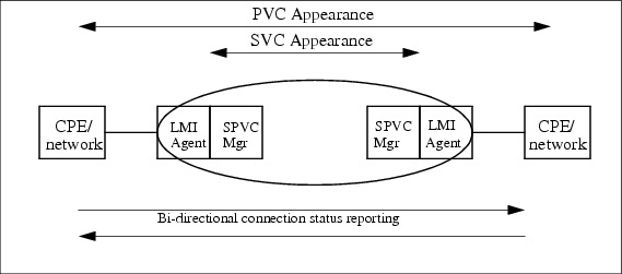
SPVC Status Reporting
An SPVC connection status can change due to a number of reasons as stated below:
1.
2.
3.
4.
5.
6.
7.
For failure case 1 and 2, the AIS cells have to be generated on all affected SPVCs into the network from the point of failure; this will be done by the service module.
The SM in BPX will do the following. (Figure 5-4 illustrates this case.)
•
•
Figure 5-4 Interface Failure at Network Edge and AIS Generation Into the Network
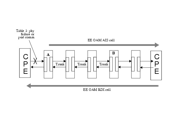
For failure case 3 and 4, at the moment of failure, all the affected SPVCs go into the de-routed state, and as long as alternate routes are not available the port-endpoints are made to generate AIS out the ports at the edge of the network. There are 4 steps involved as illustrated in Figure 5-5. Note that entities on either side of the trunk will detect the failure and execute the following:
1.
2.
3.
4.
If re-routing is possible for any SPVCs, the controllers will re-route those SPVCs and this will automatically stop the AIS flows (and consequently the RDI flows) on those SPVCs.
Figure 5-5
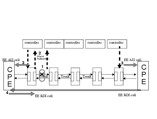
Interface Failure at a Trunk and AIS Generation Prior to Re-route
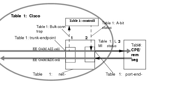
For failure case 5, if there is a feeder trunk or a CPE running LMI/ILMI at the edge of the network, SPVC failures (and their clearing) from the network side must be notified to the equipment using LMI STATUS_UPDATE messages/ILMI connection status traps. SPVC failures (from the network side) and their clearing are to be the detected based on the presence/absence of AIS cells flowing through the SPVC towards the CPE/feeder. The AIS state of an SPVC is detected at the INGRESS of the trunk-endpoint of SM in BPX. The controller is made known of the SPVC failures through bulk connection state traps by the SM in the BXM card which host the trunk-endpoint as shown in Figure 5-6.
The AIS state changes and SPVC status updates to the CPE/remote segment can be done in 3 steps as shown in :
1.
2.
3.
Figure 5-6 Detection of AIS SPVC Status Update to CPE/Remote Segment
For failure case 6, when a SPVC changes state (FAIL to ACTIVE or ACTIVE to FAIL) in an external segment connected via a feeder trunk (or an interface running LMI/ILMI), it will be indicated through A-bit changes in the LMI STATUS_UPDATE messages (or ILMI connection state traps in case of ILMI). This interface which is at the edge of the network must transport the remote segment SPVC state changes to the other end. This can be implemented by injecting AIS cells on the SPVC experiencing the A-bit failure into the network. At the other edge of the network, the AIS cells will be detected and corresponding A-bit status generated. When the A-bit failure clears at the local end, the AIS generation will be stopped and the remote end will indicate A-bit clear status. This mechanism is illustrated in Figure 5-7.
Figure 5-7
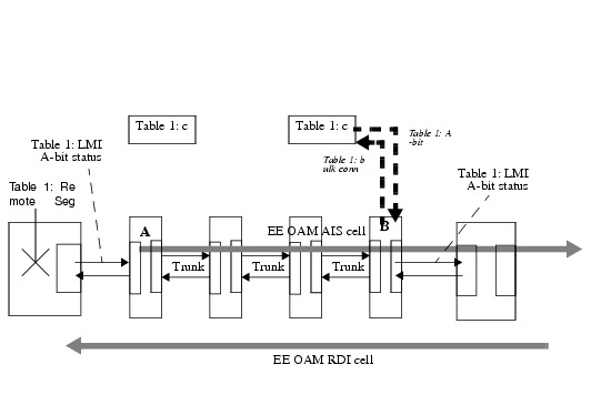
Transporting Remote Segment Failure Through AIS in the Network
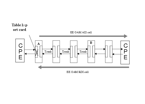
For failure case 7, the AIS cells have to be generated on all affected SPVCs into the network from the point of failure; this will be done by the SM and controller as follows:
1.
2.
Figure 5-8 illustrates this case.
Figure 5-8 Port Card Failure at the Network Edge and AIS Generation Into the Network
Reporting mechanism
There are two kinds of connection traps:
•
•
Connection traps are reported when:
•
•
When an alarm summary count trap is sent to the NMS, the NMS queries for a list of connections in alarm and their exact status.
Table 5-3 describes supported connection traps.
Table 5-3 Connection Traps
TRAP Literal1
Trap description
Severity
Information Provided
TRAP_CHAN_ADDED
60301Trap generated when a new connection is added
Information
(a) ifIndex
(b) VPI and VCI if applicable
(c) Upload configuration counter
TRAP_CHAN_DELETED
60302Trap generated when a
connection is deletedInformation
(a) ifIndex
(b) VPI (and VCI if applicable)
(c) Upload configuration counter
TRAP_CHAN_ACTIVE
60302
Trap generated when a connection is out of alarm condition
Information
(a) ifIndex
(b) VPI (and VCI if applicable))
(c) Upload configuration counter
TRAP_CHAN_MODIFIED
60305Trap generated when a
connection is modifiedInformation
(a) fIndex
(b) VPI (and VCI if applicable)
(c) Upload configuration counter
TRAP_CHAN_FAILED
60304
Trap generated when a connection are transitioning to failed from cleared state.
Information
(a) fIndex
(b) VPI (and VCI if applicable)
(c) Alarm Status
TRAP_CHAN_SUM_COUNT
60306
When number of connection traps exceeds maximum traps per reporting interval
Information
(a) summary connection alarm count
TRAP_CHAN_DOWNED
60307
Trap generated when a connection is administratively down
Information
(a) fIndex
(b) VPI (and VCI if applicable))
(c) Alarm Status
1 Trap numbers 60301- 60307 are reserved for BPX SPVC Traps.
Alarm throttling
Alarm will be generated when an interface or a connection failed. Connection alarms usually occur in a "burst" and when they do, the system should not buckle under the instantaneous load. Hence several measures are adopted to throttle the alarm reporting:
1.
2.
3.
SPVC Stats Collection
The collected SPVC statistics allow you to properly engineer and overbook the network. SPVC statistics also provide accounting functionality for the SPVC feature. The following figure provides the architectural overview of the PXM BPX SPVC Statistics system.
Figure 5-9 BPX/SES SPVC Stats Collection Architecture
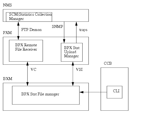
The stats collection operates as follows:
1.
2.
3.
4.
 Feedback
Contact Cisco
- Open a Support Case

- (Requires a Cisco Service Contract)