Table Of Contents
SNMP Management Information Base
SNMP Fundamentals
MIB Tree
MIB Objects Overview
Object Identifier
Object Definitions
SNMP Traps
MIBs Supported by the PNNI Controller
ATM MIB Objects
atmInterfaceConfTable
PNNI MIB Objects
pnniBaseGroup
pnniNodeTable
pnniNodePglTable
pnniNodeTimerTable
pnniNodeSvccTable
pnniScopeMappingTable
pnniLinkTable
pnniSummaryAddressTable
Cisco WAN SVC MIB Objects
ciscoWANSvcInfo
CiscoWANSpvc Port
cwspConnTrace
Cisco WAN ATM MIB Objects
cwAtmChanCfgTable
CwAtmChanStateTable
CwAtmChanTestTable
SNMP Management Information Base
The SES PNNI Controller SNMP implementation uses the MGX 8800's distributed Management Information Base. In this implementation, a master agent resides on a PXM card. A subagent also resides on the PXM to support the PNNI application.
This appendix contains the following sections:
• SNMP Fundamentals
•MIBs Supported by the PNNI Controller
SNMP Fundamentals
A network management system contains several (potentially many) nodes, each with a processing entity—termed an agent—which has access to management instrumentation, at least one management station, and a management protocol that conveys management information between the agents and management stations.
Network management stations execute management applications which monitor and control network elements. Network elements are devices such as hosts, routers, terminal servers, etc., which are monitored and controlled through access to their management information.
Management information is viewed as a collection of managed objects. Collections of related objects are defined in Management Information Base (MIB) modules. These modules are written using a subset of OSI's Abstract Syntax Notation One (ASN.1), termed the Structure of Management Information (SMI).
The management protocol, SNMP, provides for the exchange of messages which convey management information between the agents and the management stations.
MIB Tree
Figure E-1 shows the MIB tree from its root, "iso", to some of its lower branches. The branches of primary interest are "mgmt" and "private." The mgmt branch contains standard MIBs and the private branch contains enterprise MIBs. Private enterprises obtain branch number assignments from the Internet Assigned Numbers Authority (IANA). Cisco developers obtain branch number assignments in the Cisco branch from the Cisco Assigned Numbers Authority (CANA).
Figure E-1 MIB Tree
The following OIDs all refer to the same place in the tree:
iso.org.dod.internet.mgmt.mib-2.system
iso.org.dod.internet.2.1.1
An object is a leaf on such a tree. For example, sysDescr is an object in the System branch of MIB-II. The unique identification of an object comprises the list of branch points down to the object plus an instance identifier. The instance identifier for an ordinary, single instance (scalar) object is always zero, so the full OID for sysDescr is:
iso.internet.mgmt.mib-2.system.sysDescr.0
Or, numerically:
Some Table objects can have more than one instance, but that's a separate topic.
MIB Objects Overview
A primary component of SNMP is the MIB, defining data for observation and control and asynchronous notifications (Trap in SNMPv1).
The SNMP MIB is conceptually a tree structure with table, the leaves of MIB tree are individual items of data called objects.
Object Identifier
An object identifier uniquely designates any point in the tree, whether leaf object or branch point. An object identifier may be expressed as a series of integers or text strings. The numeric form is used in the protocol among machines. The text form, sometimes mixed with the numeric form is for use by people. Technically, the numeric form is the object name and the text form is the object descriptor. In practise, either is usually called an object identifier or OID.
Object Definitions
An object definition contains following fields: SYNTAX, MAX-ACCESS, STATUS, DESCRIPTION, IndexPart, and DefValPart:
			      data types -- please see data type table below for primitive data types allowed by
the SNMP SMI, and Textual conventions.
| "accessible-for-notify"
The MIB object data types are shown in the following table.
|
Data Type
|
Description
|
|
primitive type
|
|
INTEGER |
Integer-valued information between (-2147483648 to 2147483647) |
OCTET STRING |
String of bytes of length 0 to 65,535 |
OBJECT IDENTIFIER |
Numeric ASN-1-type object identifier |
Integer32 |
Integer-valued information between (-2147483648 to 2147483647) |
Unsigned32 |
Unsigned Integer-valued information between (0 to 2147483647) |
Counter32 |
Represents a non-negative integer which monotonically increases until it reaches a maximum value of (4294967295 decimal), when it wraps around and starts increasing again from zero |
TimeTicks |
Period of time, measured in units of 0.01 seconds,
INTEGER (0..4294967295) |
|
Textual Convention
|
|
TimeStamp |
Value of the sysUpTime object at which a specific occurrence happened. The specific occurrence must be defined in the description of any object defined using this type, TimeTicks |
TruthValue |
Represents a boolean value, INTEGER { true(1), false(2) } |
DisplayString |
OCTET STRING (SIZE (0..255)) |
AtmAddress |
ATM End-System Addresses, OCTET STRING (SIZE (8 | 20)) |
NetPrefix |
Network-Prefixes for an ATM Address, OCTET STRING (SIZE (8 | 13)) |
IpAddress |
Represents a 32-bit internet address. It is in network byte-order, OCTET STRING (SIZE (4)) |
RowStatus |
Manages the creation and deletion of rows, and is the value of the SYNTAX clause for the status column of a row. |
CiscoAtmServiceCategory |
The ATM forum service categories. Additionally, ABR foresight service type is also supported. The valid values are: cbr1(1), vbr1RT(2), vbr2RT(3), vbr3RT(4), vbr1nRT(5), vbr2nRT(6), vbr3nRT(7), ubr1(8), ubr2(9), abr(10), cbr2(11), and cbr3(12). |
CiscoWanLpbkTypes |
Defines possible loopback configurations for a connection: noLpbk(1) : no loopback or clear configured loopback destructive(2) : loopback all cells, causing data disruption. nonDestructive(3) : loopback performed using OAM loopback cells. Does not disrupt regular traffic. |
CiscoWanLpbkDir |
Direction in which looped should be effected: external (1): loop port traffic back to port. Applicable only for destructive mode. internal(2) : loop switch's egress traffic back to switch. Applicable only for destructive mode. forward(3) : inject OAM loopback cells towards the switching fabric (ingress). Applicable only for non-destructive mode. reverse(4) : inject OAM loopback cells towards the port (egress). Applicable only for non-destructive mode. |
CiscoWanTestStatus |
Defines possible loopback test status at an endpoint.noStatus (1), The valid values are : lpbkInProgress(2), lpbkSuccess(3), lpbkAbort(4), lpbkTimeOut(5), lpbkInEffect(6) |
CiscoWanNsapAtmAddress |
ATM address used by the networking entity. The only address type presently supported is NSAP (20 octets). OCTET STRING (SIZE(20)) |
CiscoWanAlarmState |
Defines possible alarms at an endpoint: ingAisRdi(1) : Endpoint receiving AIS or RDI cells in ingress direction egrAisRdi(2) : Endpoint receiving AIS or RDI cells in egress direction conditioned(4) : Networking entity has forced the endpoint out of service. This could be attributed to either routing failure or to a maintenance operation initiated by the networking entity. interfaceFail(8) : The interface to which this connection belongs has failed. ccFail (16) : The OAM continuity check between the connection and its peer endpoint has detected a failure. mismatch(32) : connection exists in SM database, but not in the network controller database ingAbitFail(64) : Feeder connection detects A-bit failure in the ingress direction |
CiscoWanXmtState |
Defines possible transmit states of an endpoint: normal(1) : Endpoint transmitting normal traffic. sendingAIS(2) : Endpoint inhibits regular traffic, sends AIS on egress sendingRDI(3) : Endpoint inhibits regular traffic, sends AIS on egress |
CiscoWanRcvState |
Defines possible receive states of an endpoint normal(1) : Endpoint receiving normal traffic. receivingAIS(2) : Endpoint receiving AIS, in either ingress/egress receivingRDI(3) : Endpoint receiving RDI, in either ingress/egress ccFailure(4) : Endpoint does not receive OAM CC cells |
CiscoWanERSConfg |
Defines possible configuration for Explicit Rate Stamping (ERS): None(1) : Disable the ERS on connection enableIngress(2) : Enable ERS in the Ingress direction ONLY enableEgress(3) : Enable ERS in the Engress direction ONLY enableBoth(4) : Enable ERS in both direction |
CiscoWanVSVDConfg |
Defines possible VSVD configuration applicable to an endpoint: vsvdOff (1) : Disable VSVD vsvdOn(2) : Enable VSVD switchDefault(3) : Use default settings on switch. |
CiscoWanAisIW |
Defines an SPVC endpoint's AIS capability: e2eAisCapable(1) : Endpoint capable of detecting/generating e2e AIS. segAisCapable(2) : Endpoint capable of detecting/generating seg AIS. |
AbrRateFactors |
Defines possible rate factors to be used in increasing/decreasing ABR cell rate. The valid values are: oneOver32768(1), oneOver16384(2), oneOver8192(3), oneOver4096(4), oneOver2048(5), oneOver1024(6), oneOver512(7), oneOver256(8), oneOver128(9), oneOver64(10), oneOver32(11), oneOver16(12), oneOver8(13), oneOver4(14), oneOver2(15), one(16) |
SNMP Traps
A trap is an unsolicited message sent by an agent to a registered SNMP management stations. The purpose is to notify the management stations of some unusual event. Traps provide management stations with the following information:
•The network management subsystem that generated the trap (Enterprise)—Identifies the network management subsystem that generated that trap.
•IP address of the object generating the trap (Agent-addr).
•Generic trap type (Generic)—Pre-defined trap type, RFC1157 generic trap types includes coldStart, warmStart, linkDown, linkUp, authenticationFailure, egpNeighborLoss and enterpriseSpecific.
•Specific trap type (Specific)—If the value of Generic Trap Type is enterpriseSpecific, this specific trap type field contains a number that indicates a CISCO specific trap.
•The time between the last initialization of the network entity that issued the trap and the generation of the Atropatene Ticks).
•"Interesting" information (Varbind List)—Additional information relating to the trap (The significance of this field is implementation-specific).
MIBs Supported by the PNNI Controller
•ATM MIB Objects
•PNNI MIB Objects
•Cisco WAN ATM MIB Objects
ATM MIB Objects
•atmInterfaceConfTable
atmInterfaceConfTable
The atmInterfaceConfTable contains ATM local interface configuration parameters, one entry per ATM interface port. Althought the are many attributes for the table, SES only supports atmInterfaceMyNeighborIpAddress and atmInterfaceMyNeighborIfName both as read-only access.
.
Table E-1 atmInterfaceConfTable Entries
|
No.
|
Object Type
|
Access
|
Description
|
Default
|
11 |
atmInterfaceMyNeighborIpAddress |
Read-Write |
IP address of the neighbor system connected to the far end of this interface, to which a network management station can send SNMP messages, as IP datagrams sent to UDP port 161, in order to access network management information concerning the operation of that system.
Note The value of this object may be obtained by using various methods, such as manual configuration, or through ILMI interaction with the neighbor system.
|
|
12 |
atmInterfaceMyNeighborIfName |
Read-Write |
Text name of the interface on the neighbor system at the far end of this interface, and to which this interface connects. If the neighbor system is manageable with SNMP and supports the object ifName, the value of this object must be identical with that of ifName for the ifEntry of the lowest level physical interface for this port. If this interface does not have a a text name, the value of this object is a zero length string.
Note The value of this object may be obtained by using various methods, such as manual configuration, or through ILMI interaction with the neighbor system.
|
|
PNNI MIB Objects
•pnniBaseGroup
•pnniNodeTable
•pnniNodePglTable
•pnniNodeTimerTable
•pnniNodeSvccTable
•pnniScopeMappingTable
•pnniLinkTable
•pnniSummaryAddressTable
pnniBaseGroup
Table E-2 pnniBaseGroup
|
No.
|
Object Type
|
Access
|
Description
|
Default
|
1 |
pnniHighestVersion |
Read Only |
The highest version of the PNNI protocol that the software in this switching system is capable of executing.
Reference: ATM Forum PNNI 1.0 Section 5.6.1
|
|
2 |
pnniLowestVersion |
Read Only |
The lowest version of the PNNI protocol that the software in this switching system is capable of executing.
Reference: ATM Forum PNNI 1.0 Section 5.6.1
|
|
3 |
pnniDtlCountOriginator |
Read Only |
The total number of DTL stacks that this switching system has originated as the DTLOriginator and placed into signaling messages. This includes the initial DTL stacks computed by this system as well as any alternate route (second, third choice etc.) DTL stacks computed by this switching system in response to crankbacks |
|
4 |
pnniDtlCountBorder |
Read Only |
The number of partial DTL stacks that this switching system has added into signaling messages as an entry border node. This includes the initial partial DTL stacks computed by this system as well as any alternate route (second, third, choice, etc.) partial DTL stacks computed by this switching system in response to crankbacks. |
|
5 |
pnniCrankbackCountOriginator |
Read Only |
The count of the total number of connection setup messages including DTL stacks originated by this switching system that have cranked back to this switching system at all levels of the hierarchy. |
|
6 |
pnniCrankbackCountBorder |
Read Only |
The count of the total number of connection setup messages including DTLs added by this switching system as an entry border node that have cranked back to this switching system at all levels of the hierarchy. This count does not include Crankbacks for which this switching system was not the crankback destination, only those crankbacks that were directed to this switching system are counted here. |
|
7 |
pnniAltRouteCountOriginator |
Read Only |
The total number of alternate DTL stacks that this switching system has computed and placed into signaling messages as the DTL originator. |
|
8 |
pnniAltRouteCountBorder |
Read Only |
The total number of alternate partial DTL stacks that this switching system has computed and placed into signaling messages as a entry border node. |
|
9 |
pnniRouteFailCountOriginator |
Read Only |
The total number of times where the switching system failed to compute a viable DTL stack as the DTL originator for some call. It indicates the number of times a call was cleared from this switching system due to originator routing failure. |
|
10 |
pnniRouteFailCountBorder |
Read Only |
The total number of times where the switching system failed to compute a viable partial DTL stack as an entry border node for some call. It indicates the number of times a call was either cleared or cranked back from this switching system due to border routing failure. |
|
11 |
pnnieRouteFailUnreachableOriginator |
Read Only |
The total number of times where the switching system failed to compute a viable DTL stack as the DTLOriginator because the destination was unreachable; for example, those calls that are cleared with cause #2 `specified transit network unreachable' or cause #3 `destination unreachable' in the cause. |
|
12 |
pnniRouteFailUnreachableBorder |
Read Only |
The total number of times where the switching system failed to compute a viable partial DTL stack as an entry border node because the target of the path calculation was unreachable; for example, those calls that are cleared or cranked back with cause #2 `specified transit network unreachable' or cause #3 `destination unreachable' in the cause. |
|
pnniNodeTable
The pnniNodeTable collects attributes that affect the operation of a PNNI logical node.
Note createAndWait is not supportedas a rowStatus value for the pnniNodeRowStatus attribute.
Reference: ATM Forum PNNI 1.0 Annex F.
Table E-3 pnniNodeTable
|
No.
|
Object Type
|
Access
|
Description
|
Default
|
1 |
pnniNodeIndex |
none |
A value assigned to a node in this switching system that uniquely identifies it in the MIB. |
|
2 |
pnniNodeLevel |
Read-Create |
The level of PNNI hierarchy at which this node exists. This attribute is used to determine the default node ID and the default peer group ID for this node. This object may only be written when pnniNodeAdminStatus has the value down.
Reference: ATM Forum PNNI 1.0 Section 5.3.1 Annex F.
|
96
|
3 |
pnniNodeId |
Read-Create |
The value the switching system is using to represent itself as this node. This object may only be written when pnniNodeAdminStatus has the value down. If pnniNodeLowest is true, then the default node ID takes the form defined in Section 5.3.3 for lowest level nodes, with the first octet equal to pnniNodeLevel, the second octet equal to 160, and the last 20 octets equal to pnniNodeAtmAddress. If pnniNodeLowest is false, then the default node ID takes the form defined in Section 5.3.3 for logical group nodes, with the first octet equal to pnniNodeLevel, the next fourteen octets equal to the value of pnniNodePeerGroupId for the child node whose election as PGL causes this LGN to be instantiated, the next six octets equal to the ESI of pnniNodeAtmAddress, and the last octet equal to zero. |
|
4 |
pnniNodeLowest |
Read-Create |
Indicates whether this node acts as a lowest level node or whether this node is a logical group node that becomes active when one of the other nodes in this switching system becomes a peer group leader. The value "false" must not be used with nodes that are not PGL/LGN capable. This object may only be written when pnniNodeAdminStatus has the value "down". |
|
5 |
pnniNodeAdminStatus |
Read-Create |
Indicates whether the administrative status of the node is "up" (the node is allowed to become active) or "down" (the node is forced to be inactive). When pnniNodeAdminStatus is down, then pnniNodeOperStatus must also be "down". |
Up
|
6 |
pnniNodeOperStatus |
Read-Only |
Indicates whether the node is active or whether the node has yet to become operational. When the value is down, all state has been cleared from the node and the node is not communicating with any of its neighbor nodes. |
|
8 |
pnniNodeAtmAddress |
Read-Create |
This node's ATM End System Address. Remote systems wishing to exchange PNNI protocol packets with this node should direct packets or calls to this address. This attribute may only be written when pnniNodeAdminStatus has the value down.
Reference: ATM Forum PNNI 1.0 Section 5.2.2
|
|
9 |
pnniNodePeerGroupId |
Read-Create |
The Peer Group Identifier of the peer group that the given node is to become a member of. The default value of this attribute has the first octet equal to pnniNodeLevel, the next pnniNodeLevel bits equal to the pnniNodeLevel bits starting from the third octet ofpnniNodeId, and the remainder padded with zeros. This object may only be written when pnniNodeAdminStatus has the value down.
Reference: ATM Forum PNNI 1.0 Section 5.3.2, Annex F
|
|
10 |
pnniNodeRestrictedTransit |
Read-Create |
Specifies whether the node is restricted to not allowing support of SVCs transiting this node. This attribute determines the setting of the restricted transit bit in the nodal information group originated by this node.
Reference: ATM Forum PNNI 1.0 Section 5.8.1.2.3
|
|
11 |
pnniNodeComplexRep |
Read-Create |
Specifies whether this node uses the complex node representation. A value of `true' indicates that the complex node representation is used, whereas a value of `false' indicates that the simple node representation is used. This attribute determines the setting of the nodal representation bit in the nodal information group originated by this node.
Reference: ATM Forum PNNI 1.0 Section 5.8.1.2.3
|
|
12 |
pnniNodeRestrictedBranching |
Read-Only |
Indicates whether the node is able to support additional point-to-multipoint branches. A value of "false" indicates that additional branches can be supported, and a value of "true" indicates that additional branches cannot be supported. This attribute reflects the setting of the restricted branching bit in the nodal information group originated by this node.
Reference: ATM Forum PNNI 1.0 Section 5.8.1.2.3
|
|
13 |
pnniNodeDatabaseOverload |
Read-Only |
Specifies whether the node is currently operating in topology database overload state. This attribute has the same value as the Non-transit for PGL Election bit in the nodal information group originated by this node.
Reference: ATM Forum PNNI 1.0 Section 5.8.1.2.3
|
|
14 |
pnniNodePtses |
Read-Only |
Gauges the total number of PTSes currently in this node's topology databases(s) |
|
15 |
pnniNodeRowStatus |
Read-Create |
To create, delete, activate, and deactivate a Node. |
|
pnniNodePglTable
Peer group leader election information for a PNNI node in this switching system.
Reference: ATM Forum PNNI 1.0 Section 5.10.1.
Table E-4 pnniNodePglTable
|
No.
|
Object Type
|
Access
|
Description
|
Default
|
1 |
pnniNodePglLeadershipPriority |
Read-Create |
The Leadership priority value this node should advertise in its nodal information group for the given peer group. Only the value zero can be used with nodes that are not PGL/LGN capable. If there is no configured parent node index or no corresponding entry in the pnniNodeTable, then the advertised leadership priority is zero regardless of this value
Reference: ATM Forum PNNI 1.0 Section 5.10.1.2
|
0
|
2 |
pnniNodeCfgParentNodeIndex |
Read-Create |
The local node index used to identify the node that represents this peer group at the next higher level hierarchy, if this node becomes peer group leader. Value 0 indicates that there is no parent node.
Reference: ATM Forum PNNI 1.0 Annex F
|
0
|
3 |
pnniNodePglInitTime |
Read-Create |
The amount of time in seconds this node will delay advertising its choice of preferred PGL after having initialized operation and reached the full state with at least one neighbor in the peer group.
Reference: ATM Forum PNNI 1.0 Annex G PGLInitTime
|
15
|
4 |
pnniNodePglOverrideDelay |
Read-Create |
The amount of time in seconds a node will wait for itself to be declared the preferred PGL by unanimous agreement among its peers. In the absence of unanimous agreement this will be the amount of time that will pass before the node considers a two thirds majority as sufficient agreement to declare itself peer group leader, abandoning the attempt to get unanimous agreement.
Reference: ATM Forum PNNI 1.0 Annex G OverrideDelay
|
30
|
5 |
pnniNodePglReelectTime |
Read-Create |
The amount of time in seconds after losing connectivity to the current peer group leader that this node will wait before re-starting the process of electing a new peer group leader.
Reference: ATM Forum PNNI 1.0 Annex G ReElectionInterval
|
15
|
6 |
pnniNodePglState |
Read-Only |
Reference: Indicates the state that this node is in with respect to the peer group leader election that takes place in the node's peer group. The values are enumerated in the peer group leader state machine.
Reference: ATM Forum PNNI 1.0 Section 5.10.1.1.2
|
|
7 |
pnniNodePreferredPgl |
Read-Only |
The Node ID of the node that the local node believes should be or becomes the peer group leader. This is also the value the local node is currently advertising in the "preferred peer Group Leader Node ID field of its nodal information group within the given peer group. If a Preferred PGL has not been chosen, this attribute's value is set to (all) zero(s).
Reference: ATM Forum PNNI 1.0 Section 5.10.1.1.6
|
|
8 |
pnniNodePeerGroupLeader |
Read-Only |
The Node Identifier of the node that is currently operating as peer group leader of the peer group this node belongs to. If a PGL has not been elected, this attribute's value is set to (all) zero(s). |
|
9 |
pnniNodePglTimeStamp |
Read-Only |
The time at which the current Peer Group Leader established itself. |
|
10 |
pnniNodeActiveParentNodeId |
Read-Only |
The Node Identifier value being used by the Peer Group Leader to represent this peer group at the next higher level of the hierarchy. If this node is at the highest level of the hierarchy or if no PGL has yet been elected the PNNI Protocol Entity sets the value of this attribute to (all) zero(s). |
|
pnniNodeTimerTable
A table of initial PNNI timer values and significant change thresholds.
Table E-5 pnniNodeTimerTable
|
No.
|
Object Type
|
Access
|
Description
|
Default
|
1 |
pnniNodePtseHolddown |
Read-Create |
The initial value for the PTSE hold down timer that will be used by the given node to limit the rate at which it can re-originate PTSEs. It must be a positive non-zero number.
Reference: ATM Forum PNNI 1.0 Annex G MinPTSEInterval
|
10
|
2 |
pnniNodeHelloHolddown |
Read-Create |
The initial value for the Hello hold down timer that will be used by the given node to limit the rate at which it sends Hellos. It must be a positive non-zero number.
Reference: ATM Forum PNNI 1.0 Annex G MinHelloInterval
|
10
|
3 |
pnniNodeHelloInterval |
Read-Create |
The initial value for the Hello Timer. In the absence of triggered Hellos, this node will send one Hello packet on each of its ports on this interval.
Reference: ATM Forum PNNI 1.0 Annex G HelloInterval
|
15
|
4 |
pnniNodeHelloInactiveFactor |
Read-Create |
The value for the Hello Inactivity factor that this node will use to determine when a neighbor has gone down.
Reference: ATM Forum PNNI 1.0 Annex G InactivityFactor
|
5
|
5 |
pnniNodeHlinkInact |
Read-Create |
The amount of time a node will continue to advertise a horizontal (logical) link for which it has not received and processed a LGN Horizontal Link information group.
Reference: ATM Forum PNNI 1.0 Annex G HorizontalLinkInactivityTime
|
120
|
6 |
pnniNodePtseRefreshInterval |
Read-Create |
The initial value for the Refresh timer that this node will use to drive (re-)origination of PTSEs in the absence of triggered updates.
Reference: ATM Forum PNNI 1.0 Annex G PTSERefreshInterval
|
1800
|
7 |
pnniNodePtseLifetimeFactor |
Read-Create |
The value for the lifetime multiplier, expressed as a percentage. The result of multiplying the pnniNodePtseRefreshInterval attribute value by this attribute value is used as the initial lifetime that this node places into self-originated PTSEs
Reference: ATM Forum PNNI 1.0 Annex G PTSELifetimeFactor
|
200
|
8 |
pnniNodeRxmtInterval |
Read-Create |
The period between retransmissions of unacknowledged Database Summary packets, PTSE Request packets, and PTSPs
Reference: ATM Forum PNNI 1.0 Annex G DSRxmtInterval
|
5
|
9 |
pnniNodePeerDelaydAckInterval |
Read-Create |
The minimum amount of time between transmissions of delayed PTSE acknowledgement packets. |
10
|
10 |
pnniNodeAvcrPm |
Read-Create |
The proportional multiplier used in the algorithms that determine significant change for AvCR parameters, expressed as a percentage.
Reference: ATM Forum PNNI 1.0 Section 5.8.5.2.5.4 Annex G AvCR_PM.
|
50
|
11 |
pnniNodeAvcrMt |
Read-Create |
The minimum threshold used in the algorithms that determine significant change for AvCR parameters, expressed as a percentage.
Reference: ATM Forum PNNI 1.0 Section 5.8.5.2.5.4 Annex G AvCR_mT
|
3
|
12 |
pnniNodeCdvPM |
Read-Create |
The proportional multiplier used in the alg9orithms that determine significant change for CDV metrics, expressed as a percentage.
Reference: ATM Forum PNNI 1.0 Section 5.8.5.2.5.6 Annex G CDV_PM
|
25
|
13 |
pnniNodeCtdPm |
Read-Create |
The proportional multiplier used in the algorithms that determine significant change for CTD metrics, expressed as a percentage.
Reference: ATM Forum PNNI 1.0 Section 5.8.5.2.5.5. Annex maxCTD_PM
|
50
|
pnniNodeSvccTable
The pnniNodeSvccTable is a table of variables related to SVCC-based routing control channels.
Table E-6 Nodal SVCC-based RCC Variables Table
|
No.
|
Object Type
|
Access
|
Description
|
Default
|
1 |
pnniNodeSvccInitTime |
Read-Create |
The amount of time this node will delay initiating establishment of an SVCC to a neighbor with a numerically lower ATM address, after determining that such an SVCC should be established.
Reference: ATM Forum PNNI 1.0 Annex G InitialLGNSVCTimeout.
|
4
|
2 |
pnniNodeSvccRetryTime |
Read-Create |
The amount of time this node will delay after an apparently still necessary and viable SVCC-based RCC is unexpectedly torn down before attempting to re-establish it.
Reference: ATM Forum PNNI 1.0 Annex G RetryLGNSVCTimeout.
|
30
|
3 |
pnniNodeSvccCallingIntegrityTime |
Read-Create |
The amount of time this node will wait for an SVCC, which it has initiated establishment of as the calling party, to become fully established before giving up and tearing it down.
Reference: ATM Forum PNNI 1.0 Annex G SVCCallingIntegrityTime
|
35
|
4 |
pnniNodeSvccCalledIntegrityTime |
Read-Create |
The amount of time this node will wait for an SVCC, which it has decided to accept as the called party, to become fully established before giving up and tearing it down.
Reference: ATM Forum PNNI 1.0 Annex G SVCCalledIntegrityTime
|
50
|
5 |
pnniNodeSvccTrafficDescriptiorIndex |
Read-Create |
A index into the atmTrafficDescrParamTable defined in RFC 1695. This traffic descriptor is used when establishing switched virtual channels for use as SVCC-based RCCs to/from PNNI logical group nodes.
Reference: ATM Forum PNNI 1.0 Section 5.5.2, Annex G RCCMaximumBurstSize, RCCPeakCellRate, RCCSustainableCellRate
|
|
pnniScopeMappingTable
The pnniScopeTable contains the mapping of membership and connection scope from organization scope values (used at the UNI interfaces) to PNNI scope (for example, in terms of PNNI routing level indicators).
Reference: ATM Forum PNNI 1.0 Section 5.3.6.
Table E-7 pnniScopeMappingTable
|
No.
|
Object Type
|
Access
|
Description
|
Default
|
1 |
pnniScopeLocalNetwork |
Read-Create |
The highest level of PNNI hierarchy (namely, smallest PNNI routing level) that lies within the organizational scope value localNetwork(1). |
96
|
2 |
pnniScopeLocalNetworkPlusOne |
Read-Create |
The highest level of PNNI hierarchy (namely, smallest PNNI routing level) that lies within the organizational scope value localNetwtorkPlusOne(1). |
96
|
3 |
pnniScopeLocalNetworkPlusTwo |
Read-Create |
The highest level of PNNI hierarchy (namely, smallest PNNI routing level) that lies within the organizational scope value localNetworkPlusTwo(3). |
96
|
4 |
pnniScopeSiteMinusOne |
Read-Create |
The highest level of PNNI hierarchy (namely, the smallest PNNI routing level) that lies within the organizational scope value siteMinusOne(4). |
80
|
5 |
pnniScopeInteraSite |
Read-Create |
The highest level of PNNI hierarchy (namely, the smallest PNNI routing level) that lies within the organizational scope value interaSite(5). |
80
|
6 |
pnniScopeSitePlusOne |
Read-Create |
The highest level of PNNI hierarchy (namely, the smallest PNNI routing level) that lies within the organizational scope value sitePlusOne(6). |
72
|
7 |
pnniScopeOrganizationMinusOne |
Read-Create |
The highest Level of PNNI hierarchy (namely, the smallest PNNI routing level) that lies within the organizational scope value organizationMinusOne(7). |
72
|
8 |
pnniScopeIntraOrganization |
Read-Create |
The highest level of PNNI hierarchy (namely, the smallest PNNI routing level) that lies within the organizational scope value intraOrganization(8). |
64
|
9 |
pnniScropeOrganizationPlusOne |
Read-Create |
The highest level of PNNI hierarchy (namely, the PNNI routing level) that lies within the organizational scope value organizationPlusOne(9). |
64
|
10 |
pnniScopeCommunityMinusOne |
Read-Create |
The highest level of PNNI hierarchy (namely, the smallest PNNI routing level) that lies within the organizational scope value communityMinusOne(10). |
64
|
11 |
pnniScopeIntraCommunity |
Read-Create |
The highest level of PNNI hierarchy (namely, the smallest PNNI routing level) that lies within the organizational scope value intrCommunity(11). |
48
|
12 |
pnniScopeCommunityPlusOne |
Read-Create |
The highest level of PNNI hierarchy (namely, the smallest PNNI routing level) that lies within the organizational scope communityPlusOne(1). value |
48
|
13 |
pnniScopeRegional |
Read-Create |
The highest level of PNNI hierarchy (namely, the smallest PNNI routing level) that lies within the organizational scope value regional(13). |
32
|
14 |
pnniScopeInterRegional |
Read-Create |
The highest level of PNNI hierarchy (namely, the smallest PNNI routing level) that lies within the organizational scope value interRegional(14). |
32
|
15 |
pnniScopeGlobal |
Read-Create |
The highest level of PNNI hierarchy (namely, the smallest PNNI routing level) that lies within the organizational scope value vlobal(15). |
0
|
pnniLinkTable
This table contains the attributes necessary to describe the operation of logical links attached to the local switching system and the relationship with the neighbor nodes on the other end of the links. Links are attached to a specific node within the switching system. A concatenation of the Node Index of the node within the local switching system and the port ID are used a the instance ID to uniquely identify the link. Links may represent horizontal links between lowest level neighboring peers, outside links, uplinks, or horizontal links to and from LGNs.
The entire pnniLink object is read-only, reflecting the fact that this information is discovered dynamically by the PNNI protocol rather than configured.
Reference: ATM Forum PNNI 1.0 Section 5.6.
Table E-8 pnniLinkTable
|
No.
|
Object Type
|
Access
|
Description
|
Default
|
1 |
pnniLinkPortId |
none |
The Port Identifier of the link as selected by the local node. This value has meaning only within the context of the node to which the port is attached. |
|
2 |
pnniLinkType |
Read-Only |
Indicates the type of link being described. |
|
3 |
pnniLinkVersion |
Read-Only |
For horizontal and outside links between lowest-level nodes and for links of unknown type, this attribute indicates the version of PNNI routing protocol used to exchange information over this link. If communication with the neighbor node has not yet been established, then the Version is set to "unknown". For uplinks (where the port ID is not also used for the underlying outside link) or links to/from LGNs, the Version is set to "unknown". |
|
4 |
pnniLinkHelloState |
Read-Only |
For horizontal and outside links between lowest-level nodes and for links of unknown type. This attribute indicates the state of the Hello protocol exchange over this link. For links to/from LGCs, this attribute indicates the state of the corresponding LGC Horizontal Link Hello State Machine. For uplinks (where the port ID is not also used for the underlying outside link), this attribute is set to notApplicable.
Reference: ATM Forum PNNI 1.0 Section 5.6.2.1.2
|
|
5 |
pnniLinkRemoteNodeId |
Read-Only |
Indicates the node identifier of the remote (neighboring) node on the other end of the link. If the pnniLinkType is `outside link and uplin,' this is the node identifier of the lowest-level neighbor node on the other end of the outside link. If the remote node ID is unknown or if the pnniLinkType is `uplink,' this attribute is set to all zeros. |
|
6 |
pnniLinkRemotePortId |
Read-Only |
Injustices the port identifier of the port at the remote rend of the link as assigned by the remote node. If the pnniLinkType is `outside link and uplink,' this is the port identifier assigned by the lowest-level neighbor node to identify the outside link. If the remote port ID is unknown or if the pnniLinkType is `uplink,' this attribute is set to zero. |
|
7 |
pnniLinkDerivedAggrToken |
Read-Only |
Indicates the derived aggregation token value used on this link. For horizontal links between lowest-level nodes and when the link type is not yet known, this attribute takes the value of zero.
Reference: ATM Forum PNNI 1.0 Section 5.10.3.1
|
|
8 |
pnniLinkUpnodeId |
Read-Only |
For outside links and uplinks, this attribute contains the Node Identifier of the upnode (the neighbor node's identity at the level of the common peer group). When the upnode has not yet been identified, this attribute is set to zero. For horizontal links or when the link type is not yet known, this attribute is set to zero. |
|
9 |
pnniLinkUpnodeAtmAddress |
Read-Only |
For outside links and uplinks, this attribute contains the ATM End System Address used to establish connections to the upnode.When the upnode has not yet been identified, this attribute is set to zero. For horizontal links or when the link type is not yet known, this attribute is set to zero. |
|
10 |
pnniLinkCommonPeerGroupId |
Read-Only |
For outside links and uplinks, this attribute contains the peer group identifier of the lowest level common Peer Group in the ancestry of the neighboring node and the node within the local switching system. The value of this attribute takes on a value determined by the Hello exchange of hierarchical information that occurs between the two lowest-level border nodes. When the common peer group has not yet been identified, this attribute is set to zero. For horizontal links or when the link type is not yet known, this attribute is set to all zeros. |
|
11 |
ppniLinkIfIndex |
Read-Only |
For horizontal and outside links between lowest-level nodes and for links of unknown type, this attribute identifies the interface to which the logical link corresponds. For all other cases, the value of this object is zero. |
|
12 |
PnniSvccRccIndex |
Read-Only |
For horizontal links to/from LGNs, this attribute identifies the SVCC-based RCC used to exchange information with the neighboring peer logical group node. If the pnniLinkType is not `horizontal link to/from LGN', this attribute shall take the value of zero. |
|
13 |
pnniLinkRcvHellos |
Read-Only |
For horizontal and outside links between lowest-level nodes and for links of unknown type, this attribute contains a count of the number of Hello Packets received over this link. If the pnniLinkType is `horizontal link to/from LGN' or `uplink', this attribute is set to zero. |
|
14 |
pnniLinkXmtHellos |
Read-Only |
For horizontal and outside links between lowest-level nodes and for links of unknown type, this attribute contains a count of the number of Hello Packets transmitted over this link. If the pnniLinkType is `horizontal link to/from LGN' or `uplink', this attribute is set to zero. |
|
pnniSummaryAddressTable
The pnniSummaryAddressTable is a list of the summary address prefixes that may be advertised by the specified logical PNNI entity.
Note createAndWait is not supportedas a rowStatus value for the pnniSummaryAddressRowStatus attribute.
Reference: ATM Forum PNNI 1.0 Section 5.9.2
Table E-9 pnniSummaryAddressTable
|
No.
|
Object Type
|
Access
|
Description
|
Default
|
1 |
pnniSummaryAddressType |
None |
The type (e.g. internal or exterior) of summary being described. |
|
2 |
pnniSummaryAddressAddress |
None |
The ATM end system address prefix for the summary. |
|
3 |
pnniSummaryAddressPrefixLength |
None |
The prefix length for the summary. |
|
4 |
pnniSummaryAddressSuppress |
Read-Create |
Determines what is done with addresses that are being summarized by the instance. The default value will indicate that the summary should propagate into the peer group. Network management will be able to set the value of this attribute to "suppress (e.g. true), which suppresses the summary and any reachable addresses it summarizes from being advertised into the peer group. |
false
|
5 |
pnniSummaryAddressState |
Read-Only |
Indicates whether the summary is currently being advertised by the node within the local switching system into its peer group. |
|
6 |
pnniSummaryAddressRowStatus |
Read-Create |
To create, delete, activate, and deactivate a summary |
|
Cisco WAN SVC MIB Objects
•ciscoWANSvcInfo
•ciscoWANSpvcPort
ciscoWANSvcInfo
Table E-10 SVC Information Group
|
No.
|
Object Type
|
Access
|
Description
|
Default
|
1 |
cwsSwRevision |
Read-Only |
PNNI network controller software revision number |
|
6 |
cwsControllerStatus |
Read-Only |
Administrative status of the controller as active(1), standby(2), or quiescent(3). •Active (1) indicates the card is in active state. •Stanby(2) indicates the card is out of service •Quiescent(3) is neither of the above two conditions are present. |
|
7 |
cwspPnniStndbyControllerStatus |
Read-Only |
Administrative status of the standby controller. This object is only used in the trap varbind. |
|
8 |
cwspPnniControllerStatus |
Read-Only |
Administrative status of the PNNI controller. |
|
9 |
cwspPnniControllerPhySlot |
Read-Only |
the PNNI controller physical location. This object is only used in the trap varbind. |
|
CiscoWANSpvc Port
•cwspConfigTable
•cwspCallStatsTable
•cwspCacConfigTable
•cwspSigStatsTable
•cwspAddressTable
•cwspLoadTable
•cwspConnTrace
•cwspOperationTable
cwspConfigTable
The interface configuration table collects attributes that affect the operation of the controller interface.
Note createAndWait is not supported as rowStatus value for the cwspConfigTableRowStatus attribute.
There is a single row for each interface that the managed system is expected to be added or managed.
Table E-11 Interface Configuration Table Entries
|
No
|
Object Type
|
Access
|
Description
|
Default
|
1 |
cwspAdminStatus |
Read-Create |
Administrative status of the interface, as either in service or out of service. • inService(1) indicates that the interface is currently operational. •outService(2) indicates that the interface is not operational. |
outService
|
2 |
cwspOperStatus |
Read-Only |
Operational state of the interface, as either ok(1), failed(2) or other(3). •ok(1) indicates that the interface is operational. •failed(2) indicates that the interface is not operational. •other(3) indicates that the interface is in an unknown state. |
|
3 |
cwspSvcBlocked |
Read-Create |
Indicates whether switch's virtual connections are allowed through this interface. |
false
|
4 |
cwspSpvcBlocked |
Read-Create |
Indicates whether soft permanent virtual connections are allowed through this interface. |
false
|
5 |
cwspIlmiAddrRegEnable |
Read-Create |
Indicates whether ILMI address registration is enabled or disabled. |
true
|
6 |
cwspIlmiAutoConfEnable |
Read-Create |
Indicates whether auto-configuration of the interface is turned on or off. If auto-configuration is enabled, the interface comes up using the ILMI auto-configuration. |
true
|
7 |
cwspIlmiServRegEnable |
Read-Create |
Indicates whether service registry is enabled or disabled on the PNNI controller interface. |
true
|
8 |
cwspPhyIdentifier |
Read-Create |
Indicates the physical identification of the interface. Mandatory when the port is provisioned for the first time through SNMP. |
|
9 |
cwspSignallingVpi |
Read-Create |
Denotes the signaling VPI used on the interface in the range of 0 and 4095. |
0
|
10 |
cwspSignallingVci |
Read-Create |
Indicates the signaling VCI used on the PNNI Controller interface, in the range 32 to 65535. |
5
|
11 |
cwspRoutingVpi |
Read-Create |
Indicates the VPI used for PNNI lowest level RCC. |
0
|
12 |
cwspRoutingVci |
Read-Create |
Indicates the VCI used for the PNNI lowest level RCC, in the range 32 to 65535. |
18
|
13 |
cwspMaxVpiBits |
Read-Only |
Maximum number of active VPI bits on this ATM interface in the range of 0 to 12. For virtual interfaces (namely, the virtual path connections used by PNNI), this value has no meaning and is set to zero. |
|
14 |
cwspMaxVciBits |
Read-Only |
Maximum number of active VCI bits on this ATM interface. |
|
15 |
cwspUniVersion |
Read-Create |
Indication of the latest version of the ATM Forum UNI signaling specification on this ATM interface. If this value is not present, a version of the UNI earlier than 3.1 is assumed. Acceptable values are: •uni20(1), •uni30(2), •uni31(3), •uni40(4), •ituDss2(5), •frf4(6) •unsupported(7) If the peer IME value of this object is the same as, or later than the local IME value, the version corresponding to the local IME value should be attempted. If the peer IME value of this object is earlier the local IME should attempt the version corresponding to the peer IME value. If neither of the above two conditions exist, compatibility of the two IMEs cannot be assumed. |
uni31(3)
|
16 |
cwspNniVersion |
Read-Create |
Indication of the latest version of the ATM Forum PNNI Signaling specification on this ATM interface. Acceptable values are: •iisp30(1), •iisp31(2), •pnni10(3)
Note the PNNI routing version is determined through ILMI.
If the peer IME value of this object is the same as, or later than the local IME value, the version corresponding to the local IME value should be attempted. If the peer IME value of this object is earlier, the local IME should attempt the version corresponding to the peer IME value. If neither of the above two conditions exist, compatibility of the two IMEs cannot be assumed. |
pnni10(3)
|
17 |
cwspUniType |
Read-Create |
Type of ATM device, either public or private. |
private(2)
|
18 |
cwspSide |
Read-Create |
Type of ATM device, either user(1) or network(2). This object is used in automatic ATM interface-type determination procedure such that a correct operational ATM interface-type can be determined. An ATM end system shall take the value of user(1) and an ATM network node shall take the value of node (2). |
network(2)
|
19 |
cwspMaxP2pCalls |
Read-Create |
Maximum number of point-to-point calls (including VCs and VPs allowed on the interface) in the range 0 to 65535. This attribute is read-only. |
10000
|
20 |
cwspMaxP2mpRoots |
Read-Create |
Maximum number of root VCs (for point-to-multipoint) allowed on the interface in the range 0 to 65535. |
1000
|
21 |
cwspMaxP2mpLeafs |
Read-Create |
Maximum number of leaf VCs (for point-to-multipoint) allowed on the interface, in the range 0 to 65535. |
4095
|
22 |
cwspMinSvccVpi |
Read-Create |
Minimum SVCC VPI configured on the interface, in the range 0 to 4095. |
0
|
23 |
cwspMaxSvccVpi |
Read-Create |
Maximum SVCC VPI configured on the interface, in the range 0 to 4095. |
4095
|
24 |
cwspMinSvccVci |
Read-Create |
Minimum SVCC VCI configured on the interface, in the range 32 to 655355. |
32
|
25 |
cwspMaxSvccVci |
Read-Create |
Maximum SVCC VCI configured on the interface, in the range 32 to 65535. |
65535
|
26 |
cwspMinSvpcVpi |
Read-Create |
Minimum SVPC CPI configured on the interface, in the range 1 to 4095. |
1
|
27 |
cwspMaxSvpcVpi |
Read-Create |
Maximum SVPC VPI configured on the interface, in the range 1 to 4095. |
4095
|
28 |
cwspEnhancedIisp |
Read-Create |
Indicates if enhanced features for IISP are either enabled or disabled. |
false
|
29 |
cwspConfigTableRowStatus |
Read-Create |
Used to either create or delete the interface. |
|
30 |
cwspAddrPlanSupported |
Read-Create |
The ATM address plan supported on an interface: both(1), aesa(2) and e164(3). This can only be modified if interface is public UNI. For all other interfaces, the value is aesa. |
aesa(2)
|
31 |
cwspIlmiSecureLink |
Read-Create |
Indicates whether ILMI Secure Link Protocol is enabled or disabled. When secure link protocol is enabled, loss in ILMI connectivity is treated as loss of attachment point which results in all SVCs/SVPs being released on the interface |
true
|
32 |
cwspIlmiAttachmentPoint |
Read-Create |
Indicates whether detection of loss of attachment procedures are enabled on this interface. When set to true, then standard ILMI procedures are employed to detect loss of attachment point. If set to false, then ILMI protocol on the interface does not detect the loss of attachment. |
true
|
33 |
cwspIlmiLocalAttrStd |
Read-Create |
Indicates whether on modification of local attributes, procedures as recommended by ILMI 4.0 specification are followed or cisco proprietery procedures are followed. When set to true, the standard ILMI procedures are followed. |
true
|
34 |
cwspIlmiUCSMEnable |
Read-Create |
Indicates whether ILMI user connection status monitoring is enabled or disabled. |
true
|
cwspCallStatsTable
The port call statistics table contains objects that show the statistics for SVC/SPVC calls on a specific interface.
Table E-12 Port Call Statistics Table Entries
|
No
|
Object Type
|
Access
|
Description
|
Default
|
1 |
cwspCountReset |
Read-Write |
Value to reset counters. Acceptable values are: •1 = none of the following •2 = reset all counters |
|
2 |
cwspInCallAttempts |
Read-Only |
Number of incoming signaling messages (setup and add party) received by the switching node on this interface for call establishment. |
|
3 |
cwspInCallEstabs |
Read-Only |
Number of incoming signaling messages (connect and add party ack) received by the switching node on this interface that indicate successful establishment of a call. |
|
4 |
cwspInCallFailures |
Read-Only |
Total number of failed incoming point-to-point (p2p) and point-to-multipoint(p2mp) SVC/SPVC call attempts on this interface. |
|
5 |
cwspInFilterFailures |
Read-Only |
Number of failed incoming point-to-point (p2p) and point-to-multipoint (p2mp) SVC/SPVC call attempts due to address filtering on this interface. |
|
6 |
cwspInRouteFailures |
Read-Only |
Number of failed incoming point-to-point (p2p) and point-to-multipoint (p2mp) SVC/SPVC call attempts on this interface due to route to the destination not available. |
|
7 |
cwspInResrcFailures |
Read-Only |
Number of failed incoming point-to-point (p2p) and point-to-multipoint (p2mp) SVC/SPVC call attempts on this interface due to insufficient resources, as requested in the call parameters. |
|
8 |
cwspInTimerFailures |
Read-Only |
Number of signaling timers timed out for incoming point-to-point (p2p) and point-to-multipoint (p2mp) SVC/SPVC calls on this interface. |
|
9 |
cwspInCrankbacks |
Read-Only |
Number of crankback IEs received on this interface for incoming point-to-point (p2p) and point-to-multipoint (p2mp) SVC/SPVC call attempts. |
|
10 |
cwspOutCallAttempts |
Read-Only |
Number of outgoing signaling messages (setup and add party) on this interface for call establishment. |
|
11 |
cwspOutCallEstabs |
Read-Only |
Number of outgoing signaling messages (connect and add party ack) that mark the call being established on this interface. |
|
12 |
cwspOutCallFailures |
Read-Only |
Number of failed outgoing signaling messages for point-to-point (p2p) and point-to-multipoint (p2mp) call establishment on this interface. |
|
13 |
cwspOutFilterFailures |
Read-Only |
Number of failed outgoing signaling messages for call establishment on this interface, due to address filtering. |
|
14 |
cwspOutRouteFailures |
Read-Only |
Number of failed outgoing signaling messages for call establishment on this interface, due to unavailable route. |
|
15 |
cwspOutResrcFailures |
Read-Only |
Number of failed outgoing signaling messages for call establishment on this interface, due to unavailable resources. |
|
16 |
cwspOutTimerFailures |
Read-Only |
Number of signaling timers timed-out on this interface for outgoing signaling messages. |
|
17 |
cwspOutCrankbacks |
Read-Only |
Number of crankback IEs sent on this interface for outgoing signaling release messages. This is generated on the node that generates the crankback IEs. |
|
cwspCacConfigTable
The port CAC configuration table specifies the CAC information for each interface on the PNNI Controller.
Table E-13 Port CAC Configuration Table Entries
|
No.
|
Object Type
|
Access
|
Description
|
Default
|
1 |
cwspUtilFactorCbr |
Read-Write |
Booking factor for CBR services, in the range 0 to 100 |
100
|
2 |
cwspUtilFactorRtVbr |
Read-Write |
Booking factor for real-time VBR service, in the range 0 to 100. |
100
|
3 |
cwspUtilFactorNrtVbr |
Read-Write |
Booking factor for non-real-time VBR service, in the range 0 to 100 |
100
|
4 |
cwspUtilFactorAbr |
Read-Write |
Booking factor for ABR service, in the range 0 to 100 |
100
|
5 |
cwspUtilFactorUbr |
Read-Write |
Booking factor for UBR service, in the range 0 to 100 |
100
|
6 |
cwspMaxBwCbr |
Read-Write |
Maximum percentage bandwidth for CBR service, in the range 0 to 10000000. The value of this variable is interpreted in the format of xxx.xxxx. For example a value of 750000 is interpreted as 75.0000%. |
1000000
|
7 |
cwspMaxBwRtVbr |
Read-Write |
Maximum percentage bandwidth for real-time VBR service, in the range 0 to 1000000. The value of this variable is interpreted in the format of xxx.xxxx. For example a value of 750000 is interpreted as 75.0000%. |
1000000
|
8 |
cwspMaxBwNrtVbr |
Read-Write |
Maximum percentage bandwidth for non-real-time VBR service, in the range 0 to 1000000. The value of this variable is interpreted in the format of xxx.xxxx. For example a value of 750000 is interpreted as 75.0000%. |
1000000
|
9 |
cwspMaxBwAbr |
Read-Write |
Maximum percentage bandwidth for ABR service, in the range 0 to 1000000. The value of this variable is interpreted in the format of xxx.xxxx. For example a value of 750000 is interpreted as 75.0000%. |
1000000
|
10 |
cwspMaxBwUbr |
Read-Write |
Maximum percentage bandwidth for UBR service, in the range 0 to 1000000. The value of this variable is interpreted in the format of xxx.xxxx. For example a value of 750000 is interpreted as 75.0000%. |
1000000
|
11 |
cwspMinBwCbr |
Read-Write |
Minimum percentage bandwidth for CBR, in the range 0 to 1000000. The total values of cwspMinBwCbr, cwspMinBwRtVbr, cwspMinBwNrtVbr, cwspMinBwAbr and cwspMinBwUbr can not exceed 1000000; for example, 100%. The value of this variable is interpreted in the format of xxx.xxxx. For example a value of 750000 is interpreted as 75.0000%. |
0
|
12 |
cwspMinBwRtVbr |
Read-Write |
Minimum percentage bandwidth for VBR, in the range 0 to 1000000. The total values of cwspMinBwCbr, cwspMinBwRtVbr, cwspMinBwNrtVbr, cwspMinBwAbr and cwspMinBwUbr can not exceed 1000000; for example, 100%. The value of this variable is interpreted in the format of xxx.xxxx. For example a value of 750000 is interpreted as 75.0000%. |
0
|
13 |
cwspMinBwNrtVbr |
Read-Write |
Minimum percentage bandwidth for non-real-time VBR, in the range 0 to 1000000. The total values of cwspMinBwCbr, cwspMinBwRtVbr, cwspMinBwNrtVbr, cwspMinBwAbr and cwspMinBwUbr can not exceed 1000000, for example, 100%. The value of this variable is interpreted in the format of xxx.xxxx. For example a value of 750000 is interpreted as 75.0000%. |
0
|
14 |
cwspMinBwAbr |
Read-Write |
Minimum percentage bandwidth for ABR, in the range 0 to 1000000. The total values of cwspMinBwCbr, cwspMinBwRtVbr, cwspMinBwNrtVbr, cwspMinBwAbr and cwspMinBwUbr can not exceed 1000000, for example, 100%. The value of this variable is interpreted in the format of xxx.xxxx. For example a value of 750000 is interpreted as 75.0000%. |
0
|
15 |
cwspMinBwUbr |
Read-Write |
Minimum percentage bandwidth for UBR. This value is always 0. |
|
16 |
cwspMaxVcCbr |
Read-Write |
Maximum number of VCs for CBR service percentage, in the range 0 to 1000000. The value of this variable is interpreted in the format of xxx.xxxx. For example a value of 750000 is interpreted as 75.0000%. |
1000000
|
17 |
cwspMaxVcRtVbr |
Read-Write |
Maximum number of VCs for real-time VBR service percentage, in the range 0 to 1000000. The value of this variable is interpreted in the format of xxx.xxxx. For example a value of 750000 is interpreted as 75.0000%. |
1000000
|
18 |
cwspMaxVcNrtVbr |
Read-Write |
Maximum number of VCs for non-real-time VBR service percentage, in the range 0 to 1000000. The value of this variable is interpreted in the format of xxx.xxxx. For example a value of 750000 is interpreted as 75.0000%. |
1000000
|
19 |
cwspMaxVcAbr |
Read-Write |
Maximum number of VCs for ABR service percentage, in the range 0 to 1000000. The value of this variable is interpreted in the format of xxx.xxxx. For example a value of 750000 is interpreted as 75.0000%. |
1000000
|
20 |
cwspMaxVcUbr |
Read-Write |
Maximum number of VCs for UBR service percentage, in the range 0 to 1000000. The value of this variable is interpreted in the format of xxx.xxxx. For example a value of 750000 is interpreted as 75.0000%. |
1000000
|
21 |
cwspMinVcCbr |
Read-Write |
Minimum number of VCs for CBR service percentage, in the range 0 to 1000000. The value of this varlues of cwspMinVcCbr, cwspMinVcRtVbr, cwspMinVcNrtVbr, cwspMinVcAbr and cwspMinVcUbr can not exceed 1000000, for example, 100%. This variable is interpreted in the format of xxx.xxxx. For example a value of 750000 is interpreted as 75.0000%. |
0
|
22 |
cwspMinVcRtVbr |
Read-Write |
Minimum number of VCs for real-time VBR service percentage, in the range 0 to 1000000. The value of this varlues of cwspMinVcCbr, cwspMinVcRtVbr, cwspMinVcNrtVbr, cwspMinVcAbr and cwspMinVcUbr can not exceed 1000000, for example, 100%. This variable is interpreted in the format of xxx.xxxx. For example a value of 750000 is interpreted as 75.0000%. |
0
|
23 |
cwspMinVcNrtVbr |
Read-Write |
Minimum number of VCs for non-real-time VBR service percentage, in the range 0 to 1000000. The value of this varlues of cwspMinVcCbr, cwspMinVcRtVbr, cwspMinVcNrtVbr, cwspMinVcAbr and cwspMinVcUbr can not exceed 1000000, for example, 100%. This variable is interpreted in the format of xxx.xxxx. For example a value of 750000 is interpreted as 75.0000%. |
0
|
24 |
cwspMinVcAbr |
Read-Write |
Minimum number of VCs for ABR service percentage, in the range 0 to 1000000. The value of this varlues of cwspMinVcCbr, cwspMinVcRtVbr, cwspMinVcNrtVbr, cwspMinVcAbr and cwspMinVcUbr can not exceed 1000000, for example, 100%. This variable is interpreted in the format of xxx.xxxx. For example a value of 750000 is interpreted as 75.0000%. |
0
|
25 |
cwspMinVcUbr |
Read-Write |
Minimum number of VCs for UBR service percentage, in the range 0 to 1000000. The value of this varlues of cwspMinVcCbr, cwspMinVcRtVbr, cwspMinVcNrtVbr, cwspMinVcAbr and cwspMinVcUbr can not exceed 1000000, for example, 100%. This variable is interpreted in the format of xxx.xxxx. For example a value of 750000 is interpreted as 75.0000%. |
0
|
26 |
cwspMaxVcBwCbr |
Read-Write |
Maximum bandwidth allowed for CBR service on a VC, in the range 0 to 1000000. |
0
|
27 |
cwspMaxVcBwRtVbr |
Read-Write |
Maximum bandwidth allowed for VBR service on a VC, in the range 0 to 1000000. |
0
|
28 |
cwspMaxVcBwNrtVbr |
Read-Write |
Maximum bandwidth allowed for non-real-time VBR on a VC, in the range 0 to 1000000. |
0
|
29 |
cwspMaxVcBwAbr |
Read-Write |
Maximum bandwidth allowed for ABR service on a VC, int he range 0 to 1000000. |
0
|
30 |
cwspMaxVcBwUbr |
Read-Write |
Maximum bandwidth allowed for UBR service, in the range 0 to 1000000. |
0
|
31 |
cwspDefaultCdvtCbr |
Read-Write |
Default CDVT for CBR service, in the range 0 to 2147483647. |
1024
|
32 |
cwspDefaultCdvtRtVbr |
Read-Write |
Default CDVT real-time VBR service, in the range 0 to 2147483647. |
1024
|
33 |
cwspDefaultCdvtNrtVbr |
Read-Write |
Default CDVT non-real-time VBR service, in the range 0 to 2147483647. |
1024
|
34 |
cwspDefaultCdvtAbr |
Read-Write |
Default CDVT for ABR service, in the range 0 to 2147483647. |
1024
|
35 |
cwspDefaultCdvtUbr |
Read-Write |
Default CDVT for UBR service, in the range 0 to 2147483647. |
1024
|
36 |
cwspDefaultMbsRtVbr |
Read-Write |
Default MBS real-time VBR service, in the range 0 to 2147483647. |
1024
|
37 |
cwspDefaultMbsNrtVbr |
Read-Write |
Default MBS non-real-time VBR service, in the range 0 to 2147483647. |
1024
|
cwspSigStatsTable
The port signaling statistics table contains signaling statistics counters.
Table E-14 Port Signaling Statistics Table Entries
|
No.
|
Object Type
|
Access
|
Description
|
Default
|
1 |
cwspSigCounterReset |
Read-Write |
Determines resetting of counters: •noop(1) = None of the following •reset(2) = Resetting |
noop(1)
|
2 |
cwspCallProcRcv |
Read-Only |
Number of call proceeding messages received on this interface |
|
3 |
cwspConnectRcv |
Read-Only |
Number of connect messages received on this interface |
|
4 |
cwspConnectAckRcv |
Read-Only |
Number of connect ack messages received on this interface |
|
5 |
cwspSetupRcv |
Read-Only |
Number of setup messages received on this interface |
|
6 |
cwspReleaseRcv |
Read-Only |
Number of release messages received on this interface |
|
7 |
cwspReleaseComplRcv |
Read-Only |
Number of release complete messages received on this interface. |
|
8 |
cwspRestartRcv |
Read-Only |
Number of restart messages received on this interface. |
|
9 |
cwspRestartAckRcv |
Read-Only |
Number of restart ack messages received on this interface. |
|
10 |
cwspStatusRcv |
Read-Only |
Number of status messages received on this interface. |
|
11 |
cwspStatusEngRcv |
Read-Only |
Number of status enquiry messages received on this interface. |
|
12 |
cwspNotifyRcv |
Read-Only |
Number of notify messages received on this interface. |
|
13 |
cwspAlertRcv |
Read-Only |
Number of alert messages received on this interface. |
|
14 |
cwspProgressRcv |
Read-Only |
Number of progress messages received on this interface. |
|
15 |
cwspAddPtyRcv |
Read-Only |
Number of add party messages received on this interface. |
|
16 |
cwspAddPtyAckRcv |
Read-Only |
Number of add party ack messages received on this interface. |
|
17 |
cwspAddPtyRejRcv |
Read-Only |
Number of add party reject messages received on this interface. |
|
18 |
cwspDropPtyRcv |
Read-Only |
Number of drop party messages received on this interface. |
|
20 |
cwspIncorrectMsgRcv |
Read-Only |
Number of incorrect messages received on this interface. |
|
21 |
cwspTimerExpires |
Read-Only |
Number of timeouts that have occurred on this interface. |
|
22 |
cwspLastCause |
Read-Only |
Indicates last cause of release or crankback. |
|
23 |
cwspLastDiagnostic |
Read-Only |
Indicates the last diagnostic of release or crankback. |
|
24 |
cwspCallProcXmt |
Read-Only |
Number of call proceeding messages transmitted from this interface. |
|
25 |
cwspConnectXmt |
Read-Only |
Number of connect messages transmitted from this interface. |
|
26 |
cwspConnectAckXmt |
Read-Only |
Number of Connect ACK messages transmitted from this interface. |
|
27 |
cwspSetupXmt |
Read-Only |
Number of setup messages transmitted from this interface. |
|
28 |
cwspReleaseXmt |
Read-Only |
Number of release messages transmitted from this interface. |
|
29 |
cwspReleaseComplXmt |
Read-Only |
Number of release complete messages transmitted from this interface. |
|
30 |
cwspRestartXmt |
Read-Only |
Number of restart messages transmitted from this interface. |
|
31 |
cwspRestartAckXmt |
Read-Only |
Number of restart ack messages transmitted from this interface. |
|
32 |
cwspStatusXmt |
Read-Only |
Number of status messages transmitted from this interface. |
|
33 |
cwspStatusEnqXmt |
Read-Only |
Number of status enquiry messages transmitted from this interface. |
|
34 |
cwspNotifyXmt |
Read-Only |
Number of NOTIFYmessages transmitted from this interface. |
|
35 |
cwspAlertXmt |
Read-Only |
Number of ALERT messages transmitted from this interface. |
|
36 |
cwspProgressXmt |
Read-Only |
Number of progress messages transmitted from this interface. |
|
37 |
cwspAddPtyXmt |
Read-Only |
Number of add party messages transmitted from this interface. |
|
38 |
cwspAddPtyAckXmt |
Read-Only |
Number of add party ack messages transmitted from this interface. |
|
39 |
cwspAddPtyRejXmt |
Read-Only |
Number of add party reject messages transmitted from this interface. |
|
40 |
cwspDropPtyXmt |
Read-Only |
Number of drop party messages transmitted from this interface. |
|
42 |
cwspSscopStatus |
Read-Only |
SSCOP link status --up(1) or down(2) -- on an NNI interface, object is meaningful along with ciscoWANSscopLinkChange trap. |
|
cwspAddressTable
The port address table is the interface ATM address table. This table contains all attributes necessary to determine what the PNNI entity believes is reachable in terms of ATM End System Addresses and to determine which nod4es are advertising this reachability. This table is also used to configured static routes to reachable addresses. Entries in this table can be created/deleted by setting the cwspAddressRowsStatus object to createAndGp/detrory values. Existing entries in this table cannot modified. Entries in this table can also be created/deleted through the command provided in the CLI.
Table E-15 Port Address Table Entries
|
No.
|
Object Type
|
Access
|
Description
|
Default
|
1 |
cwspAtmAddress |
None |
Value of the ATM end-system address. |
|
2 |
cwspAddrLen |
None |
Address length, in bits in range 0 to 160, to be applied to the ATM end-system address. |
|
3 |
cwspAddrType |
Read-Create |
Type of reachability from the advertising node to the address. Options are: •internal(1) •exterior(2)
Reference: ATM Forum PNNI 1.0 Section 5.8.1.3
|
exterior(2)
|
4 |
cwspAddrProto |
Read-Create |
Routing mechanism by which the connectivity from the advertising node to the reachable address is learned. Options are: •local(1) •static(2) |
local(1)
|
5 |
cwspAddrPlan |
Read-Create |
Address plan. Option are: •e164(1) •nsap(2) For NSAP address, the first byte of the address automatically implies one of the following NSAP address plans: •NSAP E.164 •NSAP DCC •NSAP ICD |
nsap(2)
|
6 |
cwspAddrScope |
Read-Create |
PNNI scope of advertisement (level of PNNI hierarchy) of the reachability from the advertising node to the address, in the range 0 to 104. |
0
|
7 |
cwspAddrRedistribute |
Read-Create |
Defines if the reachable address specified by this entry is to be advertised by the local node into its PNNI routing domain. Options are •true(1) •false(2) This object is meaningful only if the routing mechanism (cwspAddrProto) is static. |
false(2)
|
8 |
cwspAddressRowStatus |
Read-Create |
Create or delete a reachable address |
|
cwspLoadTable
The port loading table specifies the loa/cwsd information for each interface on the PNNI Controller.
Table E-16 Port Loading Table Entries
|
No.
|
Object Type
|
Access
|
Description
|
1 |
cwspLoadBwTotal |
Read-Only |
Total bandwidth of the interface, in the range 0 to 2147483647 |
2 |
cwspLoadMaxBwCbr |
Read-Only |
Maximum bandwidth for CBR service, in the range 0 to 2147483647. |
3 |
cwspLoadMaxBwRtVbr |
Read-Only |
Maximum bandwidth for real-time VBR service, in the range 0 to 2147483647. |
4 |
cwspLoadMaxBwNrtVbr |
Read-Only |
Maximum bandwidth for non-real time VBR service, in the range 0 to 2147483647. |
5 |
cwspLoadMaxBwAbr |
Read-Only |
Maximum bandwidth for ABR service, in the range 0 to 2147483647. |
6 |
cwspLoadMaxBwUbr |
Read-Only |
Maximum bandwidth for UBR service, in the range 0 to 2147483647. |
7 |
cwspLoadBwAvail |
Read-Only |
Total available bandwidth of the interface, in the range 0 to 2147483647. |
8 |
cwspLoadAvlBwCbr |
Read-Only |
Available bandwidth for CBR service, in the range 0 to 2147483647. |
9 |
cwspLoadAvlBwRtVbr |
Read-Only |
Available bandwidth for real time VBR service, in the range 0 to 2147483647. |
10 |
cwspLoadAvlBwNrtVbr |
Read-Only |
Available bandwidth for non-real time VBR service, in the range 0 to 2147483647. |
11 |
cwspLoadAvlBwAbr |
Read-Only |
Available bandwidth for ABR service, in the range 0 to 2147483647. |
12 |
cwspLoadAvlBwUbr |
Read-Only |
Available bandwidth for UBR service, in the range 0 to 2147483647. |
13 |
cwspLoadVcAvail |
Read-Only |
Total number of available VCs of the interface, in the range 0 to 2147483647. |
14 |
cwspLoadAvlVcCbr |
Read-Only |
Number of VCs used by CBR service, in the range 0 to 2147483647. |
15 |
cwspLoadAvlRtVbr |
Read-Only |
Number of VCs used by real-time VBR service, in the range 0 to 2147483647. |
16 |
cwspLoadAvlVcNrtVbr |
Read-Only |
Number of VCs used by non-real time VBR service, in the range 0 to 2147483647. |
17 |
cwspLoadAvlVcAbr |
Read-Only |
Number of VCs used by ABR service, in the range 0 to 2147483647. |
18 |
cwspLoadAvlVcUbr |
Read-Only |
Number of VCs used by UBR service, in the range 0 to 2147483647. |
19 |
cwspLoadCtdCbr |
Read-Only |
Cell transfer delay of CBR service, in the range 0 to 2147483647. |
20 |
cwspLoadCtdRtVbr |
Read-Only |
Cell transfer delay of real-time VBR service, in the range 0 to 2147483647. |
21 |
cwspLoadCtdNrtVbr |
Read-Only |
Cell transfer delay of non-real time VBR service, in the range 0 to 2147483647. |
22 |
cwspLoadCtdAbr |
Read-Only |
Cell transfer delay of ABR service, in the range 0 to 2147483647. |
23 |
cwspLoadCtdUbr |
Read-Only |
Cell transfer delay of UBR service, in the range 0 to 2147483647. |
24 |
cwspLoadCdvCbr |
Read-Only |
Cell delay variation of CBR service, in the range 0 to 2147483647. |
25 |
cwspLoadCdrRtVbr |
Read-Only |
Cell delay variation of real-time VBR service, in the range 0 to 2147483647. |
26 |
cwspLoadCdvNrtVbr |
Read-Only |
Cell delay variation of non-real time VBR service, in the range 0 to 2147483647. |
27 |
cwspLoadCdvAbr |
Read-Only |
Cell delay variation of ABR service, in the range 0 to 2147483647. |
28 |
cwspLoadCdvUbr |
Read-Only |
Cell delay variation of UBR service, in the range 0 to 2147483647. |
29 |
cwspLoadClr0Cbr |
Read-Only |
Cell loss ratio -0 of CBR service. -1 implies NA. |
30 |
cwspLoadClr0RtVbr |
Read-Only |
Cell loss ratio -0 of CBR service. -1 implies N/A. |
31 |
cwspLoadClr0NrtVbr |
Read-Only |
Cell loss ratio -0 of non-real time VBR service. -1 implies N/A. |
32 |
cwspLoadClr0Abr |
Read-Only |
Cell loss ratio -0 of ABR service. -1 implies N/A. |
33 |
cwspLoadClr0Ubr |
Read-Only |
Cell loss ratio -0 of UBR service. -1 implies N/A. |
34 |
cwspLoadClr01Cbr |
Read-Only |
Cell loss ratio -0 of CBR service. -1 implies N/A. |
35 |
cwspLoadClr01RtVbr |
Read-Only |
Cell loss ratio-1 of real time VBR service. -1 implies N/A. |
36 |
cwspLoadClr01NrtVbr |
Read-Only |
Cell loss ratio-1 of non-real time VBR service. -1 implies N/A. |
37 |
cwspLoadClr01Abr |
Read-Only |
Cell loss ratio -1 of ABR service. -1 implies N/A. |
38 |
cwspLoadClr01Ubr |
Read-Only |
Cell loss ratio-1 of UBR service. -1 implies N/A. |
39 |
cwspLoadMinGurCrCbr |
Read-Only |
Minimum guaranteed cell rate capacity of CBR service, in the range 0 to 2147483647. |
40 |
cwspLoadMinGurCrRtVbr |
Read-Only |
Minimum guaranteed cell rate capacity of real time VBR service, in the range 0 to 2147483647. |
41 |
cwspLoadMinGurCrNrtVbr |
Read-Only |
Minimum guaranteed cell rate capacity of non-real time VBR service, in the range 0 to 2147483647. |
42 |
cwspLoadMinGurCrAbr |
Read-Only |
Minimum guaranteed cell rate capacity of ABR service, in the range 0 to 2147483647. |
43 |
cwspLoadMinGurCrUbr |
Read-Only |
Minimum guaranteed cell rate capacity of UBR service. |
cwspConnTrace
Collection of objects that provide trace information about SVC/PNNI Connections.
•cwspConnTraceAvail
•cwspConnTraceCntlTable
•cwspConnTraceTable
cwspConnTraceAvail
Table E-17 Port Connection Trace Availability Entry
|
No.
|
Object Type
|
Access
|
Description
|
1 |
cwspConnTraceAvail |
Read-Only |
Number of calls that can be traced concurrently. Depending on the system resource, this object may vary from time to time. NMS should query this object to ensure there is a system resource available before creating a row in the cwspConnTraceCntlTable. |
cwspConnTraceNextIndex
Table E-18 Port Connection Trace If Index Entry
|
No.
|
Object Type
|
Access
|
Description
|
2 |
cwspConnTraceNextIndex |
Read-Only |
NMS queries this object to obtain the index value to be used row creation. |
cwspConnTraceCntlTable
Table E-19 Port Connection Trace Control Table Entry
|
No.
|
Object Type
|
Access
|
Description
|
3 |
cwspConnTraceCntlTable |
|
This Table contains the objects which control the creation of connection trace for the existing SVC call. |
.
Table E-20 Port Connection Trace Control Table Entries
|
No.
|
Object Type
|
Access
|
Description
|
1 |
cwspConnTraceIndex |
None |
This greater than 0 object is the index for a row to create connection trace. |
2 |
cwspConnTraceifIndex |
Read-Create |
Equivalent to ifIndex for the port to trace connection. ifIndex is used as a reference to create a row which represents an existing connection. |
3 |
cwspConnTraceSrcVpi |
Read-Create |
Shows the VPI value of the starting point on this interface in the range 0 to 4095. |
4 |
cwspConnTraceSrcVci |
Read-Create |
Shows The VCI value of the starting point on this interface, in the range 32 - 65535. 0 = SPVP |
5 |
cwspConnTraceType |
Read-Create |
Specifies tracing, as either p2p(1) or p2mp(2), on a p2p or p2mp connection |
6 |
cwspConnTraceCallRef |
Read-Only |
Shows the Call Reference value of the call on this interface. |
7 |
cwspConnTraceLeafRef |
Read-Create |
Shows the value, in the range 0 to 65535, of the Leaf Reference (EndPointReference) of the Call on this interface, this value is used to support p2mp call trace. For p2p call, this value should be set as 0 by NMS. |
8 |
cwspConnTraceDestVpi |
Read-Only |
This object shows the endpoint VPI value of the call on this interface. |
9 |
cwspConnTraceDestVci |
Read-Only |
This object shows the endpoint VCI value of the call on this interface. |
10 |
cwspConnTraceDestCallRef |
Read-Only |
This object shows the endpoint call reference on this interface. |
11 |
cwspConnTraceResultStatus |
Read-Only |
This object shows the result of tracing the call. NMS should get positive result (for example, traceCompleted(2)) for this attribute before querying the cwspConnTraceTable. |
12 |
cwspConnTraceQueryStatus |
Read-Create |
This object used to manage rows in this table. However, only CreateAndGo, NotInService, Active, and Destroy are supported. NMS should only set value to be CreateAndGo to startup the trace. To remove a row, NMS set this value to be Destroy. The managed device will either return Active or NotInService. |
ConnTraceCntlTable
Port Connection Data Table
This Table contains the objects which show the traversed node information in the existing SVC call.
Table E-21
|
No.
|
Object Type
|
Access
|
Description
|
1 |
cwspConnTraceEntry |
not-accessible |
Along with cwspConnTraceIndex, this object specified an unique entry in the cwspConnTraceTable |
2 |
cwspConnTraceNodeId |
read-only |
Octet string representing 22 bytes nodeId in the traced connection |
3 |
cwspConnTraceEgressPortId |
read-only |
Represents 4 bytes logical port ID of the traversed node. When 0 is specified, the destination node for the trace is reached. |
4 |
cwspConnTraceEgressVpi |
read-only |
Egress port's VPI value for the traced connection. |
5 |
cwspConnTraceEgressVci |
read-only |
Egress port's VCI value for the traced connection. |
6 |
cwspConnTraceEgressCallRef |
read-only |
Egress port's call reference. |
7 |
cwspConnTraceEgressPhyPortId |
read-only |
Egress port's physical port Identifier for the traversed node; if this object is 0 meaning that the destination node for the traced connection has been reached. The meaning for the bytes are: •first byte = flag (used by CLI to decode the rest of bytes ) •2 nd byte = shelf •3rd & 4th bytes = slot •5 th byte = subslot •6th & 7th bytes = port •8 th byte= subport . |
Port Connection Data Table
cwspOperationTable
The interface operation table contains the runtime negotiated values between platform, PNNI controller, and peer on an interface.
Table E-22 Interface Operation Table Entries
|
No
|
Object Type
|
Access
|
Description
|
` |
cwspOpenIlmiEnable |
Read-Only |
Operational state of ILMI |
2 |
cwspOperIfcType |
Read-Only |
Interface type. 1 = public UNI 2 = private UNI 3 = IISP 4 = PNNI 5 = AINI 6 = ENNI |
3 |
cwspOperIfcSide |
Read-Only |
The IME type of the ATM device which is concluded from automatic interface type determination procedure. 1 = User side 2 = Network side 3 = Symmetric
Reference: ATM Forum ILMI 4.0 Section 8.3.4.1
|
4 |
cwspOperMaxVPCs |
Read-Only |
Maximum number of switched and permanent VPCs supported. |
5 |
cwspOperMaxVCCs |
Read-Only |
Maximum number of switched and permanent VCCs supported. |
6 |
cwspOperMaxVpiBits |
Read-Only |
Maximum number of active VPI bits on this ATM interface. |
7 |
cwspOperMaxVciBits |
Read-Only |
Maximum number of active VCI bits on this ATM interface. |
8 |
cwspOperUniType |
Read-Only |
ATM device type, either public(1) or private(2). |
9 |
cwspOperUniVersion |
Read-Only |
Displays current version of the ATM Forum UNI Signaling Specification supported. The values are : 1 = version 2.0 2 = version 3.0 3 = version 3.1 4 = version 4.0 5 = unsupported If no value is present, a version of the UNI earlier than 3.1 is supported. If the peer IME value of this object identical, or later, the version corresponding to the local IME value should then be attempted. If the peer IME value of this object is earlier, and supported locally, the local IME should then attempt the version corresponding to the peer IME value. If neither of the above two consideration are present, compatibility of the two IMEs cannot be assumed. |
10 |
cwspOperDeviceType |
Read-Only |
Determines ATM device type. This object is used in automatic ATM Interface-Type determination procedure, such that a correct operational ATM Interface type can be determined. An ATM End System shall take the value of user (1), and an ATM network node shall take the value of node (2). |
11 |
cwspOperIlmiVersion |
Read-Only |
An indication of the latest version of the ATM Forum ILMI Specification that is supported on this ATM Interface. The values are : 1 = unsupported 2 = version 4.0 If this object is not present, a version of the ILMI earlier than 4.0 is supported. If the peer IME value of this object identical, or later, the version corresponding to the local IME value should then be attempted. If the peer IME value of this object is earlier, and supported locally, the local IME should then attempt the version corresponding to the peer IME value. If neither of the above two consideration are present, compatibility of the two IMEs cannot be assumed. |
12 |
cwspOperNniSigVersion |
Read-Only |
Indicates the latest version of the ATM Forum PNNI signaling specification that is supported in this ATM interface. The supported versions are : 1 = unsupported 2 = IISP 3 = PNNI version 1.0 4 = ENNI
Note The PNNI routing version is not determined through ILMI.
|
13 |
cwspOperMaxSvpcVpi |
Read-Only |
Maximum switched VPC VPI. |
14 |
cwspOperMinSvpcVpi |
Read-Only |
Minimum switched VPC VPI. |
15 |
cwspOperMaxSvccVpi |
Read-Only |
Maximum switched VCC VPI. |
16 |
cwspOperMinSvccVpi |
Read-Only |
Minimum switched VCC VPI. |
17 |
cwspOperMaxSvccVci |
Read-Only |
Maximum switched VCC VCI. |
18 |
cwspOperMinSvccVci |
Read-Only |
Minimum switched VCC VCI. |
19 |
cwspOperAddrPlanSupported |
Read-Only |
The ATM address plan supported on a public UNI. The values are: 1 = aesa and e164 both 2 = aesa 3 = e164 For all other interfaces, the value is aesa. |
Cisco WAN ATM MIB Objects
•cwAtmChanCfgTable
•cwAtmChanStateTable
•cwAtmChanTestTable
cwAtmChanCfgTable
Each entry in the cwAtmChanCfgEntry table corresponds to an endpoint on the PNNI Controller.
Table E-23 cwAtmChanCfgTable
|
No.
|
Object Type
|
Access
|
Description
|
Default
|
1 |
cwaChanVpi |
None |
The VPI value of a VP or VC connection in range of 0 and 4095. The cwaChanVPcFlag serves to distinguish if this is a VP / VC connection |
|
2 |
cwaChanVci |
None |
The VCI value of a VC connection in range of 0 and 65535. The cwaChanVPcFlag serves to distinguish if this is a VP / VC connection. For a VPC, the VCI is irrelevant and is set to a value of -2. |
|
3 |
cwaChanServiceCategory |
Read-Create |
Identifies the service type to which this connection belongs. The service type specified is one among the ATM Forum service types and implicitly determines the configuration for GCRA. |
|
4 |
cwaChanVpcFlag |
Read-Create |
Identifies if the endpoint is a VP / VC endpoint. When set to true (1) this implies a VP endpoint. |
|
5 |
cwaChanIdentifier |
Read-Only |
Uniquely identifies a connection within a physical entity (such as a service card). This object can be used as a quick reference index between the network management server and the switch. |
|
6 |
cwaChanUploadCounter |
Read-Only |
A set of a value of 1: when the row is created for a channel and is incremented whenever there is a configuration change to the row. This counter is used by the NMS to determine if a row in the table had been modified and requires an upload. This function is conventionally achieved by using timestamp. However, in certain implementations, where storage is at a premium, the use of counter rather than a timer tick can be an advantage. For example, a 4-bit counter incremented only during row modification serves the same purpose of a 32-bit timestamp. |
|
7 |
cwachanStatsEnable |
Read-Create |
Limits imposed by software or hardware implementations could restrict the amount of statistical data that can be maintained in a physical entity (such as a service module). Hence there could be a need to restrict statistics collection to a smaller subset. This object serves the purpose of enabling or disabling statistics collection on a per connection basis. In implementations that do not have such limitations, this object can be set to true(1) for all connections. |
false(2)
|
8 |
cwaChanCCEnable |
Read-Create |
Serves to enable or disable continuity check (CC) on a connection endpoint. When continuity check is enabled on an endpoint, the endpoint anticipates OAM CC cells from its peer endp0oint. OAM CC cells are sent when the peer endpoint does not have traffic cells to send. If the connection is idle and this endpoint has not received OAM CC cells for a period of 3.5 +/- 0.5 seconds, it declares continuity failure. This object serves to administratively control the CC feature. Typical implementations of this feature may choose to ignore this control or impose other conditions to actually enable CC cell flow. However, if this object is set to false (2), then this feature should be disabled. |
false(2)
|
9 |
cwaChanLocalVpi |
Read-Only |
Identifies the internal VPI assigned to a local endpoint, by the switch. The cwaChanLocalVpi, cwaChanLocalVci and the cwaChanLocalINSAPAddr, form a unique identifier for the connection endpoint in the networking domain. The value is in the range of 0 and 4095. |
|
10 |
cwaChanLocalVci |
Read-Only |
Identifies the internal VCI assigned to a local endpoint by the switch. The cwaChanLocalVpi, cwaChanLocalVci, and the cwaChanLocalINSAPAddr, form a unique identifier for the connection endpoint in the networking domain. Then value is in the range of 0 and 65535. |
|
11 |
cwaChanLocalINSAPAddr |
Read-Only |
Identifies the internal NSAP assigned to a local endpoint by the switch. The cwaChanLocalVpi, cwaChanLocalVci, and the cwaChanLocalINSAPAddr, form a unique identifier for the connection endpoint in the networking domain. |
|
12 |
cwaChanRemoteVpi |
Read-Create |
Identifies the VPI of the peer endpoint. The cwaChanRemoteVpi, cwaChanRemoteVpi, and the cwaChanRemoteNSAPAddr identify the peer endpoint in the networking domain. The value is in the range of 0 and 4095. |
|
13 |
cwaChanRemoteVci |
Read-Create |
Identifies the VCI of the peer endpoint. The cwaChanRemoteVpi, cwaChanRemoteVpi, and the cwaChanRemoteNSAPAddr, identify the peer endpoint in the networking domain. The value is in the range of 0 and 65535. |
|
14 |
cwaChanRemoteNSAPAddr |
Read-Create |
Identifies the NSAP of the peer endpoint. The cwaChanRemoteVpi, cwaChanRemoteVpi, and the cwaChanRemoteNSAPAddr identify the peer endpoint in the networking domain. |
|
15 |
cwaChanControllerId |
Read-Create |
This object serves to associate an endpoint with a specific controller. Usually resouce partitioning makes the association between a controller and a range of vpi-vci. There could be switches where hard partitioning of vpi-vci may not beimplemented, in which case this object serves to tie aspecific vpi-vci to a controller. |
1
|
16 |
cwaChanRoutingMastership |
Read-Create |
If set to true(1), identifies this endpoint as the `master' endpoint of the connection. The networking entity initiates routing of a PVC connection only after a master endpoint is added. Mastership of a PVC cannot be changed, once provisioned, which implies that this object can be set only during row creation. |
false (2)
|
17 |
cwaChanMaxCost |
Read-Create |
Used by the routing entity to select a route based on the cost factor. The cost of a route is represented as a number between 1 and 65535. The value of this object represents the maximum cost of the route that this connection could be routed through. |
100
|
18 |
cwaChanReroute |
Read-Create |
Used by the administrator to trigger the rerouting of the connection •Rerouting takes effect when this object is set to true(1). When set to false(2) rerouting does not occur. •A GET on this object always returns false(2). •If setting cwaChanReroute, other MIB objects should not be SET except for the RowStatus. •Reroute can be triggered only from the master endpoint. Any attempt to trigger reroute from the slave endpoint results in failure of the SET operation. |
false (2)
|
19 |
cwaChanFrameDiscard |
Read-Create |
If set to true(1), enables the frame discard feature at the endpoint. |
false (2)
|
20 |
cwaChanOperStatus |
Read-Only |
Reflects operational status of an endpoint. •If the connection is not routed or if the endpoint receives AIS/RDI, or if there is a CC failure, this object is SET to OperFail (2) •If the connection is administratively down, this object is SET to adminDown (3) •If normal operations, this object is SET to operOk(1) |
|
21 |
cwzChanPCR |
Read-Create |
Peak cell rate for the direction from local to remote. The value is in the range 7 to 23000000. |
|
22 |
cwaChanMCR |
Read-Create |
Maximum cell rate for the direction from local to remote. The value is in the range 7 to 2300000. |
|
23 |
cwaChanSCR |
Read-Create |
Sustainable cell rate fro the direction from local to remote. The value is in the range 7 to 2300000. |
|
24 |
cwaChanCDV |
Read-Create |
Maximum tolerable cell delay variation in the direction from local to remote. A value of 16777215 indicates to the switch that this parameter does not have significance in SPVC call setup. |
16777215
|
25 |
cwaChanCTD |
Read-Create |
Maximum tolerable network transfer delay in the direction from local to remote. The value is in the range 1 to 65535. |
|
26 |
cwaChanMBS |
Read-Create |
Maximum Burst Size used in the direction from local to remote. The value is in the range 1 to 5000000.
Reference: ATM Forum Traffic Management Specification Version 4.0 Annex C
|
|
27 |
cwaChanCDVT |
Read-Create |
Cell delay variation tolerance used in the direction from local to remote. The value is in the range 1 to 5000000.
Reference: ATM Forum Traffic Management Specification Version 4.0 Annex C.
|
|
28 |
cwaChanPercentUtil |
Read-Create |
Provides a per-connection control for overbooking bandwidth. Used in conjunction with the VSI interface policy while performing CAC. This is applied for the direction from local to remote. The value is in range 0 to 100. |
100
|
29 |
cwaChanRemotePCR |
Read-Create |
Peak cell rate for the direction from remote to local. The value is in range 7 to 23000000. |
|
30 |
cwaChanRemoteMCR |
Read-Create |
Minimum cell rate for the direction from remote to local. The value is in range 7 to 23000000. |
|
31 |
cwaChanRemoteSCR |
Read-Create |
Sustainable cell rate for the direction from remote to local. The value is in range 7 to 23000000. |
|
32 |
cwaChanRemoteCDV |
Read-Create |
Maximum tolerable cell delay variation for the direction from remote to local. The value is in range 1 to 16777215.
Reference: A value of 16777215 indicates to the switch that this parameter does not have significance in SPVC call setup.
|
|
33 |
cwaChanRemoteCTD |
Read-Create |
Maximum tolerable network transfer delay in the direction from remote to local. The value is in range 1 to 65535. |
|
34 |
cwaChanRemoteMBS |
Read-Create |
Maximum burst size used in the direction from remote to local. The vlaue is in range 1 to 5000000.
Reference: ATM Forum Traffic Management Specification Version 4.0 Annex C
|
|
35 |
cwaChanRemoteCDVT |
Read-Create |
Cell delay variation tolerance used in the direction from remote to local. The value is in range 1 to 5000000.
Reference: ATM Forum Traffic Management Specification Version 4.0 Annex C.
|
|
36 |
cwaChanRemotePercentUtil |
Read-Create |
Provides a per-connection control for overbooking bandwidth. Used in conjunction with the VSI interface policy while performing CAC. Applied in the direction from remote to local. The value is in range 0 to 100. |
100
|
37 |
cwaChanAbrICR |
Read-Create |
Initial cell rate; rate at which a source should send initially after an idle period. This value must not be larger than that configured for PCR. The value is in range 7 to 23000000.
Reference: ATM Forum Traffic Management Specification Version 4.0 Section 5.10.2
|
|
38 |
cwaChanAbrADTF |
Read-Create |
Value for ACR decrease time factor, which is the time permitted between sending resource management (RC) cells before the rate is decreased to the initial cell rate (ICR). The value is in the range 1 to 1023, in the unit of 10 milliseconds.
Reference: ATM Forum Traffic Management Specification Version 4.0 Section 5.10.2
|
|
39 |
cwaChanAbrRDF |
Read-Create |
Value for rate decrease factor, which controls the rate decrease that occurs when backward RM-cells with CI set for 1 are received. Larger values lead to faster rate decreases.
Reference: ATM Forum Traffic Management Specification Version 4.0 Section 5.10.2
|
|
40 |
cwaChanAbrRIF |
Read-Create |
Value for rate increase factor, which controls the rate increase that occurs when a backward RM-cell is received with CI set for 1, and NI set for 0. Larger values lead to faster rate increase.
Reference: ATM Forum Traffic Management Specification Version 4.0 Section 5.10.2
|
|
41 |
cwaChanAbrNRM |
Read-Create |
Maximum number of cells a source may send for each forward RM-cell.
Reference: ATM Forum Traffic Management Specification Version 4.0 Section 5.10.2
|
|
42 |
cwaChanAbrTRM |
Read-Create |
Number of milliseconds to represent upper bound on the time between forward RM-cells for an active source
Reference: ATM Forum Traffic Management Specification Version 4.0 Section 5.10.2
|
|
43 |
cwaChanAbrCDF |
Read-Create |
Cutoff decrease factor, which controls the rate decrease associated with lost of delayed backward RM cells. Larger values result in faster rate decrease.
Reference: ATM Forum Traffic Management Specification Version 4.0 Section 5.10.2
|
|
44 |
cwaChanAbrFRTT |
Read-Create |
Number of milliseconds to represent fixed round trip time, which is the sum of the fixed propagation delays from the source to a destination network.
Reference: ATM Forum Traffic Management Specification Version 4.0 Section 5.10.2
|
|
45 |
cwaChandAbrTBE |
Read-Create |
Transient buffer exposes, which is a negotiated number of cells to be limited over the network, between the time at which the source transmits during startup periods, and before the first RM cell returns.
Reference: ATM Forum Traffic Management Specification Version 4.0 Section 5.10.2.
|
|
46 |
cwaChanAbrERS |
Read-Create |
Configuration of an endpoint for explicit rate stamping. |
none
|
47 |
cwaChanAbrVSVDEnable |
Read-Create |
ABR connections require close loop control to limit the transmission rate, depending on the network bandwidth. Now this close loop can be end-to-end or between intermediate network segments. When terminating on ABR VPL, the endpoint needs to act like a Virtual Destination to the incoming traffic and generate backward RM cells. While doing this, it also needs to act as a virtual source and forward RM cells to the real destination. This is a feature that can be enabled or disabled under the control of this object. When set to true(1), this feature is enabled. |
|
48 |
cwaChanRowStatus |
Read-Create |
Used to create, modify, or delete an entry in the ciscoWanAtmChanTable. •A row may be created using the `CreateAndGo' option. When the row is successfully create, the RowStatus would be set to `active' by the agent. •A row may be deleted by setting the RowStatus to `destroy.' •When there is a need to administratively down the connection, the RowStatus could be set to `notInService.' When the switch completes the `down' operation, the value of this object would be `notInService.' •The connection can be made active again, by setting this object to `active.' •Administrative status control is limited to the master endpoint only. The switch would reject any request for admin state change on the slave endpoint. •Other options such as `CreateAndWait' will not be used.' |
|
49 |
cwaChanIntAbrVSVD |
Read-Create |
This object is used for enabling/disabling VSVD internal to a segment i.e the closed loop control is in effect between the two provisioned endpoints of the SPVC.(This object is not supported at this time.) |
|
50 |
waChanExtAbrVSVD |
Read-Create |
This object is used for enabling/disabing VSVD external to the segment which hosts the two endpoints of the SPVC i.e the closed loop control will be in effect outside the segment either towards a CPE or towards another segment.(This object is not supported at this time.) |
|
51 |
cwaChanAisIWCapability |
Read-Create |
This object is used for achieving OAM inter-operability between switches that cannot generate/detect segment AIS cells. This attribute enables the newer generation of switches to understand the OAM capability of the peer endpoint and accordingly generate/detect seg/e2e AIS as required. The value of this attribute is decided during provisioning time by network management. The values are: e2eAisCapable(1) and segAisCapable(2). |
e2eAisCapable(1)
|
52 |
cwaChanCLR |
Read-Create |
Encoded value representing the maximum tolerable cell loss ratio in the direction local -> remote. The actual CLR value is derived as the negative logarithm of this value. |
6
|
53 |
cwaChanRemoteCLR |
Read-Create |
Encoded value representing the maximum tolerable cell loss ratio in the direction remote -> local. The actual CLR value is derived as the negative logarithm of this value. |
6
|
CwAtmChanStateTable
Each entry in the cwAtmChanStateTable corresponds to a connection endpoint on the PNNI Controller.
Table E-24 cwAtmChanStateEntry Objects
|
No.
|
Object Type
|
Access
|
Description
|
1 |
cwAtmChanAlarmState |
Read-Only |
Defines alarms associated with an endpoint. |
2 |
cwaChanEgressXmtState |
Read-Only |
State of the transmit portion of the endpoint in the egress direction. |
3 |
cwaChanEgressRcvState |
Read-Only |
The state of the receive portion of the endpoint in the egress direction. |
4 |
cwaChanIngressXmtState |
Read-Only |
The state of the transmit portion of the endpoint in the ingress direction. |
5 |
cwaChanIngressRcvState |
Read-Only |
The state of the receive portion of the endpoint in the ingress direction |
CwAtmChanTestTable
Each entry in the cwAtmChanTextTable corresponds to a connection endpoint on the PNNI Controller.
Table E-25 cwAtmChanTestEntry Objects
|
No.
|
Object Type
|
Access
|
Description
|
Default
|
1 |
cwAtmChanTestType |
Read-Create |
This object sets a particular channel in one of three loopback types: •chanLpbk: a disruptive loopback performed within the PNNI Controller, which loops data from the CPE back to the CPE. •camLpbk: a non-disruptive loopback performed using OAM loopback cells sent toward the remote endpoint and looped back at the remote endpoint. •cpeLpbk: a non-disruptive loopback performed using OAM loopback cells that are sent toward the CPE and logged back by the CPE. Attempting to set a channel in loopback during a test is progress results in failure of the SET operation. |
notLpbk(1)
|
2 |
cwaChanTestDir |
Read-Create |
Specifies the direction in which loopback should be effected: * For destructive loopback, this takes values external (1) and internal (2). * For non-destructive loopback, this takes values forward (3) and reverse (4). * When cwaChanTestType is noLpbk (1), this object is ignored. |
|
3 |
cwaChanTestIterations |
Read-Create |
Specifies the number of times that a test needs to be performed. This object is applicable only to camLpbk and cpeLpbk types. A GET performed on this object results in return of the number of successful iterations of the loopback test. |
1
|
4 |
cwaChanTestState |
Read-Only |
Reflects the status of the last OAM loopback test performed on a connection. Where a loopback is in progress, this object displays the type of loopback in effect. Removal of chanLpbk results in SET to notInLpbk. |
noStatus(1)
|
5 |
cwaChanTestRoundTripDelay |
Read-Create |
Returns the round trip delay in milliseconds, measured during the last OAM loopback test. |
|
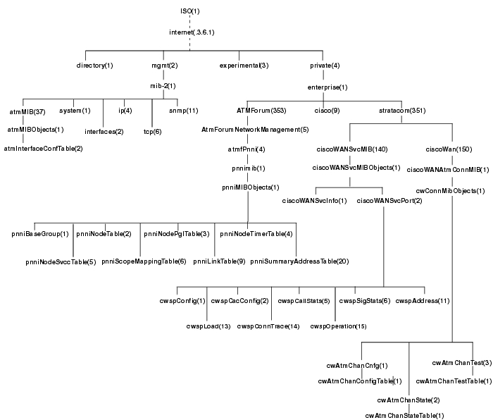

 Feedback