Cable and Connector Specifications
Available Languages
Table Of Contents
Cable and Connector Specifications
Console and Auxiliary Port Signals and Pinouts
Console Port Signals and Pinouts
Auxiliary Port Signals and Pinouts
MGX-RJ45-4E, -4E/B, and -FE Port Adapter Cable Pinouts
Fast Ethernet MII Port Adapter Pinouts
FDDI Optical Bypass Switch Pinouts (for RPM/B)
Cable and Connector Specifications
This appendix provides the following pinout information:
•
Console and Auxiliary Port Signals and Pinouts
•
•
•

Note
Note
Console and Auxiliary Port Signals and Pinouts
The RPM requires console and auxiliary cables so you can connect a console (an ASCII terminal or PC running terminal emulation software) or modem to your RPM. Cisco Systems does not provide these items. You will need the following items:
•
•
–
–
–
For console connections, proceed to the "Console Port Signals and Pinouts" section later in this appendix; for modem connections, proceed to the "Auxiliary Port Signals and Pinouts" section later in this appendix.
Identifying a Rollover Cable
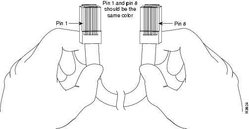
You can identify a rollover cable by comparing the two modular ends of the cable. Holding the cables side-by-side, with the tab at the back, the wire connected to the pin on the outside of the left plug should be the same color as the wire connected to the pin on the outside of the right plug (see Figure B-1). If your cable was purchased from Cisco Systems, pin 1 will be white on one connector, and pin 8 will be white on the other (a rollover cable reverses pins 1 and 8, 2 and 7, 3 and 6, and 4 and 5).
Figure B-1 Identifying a Rollover Cable
Console Port Signals and Pinouts
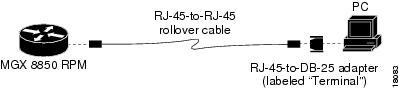
Use the thin, flat RJ-45-to-RJ-45 rollover cable and RJ-45-to-DB-9 female DTE adapter (labeled Terminal) to connect the console port to a PC running terminal emulation software. Figure B-2 shows how to connect the console port to a PC. Table B-1 lists the pinouts for the asynchronous serial console port, the RJ-45-to-RJ-45 rollover cable, and the RJ-45-to-DB-9 female DTE adapter (labeled Terminal).
Figure B-2 Connecting the Console Port to a PC
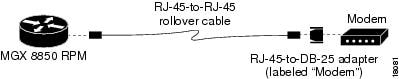
Table B-1 Console Port Signaling and Cabling Using a DB-9 Adapter
Terminal AdapterRTS
11
8
8
CTS
DTR
2
7
6
DSR
TxD
3
6
2
RxD
GND
4
5
5
GND
GND
5
4
5
GND
RxD
6
3
3
TxD
DSR
7
2
4
DTR
CTS
8
1
7
RTS
1 Pin 1 is connected internally to pin 8.
Note
Use the thin, flat RJ-45-to-RJ-45 rollover cable and RJ-45-to-DB-25 female DTE adapter (labeled Terminal) to connect the console port to a terminal. Figure B-3 shows how to connect the console port to a terminal. Table B-2 lists the pinouts for the asynchronous serial console port, the RJ-45-to-RJ-45 rollover cable, and the RJ-45-to-DB-25 female DTE adapter (labeled Terminal).
Figure B-3 Connecting the Console Port to a Terminal
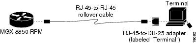
Table B-2 Console Port Signaling and Cabling Using a DB-25 Adapter
RTS
11
8
5
CTS
DTR
2
7
6
DSR
TxD
3
6
3
RxD
GND
4
5
7
GND
GND
5
4
7
GND
RxD
6
3
2
TxD
DSR
7
2
20
DTR
CTS
8
1
4
RTS
1 Pin 1 is connected internally to pin 8.
Note
Auxiliary Port Signals and Pinouts
Use the thin, flat RJ-45-to-RJ-45 rollover cable and RJ-45-to-DB-25 male DCE adapter (labeled Modem) to connect the auxiliary port to a modem. Figure B-4 shows how to connect the auxiliary port to a modem. Table B-3 lists the pinouts for the asynchronous serial auxiliary port, the RJ-45-to-RJ-45 rollover cable, and the RJ-45-to-DB-25 male DCE adapter (labeled Modem).
Figure B-4 Connecting the Auxiliary Port to a Modem
MGX-RJ45-4E, -4E/B, and -FE Port Adapter Cable Pinouts
Table B-4 provides pinouts for the 4E RJ-45 connector.
Note
Table B-4 4E or 4E/B RJ-45 Connector Pinout
1
Receive Data + (RxD+)
2
RxD-
3
Transmit Data + (TxD+)
6
TxD-
Note
Depending on your RJ-45 interface cabling requirements, use the pinouts in Figure B-5 and Figure B-6.
Figure B-5 Straight-Through Cable Pinout, 4E, 4E/B, or FE-TX RJ-45 Connection to a Hub or Repeater
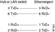
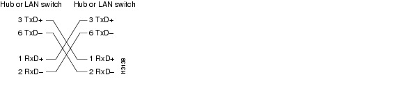
Figure B-6 Crossover Cable Pinout, 4E, 4E/B, or FE-TX RJ-45 Connections Between Hubs and Repeaters
Fast Ethernet MII Port Adapter Pinouts
Table B-5 provides pinouts for the fast ethernet MII RJ-45 connector.
Table B-5 MII Connector Pinout
14-17
-
Yes
-
Transmit Data (TxD)
12
Yes
-
-
Transmit Clock (Tx_CLK)2
11
-
Yes
-
Transmit Error (Tx_ER)
13
-
Yes
-
Transmit Enable (Tx_EN)
3
-
Yes
-
MII Data Clock (MDC)
4-7
Yes
-
-
Receive Data (RxD)
9
Yes
-
-
Receive Clock (Rx_CLK)
10
Yes
-
-
Receive Error (Rx_ER)
8
Yes
-
-
Receive Data Valid (Rx_DV)
18
Yes
-
-
Collision (COL)
19
Yes
-
-
Carrier Sense (CRS)
2
-
-
Yes
MII Data Input/Output (MDIO)
22-39
-
-
-
Common (ground)
1, 20, 21, 40
-
-
-
+5.0 volts (V)
1 Any pins not indicated are not used.
2 Tx_CLK and Rx_CLK are generated by the external transceiver.
FDDI Optical Bypass Switch Pinouts (for RPM/B)
Table B-6 lists the signal descriptions for the mini-DIN optical bypass switch available on the FDDI port adapters. The mini-DIN-to-DIN adapter cable (CAB-FMDD=) allows a connection to an optical bypass switch with a DIN connector (which is larger than the mini-DIN connector on the FDDI port adapters).
Note
 Feedback
Contact Cisco
- Open a Support Case

- (Requires a Cisco Service Contract)