Configuring Ethernet CFM, E-LMI, and OAM
Available Languages
Table Of Contents
Configuring Ethernet CFM, E-LMI and OAM
Default Ethernet CFM Configuration
Ethernet CFM Configuration Guidelines
Preparing the Ethernet CFM Network
Configuring Ethernet CFM Service
Configuring Ethernet CFM Crosscheck
Displaying Ethernet CFM Information
Understanding E-LMI and Interactions with CFM
E-LMI Interaction with OAM Manager
CFM Interaction with OAM Manager
Configuring E-LMI Interaction with CFM
Default E-LMI and OAM Configuration
E-LMI and OAM Configuration Guidelines
Configuring OAM Manager on a Provider-Edge Switch
Ethernet OAM Manager Configuration Example
Provider-Edge Device Configuration
Customer-Edge Device Configuration
Displaying E-LMI and OAM Manager Information
Understanding the Ethernet OAM Protocol
Setting Up and Configuring Ethernet OAM
Default Ethernet OAM Configuration
Ethernet OAM Configuration Guidelines
Enabling Ethernet OAM on an Interface
Enabling Ethernet OAM Remote Loopback
Configuring Ethernet OAM Link Monitoring
Configuring Ethernet OAM Remote Failure Indications
Configuring Ethernet OAM Templates
Displaying Ethernet OAM Protocol Information
Configuring Ethernet CFM, E-LMI and OAM
Ethernet Operations, Administration, and Maintenance (OAM) is a protocol for installing, monitoring, and troubleshooting Ethernet networks. Metro Ethernet service providers in particular require certain management capability within the context of the overall Ethernet infrastructure. In Cisco IOS Release 12.2(25)SEG, support was added for IEEE 802.1ag Connectivity Fault Management (CFM) and Ethernet Local Management Interface (E-LMI). Ethernet OAM manager controls the interworking between CFM and E-LMI. Beginning with Cisco IOS Release 12.2(35)SE, the Catalyst 3750 Metro switch also supports IEEE 802.3ah Ethernet OAM discovery, link monitoring, remote fault detection, and remote loopback. This chapter provides general information about configuring CFM, E-LMI, and the Ethernet OAM protocol.
For complete command and configuration information for CFM, see the Cisco IOS feature module at this URL
http://www.cisco.com/en/US/products/ps6922/products_feature_guide09186a008066fcb8.htmlFor E-LMI configuration and commands see this URL: http://www.cisco.com/en/US/products/ps6441/products_feature_guide09186a0080690f2d.html
For complete syntax of the Ethernet OAM manager commands used in this chapter to configure CFM and E-LMI interaction, see the command reference for this release.
For complete command and configuration for the Ethernet OAM protocol, see the Cisco IOS feature module at this URL:
http://www.cisco.com/en/US/products/ps6922/products_feature_guide09186a008067344c.htmlFor documentation for the CFM and Ethernet OAM commands, see this URL:
http://www.cisco.com/en/US/products/ps6922/products_command_reference_book09186a0080699104.htmlThis chapter consists of these sections:
•
Displaying Ethernet CFM Information
•
•
•
•
•
•
Understanding Ethernet CFM
Ethernet CFM is an end-to-end per-service-instance (per VLAN) Ethernet layer OAM protocol that includes proactive connectivity monitoring, fault verification, and fault isolation. End-to-end can be provider-edge-to provider-edge (PE-to-PE) device or customer-edge-to-customer-edge (CE-to-CE) device. Ethernet CFM, as specified by IEEE 802.1ag, is the standard for Layer 2 ping, Layer 2 traceroute, and end-to-end connectivity check of the Ethernet network.

Note
These sections contain this conceptual information about Ethernet CFM:
CFM Domain
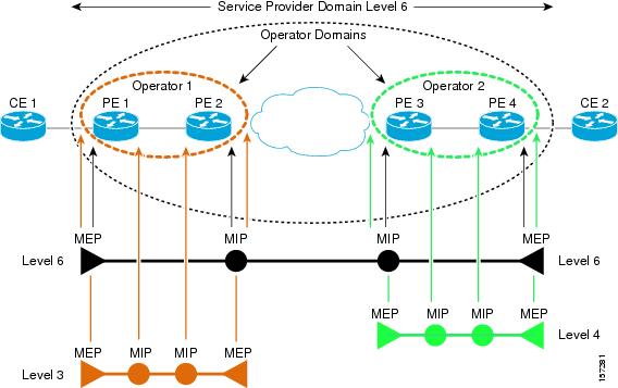
A CFM maintenance domain is a management space on a network that is owned and operated by a single entity and defined by a set of ports internal to it, but at its boundary. The network administrator assigns a unique maintenance level (from 0 to 7) to define the hierarchical relationship between domains. The larger the domain, the higher the level. For example, as shown in Figure 37-1, a service-provider domain would be larger than an operator domain and might have a maintenance level of 6, while the operator domain maintenance level is 3 or 4.
Figure 37-1 CFM Maintenance Domains
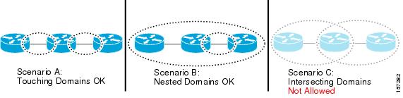
As shown in Figure 37-2, domains cannot intersect or overlap because that would require management by more than one entity, which is not allowed. Domains can touch or nest (if the outer domain has a higher maintenance level than the nested domain). Nesting domains is useful when a service provider contract with one or more operators to provide Ethernet service. Each operator has its own maintenance domain and the service provider domain is a superset of the operator domains. Maintenance levels of nesting domains should be communicated among the administrating organizations. CFM exchanges messages and performs operations on a per-domain basis.
Figure 37-2 Allowed Domain Relationships
Maintenance Points
A maintenance point is a demarcation point on an interface that participates in CFM within a maintenance domain. Maintenance points drop all lower-level frames and forward all higher-level frames. There are two types of maintenance points:
•
•
If port on which the MEP is configured is blocked by Spanning-Tree Protocol (STP), the port cannot receive or transmit CFM messages. If a port on which a MIP is configured is blocked by STP, the port cannot receive or respond to messages from the relay function side, but can receive and respond to CFM messages from the wire side.
CFM Messages
CFM uses standard Ethernet frames distinguished by EtherType or (for multicast messages) by MAC address. All CFM messages are confined to a maintenance domain and to a service-provider VLAN (S-VLAN). These CFM messages are supported:
•
•
•
Crosscheck Function
The crosscheck function is a timer-driven post-provisioning service verification between dynamically configured MEPs (using crosscheck messages) and expected MEPs (by configuration) for a service. It verifies that all endpoints of a multipoint service are operational. The crosscheck function is performed only one time and is initiated from the command-line interface (CLI).
SNMP Traps
The MEPs generate two types of SMNP traps: CC traps and crosscheck traps. Supported CC traps are MEP up, MEP down, cross-connect (a service ID does not match the VLAN), loop, and configuration error. The crosscheck traps are service up, MEP missing (an expected MEP is down), and unknown MEP.
Configuring Ethernet CFM
Configuring Ethernet CFM requires preparing the network and configuring services. You can optionally configure and enable crosschecking. These sections are included
•
•
•
•
•
Default Ethernet CFM Configuration
CFM is globally disabled.
CFM is enabled on all interfaces. A port can be configured as a flow point (MIP/MEP), a transparent port, or disabled (CFM disabled). By default, ports are transparent ports until configured as a MEP, MIP, or disabled.
There are no MEPs or MIPs configured.
Ethernet CFM Configuration Guidelines
These are the configuration guidelines and restrictions for CFM:
•
•
•
•
Preparing the Ethernet CFM Network
Beginning in privileged EXEC mode, follow these steps to prepare the network for Ethernet CFM:
Use the no versions of the commands to remove the configuration or return to the default configurations.
Configuring Ethernet CFM Service
Beginning in privileged EXEC mode, follow these steps to set up service for Ethernet CFM:
Use the no form of each command to remove a configuration or to return to the default settings.
Configuring Ethernet CFM Crosscheck
Beginning in privileged EXEC mode, follow these steps to configure Ethernet CFM crosscheck:
Use the no form of each command to remove a configuration or to return to the default settings.
Displaying Ethernet CFM Information
You can use the privileged EXEC commands in Table 37-1 to display Ethernet CFM information.
Understanding E-LMI and Interactions with CFM
Ethernet Local Management Interface (E-LMI) is a protocol between the customer-edge (CE) device and the provider-edge (PE) device. It runs only on the PE-to-CE UNI link and notifies the CE device of connectivity status and configuration parameters of Ethernet services available on the CE port. E-LMI interoperates with an OAM protocol, such as CFM, that runs within the provider network to collect OAM status. CFM runs at the provider maintenance level (UPE to UPE with inward-facing MEPs at the UNI). E-LMI relies on the OAM Ethernet Infrastructure to interwork with CFM for end-to-end status of Ethernet virtual connections (EVCs) across CFM domains.
OAM manager streamlines interaction between OAM protocols, and handles the interaction between CFM and E-LMI. E-LMI interaction with OAM manager is unidirectional, running only from OAM manager to E-LMI on the UPE side of the switch. Information is exchanged either as a result of a request from E-LMI or triggered by OAM when it received notification of a change from the OAM protocol. This type of information is relayed:
•
•
•
You can configure Ethernet virtual connections (EVCs), service VLANs, UNI ids (for each CE-to-PE link), and UNI count and attributes. You need to configure CFM to notify the OAM manager of any change to the number of active UNIs and or the remote UNI ID for a given S-VLAN domain.
On previous releases, the E-LMI implementation on the Catalyst 3750 Metro switch included only provider-edge-side support. Beginning with Cisco IOS Release 12.2(37)SE, the Catalyst 3750 Metro switch can also be configured as the customer-edge device.
E-LMI Interaction with OAM Manager
No interactions are required between E-LMI and OAM manager on the CE side. On the UPE side, the OAM manager defines an abstraction layer that relays data collected from OAM protocols (in this case CFM) running within the metro network to the E-LMI switch. The information flow is unidirectional (from the OAM manager to the E-LMI) but is triggered in one of two ways:
•
•
This data includes:
•
•
•
The asynchronous update is triggered only when the number of active UNIs has changed.
CFM Interaction with OAM Manager
When there is a change in the number of active UNIs or remote UNI ID for a given S-VLAN or domain, CFM asynchronously notifies the OAM manager. A change in the number of UNIs might (or might not) cause a change in EVC status. OAM manager calculates EVC status given the number of active UNIs and the total number of associated UNIs.
Note
Configuring E-LMI Interaction with CFM
For E-LMI to work with CFM, you configure Ethernet virtual connections (EVCs), Ethernet service instances (EFPs), and E-LMI customer VLAN mapping. Most of the configuration occurs on the PE switch on the interfaces connected to the CE device. On the CE switch, you only need to enable E-LMI on the connecting interface. Note that you must configure some OAM parameters, for example, EVC definitions, on PE devices on both sides of a metro network.
This section includes this information:
•
•
•
Default E-LMI and OAM Configuration
Ethernet LMI is globally disabled by default. When enabled, the switch is in provider-edge (PE) mode by default.
When you globally enable E-LMI by entering the ethernet lmi global global configuration command, it is automatically enabled on all interfaces. You can also enable or disable E-LMI per interface to override the global configuration. The E-LMI command that is given last is the command that has precedence.
There are no EVCs, EFP service instances, or UNIs defined.
UNI bundling service is bundling with multiplexing.
E-LMI and OAM Configuration Guidelines
OAM manager is an infrastructural element and requires two interworking OAM protocols, in this case CFM and E-LMI. For OAM to operate, the PE side of the connection must be running CFM and E-LMI.
•
•
•
•
Configuring OAM Manager on a Provider-Edge Switch
Beginning in privileged EXEC mode, follow these steps to configure OAM manager on a PE switch:
Use the no forms of the commands to delete an EVC, EFP, or UNI ID, or to return to default configurations.
Note
Enabling E-LMI
You can enable E-LMI globally or on an interface and you can configure the switch as a PE or a CE device.
Beginning in privileged EXEC mode, follow these steps to enable for E-LMI on the switch or on an interface. Note that the order of the global and interface commands determines the configuration. The command that is entered last has precedence.
Use the no ethernet lmi global configuration command to globally disable E-LMI. Use the no form of the ethernet lmi interface configuration command with keywords to disable E-LMI on the interface or to return the timers to the default settings.
Use the show ethernet lmi commands to display information that was sent to the CE from the status request poll. Use the show ethernet service commands to show current status on the device.
Ethernet OAM Manager Configuration Example
This is a simple example of configuring CFM and E-LMI with OAM manager on a PE device and on a CE device. Beginning with Cisco IOS Release 12.2(37)SE, you can configure the Catalyst 3750 Metro switch as either the PE device or the CE device.
Provider-Edge Device Configuration
This example shows a sample configuration of OAM manager, CFM, and E-LMI on the PE device:
Switch# config tSwitch(config)# ethernet cfm domain Top level 7Switch(config)# ethernet cfm domain Provider level 4Switch(config-ether-cfm)# service customer_1 vlan 101Switch(config-ether-cfm)# mep crosscheck mpid 404 vlan 101Switch(config-ether-cfm)# exitSwitch(config)# ethernet cfm domain Operator_level 2Switch(config-ether-cfm)# service operator_1 vlan 101Switch(config-ether-cfm)# exitSwitch(config)# ethernet cfm enableSwitch(config)# ethernet evc test1Switch(config-evc)# oam protocol cfm svlan 101 domain ProviderSwitch(config-evc)# exitSwitch(config)# ethernet evc 101Switch(config-evc)# uni count 3Switch(config-evc)# oam protocol cfm svlan 101 domain OperatorSwitch(config-evc)# exitSwitch(config)# ethernet lmi globalSwitch(config)# interface gigabitethernet 1/0/2Switch(config-if)# service instance 101 ethernet test1Switch(config-if-srv)# ethernet lmi ce-vlan map 101Switch(config-if-srv)# exitSwitch(config-if)# exitSwitch(config)# ethernet cfm cc enable level 2-4 vlan 101Switch(config)# exitCustomer-Edge Device Configuration
This example shows the commands necessary to configure E-LMI on the CE device. Beginning with Cisco IOS Release 12.2(37)SE, the Catalyst 3750 Metro switch can be configured as the CE device.
This example enables E-LMI globally, but you can also enable it only on a specific interface. However, if you do not enter the ethernet lmi ce global configuration command, the interface will be in PE mode by default.
Switch# config tSwitch(config)# ethernet lmi globalSwitch(config)# ethernet lmi ceSwitch(config)# exit
Note
Displaying E-LMI and OAM Manager Information
You can use the privileged EXEC commands in Table 37-2 to display E-LMI or OAM manager information.
Understanding the Ethernet OAM Protocol
The Ethernet OAM protocol for installing, monitoring, and troubleshooting Metro Ethernet networks and Ethernet WANs relies on an optional sublayer in the data link layer of the OSI model. Normal link operation does not require Ethernet OAM. You can implement Ethernet OAM on any full-duplex point-to-point or emulated point-to-point Ethernet link for a network or part of a network (specified interfaces).
OAM frames, called OAM protocol data units (OAM PDUs) use the slow protocol destination MAC address 0180.c200.0002. They are intercepted by the MAC sublayer and cannot propagate beyond a single hop within an Ethernet network. Ethernet OAM is a relatively slow protocol, with a maximum transmission rate of 10 frames per second, resulting in minor impact to normal operations. However, when you enable link monitoring, because the CPU must poll error counters frequently, the number of required CPU cycles is proportional to the number of interfaces that must be polled.
Ethernet OAM has two major components:
•
•
–
–
–
OAM Features
These OAM features are defined by IEEE 802.3ah:
•
•
•
•
OAM Messages
Ethernet OAM messages or PDUs are standard length, untagged Ethernet frames between 64 and 1518 bytes. They do not go beyond a single hop and have a maximum transmission rate of 10 OAM PDUs per second. Message types are information, event notification, loopback control, or vendor-specific OAM PDUs.
Setting Up and Configuring Ethernet OAM
This section includes this information:
•
•
•
•
•
•
•
Default Ethernet OAM Configuration
Ethernet OAM is disabled on all interfaces.
When Ethernet OAM is enabled on an interface, link monitoring is automatically turned on.
Remote loopback is disabled.
No Ethernet OAM templates are configured.
Ethernet OAM Configuration Guidelines
Follow these guidelines when configuring Ethernet OAM:
•
•
•
Enabling Ethernet OAM on an Interface
Beginning in privileged EXEC mode, follow these steps to enable Ethernet OAM on an interface:
Enter the no ethernet oam interface configuration command to disable Ethernet OAM on the interface.
Enabling Ethernet OAM Remote Loopback
You must enable Ethernet OAM remote loopback on an interface for the local OAM client to initiate OAM remote loopback operations. Changing this setting causes the local OAM client to exchange configuration information with its remote peer. Remote loopback is disabled by default.
Remote loopback has these limitations:
•
•
•
Beginning in privileged EXEC mode, follow these steps to enable Ethernet OAM remote loopback on an interface:
Use the no ethernet oam remote-loopback {supported | timeout} interface configuration command to disable remote loopback support or remove the timeout setting.
Configuring Ethernet OAM Link Monitoring
You can configure high and low thresholds for link-monitoring features. If no high threshold is configured, the default is none —no high threshold is set. If you do not set a low threshold, it defaults to a value lower than the high threshold.
Beginning in privileged EXEC mode, follow these steps to configure Ethernet OAM link monitoring on an interface:
The ethernet oam link-monitor transmit-crc {threshold {high {high-frames | none} | low {low-frames}} | window milliseconds} command is visible on the switch and you are allowed to enter it, but it is not supported.Enter the no form of the commands to disable the configuration. Use the no form of each command to disable the threshold setting.
Configuring Ethernet OAM Remote Failure Indications
You can configure an error-disable action to occur on an interface if one of the high thresholds is exceeded, if the remote link goes down, if the remote device is rebooted, or if the remote device disables Ethernet OAM on the interface.
Beginning in privileged EXEC mode, follow these steps to enable Ethernet OAM remote-failure indication actions on an interface:
The Catalyst 3750 Metro switch does not generate Link Fault or Critical Event OAM PDUs. However, if these PDUs are received from a link partner, they are processed. The switch supports sending and receiving dying gasp OAM PDUs. Enter the no ethernet remote-failure {critical-event | dying-gasp | link-fault} action command to disable the remote failure indication action.
Configuring Ethernet OAM Templates
You can create a template for configuring a common set of options on multiple Ethernet OAM interfaces. The template can be configured to monitor frame errors, frame-period errors, frame-second errors, received CRS errors, and symbol-period errors and thresholds. You can also set the template to put the interface in error-disabled state if any high thresholds are exceeded. These steps are optional and can be performed in any sequence or repeated to configure different options.
Beginning in privileged EXEC mode, follow these steps to configure an Ethernet OAM template and to associate it with an interface:
The switch does not support monitoring egress frames with CRC errors. The ethernet oam link-monitor transmit-crc {threshold {high {high-frames | none} | low {low-frames}} | window milliseconds} command is visible on the switch and you can enter it, but it is not supported. Use the no form of each command to remove the option from the template. Use the no source-template template-name to remove the source template association.
Displaying Ethernet OAM Protocol Information
You can use the privileged EXEC commands in Table 37-3 to display Ethernet OAM protocol information.
 Feedback
Contact Cisco
- Open a Support Case

- (Requires a Cisco Service Contract)
This Document Applies to These Products
- Collaboration Endpoints - Retired Products
- Conferencing - Retired Products
- Contact Center - Retired Products
- Optical Networking - Retired Products
- Routers - Retired Products
- Security - Retired Products
- Servers - Unified Computing (UCS) Retired Products
- Storage Networking Retired Products
- Switches - Retired Products
- Video - Retired Products
- Wireless - Retired Products