FastHub 400 Series Cabling and Startup Quick Start Guide
Available Languages
Table Of Contents
Connect the Hub to Other Network Devices
Connect the Hub to Other Network Devices (continued)
(Optional) Assign IP Information to the Hub
(Optional) Display the FastHub 400 Series Hub Manager
Connect the Hub to Other Network Devices (continued)
Quick Start Guide
FastHub 400 10/100 Series
Cabling and Start UpConnect the Hub to Servers, Routers, and Workstations
Connect the Hub to Switches and Other Hubs
(Optional) Install the Switched Uplink Module in the Hub
(Optional) Connect to the Switched Uplink Module Port
(Optional) Connect the Console Cable
Quick Start Guide
FastHub 400 10/100 Series
Cabling and Start Up
If any item is missing or damaged, contact your Cisco representative or reseller for support.

Note:
You need to supply Category 3, 4, or 5 straight-through or crossover cables to connect to Ethernet devices.
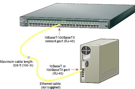
Note:
Connect the Hub to Servers, Routers, and Workstations
•
•
Connect the Hub to Switches and Other Hubs
•
•
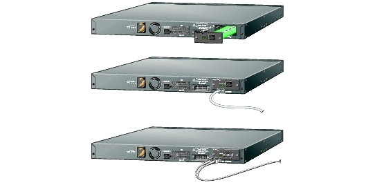
(Optional) Install the Switched Uplink Module in the Hub
1
2
3
4
5
6
7
(Optional) Connect to the Switched Uplink Module Port
Insert a connector according to the type of module (10/100 or 100BaseFX), as follows:
•
Note:
•

(Optional) Connect the Console Cable
1
1 stop bit, no parity, and no flow control.2
3
(if necessary, use an appropriate adapter, such as the supplied RJ-45-to-DB-9 adapter).4
Power Up the Hub
1
Note:
2
After POST completes, the Continue with configuration dialog? prompt appears on the management station. You can then follow the prompts to assign IP information to the hub.
The hub is designed to operate with little or no user intervention. In most cases, you can use it with its default settings.
Assign IP information to the FastHub 400M model so that you can use the FastHub 400 series Hub Manager web-based interface and so that the hub can communicate with local routers and the intranet.
Contact your system administrator for the hub IP information, and record it here.
Hub IP address:

Subnet mask:

Default gateway:

1
Continue with configuration dialog? Y2
Enter IP address: 10.1.105.203
(for example: 255.255.255.0):Enter IP netmask: 255.255.255.04
Enter IP default gateway: 10.1.105.254The following information is displayed:
The following configuration command
script was created:
ip address 10.1.105.20 255.255.255.0ip default-gateway 10.1.105.254!end5
Use this configuration? YThe following information is displayed:
Building configuration...Use the enabled mode `configuration' command to modify this configuration.Press RETURN to get started.6
7
You can now display the FastHub 400 series Hub Manager.
If you have the IP address to the hub, you can display the FastHub 400 series Hub Manager from your intranet. You can use the FastHub 400 series Hub Manager to configure and monitor the hub.
1
(4.01 or higher). Make sure that Java and JavaScript are enabled.2
(the Address field if you are using Internet Explorer).The FastHub 400 series Hub Manager Home page appears.

Note:
FastHub 400 10/100 series Hub Manager online help provide complete information about the web console and describe how to configure and monitor the hub.


 Feedback
Contact Cisco
- Open a Support Case

- (Requires a Cisco Service Contract)
This Document Applies to These Products
- Collaboration Endpoints - Retired Products
- Conferencing - Retired Products
- Contact Center - Retired Products
- Optical Networking - Retired Products
- Routers - Retired Products
- Security - Retired Products
- Servers - Unified Computing (UCS) Retired Products
- Storage Networking Retired Products
- Switches - Retired Products
- Video - Retired Products
- Wireless - Retired Products