Preparing for Installation
This section provides information about these topics:
Warnings
These warnings are translated into several languages in the Regulatory Compliance and Safety Information for this switch.
 Warning |
Before working on equipment that is connected to power lines, remove jewelry (including rings, necklaces, and watches). Metal objects will heat up when connected to power and ground and can cause serious burns or weld the metal object to the terminals. Statement 43 |
Warning |
Exposure to some chemicals could degrade the sealing properties of materials used in the sealed relay device. Statement 381 |
Warning |
Do not work on the system or connect or disconnect cables during periods of lightning activity. Statement 1001 |
Warning |
Before performing any of the following procedures, ensure that power is removed from the DC circuit. Statement 1003 |
Warning |
Read the installation instructions before you connect the system to its power source. Statement 1004 |
Warning |
This unit is intended for installation in restricted access areas. A restricted access area can be accessed only through the use of a special tool, lock and key, or other means of security. Statement 1017 |
Warning |
This equipment must be grounded. Never defeat the ground conductor or operate the equipment in the absence of a suitably installed ground conductor. Contact the appropriate electrical inspection authority or an electrician if you are uncertain that suitable grounding is available. Statement 1024 |
Warning |
This unit might have more than one power supply connection. All connections must be removed to de-energize the unit. Statement 1028 |
Warning |
Only trained and qualified personnel should be allowed to install, replace, or service this equipment. Statement 1030 |
Warning |
Ultimate disposal of this product should be handled according to all national laws and regulations. Statement 1040 |
Warning |
For connections outside the building where the equipment is installed, the following ports must be connected through an approved network termination unit with integral circuit protection. 10/100/1000 Ethernet Statement 1044 |
Warning |
To prevent the system from overheating, do not operate it in an area that exceeds the maximum recommended ambient temperature of: |
Warning |
158 F (70 C). For IE-4000-8GT8GP4G maximum recommend ambient is 131 F (55 C) at max POE budget of 240W. Statement 1047 |
Warning |
In switch installations in a hazardous location, the DC power source could be located away from the vicinity of the switch. Before performing any of the following procedures, locate the DC circuit to ensure that the power is removed and cannot be turned on accidentally, or verify that the area is nonhazardous before proceeding. Statement 1059 |
Warning |
This equipment is supplied as “open type” equipment. It must be mounted within an enclosure that is suitably designed for those specific environmental conditions that will be present and appropriately designed to prevent personal injury resulting from accessibility to live parts. The interior of the enclosure must be accessible only by the use of a tool. |
Warning |
The enclosure must meet IP 54 or NEMA type 4 minimum enclosure rating standards. Statement 1063 |
Warning |
When used in a Class I, Division 2, hazardous location, this equipment must be mounted in a suitable enclosure with proper wiring method, for all power, input and output wiring, that complies with the governing electrical codes and in accordance with the authority having jurisdiction over Class I, Division 2 installations. Statement 1066 |
Warning |
Installation of the equipment must comply with local and national electrical codes. Statement 1074 |
Warning |
Explosion Hazard—The area must be known to be nonhazardous before installing, servicing, or replacing the unit. Statement 1082 |
Warning |
Explosion Hazard—Substitution of components may impair suitability for Class I, Division 2/Zone 2. Statement 1083 |
 Caution |
When installed in a Class I, Div/Zone 2 hazardous location environment, this equipment must be installed in a min. IP54, ATEX certified enclosure. |
Caution |
Airflow around the switch must be unrestricted. To prevent the switch from overheating, there must be the following minimum clearances: – Top and bottom: 2.0 in. (50.8 mm) – Sides: 2.0 in. (50.8 mm) – Front: 2.0 in. (50.8 mm) Contact your Cisco Technical Assistance Centre (TAC) if tighter spacings are required. |
Caution |
When installed in a Class I, Div/Zone 2 hazardous location environment, this equipment must be installed in a pollution degree 2 environment per IEC 60664-1) |
Caution |
This equipment is suitable for use in Class I, Division 2, Groups A, B, C, D, or only nonhazardous locations. |
Caution |
Airflow around the switch must be unrestricted. To prevent the switch from overheating, there must be the following minimum clearances: – Top and bottom: 2.0 in. (50.8 mm) – Sides: 2.0 in. (50.8 mm) – Front: 2.0 in. (50.8 mm) |
Environment and Enclosure Guidelines
Review these environmental and enclosure guidelines before installation:
-
This equipment is intended for use in a Pollution Degree 2 industrial environment, in overvoltage Category II applications (as defined in IEC publication 60664-1), at altitudes up to 9842 ft (3 km) without derating.
-
This equipment is considered Group 1, Class A industrial equipment, according to IEC/CISPR Publication 11. Without appropriate precautions, there may be potential difficulties ensuring electromagnetic compatibility in other environments due to conducted as well as radiated disturbance.
-
This equipment is supplied as open-type equipment. It must be mounted within an enclosure that is suitably designed for those specific environmental conditions that will be present and appropriately designed to prevent personal injury resulting from accessibility to live parts. The enclosure must have suitable flame-retardant properties to prevent or minimize the spread of flame, complying with a flame-spread rating of 5VA, V2, V1, V0 (or equivalent) if nonmetallic. The interior of the enclosure must be accessible only by the use of a tool. Subsequent sections of this publication might contain additional information regarding specific enclosure-type ratings that are required to comply with certain product safety certifications.
General Guidelines
Before installation, observe these general guidelines:
Caution |
Proper ESD protection is required whenever you handle Cisco equipment. Installation and maintenance personnel should be properly grounded by using ground straps to eliminate the risk of ESD damage to the switch. |
Do not touch connectors or pins on component boards. Do not touch circuit components inside the switch. When not in use, store the equipment in appropriate static-safe packaging.
-
The switch only meets the requirements of IEC 61850-3 when powered by a redundant power supply configuration.
-
If you are responsible for the application of safety-related programmable electronic systems (PES), you need to be aware of the safety requirements in the application of the system and be trained in using the system.
Caution |
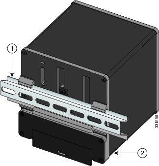
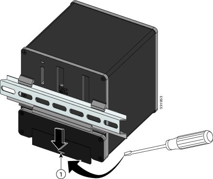
The device is designed to mount on a DIN rail that conforms to Standard EN50022. |
When determining where to place the switch, observe these guidelines:
-
Before installing the switch, first verify that the switch is operational by powering it on and observing boot fast. Follow the procedures in the Verifying Switch Operation, page 39.
-
For 10/100 ports and 10/100/1000 ports, the cable length from a switch to an attached device cannot exceed 328 feet (100 meters).
-
For 100BASE-FX fiber-optic ports, the cable length from a switch to an attached device cannot exceed 6562 ft (2 km).
-
Clearance to front and rear panels meets these conditions:
-
Front-panel LEDs can be easily read.
-
Access to ports is sufficient for unrestricted cabling.
-
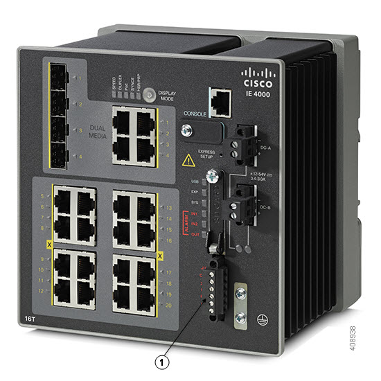
Front-panel direct current (DC) power connectors and the alarm connector are within reach of the connection to the DC power source.
-
-
Airflow around the switch must be unrestricted. To prevent the switch from overheating, you must have the following minimum clearances:
-
Top and bottom: 2.0 in. (50.8 mm)
-
Sides: 2.0 in. (50.8 mm)
-
Front: 2.0 in. (50.8 mm)
-
Caution |
When the switch is installed in an industrial enclosure, the temperature within the enclosure is greater than normal room temperature outside the enclosure. |
Ensure temperatures inside the enclosure conform to device specifications detailed in Table 5 on page 67.
-
Cabling is away from sources of electrical noise, such as radios, power lines, and fluorescent lighting fixtures.
Verifying Package Contents
If any item is missing or damaged, contact your Cisco representative or reseller for support.


 Feedback