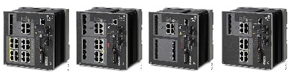
Product Overview

This chapter contains the following sections:

Switch Models

Model

Description

IE-4000-4TC4G-E

4 FE Combo DL ports, 4 GE combo UL ports, w/FPGA

IE-4000-8T4G-E

8 FE Copper DL ports, 4 GE combo UL ports, w/FPGA

IE-4000-8S4G-E

8 FE Fiber DL ports, 4 GE combo UL ports, w/FPGA

IE-4000-4T4P4G-E

4 FE Copper DL ports + 4 FE Copper DL ports with POE1, 4 GE combo UL ports, w/FPGA

IE-4000-16T4G-E

16 FE Copper DL ports, 4 GE combo UL ports, w/FPGA

IE-4000-4S8P4G-E

4 FE Fiber DL ports + 8 FE Copper DL ports with POE1, 4 GE combo UL ports, w/FPGA

IE-4000-8GT4G-E

8 GE Copper DL ports, 4 GE combo UL ports, w/FPGA

IE-4000-8GS4G-E

8 GE Fiber DL ports, 4 GE combo UL ports, w/FPGA

IE-4000-4GC4GP4G-E

4 GE Combo DL ports + 4 GE Copper DL ports with POE1, 4 GE combo UL ports, w/FPGA

IE-4000-16GT4G-E

16 GE Copper DL ports, 4 GE combo UL ports, w/FPGA

IE-4000-8GT8GP4G-E

8 GE Copper DL ports + 8 GE Copper DL ports with POE1, 4 GE combo UL ports, w/FPGA

IE-4000-4GS8GP4G-E

4 GE Fiber DL ports + 8 GE Copper DL ports with POE1, 4 GE combo UL ports, w/FPGA


Note


1 - IE-4000-8GT8GP4G-E supports up to 240W PoE, consisting of eight ports of PoE+ (30 W per port; IEEE 802.3at) with temperature derating (131°F (55°C) at full 240W PoE power) and depending on the power source used. All other PoE-capable models support up to 120W PoE, either PoE (15.4 W per port; IEEE 802.3af) or PoE+ (30 W per port; IEEE 802.3at) over the full operating temperature range.

Front Panel Overview

The illustrations in this section provide an overview of the variety of components available on the various switch models in this product family. Not all models are illustrated.

Figure 1. Cisco IE-4000-8GT8GP4G-E shown

1

SFP module slots (uplink ports)

6

Power connector DC-B

2

10/100/1000 Ethernet ports (downlink ports)

7

Power connector DC-A

3

Flash memory card slot

8

RJ-45 console port

4

Alarm connector

9

USB mini-Type B (console) port1

5

Protective ground connection

10

Dual-purpose ports (uplink ports)

  1. Use a screwdriver to remove the port cover and access the port.

Ports and Slots


Note


Different configurations are available. Not all ports or slots are present in all configurations.

10/100/1000 BASE-T Downlink Ports

You can set the 10/100BASE-T downlink ports to operate at 10 or 100 Mb/s in full-duplex or half-duplex mode. You can also set these ports for speed and duplex autonegotiation in compliance with IEEE 802.3AB. (The default setting is autonegotiate.) When set for autonegotiation, the port senses the speed and duplex settings of the attached device and advertises its own capabilities. If the connected device also supports autonegotiation, the switch port negotiates the best connection (that is, the fastest line speed that both devices support, and full-duplex transmission if the attached device supports it) and configures itself accordingly. In all cases, the attached device must be within 328 feet (100 meters). 100BASE-TX traffic requires Category 5 cable. 10BASE-T traffic can use Category 3 or Category 4 cables.

When connecting the switch to workstations, servers, routers, and Cisco IP phones, make sure that the cable is a straight-through cable.

You can use the mdix auto interface configuration command in the command-line interface (CLI) to enable the automatic medium-dependent interface crossover (auto-MDIX) feature. When the auto-MDIX feature is enabled, the switch detects the required cable type for copper Ethernet connections and configures the interfaces accordingly. For configuration information for this feature, see the switch software configuration guide or the switch command reference.

10/100/1000BASE-T Uplink Ports

The IEEE 802.3u 10/100/1000BASE-T uplink ports provide full-duplex 10, 100 or 1000 Mb/s connectivity over Category 5 unshielded twisted pair (UTP) copper cabling. The default setting is autonegotiate. The cable can be up to 100 m (0.1 km) in length.

100/1000 Mb/s SFP Module Downlink Slots

The IEEE 802.3u 100 Mb/s SFP module downlink slots provide full-duplex 100 Mb/s connectivity over multi-mode (MM) fiber cables or single-mode (SM) fiber cables. These ports use a SFP fiber-optic transceiver module that accepts a dual LC connector. Check the SFP specifications for the cable type and length.

100/1000 Mb/s SFP Module Uplink Slots

The IEEE 802.3u 100 Mb/s SFP module uplink slots provide full-duplex 100 or 1000 Mb/s connectivity over multi-mode (MM) fiber cables or single-mode (SM) fiber cables. These ports use a SFP fiber-optic transceiver module that accepts a dual LC connector. Check the SFP specifications for the cable type and length.

Management Ports

You can connect the switch to a PC running Microsoft Windows or to a terminal server through either the RJ-45 console port or the USB mini-Type B console port, also referred to as the USB-mini console port. These ports use the following connectors:

  • RJ-45 console port uses an RJ-45-to-DB-9 female cable.

  • USB-mini console port (5-pin connector) uses a USB Type A-to-5-pin mini-Type B cable.

The USB-mini console interface speeds are the same as the RJ-45 console interface speeds.

To use the USB-mini console port, you must install the Cisco Windows USB device driver on the device that is connected to the USB-mini console port and that is running Microsoft Windows.

Note: For information about downloading the Cisco USB device driver, see Installing the Cisco Microsoft Windows XP, 2000, Vista, 7, 8, and 10 USB Device Driver.

With the Cisco Windows USB device driver, connecting and disconnecting the USB cable from the console port does not affect Windows HyperTerminal operations. Mac OS X or Linux require no special drivers.

Note: The 5-pin mini-Type B connectors resemble the 4-pin mini-Type B connectors, but they are not compatible. Use only the 5-pin mini-Type B.

Figure 2. USB Mini-Type B Port

The configurable inactivity timeout reactivates the RJ-45 console port if the USB-mini console port is activated, but no input activity occurs for a specified time period. When the USB-mini console port deactivates due to a timeout, you can restore its operation by disconnecting and reconnecting the USB cable. For information on using the CLI to configure the USB-mini console interface, see the switch software guide.

DC Power Connector

You connect the DC power to the switch through the front panel connectors. The switch has a dual-feed DC power supply; two connectors provide primary and secondary DC power (DC-A and DC-B). The DC power connectors are near the top right of the front panel. Each power connector has an LED status indicator.

The switch power connectors are attached to the switch chassis. Each power connector has screw terminals for terminating the DC power. All connectors are attached to the switch front panel with the provided captive screws.

The power connector labeling is on the panel. The positive DC power connection is labeled “ +”, and the return connection is labeled “ –”.

The switch can operate with a single power source or with dual power sources. When both power sources are operational, the switch draws power from the DC source with the higher voltage. If one of the two power sources fail, the other continues to power the switch.

Alarm Connector

You connect the alarm signals to the switch through the alarm connector. The switch supports two alarm inputs and one alarm output relay. The alarm connector is on the bottom right of the front panel. See the following figure.

The alarm connector provides six alarm wire connections. The connector is attached to the switch front panel with the provided captive screws.

Figure 3. Alarm Connector

Both alarm input circuits can sense if the alarm input is open or closed. The alarm inputs can be activated for environmental, power supply, and port status alarm conditions. From the CLI, you can configure each alarm input as an open or closed contact.

The alarm output circuit is a relay with a normally open and a normally closed contact. The switch is configured to detect faults that are used to energize the relay coil and change the state on both of the relay contacts: normally open contacts close, and normally closed contacts open. The alarm output relay can be used to control an external alarm device, such as a bell or a light.

See the switch software configuration guide for instructions on configuring the alarm relays.

For more information about the alarm connector, see Cables and Connectors.

SFP Modules Supported

The SFP modules are switch Ethernet SFP modules that provide connections to other devices. Depending on the switch model, these field-replaceable transceiver modules provide uplink or downlink interfaces. The modules have LC connectors for fiber-optic connections.

Refer to the IE4000 Data Sheet for details about the supported SFP Modules.

LEDs

You can use the LEDs to monitor the switch status, activity, and performance. The following figure shows the front panel LEDs.

Figure 4. LEDs on the Cisco IE 4000 Switch

1

Dual Media port LEDs

9

USB mini-Type B (console) port LED

2

SFP module slot LEDs

10

Display Mode Switch

3

10/100/1000 BASE-T downlink port LEDs

11

HSR/PRP

4

Alarm LEDs

12

SYNCE LED

5

Power connector DC-A LED

13

POE port status LED

6

Power connector DC-B LED

14

Duplex LED

7

System LED

15

Speed

8

Express Setup LED

Display Mode Switch

The Display Mode Switch allows you to choose the mode you want displayed by the port LEDs. The LEDs to the left of the switch indicate the chosen display mode. Each time you press the switch, the mode indicator will move from Speed, Duplex, PoE, Synce, and HSR/PRP respectively.

Express Setup LED

The Express Setup LED displays the express setup mode for the initial configuration.

Color

Setup Status

Off (dark)

Switch is configured as a managed switch.

Solid green

Switch is operating normally.

Blinking green

Switch is in initial setup, in recovery, or initial setup is incomplete.

Solid red

Switch failed to start initial setup or recovery because there is no available switch port to which to connect the management station. Disconnect a device from a switch port, and then press the Express Setup button.

System LED

The System LED shows whether the system is receiving power and is functioning properly.

Color

Setup Status

Off

System is not powered on.

Blinking green

Boot fast is in progress.

Green

System is operating normally.

Red

Switch is not functioning properly.

USB-Mini Console LED

The USB-mini console LED shows which console port is in use. See LEDs for the LED location. If you connect a cable to a console port, the switch automatically uses that port for console communication. If you connect two console cables, the USB-mini console port has priority.

Color

Description

Green

USB-mini console port is active.

RJ-45 console port LED is not active.

Off

Port is not active.

RJ-45 console port is active.

Alarm LEDs

Alarm OUT

Color

System Status

Off

Alarm OUT is not configured, or the switch is off.

Green

Alarm OUT is configured, no alarm detected.

Blinking red

Switch has detected a major alarm.

Red

Switch has detected a minor alarm.

Alarm IN1 and IN2

Color

System Status

Off

Alarm IN1 or IN2 not configured.

Green

Alarm IN1 or IN2 configured, no alarm detected.

Blinking red

Major alarm detected.

Red

Minor alarm detected.

Power Status LEDs

The switch can operate with one or two DC power sources. Each DC input has an associated LED that shows the status of the corresponding DC input. If power is present on the circuit, the LED is green. If power is not present, the LED color depends on the alarm configuration. If alarms are configured, the LED is red when power is not present; otherwise, the LED is off.

If the switch has dual power sources, the switch draws power from the power source with the higher voltage. If one of the DC sources fails, the alternate DC source powers the switch, and the corresponding power status LED is green. The power status for the failed DC source is either off or red, depending on the alarm configuration.

Color

System Status

Green

Power is present on the associated circuit, system is operating normally.

Off

Power is not present on the circuit, or the system is not powered up.

Red

Power is not present on the associated circuit, and the power supply alarm is configured.

The Power A and Power B LEDs show that power is not present on the switch if the power input drops below the low valid level. The power status LEDs only show that power is present if the voltage at the switch input exceeds the valid level.

For information about the power LED colors during the boot fast sequence, see Verifying Switch Operation.

Port Status LEDs

Color

System Status

Green

No link.

Off

Link present.

Red

Activity. Port is sending or receiving data.

Alternating green-amber

Link fault. Error frames can affect connectivity, and errors such as excessive collisions, CRC errors, and alignment and jabber errors are monitored for a link-fault indication.

Solid amber

Port is not forwarding. The port was disabled by management, an address violation, or STP.

After a port is reconfigured, the port LED can remain amber for up to 30 seconds while STP checks the switch for possible loops.

Dual-Purpose Port LEDs

The Dual Purpose LEDs show how the port is being used (Ethernet or SFP module). The LED colors have the same meanings as for the Port Status LEDs.

PoE Status LED

The PoE STATUS LEDs are located on the front panel, next to the PoE ports (models equipped with PoE ports).The LEDs display the functionality and status of the adjacent PoE ports.

Table 1.

Color

PoE Status

Off

PoE is off. If the powered device is receiving power from a non-PoE power source, the port LED is off even if the powered device is connected to the switch port.

Green

PoE is on. The port LED is green only when the PoE port is providing power.

Alternating green and amber

PoE is denied because providing power to the powered device will exceed the switch power capacity.

Flashing amber

PoE is off due to a fault.

Caution: Noncompliant cabling or powered devices can cause a PoE port fault. Use only standard-compliant cabling to connect Cisco pre-standard IP Phones and wireless access points or IEEE 802.3af-compliant devices. You must remove any cable or device that causes a PoE fault.

Amber

PoE for the port is disabled. (PoE is enabled by default.)

Flash Memory Card

The switch supports a flash memory card that makes it possible to replace a failed switch without reconfiguring the new switch. The slot for the flash memory card is on the front of the switch. The flash card is hot swappable and can be accessed on the front panel in non hazardous locations only. A cover protects the flash card and holds the card firmly in place. The cover is hinged and closed with a captive screw. This prevents the card from coming loose and protects against shock and vibration.

Note: For more information on inserting and removing the flash memory card, see Installing or Removing the Flash Memory Card (Optional).

Note: The replacement SD card part number is SD-IE-1GB.

Rear Panel

The rear panel of the switch has a latch for installation on a DIN rail. The latch is spring-loaded to move down to position the switch over a DIN rail and return to the original position to secure the switch to a DIN rail.

Figure 5. Cisco IE 4000 Switch Rear Panel

Management Options

The switch supports these management options:

  • Cisco Network Assistant

    Cisco Network Assistant is a PC-based network management GUI application optimized for LANs of small- and medium-sized businesses. Using the GUI, you can configure and manage switch clusters or standalone switches. Cisco Network Assistant is available at no cost and can be downloaded from this URL:

    http://www.cisco.com/en/US/products/ps5931/tsd_products_support_series_home.html

    For information on starting the Cisco Network Assistant application, see the Getting Started with Cisco Network Assistant guide on Cisco.com.

  • Device Manager

    You can use Device Manager, which is in the switch memory, to manage individual and standalone switches. This web interface offers quick configuration and monitoring. You can access Device Manager from anywhere in your network through a web browser. For more information, see the Device Manager online help.

  • Cisco IOS CLI

    The switch CLI is based on Cisco IOS software and is enhanced to support desktop-switching features. You can fully configure and monitor the switch. You can access the CLI either by connecting your management station directly to the switch management port, or a console port, or by using Telnet from a remote management station. See the switch command reference on Cisco.com for more information.

  • SNMP network management

    You can manage switches from a SNMP-compatible management station that is running platforms such as HP OpenView or SunNet Manager. The switch supports a comprehensive set of Management Information Base (MIB) extensions and four Remote Monitoring (RMON) groups. See the switch software configuration guide on Cisco.com and the documentation that came with your SNMP application for more information.

  • Common Industrial Protocol

    The Common Industrial Protocol (CIP) management objects are supported. The Cisco IE 4000 can be managed by CIP-based management tools, allowing the user to manage an entire industrial automation system with one tool.

  • PROFINET TCP/IP and RT

    This switch supports PROFINET TCP/IP and RT and can be managed by Siemens' automation software such as STEP 7.

Network Configurations

See the switch software configuration guideon Cisco.com for network configuration concepts and examples of using the switch to create dedicated network segments and interconnecting the segments through Gigabit Ethernet connections.