Connector Specifications
This section contains the following:
10/100/1000 Ports
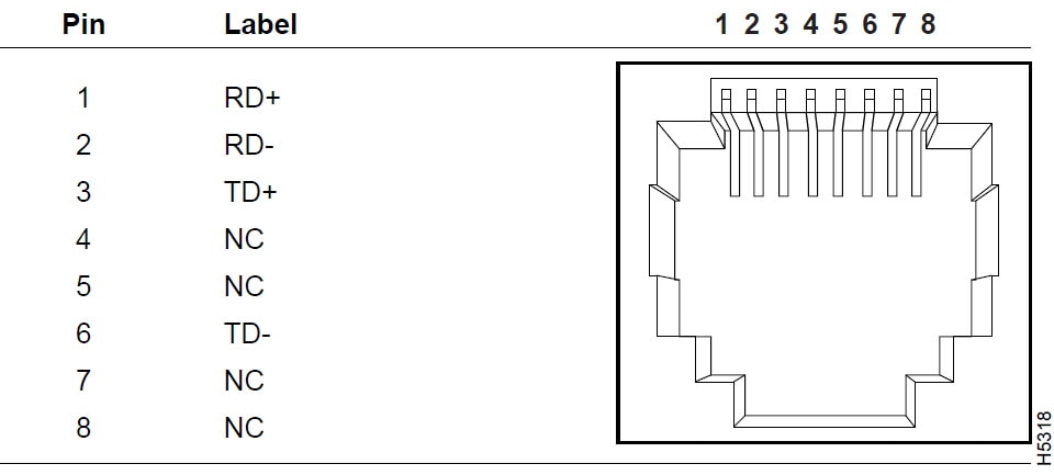
Note: For the three models of IE 4000 switch that support PoE, connector pins 4 and 5 supply +48 VDC and pins 7 and 8 are the DC voltage return lines.
SFP Module Connectors
The following figure shows a MT-RJ style connector that is used with the SFP Module slots. It is a fiber-optic cable connector.
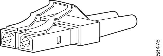
 Warning |
Invisible laser radiation may be emitted from disconnected fibers or connectors. Do not stare into beams or view directly with optical instruments. Statement 1051 |
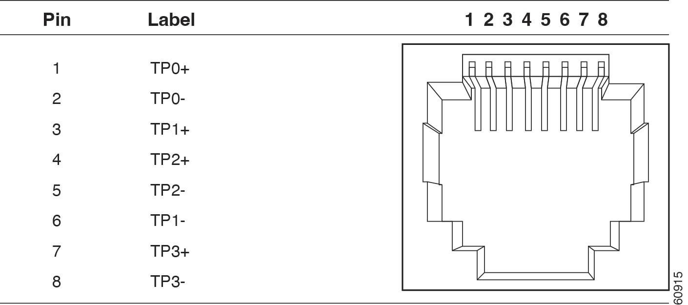
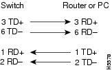
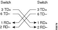
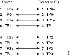
Dual-Purpose Ports
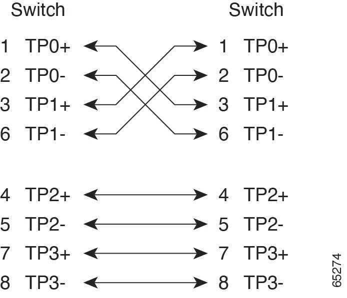
The 10/100/1000 Ethernet ports on the dual-purpose ports use RJ-45 connectors. The following figure shows the pinouts.
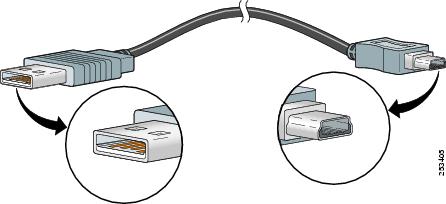
Console Port
The USB console port uses a USB Type A to 5-pin mini-Type B cable, shown in the following figure. The USB Type A-to-USB mini-Type B cable is not supplied. You can order an accessory kit (part number 800-33434) that contains this cable.
Note: When running Linux, access the USB Console using Minicom instead of Screen.
The RJ-45 console port uses an 8-pin RJ-45 connector The supplied RJ-45-to-DB-9 adapter cable is used to connect the console port of the switch to a console PC. You need to provide a RJ-45-to-DB-25 female DTE adapter if you want to connect the switch console port to a terminal. You can order a kit (part number ACS-DSBUASYN=) containing that adapter.
Alarm Port
The labels for the alarm connector pin-outs are on the switch panel and are displayed below.
|
Label |
Connection |
|---|---|
|
NO |
Alarm Output Normally Open (NO) connection |
|
COM |
Alarm Output Common connection |
|
NC |
Alarm Output Normally Closed (NC) connection |
|
IN2 |
Alarm Input 2 |
|
REF |
Alarm Input Reference Ground connection |
|
IN1 |
Alarm Input 1 |
 Feedback