Switch Installation
This chapter describes how to install your switch, verify the boot fast, and connect the switch to other devices. It also includes information specifically for installations in hazardous environments.
Read these topics, and perform the procedures in this order:
Preparing for Installation
This section provides information about these topics:
Installation Guidelines
When determining where to place the switch, observe these guidelines.
Environment and Enclosure Guidelines
Review these environmental and enclosure guidelines before installation:
■![]() This equipment is intended for use in a Pollution Degree 2 industrial environment, in overvoltage Category II applications (as defined in IEC publication 60664-1), at altitudes up to 9842 ft (3 km) without derating.
This equipment is intended for use in a Pollution Degree 2 industrial environment, in overvoltage Category II applications (as defined in IEC publication 60664-1), at altitudes up to 9842 ft (3 km) without derating.
■![]() This equipment is considered Group 1, Class A industrial equipment, according to IEC/CISPR Publication 11. Without appropriate precautions, there may be potential difficulties ensuring electromagnetic compatibility in other environments due to conducted as well as radiated disturbance.
This equipment is considered Group 1, Class A industrial equipment, according to IEC/CISPR Publication 11. Without appropriate precautions, there may be potential difficulties ensuring electromagnetic compatibility in other environments due to conducted as well as radiated disturbance.
■![]() This equipment is supplied as open-type equipment. It must be mounted within an enclosure that is suitably designed for those specific environmental conditions that will be present and appropriately designed to prevent personal injury resulting from accessibility to live parts. The enclosure must have suitable flame-retardant properties to prevent or minimize the spread of flame, complying with a flame-spread rating of 5VA, V2, V1, V0 (or equivalent) if nonmetallic. The interior of the enclosure must be accessible only by the use of a tool. Subsequent sections of this publication might contain additional information regarding specific enclosure-type ratings that are required to comply with certain product safety certifications.
This equipment is supplied as open-type equipment. It must be mounted within an enclosure that is suitably designed for those specific environmental conditions that will be present and appropriately designed to prevent personal injury resulting from accessibility to live parts. The enclosure must have suitable flame-retardant properties to prevent or minimize the spread of flame, complying with a flame-spread rating of 5VA, V2, V1, V0 (or equivalent) if nonmetallic. The interior of the enclosure must be accessible only by the use of a tool. Subsequent sections of this publication might contain additional information regarding specific enclosure-type ratings that are required to comply with certain product safety certifications.
General Guidelines
Before installation, observe these general guidelines:
Caution: Proper ESD protection is required whenever you handle Cisco equipment. Installation and maintenance personnel should be properly grounded by using ground straps to eliminate the risk of ESD damage to the switch.
Do not touch connectors or pins on component boards. Do not touch circuit components inside the switch. When not in use, store the equipment in appropriate static-safe packaging.
■![]() If you are responsible for the application of safety-related programmable electronic systems (PES), you need to be aware of the safety requirements in the application of the system and be trained in using the system.
If you are responsible for the application of safety-related programmable electronic systems (PES), you need to be aware of the safety requirements in the application of the system and be trained in using the system.
Caution: The device is designed to mount on a DIN rail that conforms to Standard EN50022.
When determining where to place the switch, observe these guidelines:
■![]() Before installing the switch, first verify that the switch is operational by powering it on and observing LEDs.
Before installing the switch, first verify that the switch is operational by powering it on and observing LEDs.
■![]() For 10/100 ports, the cable length from a switch to an attached device cannot exceed 328 feet (100 meters).
For 10/100 ports, the cable length from a switch to an attached device cannot exceed 328 feet (100 meters).
■![]() For 100BASE-FX fiber-optic ports, the cable length from a switch to an attached device cannot exceed 6562 ft (2 km).
For 100BASE-FX fiber-optic ports, the cable length from a switch to an attached device cannot exceed 6562 ft (2 km).
■![]() Clearance to front and rear panels meets these conditions:
Clearance to front and rear panels meets these conditions:
–![]() Front-panel LEDs can be easily read.
Front-panel LEDs can be easily read.
–![]() Access to ports is sufficient for unrestricted cabling.
Access to ports is sufficient for unrestricted cabling.
–![]() Front-panel direct current (DC) power connectors and the alarm connector are within reach of the connection to the DC power source.
Front-panel direct current (DC) power connectors and the alarm connector are within reach of the connection to the DC power source.
■![]() Airflow around the switch must be unrestricted. To prevent the switch from overheating, you must have the following minimum clearances:
Airflow around the switch must be unrestricted. To prevent the switch from overheating, you must have the following minimum clearances:
–![]() Top and bottom: 2.0 in. (50.8 mm)
Top and bottom: 2.0 in. (50.8 mm)
Caution: When the switch is installed in an industrial enclosure, the temperature within the enclosure is greater than normal room temperature outside the enclosure.
Ensure temperatures inside the enclosure conform to device specifications detailed in Table 1.
■![]() Cabling is away from sources of electrical noise, such as radios, power lines, and fluorescent lighting fixtures.
Cabling is away from sources of electrical noise, such as radios, power lines, and fluorescent lighting fixtures.
Connecting to Power
Tools and Equipment
Obtain these necessary tools and equipment:
■![]() Ratcheting torque flathead screwdriver that exerts up to 18 in-lb (2.03 N-m) of pressure.
Ratcheting torque flathead screwdriver that exerts up to 18 in-lb (2.03 N-m) of pressure.
■![]() For the protective ground connector, obtain a single or pair of stu size 6 ring terminals (such as Hollingsworth part number R3456B or equivalent).
For the protective ground connector, obtain a single or pair of stu size 6 ring terminals (such as Hollingsworth part number R3456B or equivalent).
■![]() Crimping tool (such as Thomas & Bett part number WT4000, ERG-2001, or equivalent).
Crimping tool (such as Thomas & Bett part number WT4000, ERG-2001, or equivalent).
■![]() For DC power connections, use UL- and CSA-rated, style 1007 or 1569 twisted-pair copper appliance wiring material (AWM) wire.
For DC power connections, use UL- and CSA-rated, style 1007 or 1569 twisted-pair copper appliance wiring material (AWM) wire.
■![]() Wire-stripping tools for stripping 10- and 18-gauge wires.
Wire-stripping tools for stripping 10- and 18-gauge wires.
Supported Power Supplies
Installing the Power Supply on a DIN Rail, Wall, or Rack Adapter
You install the power converter on a DIN rail, wall, or rack as you would a switch module.
Warning: This equipment is supplied as “open type” equipment. It must be mounted within an enclosure that is suitably designed for those specific environmental conditions that will be present and appropriately designed to prevent personal injury resulting from accessibility to live parts. The interior of the enclosure must be accessible only by the use of a tool.
The enclosure must meet IP 54 or NEMA type 4 minimum enclosure rating standards. Statement 1063
Caution: To prevent the switch assemble from overheating, there must be sufficient spacings as explained under Installation Guidelines, between any other switch assembly.
Grounding the Switch
Make sure to follow any grounding requirements at your site.
Warning: This equipment must be grounded. Never defeat the ground conductor or operate the equipment in the absence of a suitably installed ground conductor. Contact the appropriate electrical inspection authority or an electrician if you are uncertain that suitable grounding is available. Statement 1024
Warning: This equipment is intended to be grounded to comply with emission and immunity requirements. Ensure that the switch functional ground lug is connected to earth ground during normal use. Statement 1064
Caution: To make sure that the equipment is reliably connected to earth ground, follow the grounding procedure instructions, and use a UL-listed ring terminal lug suitable for number 10-to-12 AWG wire, such as Hollingsworth part number R3456B or equivalent)
Caution: Use at least a 4 mm2 (0.006 in2) conductor to connect to the external grounding screw.
The ground lug is not supplied with the switch. You can use one of the these options:
To ground the switch to earth ground by using the ground screw, follow these steps:
1.![]() Use a standard Phillips screwdriver or a ratcheting torque screwdriver with a Phillips head to remove the ground screw from the front panel of the switch. Store the ground screw for later use.
Use a standard Phillips screwdriver or a ratcheting torque screwdriver with a Phillips head to remove the ground screw from the front panel of the switch. Store the ground screw for later use.
2.![]() Use the manufacturer’s guidelines to determine the wire length to be stripped.
Use the manufacturer’s guidelines to determine the wire length to be stripped.
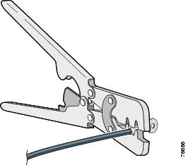
3.![]() Insert the ground wire into the ring terminal lug, and using a crimping tool, crimp the terminal to the wire. See Figure 5. If two ring terminals are being used, repeat this action for a second ring terminal.
Insert the ground wire into the ring terminal lug, and using a crimping tool, crimp the terminal to the wire. See Figure 5. If two ring terminals are being used, repeat this action for a second ring terminal.
Figure 5 Crimping the Ring Terminal
4.![]() Slide the ground screw through the terminal.
Slide the ground screw through the terminal.
5.![]() Insert the ground screw into the functional ground screw opening on the front panel.
Insert the ground screw into the functional ground screw opening on the front panel.
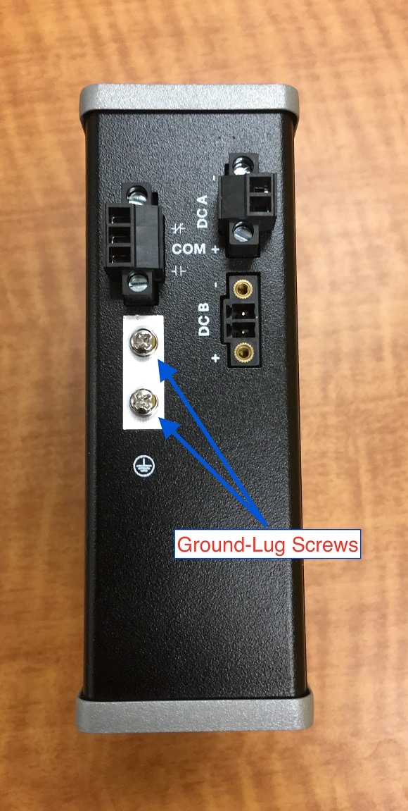
6.![]() Use a ratcheting torque screwdriver to tighten the ground screws and ring terminal to the switch top panel. The torque should not exceed 4.5 in-lb (0.51 N-m). See Figure 6.
Use a ratcheting torque screwdriver to tighten the ground screws and ring terminal to the switch top panel. The torque should not exceed 4.5 in-lb (0.51 N-m). See Figure 6.
7.![]() Attach the other end of the ground wire to a grounded bare metal surface, such as a ground bus, a grounded DIN rail, or a grounded bare rack.
Attach the other end of the ground wire to a grounded bare metal surface, such as a ground bus, a grounded DIN rail, or a grounded bare rack.
Connecting the Power Supply to a DC Power Source
You can also connect the power converter to a DC power source. Several power supplies can be used. Refer to Supported Power Supplies for the appropriate DC input ratings.
Note: Use copper conductors only, rated at a minimum temperature of 167°F (75°C).
Warning: Use twisted-pair supply wires suitable for 86°F (30°C) above surrounding ambient temperature outside the enclosure. Statement 1067
1.![]() Measure a single length of stranded copper wire long enough to connect the power converter to the earth ground. The wire color might differ depending on the country that you are using it in.
Measure a single length of stranded copper wire long enough to connect the power converter to the earth ground. The wire color might differ depending on the country that you are using it in.
For connections from the power converter to earth ground, use shielded 14-AWG stranded copper wire.
2.![]() Measure a length of twisted-pair copper wire long enough to connect the power converter to the DC power source.
Measure a length of twisted-pair copper wire long enough to connect the power converter to the DC power source.
For DC connections from the power converter to the DC source, use 10-AWG twisted-pair copper wire.
3.![]() Using a 14-gauge wire-stripping tool, strip the ground wire and both ends of the twisted pair wires to 0.25 inch (6.3 mm) ± 0.02 inch (0.5 mm). Do not strip more than 0.27 inch (6.8 mm) of insulation from the wires. Stripping more than the recommended amount of wire can leave exposed wire from the power and relay connector after installation.
Using a 14-gauge wire-stripping tool, strip the ground wire and both ends of the twisted pair wires to 0.25 inch (6.3 mm) ± 0.02 inch (0.5 mm). Do not strip more than 0.27 inch (6.8 mm) of insulation from the wires. Stripping more than the recommended amount of wire can leave exposed wire from the power and relay connector after installation.
4.![]() Connect one end of the stranded copper wire to a grounded bare metal surface, such as a ground bus, a grounded DIN rail, or a grounded bare rack.
Connect one end of the stranded copper wire to a grounded bare metal surface, such as a ground bus, a grounded DIN rail, or a grounded bare rack.
5.![]() Insert the other end of the exposed ground wire lead into the earth-ground wire connection on the power converter terminal block. Note that the position of the power converter may vary on different switch models.
Insert the other end of the exposed ground wire lead into the earth-ground wire connection on the power converter terminal block. Note that the position of the power converter may vary on different switch models.
6.![]() Tighten the earth-ground wire connection terminal block screw.
Tighten the earth-ground wire connection terminal block screw.
Note: Torque to 8 in.-lb, not to exceed 10 in-lb.
Warning: An exposed wire lead from a DC-input power source can conduct harmful levels of electricity. Be sure that no exposed portion of the DC-input power source wire extends from the power and relay connector. Statement 122
7.![]() Insert the twisted-pair wire leads into the terminal block line and neutral connections. Insert the wire (labeled number 1 in Figure 6) lead into the neutral wire connection and the wire (labeled number 2 in Figure 6) lead into the line wire connection. Ensure that only wire with insulation extends from the connectors. See Figure 6.
Insert the twisted-pair wire leads into the terminal block line and neutral connections. Insert the wire (labeled number 1 in Figure 6) lead into the neutral wire connection and the wire (labeled number 2 in Figure 6) lead into the line wire connection. Ensure that only wire with insulation extends from the connectors. See Figure 6.
8.![]() Tighten the line and neutral terminal block screws.
Tighten the line and neutral terminal block screws.
Note: Torque to 8 in.-lb, not to exceed 10 in-lb.
9.![]() Connect the red wire to the positive pole of the DC power source, and connect the black wire to the return pole. Ensure that each pole has a current-limiting-type fuse rated to 30 Amp.
Connect the red wire to the positive pole of the DC power source, and connect the black wire to the return pole. Ensure that each pole has a current-limiting-type fuse rated to 30 Amp.
Wiring the DC Power Source
Read these cautions and warnings before wiring the switch to the DC power source.
Warning: A readily accessible two-poled disconnect device must be incorporated in the fixed wiring. Statement 1022
Warning: This product relies on the building’s installation for short-circuit (overcurrent) protection. Ensure that the protective device is rated not greater than: 6A.
Statement 1005
Warning: Installation of the equipment must comply with local and national electrical codes. Statement 1074
Warning: Before performing any of the following procedures, ensure that power is removed from the DC circuit. Statement 1003
Warning: Only trained and qualified personnel should be allowed to install, replace, or service this equipment. Statement 1030
Caution: For wire connections to the power and alarm connectors, you must use UL- and CSA-rated, style 1007 or 1569 twisted-pair copper appliance wiring material (AWM) wire (such as Belden part number 9318).
To wire the switch to a DC power source, follow these steps:
1.![]() Locate the two power connectors on the switch front panel labeled DC-A and DC-B.
Locate the two power connectors on the switch front panel labeled DC-A and DC-B.
Note: Non-PoE units have only one power connection (DC-A).
2.![]() Identify the connector positive and return DC power connections. The labels for power connectors DC-A and DC-B are on the switch panel as displayed below.
Identify the connector positive and return DC power connections. The labels for power connectors DC-A and DC-B are on the switch panel as displayed below.
|
|
|
|---|---|
3.![]() Measure two strands of twisted-pair copper wire (16-to-18 AWG) long enough to connect to the DC power source.
Measure two strands of twisted-pair copper wire (16-to-18 AWG) long enough to connect to the DC power source.
4.![]() Using an 18-gauge wire-stripping tool, strip each of the two twisted pair wires coming from each DC-input power source to 0.25 inch (6.3 mm) ± 0.02 inch (0.5 mm). Do not strip more than 0.27 inch (6.8 mm) of insulation from the wire. Stripping more than the recommended amount of wire can leave exposed wire from the power connector after installation.
Using an 18-gauge wire-stripping tool, strip each of the two twisted pair wires coming from each DC-input power source to 0.25 inch (6.3 mm) ± 0.02 inch (0.5 mm). Do not strip more than 0.27 inch (6.8 mm) of insulation from the wire. Stripping more than the recommended amount of wire can leave exposed wire from the power connector after installation.
Figure 7 Stripping the Power Connection Wire
|
|

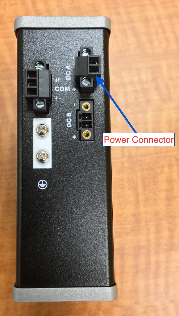
5.![]() Remove the two captive screws that attach the power connector to the switch, and remove the power connector. Remove both connectors if you are connecting to two power sources. See Figure 8.
Remove the two captive screws that attach the power connector to the switch, and remove the power connector. Remove both connectors if you are connecting to two power sources. See Figure 8.
Figure 8 Removing the Power Connectors from the Switch
6.![]() On the power connector, insert the exposed part of the positive wire into the connection labeled “+” and the exposed part of the return wire into the connection labeled “–”. Make sure that you cannot see any wire lead. Only wire with insulation should extend from the connector.
On the power connector, insert the exposed part of the positive wire into the connection labeled “+” and the exposed part of the return wire into the connection labeled “–”. Make sure that you cannot see any wire lead. Only wire with insulation should extend from the connector.
Warning: An exposed wire lead from a DC-input power source can conduct harmful levels of electricity. Be sure that no exposed portion of the DC-input power source wire extends from the connector(s) or terminal block(s). Statement 122
7.![]() Use a ratcheting torque flathead screwdriver to torque the power connector captive screws (above the installed wire leads) to 2in-lb (0.226 Nm).
Use a ratcheting torque flathead screwdriver to torque the power connector captive screws (above the installed wire leads) to 2in-lb (0.226 Nm).
Caution: Do not over-torque the power connector’s captive screws. The torque should not exceed 2in-lb (0.226 Nm).
8.![]() Connect the other end of the positive wire to the positive terminal on the DC power source, and connect the other end of the return wire to the return terminal on the DC power source.
Connect the other end of the positive wire to the positive terminal on the DC power source, and connect the other end of the return wire to the return terminal on the DC power source.
When you are testing the switch, one power connection is sufficient. If you are installing the switch and are using a second power source, repeat Step 4 through Step 8 using the second power connector.
Attaching the Power Connectors to the Switch
To attach the power connectors to the front panel of the switch, follow these steps:
1.![]() Insert one power connector into the DC-A receptacle on the switch front panel, and the other into the DC-B receptacle. See Figure 8.
Insert one power connector into the DC-A receptacle on the switch front panel, and the other into the DC-B receptacle. See Figure 8.
Warning: Installation of the equipment must comply with local and national electrical codes. Statement 1074
2.![]() Use a ratcheting torque flathead screwdriver to tighten the captive screws on the sides of the power connectors to 1.6 in/lbs.
Use a ratcheting torque flathead screwdriver to tighten the captive screws on the sides of the power connectors to 1.6 in/lbs.
Caution: Do not exceed 1.6 In/lbs.
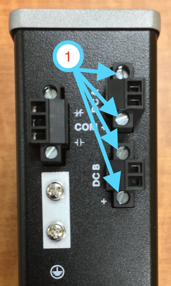
1 |
Captive Screws (Tighten to 1.6 in/lbs) |
When you are testing the switch, one power source is sufficient. If you are installing the switch and are using a second power source, repeat this procedure for the second power connector (DC-B), which installs just below the primary power connector (DC-A).
When you are installing the switch, secure the wires coming from the power connector so that they cannot be disturbed by casual contact. For example, use tie wraps to secure the wires to the rack.
Applying Power to the Power Converter
Move the circuit breaker for the AC outlet or the DC control circuit to the on position.
The LED on the power converter front panel is green when the unit is operating normally. The LED is off when the unit is not powered or is not operating normally. After the power is connected, the switch automatically begins the power-on self- test (POST), a series of tests that verifies that the switch functions properly.
Installing the Switch
This section describes how to install the switch:
■![]() Installing the Switch on a DIN Rail
Installing the Switch on a DIN Rail
■![]() Removing the Switch from a DIN Rail
Removing the Switch from a DIN Rail
Warning: This equipment is supplied as “open type” equipment. It must be mounted within an enclosure that is suitably designed for those specific environmental conditions that will be present and appropriately designed to prevent personal injury resulting from accessibility to live parts. The interior of the enclosure must be accessible only by the use of a tool.
The enclosure must meet IP 54 or NEMA type 4 minimum enclosure rating standards. Statement 1063
Warning: When used in a Class I, Division 2, hazardous location, this equipment must be mounted in a suitable enclosure with proper wiring method, for all power, input and output wiring, that complies with the governing electrical codes and in accordance with the authority having jurisdiction over Class I, Division 2 installations. Statement 1066
Caution: To prevent the switch from overheating, ensure these minimum clearances:
– Top and bottom: 2.0 in. (50.8 mm)
– Exposed side: 1.0 in. (25.4 mm)
– Front: 2.0 in. (50.8 mm)
Installing the Switch on a DIN Rail
The switch ships with a spring-loaded latch on the rear panel for a mounting on a DIN rail.
To attach the switch to a DIN rail, follow these steps:
1.![]() Position the rear panel of the switch directly in front of the DIN rail, making sure that the DIN rail fits in the space between the two hooks near the top of the switch and the spring-loaded latch near the bottom.
Position the rear panel of the switch directly in front of the DIN rail, making sure that the DIN rail fits in the space between the two hooks near the top of the switch and the spring-loaded latch near the bottom.
2.![]() Holding the bottom of the switch away from the DIN rail, place the two hooks on the back of the switch over the top of the DIN rail.
Holding the bottom of the switch away from the DIN rail, place the two hooks on the back of the switch over the top of the DIN rail.
Caution: Do not stack any equipment on the switch.
Figure 9 Switch mounted on DIN Rail
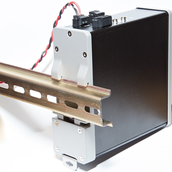
3.![]() Push the switch toward the DIN rail to cause the spring-loaded latch at the bottom rear of the switch to move down, and snap into place.
Push the switch toward the DIN rail to cause the spring-loaded latch at the bottom rear of the switch to move down, and snap into place.
After the switch is mounted on the DIN rail, connect the power and alarm wires, as described in Connecting Alarm Circuits.
Removing the Switch from a DIN Rail
To remove the switch from a DIN rail, follow these steps:
1.![]() Ensure that power is removed from the switch, and disconnect all cables and connectors from the front panel of the switch.
Ensure that power is removed from the switch, and disconnect all cables and connectors from the front panel of the switch.
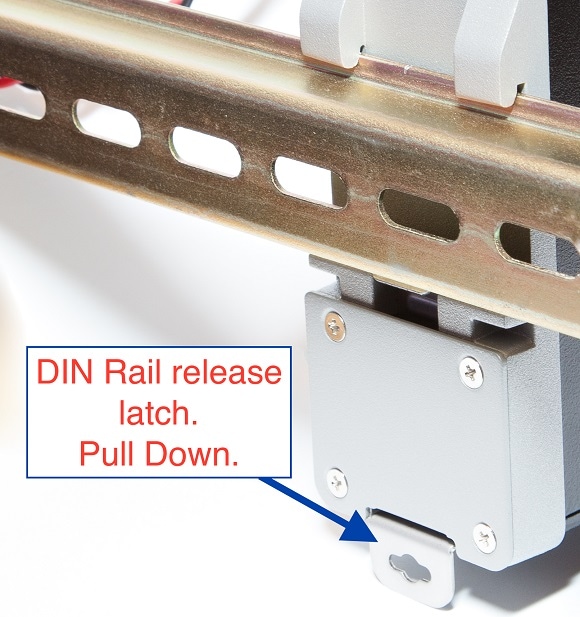
2.![]() Insert a tool such as a flathead screwdriver in the slot at the bottom of the spring-loaded latch and use it to release the latch from the DIN rail. See Figure 10.
Insert a tool such as a flathead screwdriver in the slot at the bottom of the spring-loaded latch and use it to release the latch from the DIN rail. See Figure 10.
3.![]() Pull the bottom of the switch away from the DIN rail, and lift the hooks off the top of the DIN rail. See Figure 10.
Pull the bottom of the switch away from the DIN rail, and lift the hooks off the top of the DIN rail. See Figure 10.
Figure 10 Releasing the Spring-Loaded Latch from the DIN Rail
Connecting Alarm Circuits
After the switch is installed, you are ready to connect the DC power and alarm connections.
■![]() Wiring the Protective Ground and DC Power for Alarm Circuits
Wiring the Protective Ground and DC Power for Alarm Circuits
Wiring the Protective Ground and DC Power for Alarm Circuits
For instructions on grounding the switch and connecting the DC power, see the Grounding the Switch.
Wiring the External Alarms
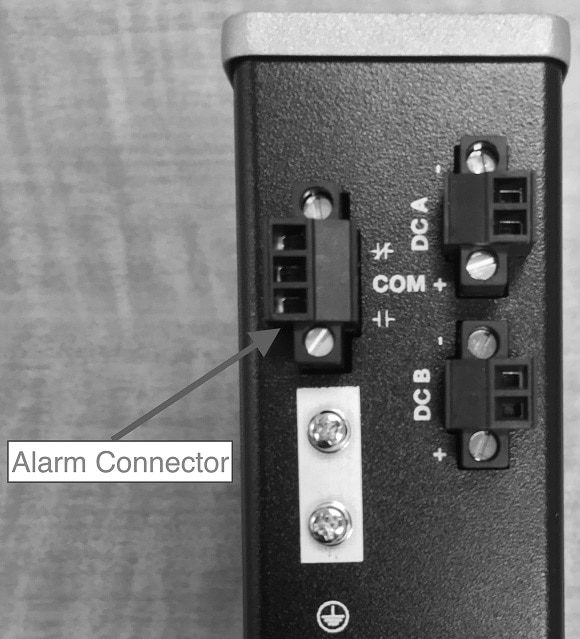
The switch has one alarm output relay circuit for external alarms. The alarm output relay circuit has a normally open and a normally closed contact.
Alarm signals are connected to the switch through the 3-pin alarm connector. The three connections are for the alarm output circuit: a normally open output, a normally closed output, and a common signal. An alarm output and the common wiring connection are required to complete a single alarm output circuit.
The labels for the alarm connector are on the switch panel and are displayed below.
|
|
|
|---|---|
Warning: Explosion Hazard—Do not connect or disconnect wiring while the field-side power is on; an electrical arc can occur. This could cause an explosion in hazardous location installations. Be sure that power is removed or that the area is nonhazardous before proceeding. Statement 1081
Caution: The input voltage source of the alarm output relay circuit must be an isolated source and limited to less than or equal to 24 VDC, 1.0 A or 48 VDC, 0.5 A.
Note: Wire connections to the power and alarm connectors must be UL- and CSA-rated, style 1007 or 1569 twisted-pair copper appliance wiring material (AWM) wire (such as Belden part number 9318).
To wire the switch to an external alarm device, follow these steps:
1.![]() Remove the captive screws that hold the alarm connector on the switch, and remove the connector from the switch chassis. See Figure 11.
Remove the captive screws that hold the alarm connector on the switch, and remove the connector from the switch chassis. See Figure 11.
2.![]() Measure two strands of twisted-pair wire (16-to-18 AWG) long enough to connect to the external alarm device. Choose between setting up an external alarm input or output circuit.
Measure two strands of twisted-pair wire (16-to-18 AWG) long enough to connect to the external alarm device. Choose between setting up an external alarm input or output circuit.
3.![]() Use a wire stripper to remove the casing from both ends of each wire to 0.25 inch (6.3 mm) ± 0.02 inch (0.5 mm). Do not strip more than 0.27 inch (6.8 mm) of insulation from the wires. Stripping more than the recommended amount of wire can leave exposed wire from the alarm connector after installation.
Use a wire stripper to remove the casing from both ends of each wire to 0.25 inch (6.3 mm) ± 0.02 inch (0.5 mm). Do not strip more than 0.27 inch (6.8 mm) of insulation from the wires. Stripping more than the recommended amount of wire can leave exposed wire from the alarm connector after installation.
4.![]() Insert the exposed wires for the external alarm device into the connections based on an alarm input or output circuit setup.
Insert the exposed wires for the external alarm device into the connections based on an alarm input or output circuit setup.
5.![]() Use a ratcheting torque flathead screwdriver to tighten the alarm connector captive screw (above the installed wire leads) to 2 in-lb (0.226 Nm).)
Use a ratcheting torque flathead screwdriver to tighten the alarm connector captive screw (above the installed wire leads) to 2 in-lb (0.226 Nm).)
Caution: Do not over-torque the power and alarm connectors’ captive screws. The torque should not exceed 2 in-lb (0.226 Nm).
6.![]() Repeat Step 2 through Step 5 to insert the input and output wires of one additional external alarm device into the alarm connector.
Repeat Step 2 through Step 5 to insert the input and output wires of one additional external alarm device into the alarm connector.
Attaching the Alarm Connector to the Switch
Warning: Failure to securely tighten the captive screws can result in an electrical arc if the connector is accidentally removed. Statement 397
Warning: When you connect or disconnect the power and/or alarm connector with power applied, an electrical arc can occur. This could cause an explosion in hazardous area installations. Be sure that all power is removed from the switch and any other circuits. Be sure that power cannot be accidentally turned on or verify that the area is nonhazardous before proceeding. Statement 1058
To attach the alarm connector to the front panel of the switch, follow these steps:
1.![]() Insert the alarm connector into the receptacle on the switch top panel.
Insert the alarm connector into the receptacle on the switch top panel.
2.![]() Use a ratcheting torque flathead screwdriver to tighten the captive screws on the sides of the alarm connector to 1.6 in-lbs (0.181 Nm).
Use a ratcheting torque flathead screwdriver to tighten the captive screws on the sides of the alarm connector to 1.6 in-lbs (0.181 Nm).
Connecting Destination Ports
These section provide more information about connecting to the destination ports:
■![]() Installing and Removing SFP Modules
Installing and Removing SFP Modules
Connecting to 10/100 Ports
The switch 10/100 ports automatically configure themselves to operate at the speed of attached devices. If the attached ports do not support autonegotiation, you can explicitly set the speed and duplex parameters. Connecting devices that do not autonegotiate or that have their speed and duplex parameters manually set can reduce performance or result in no linkage.
To maximize performance, choose one of these methods for configuring the Ethernet ports:
■![]() Let the ports autonegotiate both speed and duplex.
Let the ports autonegotiate both speed and duplex.
■![]() Set the port speed and duplex parameters on both ends of the connection.
Set the port speed and duplex parameters on both ends of the connection.
The models that support PoE provide up to eight ports of PoE.
Caution: To prevent electrostatic-discharge (ESD) damage, follow your normal board and component handling procedures.
To connect to 10BASE-T, or 100BASE-T devices, follow these steps:
1.![]() When connecting to workstations, servers, routers, and Cisco IP phones, connect a straight-through cable to an RJ-45 connector on the front panel.
When connecting to workstations, servers, routers, and Cisco IP phones, connect a straight-through cable to an RJ-45 connector on the front panel.
2.![]() Connect the other end of the cable to an RJ-45 connector on the other device. The port LED turns on when both the switch and the connected device have established a link.
Connect the other end of the cable to an RJ-45 connector on the other device. The port LED turns on when both the switch and the connected device have established a link.
The port LED is amber while Spanning Tree Protocol (STP) discovers the topology and searches for loops. This can take up to 30 seconds, and then the port LED turns green. If the port LED does not turn on:
■![]() The device at the other end might not be turned on.
The device at the other end might not be turned on.
■![]() There might be a cable problem or a problem with the adapter installed in the attached device.
There might be a cable problem or a problem with the adapter installed in the attached device.
3.![]() Reconfigure and reboot the connected device if necessary.
Reconfigure and reboot the connected device if necessary.
Installing and Removing SFP Modules
These sections describe how to install and remove SFP modules. SFP modules are inserted into SFP module slots on the front of the switch. These field-replaceable modules provide the uplink optical interfaces, send (TX) and receive (RX).
You can use any combination of rugged SFP modules. Each SFP module must be of the same type as the SFP module on the other end of the cable, and the cable must not exceed the stipulated cable length for reliable communications.
For detailed instructions on installing, removing, and cabling the SFP module, see your SFP module documentation.
Warning: Do not insert and remove SFP modules while power is on; an electrical arc can occur. This could cause an explosion in hazardous location installations. Be sure that power is removed or the area is nonhazardous before proceeding. Statement 1087
Installing SFP Modules into SFP Module Slots
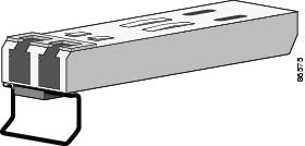
Figure 12 shows an SFP module that has a bale-clasp latch.
Caution: We strongly recommend that you do not install or remove the SFP module with fiber-optic cables attached to it because of the potential damage to the cables, the cable connector, or the optical interfaces in the SFP module. Disconnect all cables before removing or installing an SFP module.
Removing and installing an SFP module can shorten its useful life. Do not remove and insert SFP modules more often than is absolutely necessary.
Figure 12 SFP Module with a Bale-Clasp Latch
To insert an SFP module into the SFP module slot:
1.![]() Attach an ESD-preventive wrist strap to your wrist and to a grounded bare metal surface.
Attach an ESD-preventive wrist strap to your wrist and to a grounded bare metal surface.
2.![]() Find the send (TX) and receive (RX) markings that identify the correct side of the SFP module.
Find the send (TX) and receive (RX) markings that identify the correct side of the SFP module.
On some SFP modules, the send and receive (TX and RX) markings might be replaced by arrows that show the direction of the connection, either send or receive (TX or RX).
3.![]() Align the SFP module sideways in front of the slot opening.
Align the SFP module sideways in front of the slot opening.
4.![]() Insert the SFP module into the slot until you feel the connector on the module snap into place in the rear of the slot.
Insert the SFP module into the slot until you feel the connector on the module snap into place in the rear of the slot.
5.![]() Remove the dust plugs from the SFP module optical ports and store them for later use.
Remove the dust plugs from the SFP module optical ports and store them for later use.
Caution: Do not remove the dust plugs from the SFP module port or the rubber caps from the fiber-optic cable until you are ready to connect the cable. The plugs and caps protect the SFP module ports and cables from contamination and ambient light.
Removing SFP Modules from SFP Module Slots
To remove an SFP module from a module receptacle:
1.![]() Attach an ESD-preventive wrist strap to your wrist and to a grounded bare metal surface.
Attach an ESD-preventive wrist strap to your wrist and to a grounded bare metal surface.
2.![]() Disconnect the LC from the SFP module.
Disconnect the LC from the SFP module.
3.![]() Insert a dust plug into the optical ports of the SFP module to keep the optical interfaces clean.
Insert a dust plug into the optical ports of the SFP module to keep the optical interfaces clean.
4.![]() Unlock and remove the SFP module.
Unlock and remove the SFP module.
If the module has a bale-clasp latch, pull the bale out and down to eject the module. If the bale-clasp latch is obstructed and you cannot use your index finger to open it, use a small, flat-blade screwdriver or other long, narrow instrument to open the bale-clasp latch.
5.![]() Grasp the SFP module between your thumb and index finger, and carefully remove it from the module slot.
Grasp the SFP module between your thumb and index finger, and carefully remove it from the module slot.
6.![]() Place the removed SFP module in an antistatic bag or other protective environment.
Place the removed SFP module in an antistatic bag or other protective environment.
Connecting to SFP Modules
This section describes how to connect to a fiber-optic SFP port. For instructions on how to install or remove an SFP module, see Installing and Removing SFP Modules.
Warning: Class 1 laser product. Statement 1008
Warning: Do not connect or disconnect cables to the ports while power is applied to the switch or any device on the network because an electrical arc can occur. This could cause an explosion in hazardous location installations. Be sure that power is removed from the switch and cannot be accidentally be turned on, or verify that the area is nonhazardous before proceeding. Statement 1070
Caution: Do not remove the rubber plugs from the SFP module port or the rubber caps from the fiber-optic cable until you are ready to connect the cable. The plugs and caps protect the SFP module ports and cables from contamination and ambient light.
Before connecting to the SFP module, be sure that you understand the port and cabling guidelines in the Preparing for Installation.
To connect a fiber-optic cable to an SFP module, follow these steps:
1.![]() Remove the rubber plugs from the module port and fiber-optic cable, and store them for future use.
Remove the rubber plugs from the module port and fiber-optic cable, and store them for future use.
2.![]() Insert one end of the fiber-optic cable into the SFP module port.
Insert one end of the fiber-optic cable into the SFP module port.
3.![]() Insert the other cable end into a fiber-optic receptacle on a target device.
Insert the other cable end into a fiber-optic receptacle on a target device.
4.![]() Observe the port status LED:
Observe the port status LED:
–![]() The LED turns green when the switch and the target device have an established link.
The LED turns green when the switch and the target device have an established link.
–![]() The LED turns amber while the STP discovers the network topology and searches for loops. This process takes about 30 seconds, and then the port LED turns green.
The LED turns amber while the STP discovers the network topology and searches for loops. This process takes about 30 seconds, and then the port LED turns green.
–![]() If the LED is off, the target device might not be turned on, there might be a cable problem, or there might be a problem with the adapter installed in the target device. See Troubleshooting for solutions to cabling problems.
If the LED is off, the target device might not be turned on, there might be a cable problem, or there might be a problem with the adapter installed in the target device. See Troubleshooting for solutions to cabling problems.
5.![]() If necessary, reconfigure and restart the switch or the target device.
If necessary, reconfigure and restart the switch or the target device.
Where to Go Next
If the default configuration is satisfactory, the switch does not need further configuration. You can use any of these management options to change the default configuration:
■![]() Start Device Manager, which is in the switch memory, to manage individual and standalone switches. This is an easy-to-use web interface that offers quick configuration and monitoring. You can access Device Manager from anywhere in your network through a web browser. For more information, see the Express Setup section of the Device Manager online help.
Start Device Manager, which is in the switch memory, to manage individual and standalone switches. This is an easy-to-use web interface that offers quick configuration and monitoring. You can access Device Manager from anywhere in your network through a web browser. For more information, see the Express Setup section of the Device Manager online help.
 Feedback