Running Express Setup
When you first set up the switch, you should use Express Setup to enter the initial IP information. This process enables the switch to connect to local routers and the Internet. You can then access the switch through the IP address for additional configuration.
Required Equipment
You need this equipment to set up the switch:
■![]() Computer with Windows 7/Windows 10/Mac
Computer with Windows 7/Windows 10/Mac
■![]() Web browser (Microsoft Internet Explorer 11, Firefox 46.01 and 47.0, or Microsoft Edge 89.0) with JavaScript enabled. (Disable pop-up blockers and proxy settings and ensure that your browser is using the English EN-US language pack.)
Web browser (Microsoft Internet Explorer 11, Firefox 46.01 and 47.0, or Microsoft Edge 89.0) with JavaScript enabled. (Disable pop-up blockers and proxy settings and ensure that your browser is using the English EN-US language pack.)
Note: Firmware upgrade may fail or will never complete when initiated using a browser language pack other than en-US.
■![]() A straight-through or crossover Category 5 Ethernet cable to connect your computer to the switch port.
A straight-through or crossover Category 5 Ethernet cable to connect your computer to the switch port.
■![]() A small paper clip to reach the express setup button.
A small paper clip to reach the express setup button.
Note: Before running Express Setup, disable any wireless client running on your computer.
Express Setup Procedure
1.![]() Make sure that nothing is connected to the switch.
Make sure that nothing is connected to the switch.
2.![]() Connect power to the switch.
Connect power to the switch.
See the wiring instructions in the “Grounding the Switch” section and the “Wiring the DC Power Source” section on page 19.
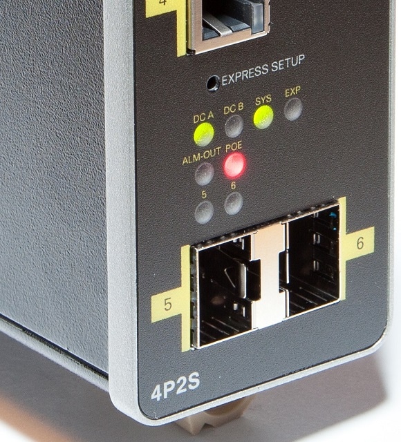
3.![]() Power on or reset the IE 1000:
Power on or reset the IE 1000:
–![]() Use LEDs to monitor boot progress
Use LEDs to monitor boot progress
Sys solid: exit post, initializing
Sys and alarm LEDs green: init done
4.![]() Ensure the IE 1000 is in default factory mode.
Ensure the IE 1000 is in default factory mode.
Skip to next step if freshly out of the box
a.![]() If not freshly out of the package, use a paper clip to reset the switch by depressing the express setup button for 15 - 20 seconds until the EXP LED alternates green - red; then release the paper clip.
If not freshly out of the package, use a paper clip to reset the switch by depressing the express setup button for 15 - 20 seconds until the EXP LED alternates green - red; then release the paper clip.
b.![]() Switch will automatically reboot
Switch will automatically reboot
5.![]() Ensure no data port is connected to the switch.
Ensure no data port is connected to the switch.
Note : During Express Setup, the switch acts as a DHCP server.
–![]() Ensure the computer connected to switch is configured to receive an IP address from the DHCP server.
Ensure the computer connected to switch is configured to receive an IP address from the DHCP server.
6.![]() Insert paper clip into express setup button for 1-2 seconds
Insert paper clip into express setup button for 1-2 seconds
–![]() When released, EXP LED starts flashing green.
When released, EXP LED starts flashing green.
7.![]() Connect computer to port Fa 1/1, LED continues to blink
Connect computer to port Fa 1/1, LED continues to blink
8.![]() Ensure the computer has received the IP Address 192.168.1.1,
Ensure the computer has received the IP Address 192.168.1.1,
9.![]() Point browser to http://192.168.1.254
Point browser to http://192.168.1.254
10.![]() Leave the username blank and enter the default password, cisco.
Leave the username blank and enter the default password, cisco.
Note The Express Setup window appears.
a.![]() Troubleshooting: If the Express Setup window does not appear, make sure that any pop-up blockers or proxy settings on your browser are disabled and that any wireless client is disabled on your computer.
Troubleshooting: If the Express Setup window does not appear, make sure that any pop-up blockers or proxy settings on your browser are disabled and that any wireless client is disabled on your computer.
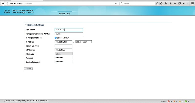
11.![]() Enter all entries in English letters and Arabic numbers.
Enter all entries in English letters and Arabic numbers.
In the Network Settings (Required for Static IP):
–![]() New Admin User: Password must be from 8-31 characters long, contain upper and lower case characters, a number and a symbol (!@#$%^).
New Admin User: Password must be from 8-31 characters long, contain upper and lower case characters, a number and a symbol (!@#$%^).
–![]() IP Address : Enter a valid IP address for the switch.
IP Address : Enter a valid IP address for the switch.
You can later use the IP address to access the switch through Device Manager.
–![]() (Optional) Default Gateway: Enter the IP address of the router.
(Optional) Default Gateway: Enter the IP address of the router.
Note: The Device manager will not allow you to exit the express setup page if the static IP address of the IE 1000 and the Default Gateway are not in the same subnet.
You can enter the optional information now, or enter it later by using Device Manager. For more information about the Express Setup fields, see the on-line help for the Express Setup window.
Click Submit to save your changes and to complete the initial setup.
For more information about the optional settings, click Help on the tool-bar.
13.![]() After you click Submit, these events occur:
After you click Submit, these events occur:
a.![]() The switch is configured and exits Express Setup mode.
The switch is configured and exits Express Setup mode.
b.![]() The browser displays a warning message, instructing the user to clear browser cookies.
The browser displays a warning message, instructing the user to clear browser cookies.
c.![]() Typically, connectivity between the computer and the switch is lost because the configured switch IP address is in a different subnet from the IP address on the computer.
Typically, connectivity between the computer and the switch is lost because the configured switch IP address is in a different subnet from the IP address on the computer.
d.![]() If you changed the Management Interface Vlan ID, then after pressing submit, all Ethernet interfaces on the IE 1000 are now members of this new vlan. This is to enable the connection to the network.
If you changed the Management Interface Vlan ID, then after pressing submit, all Ethernet interfaces on the IE 1000 are now members of this new vlan. This is to enable the connection to the network.
14.![]() Remove the PC and connect the switch to the network as configured in step 12.
Remove the PC and connect the switch to the network as configured in step 12.
Note: After power cycling, the IE 1000 will not act as DHCP server. DHCP Server behavior is special to Express Setup. to reconnect to the IE 1000 after the power cycle you will need to A) configure a static IP Address on your PC that is in the same subnet as the IP Address you just assigned, or B) connect to the new IP Address of the IE 1000 from the network.
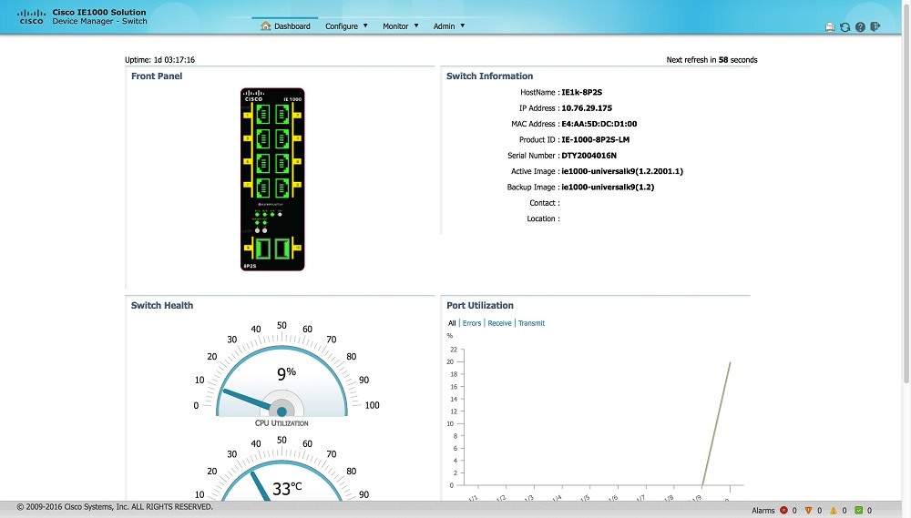
15.![]() You can now manage the switch by using the Device Manager. See the “Managing the Switch” section on page 9 for information about configuring and managing the switch.
You can now manage the switch by using the Device Manager. See the “Managing the Switch” section on page 9 for information about configuring and managing the switch.
You can display Device Manager by following these steps:
a.![]() Start a web browser on your computer.
Start a web browser on your computer.
b.![]() Enter the switch IP address, username, and password in the web browser, and press Enter. The Device Manager page appears.
Enter the switch IP address, username, and password in the web browser, and press Enter. The Device Manager page appears.
If the Device Manager page does not appear:
–![]() Ping the IP address of device from PC where browser is getting launched. If not check Computer's network connectivity.
Ping the IP address of device from PC where browser is getting launched. If not check Computer's network connectivity.
–![]() Confirm that the port LED for the switch port connected to your network is green.
Confirm that the port LED for the switch port connected to your network is green.
–![]() Confirm that the computer that you are using to access the switch has network connectivity by connecting it to a well known web server in your network. If there is no network connection, troubleshoot the network settings on the computer.
Confirm that the computer that you are using to access the switch has network connectivity by connecting it to a well known web server in your network. If there is no network connection, troubleshoot the network settings on the computer.
–![]() Make sure that the switch IP address in the browser is correct.
Make sure that the switch IP address in the browser is correct.
–![]() If the switch IP address in the browser is correct, the switch port LED is green, and the computer has network connectivity, continue troubleshooting by reconnecting the computer to the switch. Configure a static IP address on the computer that is in the same subnet as the switch IP address.
If the switch IP address in the browser is correct, the switch port LED is green, and the computer has network connectivity, continue troubleshooting by reconnecting the computer to the switch. Configure a static IP address on the computer that is in the same subnet as the switch IP address.
–![]() When the LED on the switch port connected to the computer is green, reenter the switch IP address in a web browser to display the Device Manager. When Device Manager appears, you can continue with the switch configuration.
When the LED on the switch port connected to the computer is green, reenter the switch IP address in a web browser to display the Device Manager. When Device Manager appears, you can continue with the switch configuration.
 Feedback