Product Overview
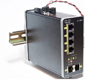
The Cisco® Industrial Ethernet (IE) 1000 Series Switches are compact rugged switches aimed to operational technology (OT) users with limited IT network knowledge. The IE 1000 Series Switches provide an easy transformation from the legacy factory to digital solution. For machine builders and machine-to-machine (M2M) solutions is an attractive entry level product as a GUI-based, lightly-managed switch. The 1000 is a good fit for locations with harsh temperatures and small spaces, and is Power over Ethernet (PoE) capable with and zero IT management.
The 1000 is ideal for industrial Ethernet applications where small and easy-to-be-managed hardened products are required, including factory automation, intelligent transportation systems, city-surveillance programs, building automations etc.
The Cisco IE 1000 Series Switches complement the current industrial Ethernet portfolio of related Cisco industrial switches, such as the Cisco IE 2000, IE 3000, IE 4000 and IE 5000 Series Switches.
The 1000 can be easily installed on your network. Through a user-friendly web device manager, the 1000 provides easy out-of-the-box configuration and simplified operational manageability to deliver advanced and secure multiservices over industrial networks.
Front Panel Overview
The illustrations in this section provide an overview of the variety of components available on the various switch models in this product family. Not all models are illustrated.
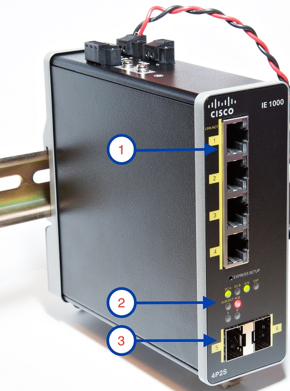
Figure 1 Cisco IE-1000-4P2S-LM front panel shown
|
|
|
|
|
|
|
|
|
|
Ports and Slots
Note: Different configurations are available. Not all ports or slots are present in all configurations.
10/100 BASE-T Downlink Ports
You can set the 10/100BASE-T downlink ports to operate at 10 or 100 Mb/s in full-duplex or half-duplex mode. You can also set these ports for speed and duplex autonegotiation in compliance with IEEE 802.3AB. (The default setting is autonegotiate.) When set for autonegotiation, the port senses the speed and duplex settings of the attached device and advertises its own capabilities. If the connected device also supports autonegotiation, the switch port negotiates the best connection (that is, the fastest line speed that both devices support, and full-duplex transmission if the attached device supports it) and configures itself accordingly. In all cases, the attached device must be within 328 feet (100 meters). 100BASE-TX traffic requires Category 5 cable. 10BASE-T traffic can use Category 3 or Category 4 cables.
When connecting the switch to workstations, servers, routers, and Cisco IP phones, make sure that the cable is a straight-through cable.
100/1000 Mb/s SFP Module Uplink Slots
The IEEE 802.3u 100 Mb/s SFP module uplink slots provide full-duplex 100 or 1000 Mb/s connectivity over multi-mode (MM) fiber cables or single-mode (SM) fiber cables. These ports use a SFP fiber-optic transceiver module that accepts a dual LC connector. Check the SFP specifications for the cable type and length.
SFP Modules Supported
The SFP modules are switch Ethernet SFP modules that provide connections to other devices. Depending on the switch model, these field-replaceable transceiver modules provide uplink or downlink interfaces. The modules have LC connectors for fiber-optic connections. For a complete list of supported SFP modules refer to the Data Sheet.
Connectors
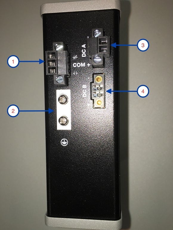
Figure 2 Cisco IE-1000-4P2S-LM top panel shown
|
|
|
|
|
|
|
|
|
|
DC Power Connector
You connect the DC power to the switch through the top panel connectors. The switch has a dual-feed DC power supply; two connectors provide primary and secondary DC power (DC-A and DC-B). See Figure 1. Each power connector has an LED status indicator.
The switch power connectors are attached to the switch chassis. Each power connector has screw terminals for terminating the DC power. All connectors are attached to the switch top panel with the provided captive screws.
The power connector labeling is on the panel. The positive DC power connection is labeled “ +”, and the return connection is labeled “ –”.
The switch can operate with a single power source or with dual power sources. When both power sources are operational, the switch draws power from the DC source with the higher voltage. If one of the two power sources fail, the other continues to power the switch.
Alarm Connector (PoE Models Only)
You connect the alarm signals to the switch through the alarm connector. The switch supports one alarm output relay. The alarm connector is on the top panel.
The alarm connector provides three alarm wire connections. The connector is attached to the switch top panel with the provided captive screws.
The alarm output circuit is a relay with a normally open and a normally closed contact. The switch is configured to detect faults that are used to energize the relay coil and change the state on both of the relay contacts: normally open contacts close, and normally closed contacts open. The alarm output relay can be used to control an external alarm device, such as a bell or a light.
For more information about the alarm connector, see Cable and Connectors
LEDs
You can use the LEDs to monitor the switch status, activity, and performance. Figure 3 and show the front panel LEDs.
Figure 3 LEDs on the Cisco IE 1000 Switch (PoE Models Only)
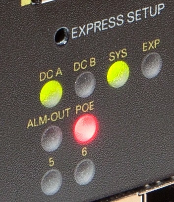
Express Setup LED
The Express Setup LED displays the express setup mode for the initial configuration.
System LED
The System LED shows whether the system is receiving power and is functioning properly.
Alarm OUT (PoE Models Only)
Power Status LEDs
The switch can operate with one or two DC power sources. Each DC input has an associated LED that shows the status of the corresponding DC input. If power is present on the circuit, the LED is green. If power is not present, the LED color depends on the alarm configuration. If alarms are configured, the LED is red when power is not present; otherwise, the LED is off.
If the switch has dual power sources, the switch draws power from the power source with the higher voltage. If one of the DC sources fails, the alternate DC source powers the switch, and the corresponding power status LED is green.
The Power A and Power B LEDs show that power is not present on the switch if the power input drops below the low valid level. The power status LEDs only show that power is present if the voltage at the switch input exceeds the valid level.
Port Status LEDs
Each port and SFP uplink slot has a status LED, as shown in Figure 3 and described below.
PoE Status LED
The PoE STATUS LEDs are located on the front panel of POE capable models. The LEDs display the functionality and status of the adjacent PoE ports.
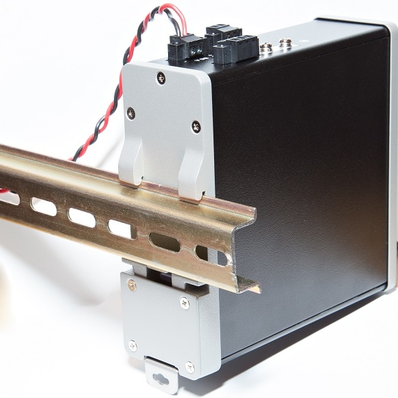
Rear Panel
The rear panel of the switch has a latch for installation on a DIN rail. See Figure 4. The latch is spring-loaded to move down to position the switch over a DIN rail and return to the original position to secure the switch to a DIN rail.
Figure 4 Cisco IE 1000 Switch Rear Panel
Management Options
The switch supports these management options:
You can use Device Manager, which is in the switch memory, to manage individual and standalone switches. This web interface offers quick configuration and monitoring. You can access Device Manager from anywhere in your network through a web browser.
Network Configurations
See the switch software configuration guide on Cisco.com for network configuration concepts and examples of using the switch to create dedicated network segments and interconnecting the segments through Gigabit Ethernet connections.
 Feedback