
Cisco C9610 Series Smart Switches - Install the Switch
Install the chassis
This section describes the different methods to install the Cisco C9610 series smart switches.
- Install the switch on 19-inch shelf brackets.
- Install the switch on 23-inch shelf brackets.
- Install the switch in Network Equipment-Building System (NEBS)-compliant mode.
Install the switch on 19-inch shelf brackets
To install the switch on 19-inch shelf brackets
- If required, attach the cable guides on the chassis with the preinstalled L-brackets, then
- rack-mount the chassis.
Attach cable guides on the chassis with preinstalled L-brackets
You can also install the chassis on 19-inch shelf brackets, without attaching the cable guides.
The 19-inch shelf brackets are part of the standard accessory kit, C9610-19-KIT-4 that is shipped with the switch. The cable guides or cable management brackets are optional accessories.
Before you begin
Open the accessory kit and ensure that you have received all items.
Two sets of backplates are part of the 53-102061-01 kit. The backplates are not used for 19-inch rack mounting, but for 23-inch rack mounting.
Step 1 | Remove and discard the two L-brackets and the 20 mounting screws that the chassis is shipped with. Do not re-use them during any part of the installation process. |
Step 2 | Position the cable guides to align with the L-brackets preinstalled on the chassis. |
Step 3 | Secure the cable guides to the L-brackets using a screw on each side. Use the M3 pan head screw from the 53-102061-01 kit. |
Step 4 | Position the preinstalled L-brackets on the chassis to align with the rack rails. |
Step 5 | Secure the L-brackets and cable guides to the rack rails by using 13 screws on each side. Use either 10-32, 12-24, or M6 pan head screws from the C9610-19-KIT-4 kit. 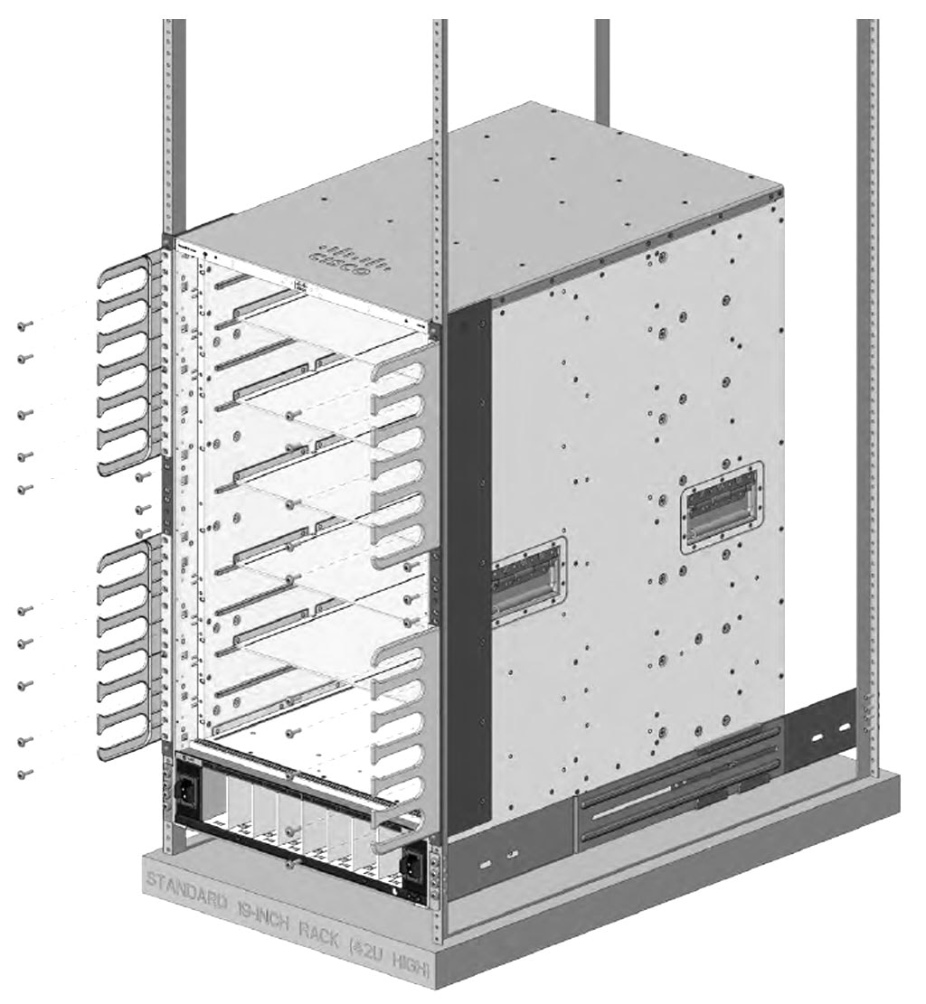
|
Attaching cable guides on 19-inch shelf brackets is complete.
Rack-mounting the chassis on 19-inch brackets
Install the shelf brackets before you install the chassis in the rack to help support the weight of the chassis while you secure the L-brackets to the rack enclosure. You have to mount the shelf brackets from the front and rear.
Determine the clearance between the insides of the left and right rails of your rack system and install the shelf brackets accordingly.
Ensure that you have the required tools and accessories.
- Number 1 and number 2 Phillips screwdrivers
- 3/16-inch flat-blade screwdriver
- Tape measure and level
Before you begin
 Warning
Statement 1006—Chassis Warning for Rack-Mounting and Servicing
To prevent bodily injury when mounting or servicing this unit in a rack, you must take special precautions to ensure that the system remains stable. The following guidelines are provided to ensure your safety:
- This unit should be mounted at the bottom of the rack if it is the only unit in the rack.
- When mounting this unit in a partially filled rack, load the rack from the bottom to the top with the heaviest component at the bottom of the rack.
- If the rack is provided with stabilizing devices, install the stabilizers before mounting or servicing the unit in the rack.
WarningStatement 1032—Lifting the Chassis
To prevent personal injury or damage to the chassis, never attempt to lift or tilt the chassis using the handles on modules, such as power supplies, fans, or cards. These types of handles are not designed to support the weight of the unit.
WarningStatement 1098— Lifting Requirement
Two or more people are required to lift the heavy parts of the product. To prevent injury, keep your back straight and lift with your legs, not your back.
Step 1 | Remove and discard the two L-brackets and the 20 mounting screws that the chassis is shipped with. Do not re-use them during any part of the installation process. | ||||
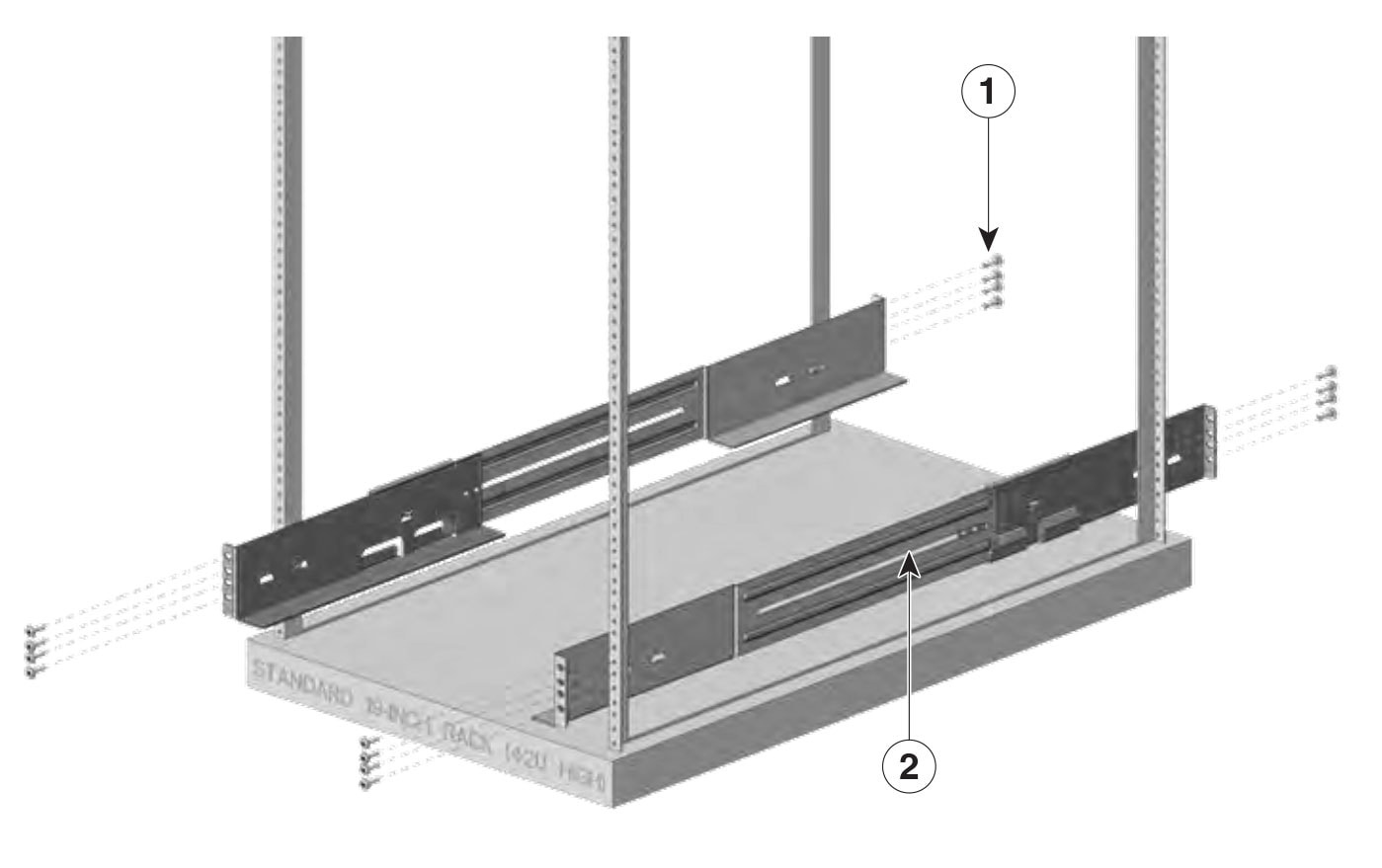
Step 2 | Assemble the left and right shelf brackets on to the rack.
| ||||
Step 3 | Insert the chassis between the shelf brackets and slide it in. 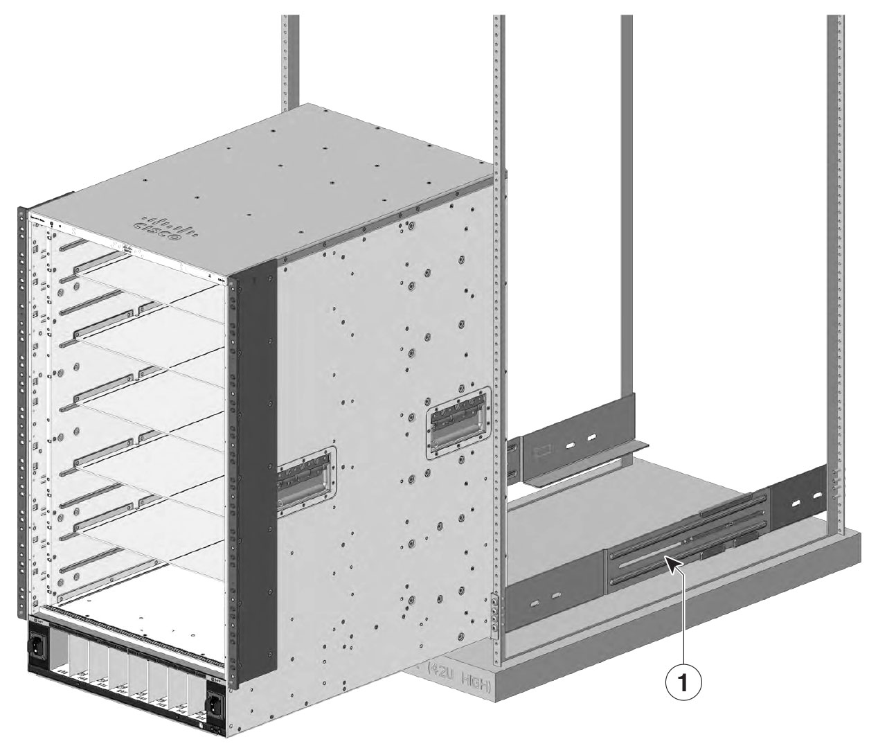
| ||||
Step 4 | Align the mounting holes in the L-brackets with the rack rails or on the cable mount (if installed) with the mounting holes in the equipment rack. Use 13 screws on each side to mount the brackets. | ||||
Step 5 | Assemble and mount both the chassis rear-mounting brackets on to the chassis from rear. Mount the brackets using three screws on each side. | ||||
Step 6 | Assemble and mount both the rear rack-mounting brackets on to the rack. Mount the brackets using four screws on each side. 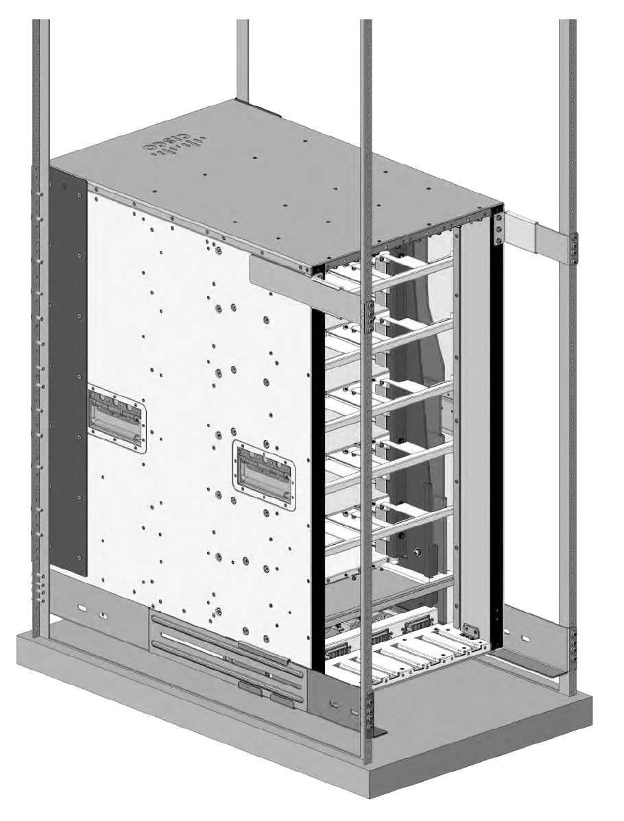
| ||||
Step 7 | Use a tape measure and level to ensure that the chassis is installed straight and level. |
What to do next
After installing the chassis in its location, complete the installation process by
- connecting the chassis to system ground,
- installing and connecting the power supplies to the power source,
- connecting the network interface cables to the supervisor module and line card modules. This may involve installing transceivers before you attach the network interface cables, and
- powering up the chassis and verifying the installation.
Install the switch in NEBS-compliant mode
This section describes
- The NEBS-compliant air filter.
- How to install the NEBS-compliant cable guides.
- How to rack mount the Cisco C9610 series smart switches in NEBS-compliant mode.
NEBS-compliant air filter
An NEBS-compliant installation allows filtered, front-to-rear airflow. To mount the chassis in NEBS-compliant mode with the air filter, use a 19-inch rack mount. Filter brackets that are mounted on the side of the chassis to hold the air filter.
A 19-inch rack mount is used for mounting the switch in a standard 19 inches (48.26 cms) equipment rack with two unobstructed outer posts. This kit is not suitable for racks with obstructions (such as a power strip) that could impair access to the field-replaceable units (FRUs) of the switch.
Rack mount the chassis in NEBS-compliant mode
Before you begin
- Read the safety warnings carefully before starting any installation procedure to make sure you understand the hazards and precautions.
- Place the chassis on the floor or on a sturdy table as close as possible to the rack. Leave enough clearance to allow you to move around the chassis.
- Open the NEBS rack-mount kit (C9610-NEBS-KIT=) and verify that all parts are included.
-
Make sure that you have the required tools and accessories.
- Phillips screwdriver with a torque capability
- Cable management brackets
 Note
NoteSome equipment racks provide a power strip along the length of one of the rear posts. If your rack has this feature, consider the position of the strip when planning fastener points. Before installing the brackets on the chassis, determine whether to install the chassis from the front or the rear of the rack.
Perform this task to rack mounting the switch in NEBS-compliant mode.
Step 1 | Attach the cable guides on the chassis. For more information, see Attach cable guides on the chassis with preinstalled L-brackets task. |
Step 2 | Position the cable guides to align with the vertical mounting brackets preinstalled on the chassis and secure the cable guides to the vertical mounting brackets. Use the M3 pan head screws from the C9610-NEBS-KIT to secure the cable guides to the vertical mounting brackets. |
Step 3 | Secure the left and right cable guides to the chassis. Use the pan head screws provided in the standard accessory kit, C9610-19-KIT-4. |
Step 4 | Install the top and bottom hood covers. Position the top and bottom hood assembly in between the left and right cable guides, and secure the hoods. Use flat head M3 screws from the C9610-NEBS-KIT to secure the top and bottom hood assembly. |
Step 5 | Install the right and the left doors.
Ensure the spring pins are properly inserted into the holes so that the doors can freely swing open on the spring pins. |
Step 6 | Install the shoulder screws at the top and bottom of both the door frames to secure the door. Use the number 4 Allen tool to fix the four screws. |
Step 7 | Attach the grounding cable on the left and right to the cable guides. Use M3 pan head screws from C9610-NEBS-KIT. |
Step 8 | To replace the NEBS air filter, open either the right or left door assembly, and remove the air filter.
|
Step 9 | Install the new air filter from C9610-NEBSFILTER kit, and then install the removed door assembly
|
Establish system ground
Perform these steps to attach the grounding lug and cable to the grounding pad.
Grounding lug can be installed on the front and rear of the chassis.
Before you begin
WarningStatement 1046—Installing or Replacing the Unit
To reduce risk of electric shock, when installing or replacing the unit, the ground connection must always be made first and disconnected last.
If your unit has modules, secure them with the provided screws.
To connect the system ground, you require these tools and materials:
- Grounding lug: a two-hole grounding lug, which supports up to 6 American Wire Gauge (AWG) size. Supplied as part of the standard accessory kit.
- Grounding screws: two M4 x 8 mm (metric) pan-head screws. Supplied as part of the standard accessory kit.
- Grounding wire: the grounding wire should be sized according to local and national installation requirements. Depending on the power supply and system, a 12 to 6 AWG copper conductor is required for U.S. installations. Commercially available 6-AWG wire is recommended. The length of the grounding wire depends on the proximity of the switch to proper grounding facilities.
- No. 1 Phillips screwdriver.
- Crimping tool to crimp the grounding wire to the grounding lug.
- Wire-stripping tool to remove the insulation from the grounding wire.
Step 1 | Use a wire-stripping tool to remove approximately 0.75 inches (19 mm) of the covering from the end of the grounding wire. |
Step 2 | Insert the stripped end of the grounding wire into the open end of the grounding lug. |
Step 3 | Crimp the grounding wire in the barrel of the grounding lug. Verify that the ground wire is securely attached to the ground lug. |
Step 4 | Secure the grounding lug to the system ground connector with two M4 screws. Ensure that the grounding lug and the grounding wire do not interfere with other switch hardware or rack equipment. |
Step 5 | Prepare the other end of the grounding wire, and connect it to an appropriate grounding point in your site to ensure adequate earth ground for the switch. 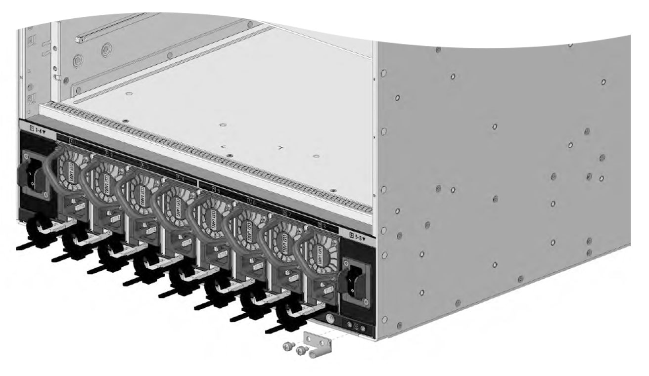
|
Attach an ESD strap
After you install the system ground lug, follow these steps to correctly attach the electrostatic discharge (ESD) wrist strap.
Step 1 | Attach the ESD wrist strap to bare skin.
|
Step 2 | Grasp the spring or alligator clip on the ESD wrist strap and momentarily touch the clip to a bare metal spot (unpainted surface) on the rack. We recommend that you touch the clip to an unpainted rack rail so that any built-up static charge is then safely dissipated to the entire rack. |
Step 3 | Attach either the spring clip or the alligator clip to the ground lug screw as follows:
Follow these guidelines, when handling modules.
|
Install a fan tray
The Cisco C9610 series smart switches ship with preinstalled fan trays. Before removing or installing a fan tray ensure that you follow the guidelines and safety warnings.
 Caution
Online insertion and removal
While the fan tray is designed to be removed and installed while the system is operational (powered on) without presenting an electrical hazard or damage to the system, there is a time constraint when you remove and replace the fan tray in a system that is powered on.
CautionThe system can safely run without a fan tray only for a few minutes, until the critical temperature threshold is exceeded. Watch for any alarms triggered in the software. After the critical temperature threshold exceeds without sufficient cooling, the system shuts down if the alarm is not cleared.
You can remove and replace the fan tray only from the rear of the chassis.
When you remove and replace a fan tray in a non-operating system, there is no time constraint.
When you order a spare, a fan tray that contains six fans and a connector are shipped. Even if one of the fans is not functioning and you need to replace the fan, you must order a fan tray; individual fans cannot be ordered.
Remove a fan tray
Fan trays are hot-swappable. You do not need to power down the system to remove fan trays.
Before you begin
- Read the safety instructions in the Install a fan tray section.
-
Ensure that you have these tools and accessories available
- Phillips-head screwdriver, and an
- anti-static mat.
Step 1 | Keep the replacement fan tray ready by removing it from the shipping packaging. Place it on an anti-static mat and within arm's reach. Do not detach the connector module. NoteWhen you remove and replace the fan tray in a system that is powered on, there is a time constraint. The system can safely run without a fan tray only for 2 minutes. So it is important to complete this first step before you remove the fan tray from the rear of the chassis. |
Step 2 | Proceed with removing the fan tray from the chassis. Loosen the four captive installation screws on the fan tray until the screws are free of the chassis. 
In PDF, to view the animation, click this link. |
Step 3 | Hold both the handles of the fan tray and remove the fan tray assembly completely out of the bay. 
In PDF, to view the animation, click this link. |
What to do next
Set the removed fan tray on an anti-static mat and proceed with installing the replacement or spare fan tray.
Install a fan tray
When inserting the fan tray, make sure that the Cisco logo on the fan tray must be on the top.
Before you begin
- Read the safety warnings.
-
Ensure that you have the following tools and accessories available:
- Phillips-head screwdriver
- Anti-static mat
Step 1 | On the replacement fan tray assembly, ensure that the four screws securing the fan tray to the connector are tight. Be careful not to overtighten the screws. |
Step 2 | Hold both the fan tray assembly handles. |
Step 3 | Position the fan tray with its rear (the side with the electrical connectors) at the opening of the fan tray slot in the chassis. |
Step 4 | Align the two tracks on the top of the fan tray with the two sets of rails at the top of the fan tray slot in the chassis. NoteIf you try to insert the fan tray in inverse, you will not be able to insert it into the bay. Ensure that the top and bottom of the fan tray is aligned to the top and bottom of the bay. 
In PDF, to view the animation, click this link. |
Step 5 | Slide the fan tray slowly into the chassis with both your hands, until the four captive installation screws make contact with the chassis. Do not slam in the fan tray into the slot. Plug in the fan tray slowly |
Step 6 | Tighten the four (two at the top and two at the bottom of the fan tray) captive installation screws and secure the fan tray assembly in the chassis. 
In PDF, to view the animation, click this link. |
What to do next
Verify that the fan tray status LED turns green within 20 seconds after the installation.
Verify the fan tray installation
Follow these steps to verify that the new fan tray is installed correctly and is operating properly.
Before you begin
To check the operation of the fans, you have to power up the chassis.
Step 1 | Listen to the sound of the fans; you should immediately hear them operating. If you do not hear the sound, ensure that the
ImportantIf the fan tray is not installed correctly, the fans may not run at all, or they may run at full speed. When the fan tray operates at full speed, increased noise levels may be expected. |
Step 2 | Check if the fan tray LED is lit and is green. |
Step 3 | Even after several attempts if the fans do not operate, or if you experience trouble with the installation (for instance, if the captive installation screws do not align with the chassis holes), contact the Cisco TAC for assistance. |
Install a power supply module
Cisco C9610 series smart switches ship with preinstalled power supply modules. This section describes how to remove and install the power supply modules.
Required tools and equipments
To install a power supply unit on a Cisco C9610 switch, you need
- Phillips-head screwdriver
- 10-mm torque driver (with a 3-inch shaft, at a minimum)
- Wire-stripping tool
- Wire-crimping tool
Remove and reinstall power supply modules
The chassis supports field-replaceable and hot-swappable AC-input and DC-input power supply modules. You can install a mix of AC-input and DC-input modules in the chassis. This section describes how to remove and install both kinds of modules and safety warnings to adhere to.
- In redundant mode, you do not have to power down the switch to replace or upgrade the power supplies.
- In combined mode, the module is still hot-swappable as long as the difference between total output power and the total used power is greater than the capacity of the module being removed. Total output power: Total used > Capacity of power supply module being removed.
WarningStatement 1003—DC Power Disconnection
To reduce risk of electric shock or personal injury, disconnect DC power before removing or replacing components or performing upgrades.
WarningStatement 1005— Circuit Breaker
This product relies on the building’s installation for short-circuit (overcurrent) protection. To reduce risk of electric shock or fire, ensure that the protective device is rated not greater than: 20A for AC and 60A for DC.
WarningStatement 1017—Restricted Area
This unit is intended for installation in restricted access areas. Only skilled, instructed, or qualified personnel can access a restricted access area.
WarningStatement 1022—Disconnect Device
To reduce the risk of electric shock and fire, a readily accessible disconnect device must be incorporated in the fixed wiring.
WarningStatement 1073—No User-Serviceable Parts
There are no serviceable parts inside. To avoid risk of electric shock, do not open.
Remove a power supply module
Before you begin
WarningStatement 1073—No User-Serviceable Parts
There are no serviceable parts inside. To avoid risk of electric shock, do not open.
Step 1 | Turn the power switch of the designated power supply module to OFF (0) position. |
Step 2 | Loosen and remove the retainer strip that is around the power cord. |
Step 3 | Remove the power cord from the power receptacle on the power supply. |
Step 4 | Press the release latch at the bottom of the power supply module upwards. 
In PDF, to view the animation, click this link. |
Step 5 | Grasp the power supply module handle with one hand, and slide the power supply module out fully. 
In PDF, to view the animation, click this link. CautionDo not leave any power supply slot open for any amount of time while the system is powered up. Before inserting a new power supply unit, for instance, when replacing the unit, ensure that there are no foreign, conductive or other objects, or debris in the slot. WarningStatement 1028—More Than One Power Supply This unit might have more than one power supply connection. To reduce risk of electric shock, remove all connections to de-energize the unit.  |
What to do next
Set the power supply aside and proceed with installing the new or replacement power supply module. Install blank covers in all power supply bays that are to remain empty (C9600-PWR-BLANK). For information about installing blank covers, see Remove and reinstall power supply blanks.
Install a power supply module
Before you begin
WarningStatement 1073—No User-Serviceable Parts
There are no serviceable parts inside. To avoid risk of electric shock, do not open.
Ensure that you have installed the cable guide before you begin this procedure. This is to properly guide and arrange the power cords that you will attach as part of the installation.
Step 1 | Remove the replacement power supply from its shipping packaging. |
Step 2 | Verify that the power switch of the replacement power supply is in the OFF (0) position. |
Step 3 | If installed, remove the blank power supply cover from the empty power supply bay. For information about removing blank covers, see Remove and reinstall power supply blanks. Save the blank cover for future use. |
Step 4 | Grasp the power supply handle with one hand and slide the power supply all the way into the power supply bay. Make sure that the power supply is fully seated in the bay. 
In PDF, to view the animation, click this link.
|
Step 5 | Verify that all site power and grounding requirements have been met. |
Step 6 | Verify that you have the correct power cord for your location and power supply rating and only then plug the power cord connector into the power supply receptacle. |
Step 7 | Follow the steps to install the power cord retainer, to hold it in place and avoid accidental removal.
|
Step 8 | Set the power switch to the ON (|) position |
What to do next
Connect the power supply to the power source.
Connect to an AC power source
Step 1 | Prior to connecting the power supply to a power source, ensure that the chassis is properly grounded. |
Step 2 | Plug the power cable into the AC power receptacle on the power supply module. |
Step 3 | Plug the other end of the power cable into a power source supplied by the data center. NoteWhen using redundant mode, connect each power supply to a separate power source. |
Step 4 | Verify that the power supply is receiving power by checking that the LED is on and is green. For more information about the power supply LEDs and the conditions that they indicate, see Power supply module LEDs. When you first activate the power supply, you can verify the functionality of the LED by checking that LED turns on for a couple of seconds. If the LED is flashing amber or green, check the power connections on the power supply and the power source. |
Connect to a DC power source
To connect the DC power supply directly to one or two DC power sources, follow these steps.
Before you begin
WarningStatement 1022—Disconnect Device
To reduce the risk of electric shock and fire, a readily accessible disconnect device must be incorporated in the fixed wiring.
WarningStatement 1033—Safety Extra-Low Voltage (SELV)—IEC 60950/ES1–IEC 62368 DC Power Supply
To reduce the risk of electric shock, connect the unit only to a DC power source that complies with the SELV requirements in the IEC 60950-based safety standards or the ES1 requirements in the IEC 62368-based safety standards.
Step 1 | Prior to connecting the power supply to a power source, ensure that the chassis is properly grounded. | ||||
Step 2 | Plug the DC power cable into the DC power receptacle on the power supply module. 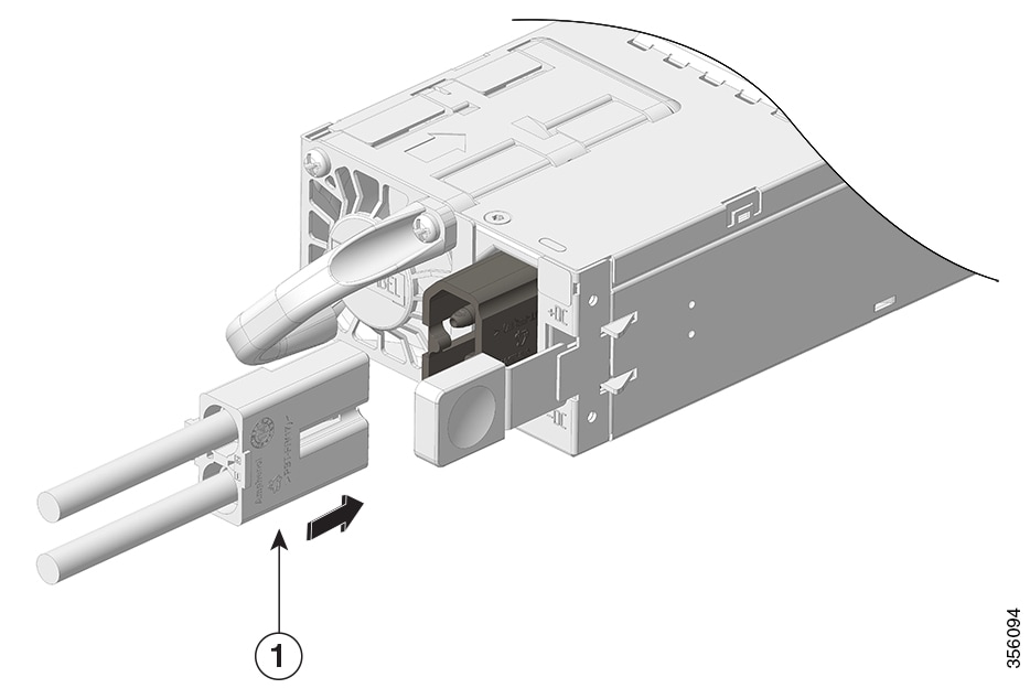
| ||||
Step 3 | Turn off the power at the circuit breakers for the portions of the DC grid power that you are connecting to and verify that all of the LEDs on the DC grid power supplies are off. | ||||
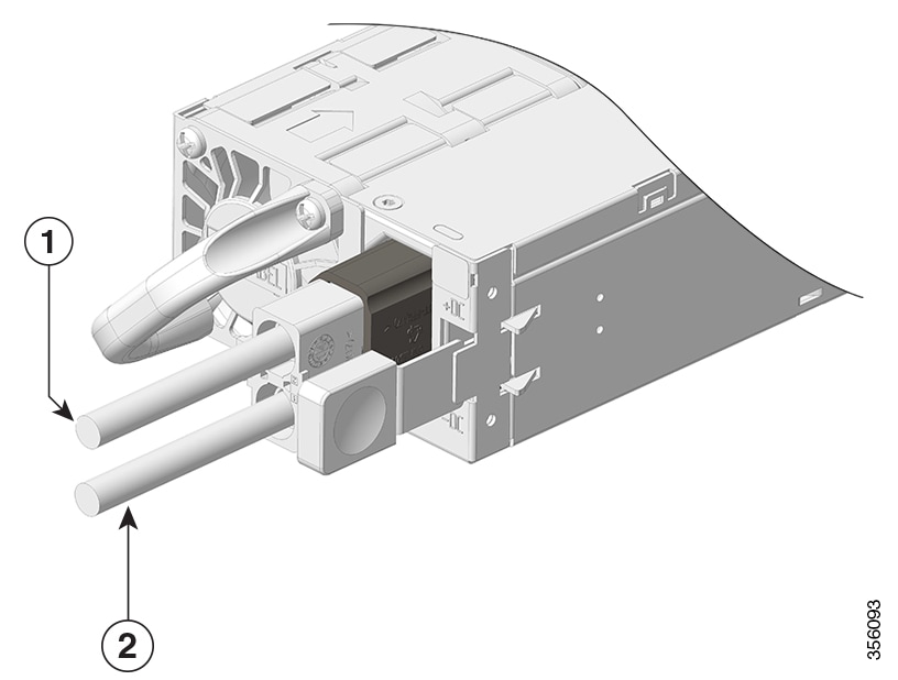
Step 4 | Install the two cables from the DC power cable to a DC power source as follows:
NoteIf you are using combined power mode or power supply redundancy mode, connect all the power supplies in the chassis to the same power source. If you are using input source redundancy mode or full redundancy mode, connect half the power supplies to one DC power source and the other half of the power supplies to another DC power source. | ||||
Step 5 | Verify that the power supply is receiving power by checking that the LED is on and is green. When you first activate the power supply, you can verify the functionality of the LED by checking that LED turns on for a couple of seconds. If the LED is flashing amber or green, check the power connections on the power supply and the power source. |
Verify the power supply installation
Step 1 | Verify the power supply operation by checking the power supply’s front-panel LED. See Power supply module LEDs. |
Step 2 | Check the power supply and system status from the system console by entering show power command in privileged EXEC mode. |
Step 3 | If the LEDs or show power command output indicate a power problem or other system problem. |
Remove and reinstall power supply blanks
If a power supply bay in a chassis is unused, you must cover it with a power supply blank cover to maintain proper airflow through the chassis. Part number of the power supply blank is C9606-PWR-BLANK=.
WarningStatement 1029—Blank Faceplates and Cover Panels
Blank faceplates and cover panels serve three important functions: they reduce the risk of electric shock and fire, they contain electromagnetic interference (EMI) that might disrupt other equipment, and they direct the flow of cooling air through the chassis. Do not operate the system unless all cards, faceplates, front covers, and rear covers are in place.
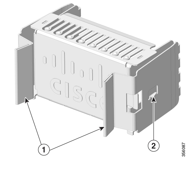
|
1 |
Release handles |
2 |
Retainer clip |
Remove a power supply blank cover
To remove the blank cover from a bay, use the release handles to hold the blank cover (with your thumb and index fingers), squeeze both the handles toward each other and slide the cover out of the bay.
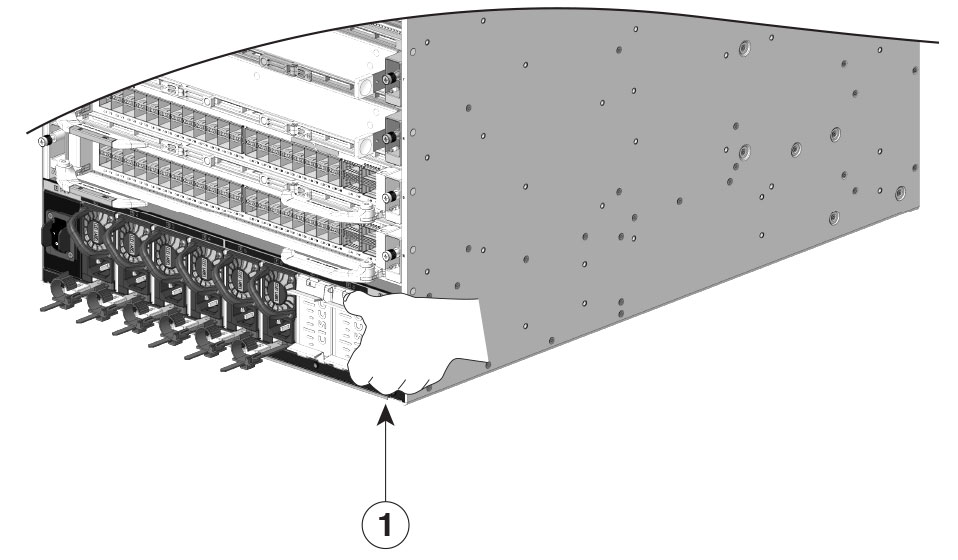
|
1 |
Release handles that are squeezed toward each other |
CautionInstall a power supply blank cover
To install a power supply blank cover, push the blank cover straight and into the bay. You will hear retainer clips snap into place when installed correctly. You can hold the blank cover by the outside edges when you perform this task; alternatively, use the release handles to hold the blank cover.
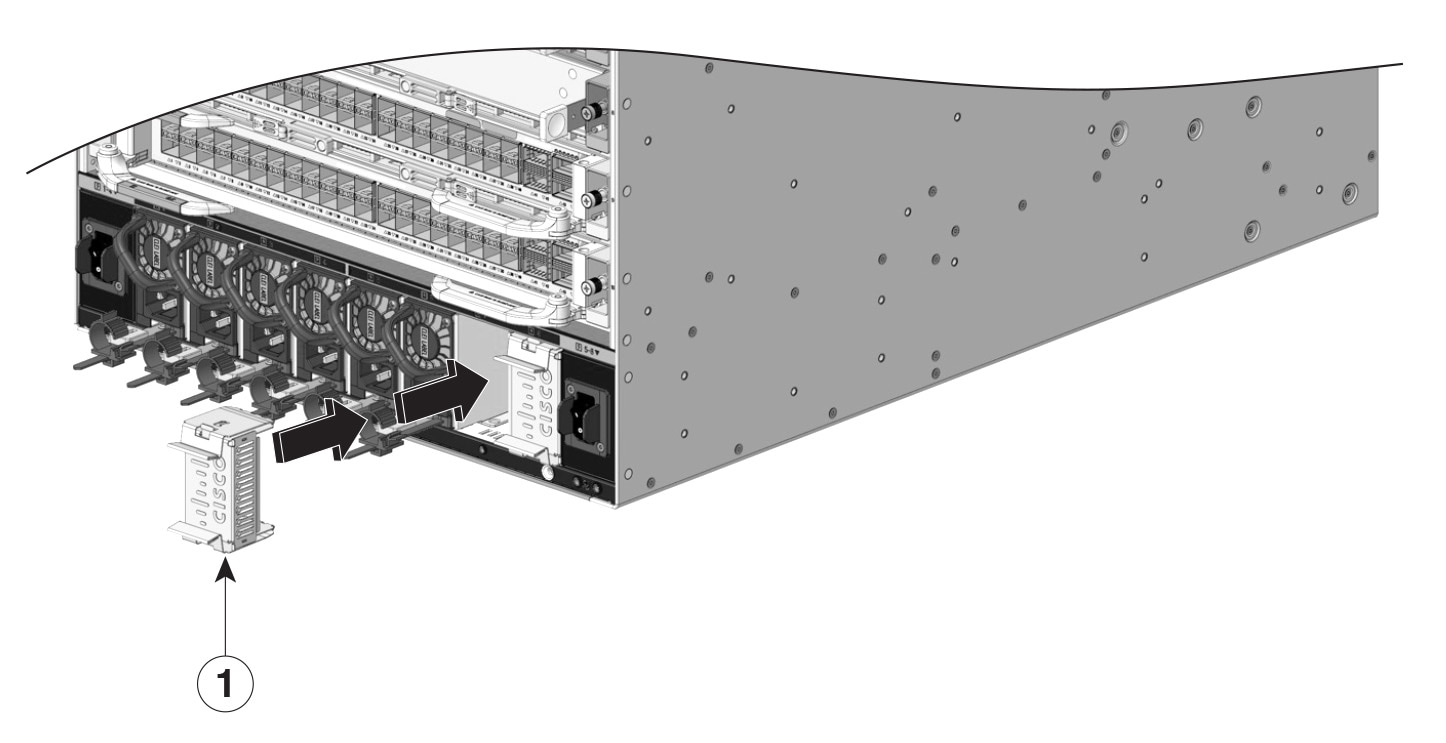
|
1 |
Power supply blank |
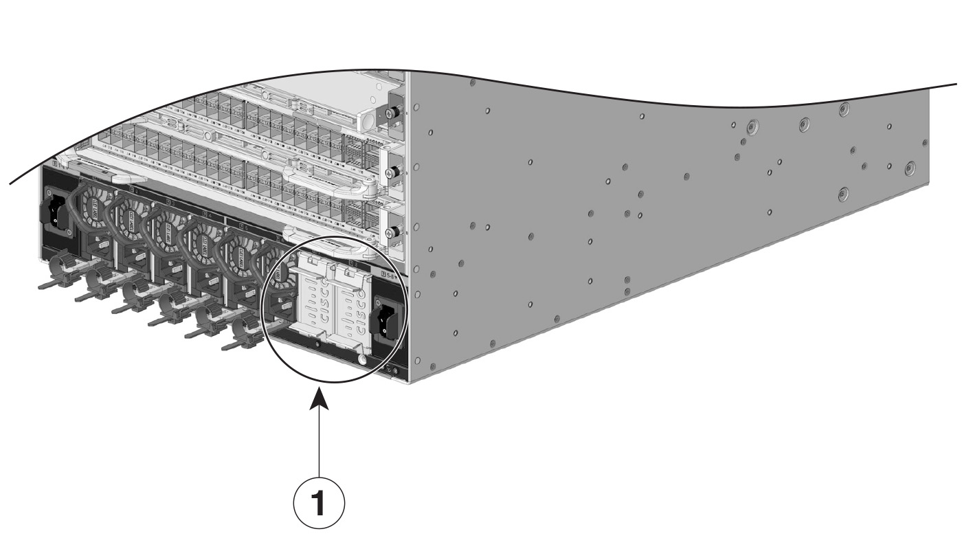
|
1 |
Power supply blanks after installation |
NoteFind the power supply serial number
If you contact Cisco Technical Assistance, you need to know the serial number. These figures show where the serial number is located. You can also use the show version privileged EXEC command to see the serial number.
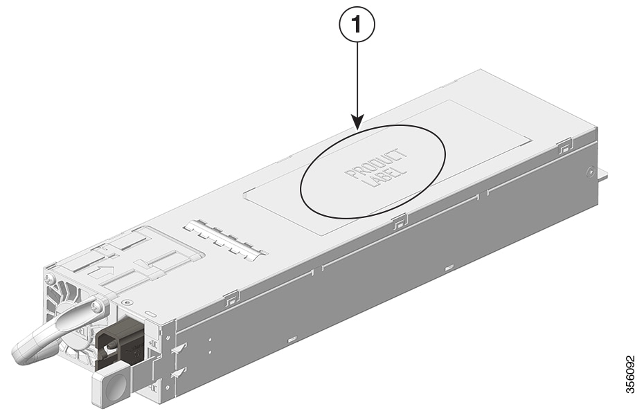
|
1 |
Power supply module serial number |
- |
- |
Verify the power supply installation
Step 1 | Verify the power supply operation by checking the power supply’s front-panel LED. See Power supply module LEDs. |
Step 2 | Check the power supply and system status from the system console by entering show power command in privileged EXEC mode. |
Step 3 | If the LEDs or show power command output indicate a power problem or other system problem. |