Overview of Cisco Catalyst 9600 Series Supervisor Engines
This document describes the features of supported Cisco Catalyst 9600 Series Supervisor Engines and provides information about how to remove or replace a supervisor engine (module) in a chassis.
|
Product ID |
Description |
|---|---|
|
C9600-SUP-1 |
Cisco Catalyst 9600 Series Supervisor Engine 1 |
|
C9600X-SUP-2 |
Cisco Catalyst 9600 Series Supervisor Engine 2 |
|
Compatibility Information |
C9600-SUP-1 |
C9600X-SUP-2 |
|---|---|---|
|
Chassis compatibility |
Supported on Cisco Catalyst 9600 Series 6 Slot Chassis (C9606R). | |
|
Minimum software requirements |
Cisco IOS XE Gibraltar 16.11.1 and later releases. See the Release Notes for Cisco Catalyst 9600 Series Switches document for the latest software release requirements. |
Cisco IOS XE 17.7.1 and later releases. |
|
Chassis slot restrictions |
C9606R: Slots 3 and 4 only (redundant supervisor engines supported). The primary supervisor engine can be installed in either slot. |
|
|
Bandwidth per slot |
2.4 Tbps full-duplex per slot |
6.4 Tbps full-duplex per slot |
|
Memory |
Dynamic Random-Access Memory (DRAM): 16 GB |
Dynamic Random-Access Memory (DRAM): 32 GB |
|
Onboard flash: 16 GB |
Onboard flash: 16 GB |
|
|
Line Card compatibility |
|
|
Features of Cisco Catalyst 9600 Series Supervisor Engine 1 (C9600-SUP-1)
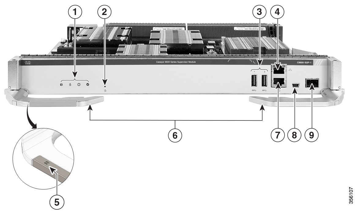
The following figure shows the front view of a Cisco Catalyst 9600 Series Supervisor Engine 1 (C9600-SUP-1), with the major features identified.
|
1 |
Supervisor engine LEDs |
6 |
Ejector levers |
|
2 |
Reset button |
7 |
RJ-45 console port |
|
3 |
USB 3.0 Type A ports |
8 |
USB mini Type B console port |
|
4 |
RJ-45 Ethernet management port |
9 |
10 G SFP+ management port |
|
5 |
RFID embedded on the left ejector lever |
- |
- |
|
Feature |
Icon |
Description |
|---|---|---|
|
USB 3.0 Type A port |
 |
The supervisor engine provides two USB 3.0 Type A ports for external storage and dongles. It supports USB versions 3.0, 2.0, 1.1, and 1.0. |
|
USB mini Type B console port |
 |
This USB port is used as a console port, allowing attachment to PCs that are not equipped with an RS-232 interface. See Console Ports. |
|
10/100/1000 Ethernet Management port (RJ-45 connector) |
 |
The Ethernet management port is a Layer 3 host port to which you can connect a PC. By default, the Ethernet management port is enabled. You can use the Ethernet management port for network management. See Management Ports |
|
Console port (RJ-45 connector) |
|
This is an RS232 serial or console port for system management. See Console Ports |
|
Blue beacon LED |
 |
The blue beacon LED on the front panel of the supervisor engine that allows easy identification of the device . |
|
Reset button |
 |
The reset switch is used to reset and restart a supervisor engine. See Reset Button |
|
10G SFP+ management port |
 |
The supervisor engine has one 10G SFP+ management port. This port requires either small form-factor pluggable (SFP) or SFP+ transceivers. See Management Ports |
|
SATA SSD module slot |
- |
The supervisor module has an M.2 SATA connector that supports SSD local storage for container-based application hosting. This is an optional feature. |
|
Model number |
- |
Supervisor engine model number. |
|
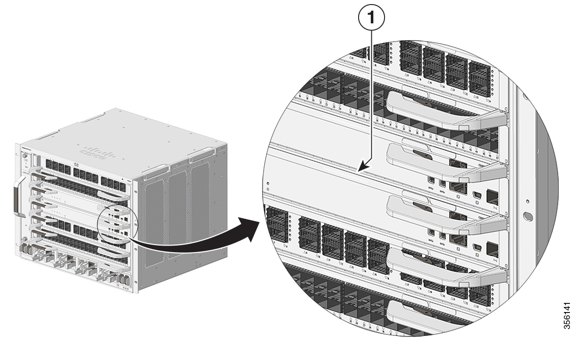
Supervisor slot indicator |
- |
The fan tray front panel indicates the supervisor slots in a chassis. |
Features of Cisco Catalyst 9600 Series Supervisor Engine 2 (C9600X-SUP-2)
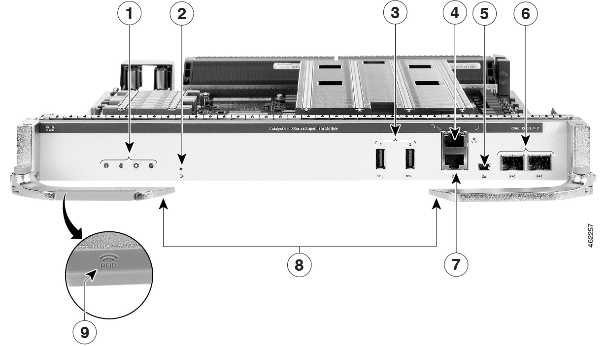
The following figure shows the front view of a Cisco Catalyst 9600 Series Supervisor Engine 2 (C9600X-SUP-2), with the major features identified.
|
1 |
Supervisor engine LEDs |
6 |
10G SFP+ management ports |
|
2 |
Reset button |
7 |
RJ-45 console port |
|
3 |
USB 3.0 Type A ports |
8 |
Ejector levers |
|
4 |
RJ-45 Ethernet management port |
9 |
RFID embedded on the left ejector lever |
|
5 |
USB mini Type B console port |
- |
- |
|
Feature |
Icon |
Description |
|---|---|---|
|
USB 3.0 Type A port |
|
The supervisor engine provides two USB 3.0 Type A ports for external storage and dongles. It supports USB versions 3.0, 2.0, 1.1, and 1.0. |
|
USB mini Type B console port |
|
This USB port is used as a console port, allowing attachment to PCs that are not equipped with an RS-232 interface. See Console Ports. |
|
10/100/1000 Ethernet Management port (RJ-45 connector) |
|
The Ethernet management port is a Layer 3 host port to which you can connect a PC. By default, the Ethernet management port is enabled. You can use the Ethernet management port for network management. See Management Ports |
|
Console port (RJ-45 connector) |
|
This is an RS232 serial or console port for system management. See Console Ports |
|
Blue beacon LED |
|
The blue beacon LED on the front panel of the supervisor engine that allows easy identification of the device . |
|
Reset button |
|
The reset switch is used to reset and restart a supervisor engine. See Reset Button |
|
10G SFP+ management ports |
|
The supervisor engine has two 10G SFP+ management ports. One port is used for management and the other port can be used to connect to any port on the line cards. These two ports only support 10G SFP+ transceivers. See Management Ports |
|
Model number |
- |
Supervisor engine model number. |
|
Supervisor slot indicator |
- |
The fan tray front panel indicates the supervisor slots in a chassis. |
Front Panel Components
The following sections describe the front panel components:
USB 3.0 Type A Port
The USB 3.0 Type A port provides access to external USB flash devices (also known as thumb drives or USB keys). The port supports Cisco USB flash drives with capacities from 64MB to 16GB. USB devices with port densities of 64 MB, 128 MB, 256 MB, 1 GB, 4 GB, 8 GB, and 16 GB are supported. The port provides 2.5 W of power to the device connected to the port.
Cisco IOS software provides standard file system access to the flash device, such as read, write, erase, and copy, as well as the ability to format the flash device with a FAT file system.
Observe these guidelines when using USB flash drives:
-
There must be at least one partition on the USB flash drive. If the drive has more than one partition, only the first partition is visible in the system (Cisco IOS).
-
If you partition the flash drive, we recommend that you use a Linux system to perform this task. This ensures that the first partition is a usable partition when connected to the switch.
Using a Windows or MacBook machine utility to perform this task may result in two partitions on the drive by default (partition for system information + actual usable partition). When such a flash drive is connected to the switch, the system displays only the first system information partition, and not the actual usable partition.
Console Ports
The supervisor module provides two types of console ports on the supervisor module front panel:
-
RJ45 console port: This port provides universal asynchronous receiver/transmitter (UART) support to access the route processor with a serial console running at 9600 baud rate with 8 bits for data, no parity bit, and 1 stop bit.
-
Mini USB 2.0 Type B console port: This port functions as a second console connection to the route processor. The USB console port connection uses a mini USB 2.0 cable. The USB console interface speed is the same as the RJ45 console interface speed.
Only one of the consoles is active at a time. When a USB host (PC) is plugged into the USB console port, the hardware automatically switches over to use the USB console. Only a PC that has the necessary USB console device driver causes the USB console to become active. Plugging in a PC that does not have the USB console driver support does not cause a switchover. When the USB cable is removed, or the PC deactivates the USB connection, or a host is not detected on the USB console, the hardware automatically switches to the RJ45 console interface.
The console port allows you to perform the following functions:
-
Configure the switch from the CLI
-
Monitor network statistics and errors
-
Configure SNMP agent parameters
Management Ports
The Supervisor Module provides two types of management ports, 10/100/1000BASE-T RJ-45 port and 10G SFP+ port. The RJ-45 and SFP+ management ports provide out-of-band (OOB) Ethernet network connectivity, which enables you to use the CLI to manage the switch using its IP address. A management port supports TFTP image downloading, network management, SNMP, Telnet, and SSH connections.
-
SFP+ management port: This port is a fiber port that is referred to as TenGigabitEthernet<slot>/0/<port>. The C9600-SUP-1 module has one SFP+ port that supports 1G and 10G speeds. The C9600X-SUP-2 module has two SFP+ ports in which only one port is used for management. The SFP+ ports on C9600X-SUP-2 support only 10G speed.
-
Ethernet management port: This port is a copper Ethernet port that is referred to as GigabitEthernet0/0( Gi0/0) port. The Ethernet management port supports speed upto 10/100/1000 Mbps and is set to auto-negotiate.
You can use one of these ports depending on the cable and connectors that you are using to connect the management interface to the network. Use only one of these management ports; the switch does not support the use of both management ports. By default, the Ethernet management port is enabled.
Use the management port instead of the console port for network management. A switch cannot route packets from a management port to a network port, and from a network port to a management port. To obtain this, the management interface is automatically placed in a separate routing domain (or VRF domain), called Mgmt-vrf. The devices support out-of-band (OOB) management through Mgmt-vrf, which is used to segment management traffic from the global routing table of the switch.
When managing a switch, connect the PC to the management port of the supervisor engine.
Reset Button
A recessed access button is available on the front panel of the supervisor module to reset and restart the module. Using a pin, press and hold the button inwards for 5 seconds to reset and restart the module.
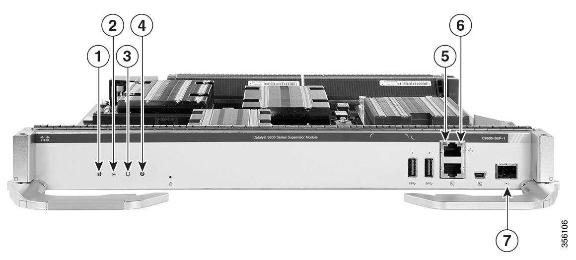
Supervisor Engine LEDs
|
1 |
Status LED |
5 |
Ethernet Management Link Activity LED |
||
|
2 |
Blue Beacon LED |
6 |
Ethernet Management Link Status LED |
||
|
3 |
System LED |
7 |
SFP+ Management Port LED
|
||
|
4 |
Active LED |
- |
- |
|
LED Type |
LED Position or Color |
Meaning |
|---|---|---|
 Status |
Green |
Indicates that all the diagnostic tests have passed after image booting. |
|
Amber |
Indicates a major environmental warning. |
|
|
Red |
Indicates a fault in the module due to a parity error, failed diagnostic tests, or hardware failure. |
|
|
Off |
Indicates that the supervisor module is disabled or is not powered up. |
|
|
Blue Beacon |
Solid blue |
Identifies the supervisor module receiving the beacon signal. |
 System |
Green |
Indicates that the environmental monitors are normal. |
|
Amber |
Indicates a minor fault such as partial power supply or fan failure. |
|
|
Red |
Indicates a major fault, for example, situations where the temperature of the supervisor module exceeds the critical threshold. |
|
 Active |
Green |
Indicates that the supervisor module is operational and is functioning as the active supervisor (in redundant supervisor module configurations). |
|
Amber |
Indicates one of the following:
|
|
|
Blinking Amber |
Indicates Graceful Insertion and Removal (GIR) of the module. |
|
 Management Port Link Activity LED |
Blinking green |
Indicates link activity. |
|
Green |
Indicates that the port is up, but there is no link activity. |
|
|
Amber |
Indicates that the port is administratively shut down. |
|
|
Off |
Indicates that the port is not connected or is down. |
|
|
Management Port Link Status LED |
Green |
Indicates that the port and the link are active. |
|
Off |
Indicates that the port is not connected or is down. |
|
|
SFP+ Management Port LED |
Green |
Indicates that the ports are active. |
|
Amber |
Indicates that the port is administratively shut down. |
|
|
Off |
Indicates one of the following:
|
Preparing for Installation and Removal of a Supervisor Engine
Safety Warnings
Safety warnings appear throughout this publication in procedures that may harm you if you perform them incorrectly. A warning symbol precedes each warning statement. The warnings below are general warnings that are applicable to the entire publication.
 Warning |
IMPORTANT SAFETY INSTRUCTIONS Before you work on any equipment, be aware of the hazards involved with electrical circuitry and be familiar with standard practices for preventing accidents. Read the installation instructions before using, installing, or connecting the system to the power source. Use the statement number at the beginning of each warning statement to locate its translation in the translated safety warnings for this device. SAVE THESE INSTRUCTIONS  |
 Note |
You are strongly advised to read the safety instruction before using the product. https://www.cisco.com/web/JP/techdoc/pldoc/pldoc.html When installing the product, use the provided or designated connection cables/power cables/AC adapters. 〈製品使用における安全上の注意〉 www.cisco.com/web/JP/techdoc/index.html 接続ケーブル、電源コードセット、ACアダプタ、バッテリなどの部品は、必ず添付品または 指定品をご使用ください。添付品・指定品以外をご使用になると故障や動作不良、火災の 原因となります。また、電源コードセットは弊社が指定する製品以外の電気機器には使用 できないためご注意ください。 |
Warning |
To reduce the risk of electric shock, connect the chassis of this equipment to permanent earth ground during normal use. |
Warning |
This product is a Class 1 laser product. |
Warning |
This unit is intended for installation in restricted access areas. Only skilled, instructed, or qualified personnel can access a restricted access area. |
Warning |
Blank faceplates and cover panels serve three important functions: they reduce the risk of electric shock and fire, they contain electromagnetic interference (EMI) that might disrupt other equipment, and they direct the flow of cooling air through the chassis. Do not operate the system unless all cards, faceplates, front covers, and rear covers are in place. |
Warning |
To reduce the risk of bodily injury, mount the chassis on a rack that is permanently affixed to the building. |
Warning |
Invisible laser radiation is present. Do not expose to users of telescopic optics. This applies to Class 1/1M laser products.  |
Warning |
Invisible laser radiation may be emitted from the end of the unterminated fiber cable or connector. Do not view directly with optical instruments. Viewing the laser output with certain optical instruments, for example, eye loupes, magnifiers, and microscopes, within a distance of 100 mm, may pose an eye hazard. |
Warning |
Only a skilled person should be allowed to install, replace, or service this equipment. See statement 1089 for the definition of a skilled person. |
Warning |
To reduce risk of electric shock or fire, installation of the equipment must comply with local and national electrical codes. |
Note |
An instructed person is someone who has been instructed and trained by a skilled person and takes the necessary precautions when working with equipment. A skilled person or qualified personnel is someone who has training or experience in the equipment technology and understands potential hazards when working with equipment. |
Warning |
Only an instructed person or skilled person should be allowed to install, replace, or service this equipment. See statement 1089 for the definition of an instructed or skilled person. |
Warning |
High touch/leakage current—Permanently connected protective earth ground is essential before connecting to the system power supply. |
Warning |
Ultimate disposal of this product should be handled according to all national laws and regulations. |
Preventing ESD Damage
ESD damage might occur when modules or other FRUs are improperly handled, resulting in intermittent or complete failure of the modules or FRUs. Modules consist of printed circuit boards that are fixed in metal carriers. EMI shielding and connectors are integral components of a carrier. Although the metal carrier helps to protect the board from ESD, always use an ESD-grounding strap when handling modules. To prevent ESD damage, follow these guidelines:
-
Always use an ESD wrist or ankle strap and ensure that it makes good skin contact.
-
Connect the equipment end of the strap to an unfinished chassis surface.
-
When installing a component, use an available ejector lever to properly seat the bus connectors in the backplane or midplane. These devices prevent accidental removal, provide proper grounding for the system, and help to ensure that bus connectors are properly seated.
-
When removing a component, use an available ejector lever to release the bus connectors from the backplane or midplane.
-
Handle carriers by available handles or edges only; avoid touching the printed circuit boards or connectors.
-
Place a removed component board-side-up on an antistatic surface or in a static-shielding container. If you plan to return the component to the factory, immediately place it in a static-shielding container.
-
Avoid contact between the printed circuit boards and clothing. The wrist strap only protects components from ESD voltages on the body; ESD voltages on clothing can still cause damage.
-
Never attempt to remove the printed circuit board from the metal carrier.
Tools Required
You will need these tools to install or remove supervisor engines and line cards:
-
Your own ESD-prevention equipment or the disposable grounding wrist strap included with all upgrade kits, FRUs, and spares.
-
Antistatic mat or antistatic bag
Installing and Removing Supervisor Engines
The following sections provide information about how to install or remove a supervisor engine.
Installing a Supervisor Engine
Warning |
Hazardous voltage or energy is present on the backplane when the system is operating. Use caution when servicing. Statement 1034 |
 Caution |
To prevent ESD damage, handle supervisor engines by the carrier edges only. |
Before you begin
-
Verify that both the supervisor modules in a redundant configuration are of the same type. You cannot use C9600X-SUP-2 and C9600-SUP-1 modules together in a chassis.
-
Verify chassis slot restrictions.
-
Ensure that you have enough clearance to accommodate the interface equipment that you will connect directly to the supervisor engine ports.
Procedure
|
Step 1 |
Take the necessary precautions to prevent ESD damage. Wear a grounded ESD wrist strap while handling the modules, and keep them in ESD-protective bags when they are not installed in a chassis. |
||||||||
|
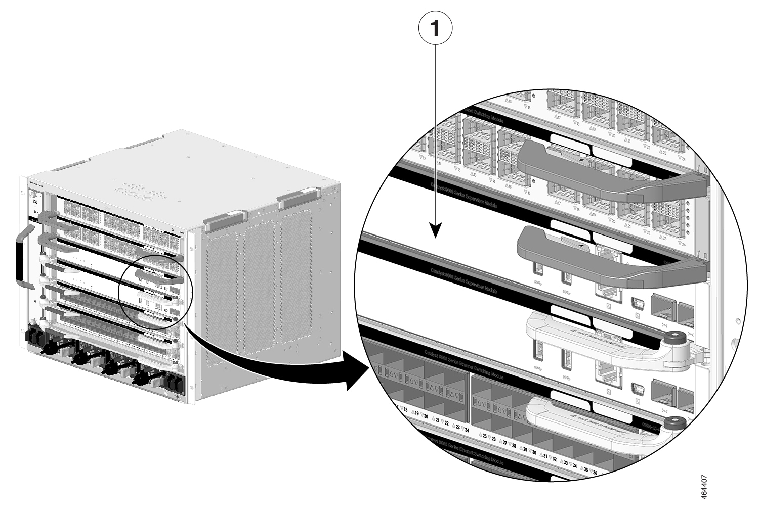
Step 2 |
Remove the slot blank cover (C9606-SLOT-BLANK=) if present, by squeezing the release handles towards each other (with your thumb and index fingers) and slide the cover out of the bay. Save it for future use. 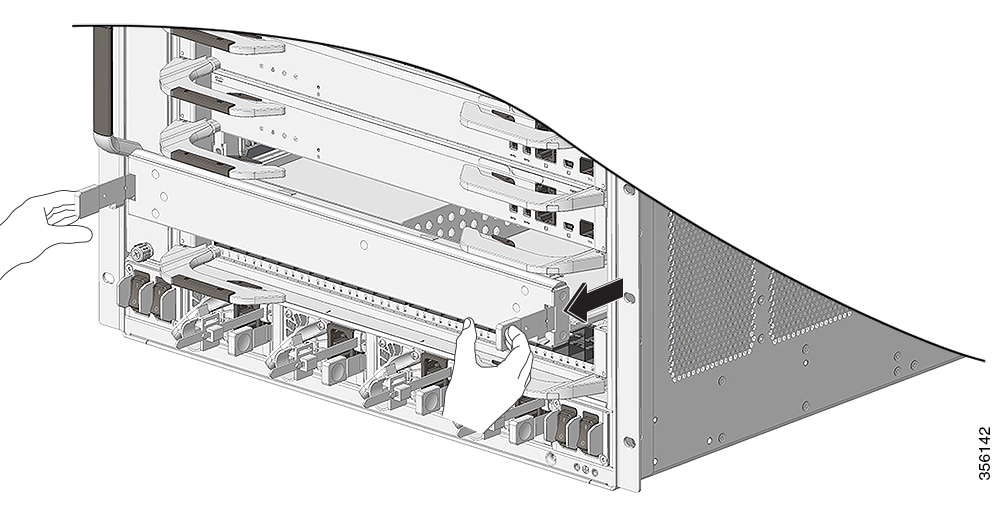 |
||||||||
|
Step 3 |
Remove the new supervisor engine from the shipping packaging. Handle the module using only the module’s metal tray or the front panel. Do not touch the printed circuit board or the connector pins. |
||||||||
|
Step 4 |
Pivot the left and the right ejector levers away from the front of the module and hold them while sliding the module into the slot. |
||||||||
|
Step 5 |
Hold the supervisor engine's front panel with one hand and place your other hand under the carrier to support the module. |
||||||||
|
Step 6 |
Position the new module in the slot. Make sure that you align the sides of the module with the slot guides on each side of the chassis slot.
  |
||||||||
|
Step 7 |
Carefully slide the supervisor engine into the slot. Pivot both the ejector levers inward simultaneously.
When installed correctly:
|
||||||||
|
Step 8 |
Check the status of the module: |
What to do next
Install blank slot cover (C9606-SLOT-BLANK) in empty slots, if any, to maintain consistent air flow through the switch chassis.
Removing a Supervisor Engine
Warning |
Hazardous voltage or energy is present on the backplane when the system is operating. Use caution when servicing. Statement 1034 |
Warning |
Invisible laser radiation may be emitted from disconnected fibers or connectors. Do not stare into beams or view directly with optical instruments. Statement 1051 |
Caution |
To prevent ESD damage, handle the supervisor engine by the carrier edges only. |
Before you begin
-
You will need a slot blank cover (C9606-SLOT-BLANK) if the slot is to remain empty.
-
Install dust plugs into the transceiver’s optical bores if the module is equipped with removable optical transceivers. This prevents possible dust contamination, which can affect port performance.
-
Take necessary precautions to prevent ESD damage. Wear a grounded ESD wrist strap while handling the modules.
Procedure
|
Step 1 |
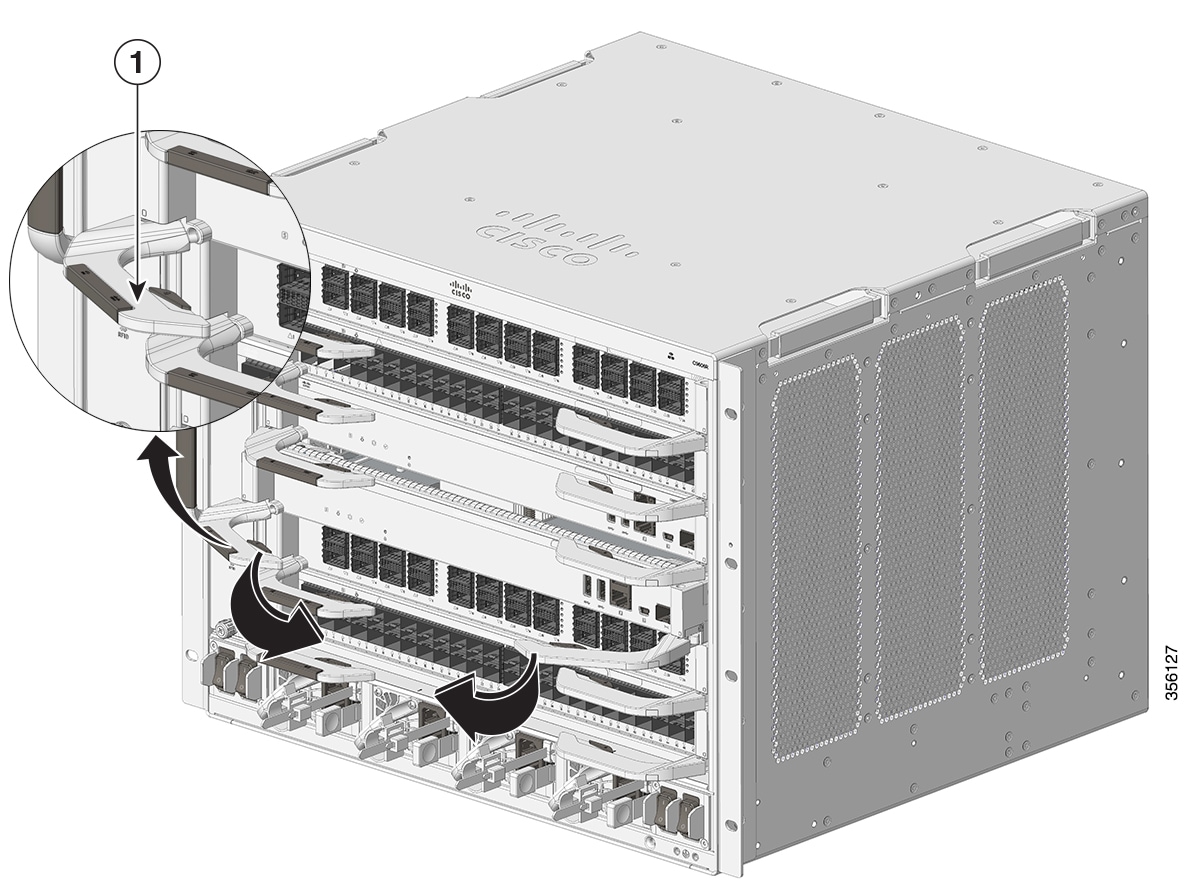
Grasp the left and right ejector levers and slightly push the two module ejector levers in and towards the faceplate. 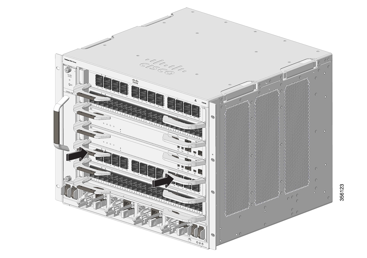 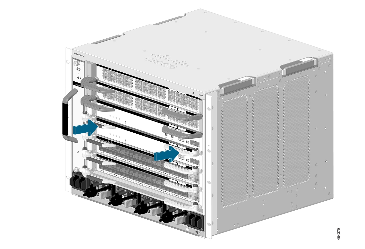 |
||||||||||
|
Step 2 |
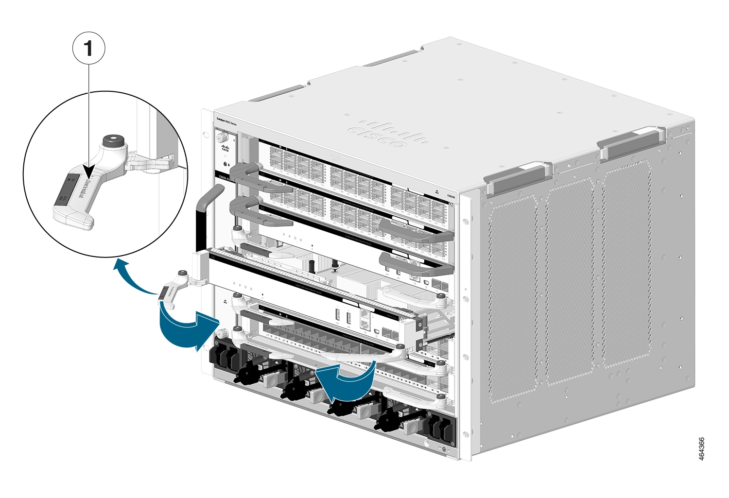
(Applicable only for C9600-SUP-1) Press the ejector buttons on the ejector levers of the module to release the levers from the module.
|
||||||||||
|
Step 3 |
Grasp the left and right ejector levers and simultaneously rotate the levers outward to disengage the supervisor engine from the backplane connector. 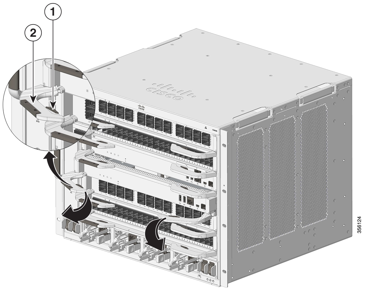
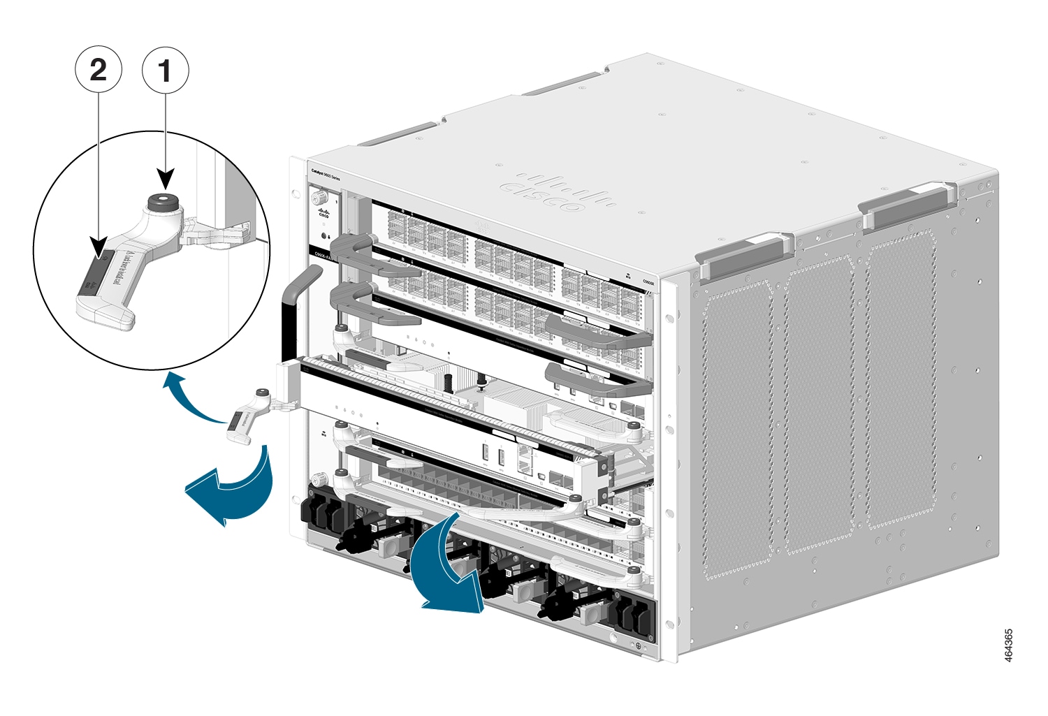
|
||||||||||
|
Step 4 |
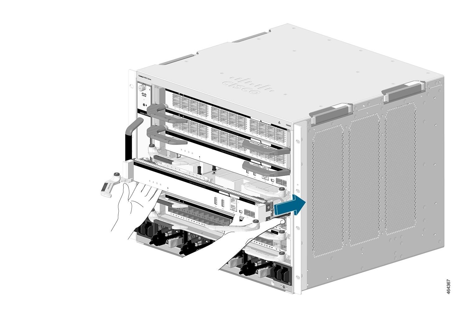
Grasp the front panel of the supervisor engine with one hand and place your other hand under the carrier to support and guide it out of the slot. Do not touch the printed circuit boards or connector pins. |
||||||||||
|
Step 5 |
Carefully slide the supervisor engine straight out of the slot, keeping your other hand under the carrier to guide it. 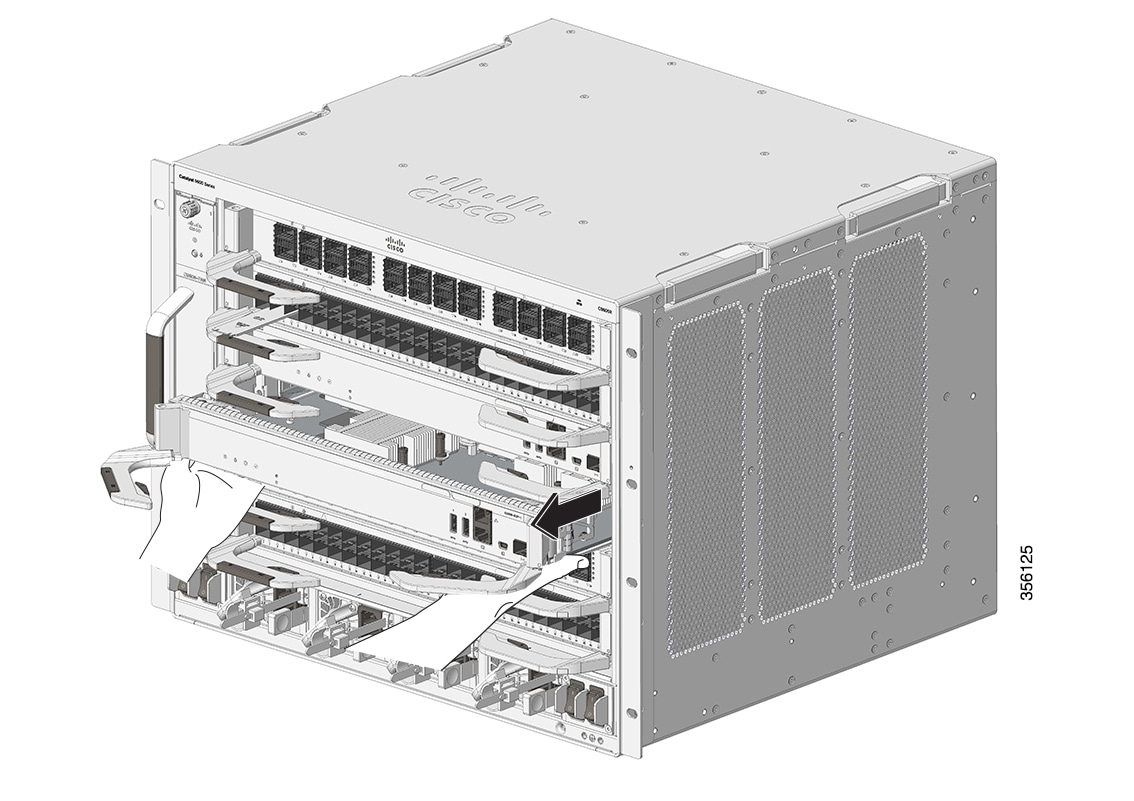 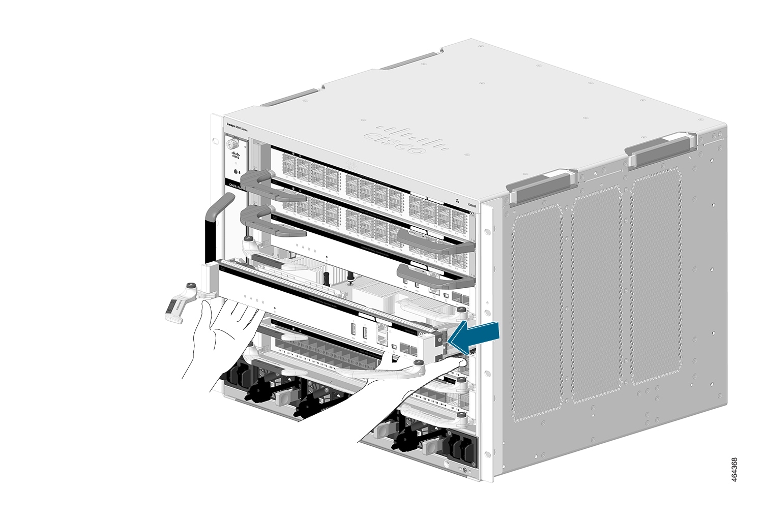 |
||||||||||
|
Step 6 |
Place the supervisor engine on an antistatic mat or in an antistatic bag. |
||||||||||
|
Step 7 |
Install a replacement supervisor engine after a 15-second wait. Alternatively, if the chassis slot should remain empty, install a blank slot cover (C9606-SLOT-BLANK). Blanks should only be removed when installing a module and must be replaced if a module is ever removed. A syslog message is generated every 5 minutes when an empty slot is detected. You must insert a module or a slot blank to avoid chassis overheating.
|
Installing and Removing SATA SSD Modules
The following sections provide information about how to install and remove a SATA SSD module.
Removing an M.2 SATA SSD Module
Before you begin
You should have powered down the system.
Procedure
|
Step 1 |
Take the necessary precautions to prevent ESD damage. Wear a grounded ESD wrist strap while handling the modules, and keep them in ESD-protective bags when they are not installed in a chassis. |
||||||||
|
Step 2 |
Follow the procedure as described in Removing a Supervisor Engine, to remove the supervisor engine from the chassis. |
||||||||
|
Step 3 |
Handle the supervisor engine by the carrier edges and place it on an antistatic mat. |
||||||||
|
Step 4 |
Loosen and remove the mounting screw on the SATA SSD module. |
||||||||
|
Step 5 |
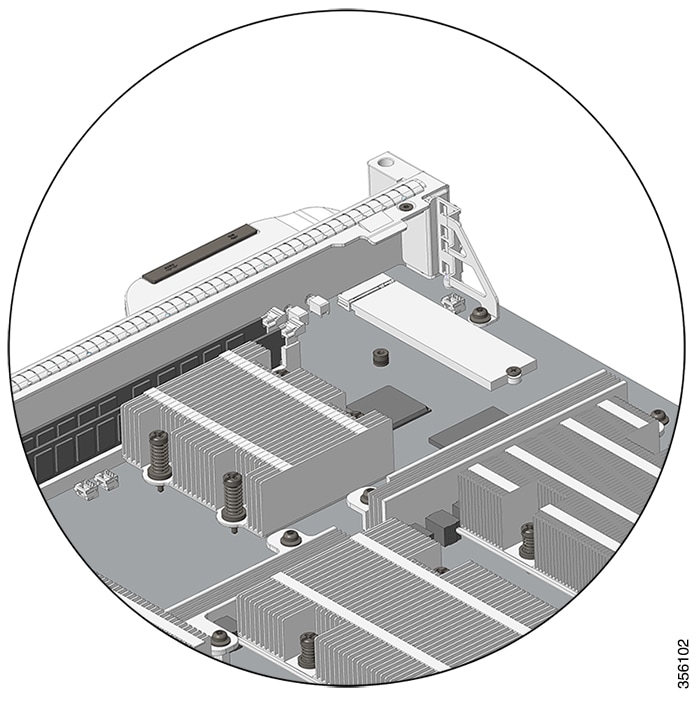
Slide the SATA SSD module out of the connector. 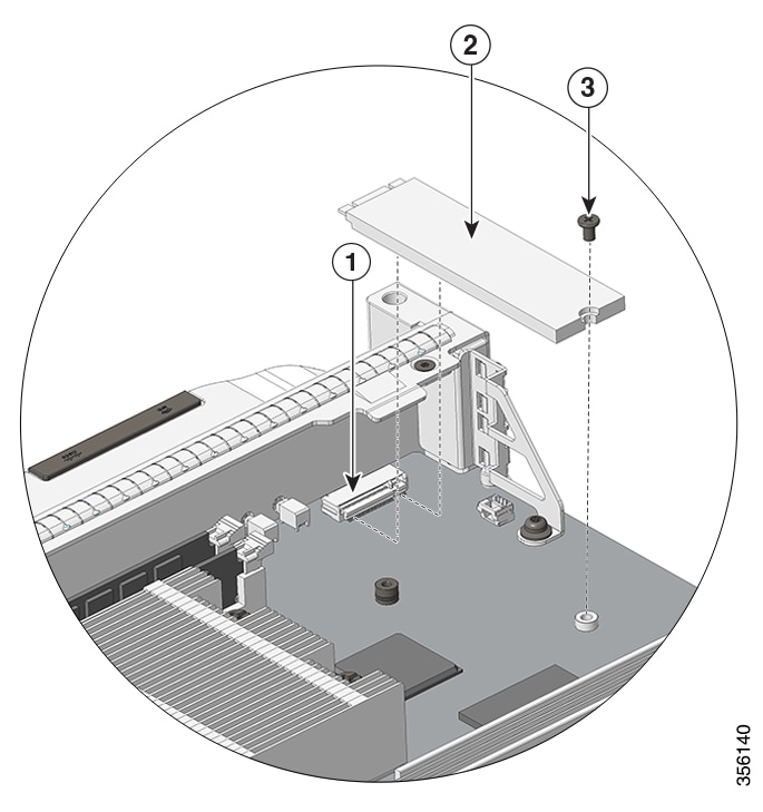
|
Installing an M.2 SATA SSD Module
Before you begin
-
You will need a Philips screwdriver to tighten the mounting screw.
-
Take the necessary precautions to prevent ESD damage. Wear a grounded ESD wrist strap while handling the modules.
Procedure
|
Step 1 |
Loosen and remove the mounting screw on the blank SATA SSD module that is preinstalled on the supervisor engine. 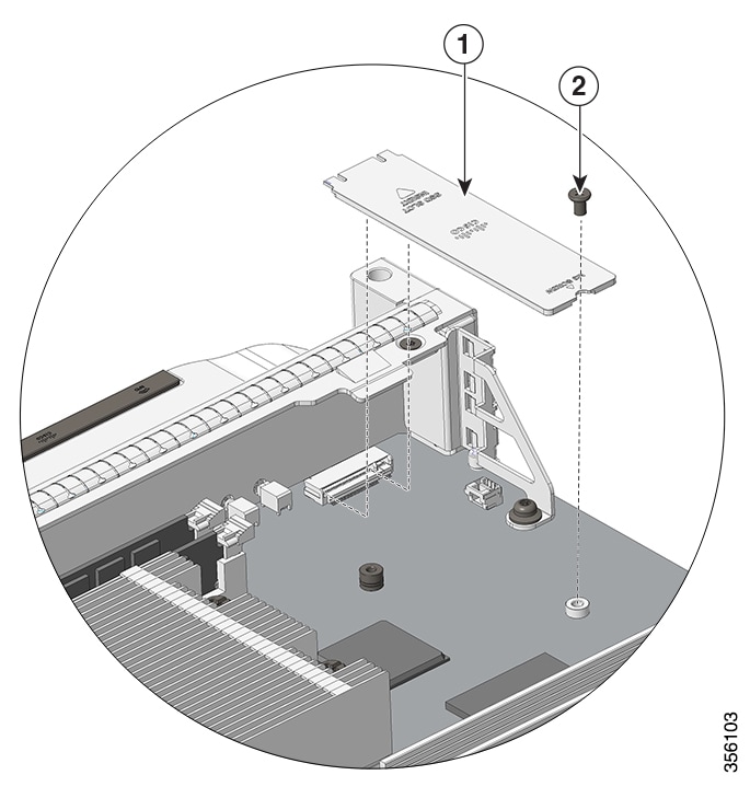
|
||||||||
|
Step 2 |
Remove the new SATA SSD module from the shipping packaging. |
||||||||
|
Step 3 |
Slide the SATA SSD module into the mating connector at a 20-degree angle and then push it down. |
||||||||
|
Step 4 |
Install and tighten the mounting screw.
 |
||||||||
|
Step 5 |
Follow the procedure as described in Installing a Supervisor Engine, to install the supervisor engine. |
||||||||
|
Step 6 |
Power on the chassis. |
 Feedback