LISP VXLAN Fabric Multicast Overview
 Note |
This document assumes that the reader is familiar with the fundamentals of Multicast technology. To understand the basics of Multicast technology, refer IP Multicast Technology Overview. |
LISP VXLAN Fabric supports the following:
-
Layer 2 overlay Broadcast, Unknown Unicast, and Multicast (BUM) traffic to be transported over IP multicast in the underlay network
-
Layer 3 overlay multicast
Layer 2 Overlay Broadcast, Unknown Unicast, and Multicast
Multidestination Layer 2 traffic in a network is typically referred to as broadcast, unknown unicast, and multicast (BUM) traffic. In a LISP VXLAN Fabric, the underlay network forwards the BUM traffic to all the endpoints connected to a common Layer 2 broadcast domain in the VXLAN overlay. The BUM functionality is achieved using the Any Source Multicast (ASM) model in the underlay network. The rendezvous points (RPs) are configured on the border nodes. The RLOC devices, which are the source and receivers, join the shared multicast group that is attached to the RPs. We recommend a dual border topology with the RPs configured on both the border nodes for redundancy.
Note |
Only IPv4 traffic is supported in the underlay. |
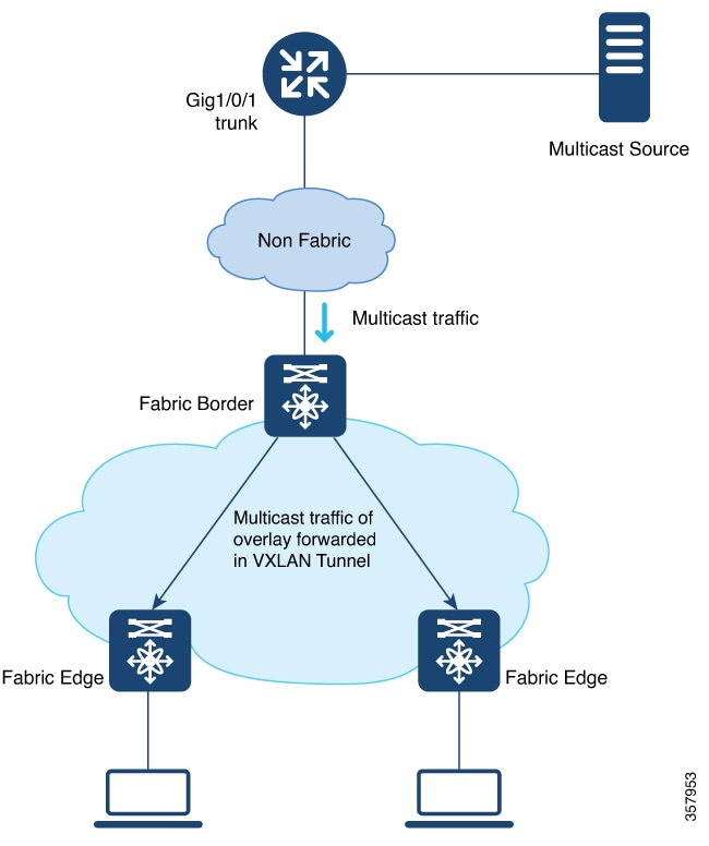
Layer 3 Overlay Multicast
LISP VXLAN Fabric supports both PIM Any Source Multicast (ASM) and PIM Source Specific Multicast (SSM) in the overlay. Layer 3 overlay multicast supports only IPv4 multicast traffic.
The multicast source can either be outside the fabric site or can be in the fabric overlay, connected to the fabric edge node. Multicast receivers can be located outside the fabric site or be directly connected to the fabric edge nodes.
Multicast forwarding in the Layer 3 overlay uses two methods to distribute the traffic through the underlay: Headend Replication and Underlay Multicast. You can configure either Headend Replication or Underlay Multicast in a virtual network. Both cannot be configured together.
Note |
Bidirectional PIM (Bidir-PIM) is not supported in the overlay and the underlay network. |
Any Source Multicast
Any Source Multicast (ASM) is a multicast distribution mode that requires the use of rendezvous points (RPs) to act as a shared root between sources and receivers of multicast data. You can configure a single RP or multiple RPs in the network.
To configure ASM mode in the Layer 3 overlay, you configure the RP selection method, where you indicate the distribution mode and assigns the range of multicast groups.
External RP
External devices can be designated as the RP for the multicast tree in a fabric. To function as an external RP, a device must be a router with PIM enabled. This device is located external to the fabric and is connected to the fabric through one or more border nodes. The External RP address must be reachable in the VRF routing table on the border nodes.
Note |
This release of LISP VXLAN Fabric supports only external RP for overlay multicast traffic. |
Source Specific Multicast
Source Specific Multicast (SSM) creates an optimal path between the multicast source and receiver without the need for a rendezvous point.
You can configure the SSM multicast range that can be supported by the fabric.
Headend Replication
Headend replication is performed by the multicast first-hop router. The first fabric node (FHR) that receives the multicast traffic replicates multiple copies of the VXLAN-encapsulated data packet and unicasts a copy to each of the remote fabric edge nodes where the multicast receivers are located.
The advantage of headend replication is that it does not require multicast in the underlay network to transport the overlay multicast packets. However, it can create a high overhead on the FHRs and result in high bandwidth and CPU utilization.
Underlay Multicast
Underlay multicast works by performing multicast-in-multicast encapsulation. The multicast packets in the overlay network are transported as multicast in the underlay. The load of packet replication is shared across all the devices in the underlay network. To support underlay multicast, the FHRs, Last Hop Routers (LHRs), and all network infrastructure between them must be enabled for multicast. PIM SSM is used in the underlay for multicast transport.

Layer 3 Overlay Multicast Support in LISP VXLAN Fabric
The following multicast methods are supported in this release of LISP VXLAN Fabric:
Layer 3 Overlay Multicast
-
SSM with Underlay Multicast
-
SSM with Headend Replication
-
ASM with Underlay Multicast, External Rendezvous Point
-
ASM with Headend Replication, External Rendezvous Point
 Feedback