Configuring a Multi-Site Remote Border

Configure a multi-site remote border if you require a centralized gateway for a subset of the Virtual Networks (VNs) across multiple fabric sites. The traffic for those VNs will egress the fabric from the multi-site remote border at the central site.

This section describes how to configure a multi-site remote border.

Multi-Site Remote Border

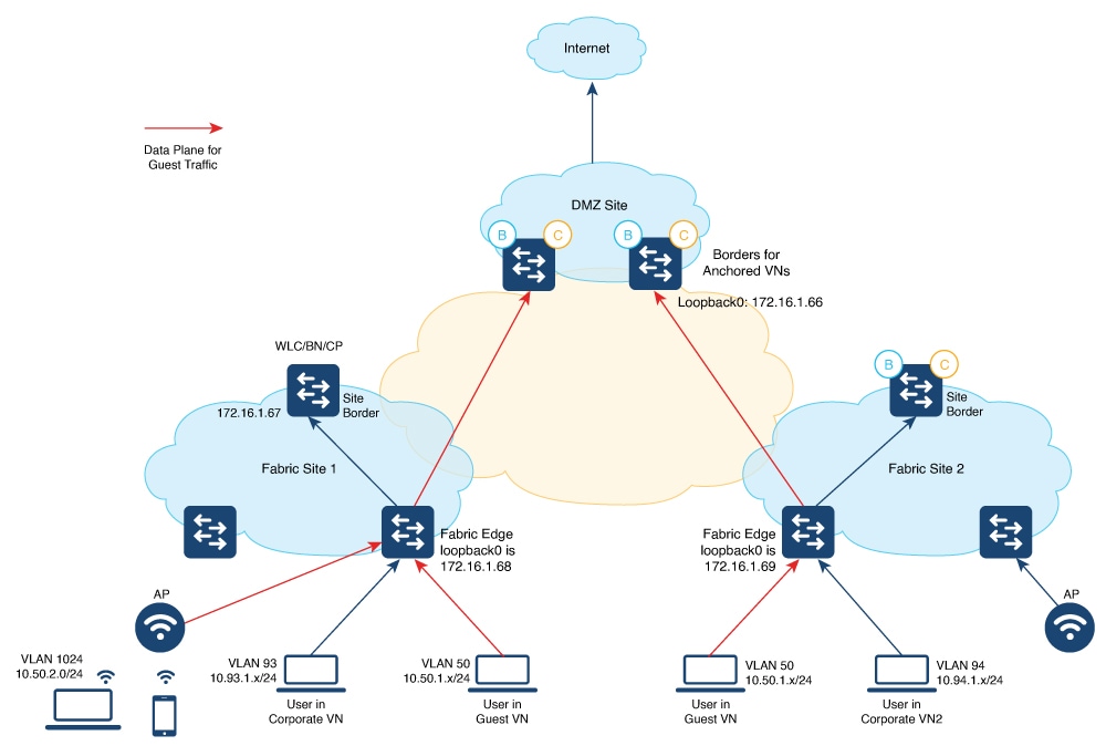
A multi-site remote border enables the fabric network to isolate untrusted traffic to a central location like a firewall or a DMZ (demilitarized zone). For example, if the network has a guest virtual network (VN) that is stretched across multiple sites, all the guest traffic can be tunneled to a remote border at the DMZ, thus isolating the guest traffic from the enterprise traffic.

In a multi-site network deployment, you can designate a common border (multi-site remote border) to route the traffic to and from a particular VN that is stretched across multiple sites. This allows you to deploy a VN across multiple fabric sites but have a single subnet across all these sites. Preserving the subnets across multiple fabric sites helps in conserving the IP address space.

Here are some common terms that are used in the context of a multi-site remote border:

Anchor Virtual Network (VN): A virtual network that exists across multiple fabric sites in a network. The associated IP subnet and segment are common across these multiple sites.

Anchor Site: The fabric site that hosts the common border and control plane for an Anchor VN. Anchor Site handles the ingress and egress traffic for the Anchor VN.

Anchoring Sites: Fabric sites other than the Anchor Site where the Anchor VN is deployed.

Anchor Border Node or Multi-Site Remote Border: The fabric border node at the Anchor Site that provides the ingress and egress location for traffic to and from the Anchor VN.

Anchor Control Plane Node: The fabric control plane node at the Anchor Site that accepts registrations and responds to requests for endpoints in the Anchor VN.

A Use Case for a Multi-Site Remote Border

Different users and devices in an enterprise network require different levels of access on the network. A guest user connecting to a fabric site can be permitted to access the internet but should not be permitted to access business sensitive data or network resources like shared folders, storage devices, and so on. The guest users connecting to multiple fabric sites in an enterprise network must be handled in a secure and reliable manner.

In a typical case, an endpoint (which could be a guest user) in a fabric site is assigned an Endpoint Identifier (EID) address from the local EID subnet and its traffic is directed through the local border. This adds complexity to the policy enforcement and EID address management for guests across multiple sites. To achieve traffic isolation and better manage the guest traffic, you can direct all the guest traffic to a designated border node which is located in the DMZ site. (A DMZ site provides access to external network like the internet but prevents external users from accessing the resources or data of the fabric network.) The DMZ site will now be the ingress and egress site for traffic to and from the guest VN.

Guidelines for Configuring a Multi-Site Remote Border

  • An Anchor VN can have only one Anchor Site.

  • The path from the fabric edge node of the Anchoring Site to the multi-site remote border should support frames greater than 1500 bytes.

  • We recommend a value of 1250 bytes for the Transmission Control Protocol (TCP) Maximum Segment Size (MSS) on the on the overlay SVI interfaces.

How to Configure a Multi-Site Remote Border

This section shows only the configurations on the Anchor Site and the Anchoring Sites for a multi-site remote border.

Before you begin, provision the fabric sites in the network. For a complete description of the fabric site configurations, refer the earlier chapters of this document.

To anchor a VN and configure a multi-site remote border, do the following:

  • Configure the control plane node at the Anchor Site to act as the map-server and map-resolver for the requests from the Anchor VN.

  • Configure the EID prefixes of the Anchor VN only on the control plane node at the Anchor Site. The control plane node of the Anchoring Sites should not be configured with the EID prefixes of the Anchor VN.

In the following topology, a Guest VN (Anchor VN) is spread across Fabric Site 1 and Fabric Site 2 (Anchoring Sites). Each of these fabric sites has its own control plane node and border nodes. The DMZ site (Anchor Site) has a colocated control plane node and border node (CPB), which is configured as the multi-site remote border.


Note


The following is a snippet of the configurations on the fabric edge nodes and the DMZ control plane node. The snippet shows only the configurations that are required for a multi-site remote border functionality. For complete configurations on the fabric nodes, refer to the earlier chapters in the document.


Colocated Control Plane and Border Node at DMZ site Fabric Edge Nodes at the Local Fabric Site
  • Configure the LISP Site on the DMZ to accept the guest EID prefixes.

  • If you have wireless guests, define a locator set for the wireless controller and configure open passive TCP sockets to listen for incoming connections.

  • Define the Layer 3 instance ID for the guests.

<snip: only the relevant configuration is shown>

router lisp
 locator-table default
 locator-set WLC
  172.16.1.67
  exit-locator-set
 !
 locator default-set rloc_set
 service ipv4
  encapsulation vxlan
  itr map-resolver 172.16.1.66
  etr map-server 172.16.1.66 key 7 auth-key
  etr map-server 172.16.1.66 proxy-reply
  etr
  sgt
  no map-cache away-eids send-map-request
  proxy-etr
  proxy-itr 172.16.1.66
  map-server
  map-resolver
  exit-service-ipv4
 !        
 service ethernet
  itr map-resolver 172.16.1.66
  itr
  etr map-server 172.16.1.66 key 7 auth-key
  etr map-server 172.16.1.66 proxy-reply
  etr
  map-server
  map-resolver
  exit-service-ethernet
 !
 instance-id 4100
  remote-rloc-probe on-route-change
  service ipv4
   eid-table vrf Guest
   database-mapping 10.52.2.8/30 locator-set rloc_set
   route-export site-registrations
   distance site-registrations 250
   map-cache site-registration
   exit-service-ipv4
  !
  exit-instance-id
 !
 map-server session passive-open WLC
 site site_uci
  description mapserver authentication-key auth-key
  eid-record instance-id 4099 0.0.0.0/0 
                               accept-more-specifics 
  eid-record instance-id 4099 10.50.1.0/24 
                               accept-more-specifics 
  eid-record instance-id 4099 ::/0 accept-more-specifics
  eid-record instance-id 4099 2001:DB8:2050::/64 
                               accept-more-specifics 
  eid-record instance-id 16188 any-mac
  eid-record instance-id 4100 0.0.0.0/0
                              accept-more-specifics
  allow-locator-default-etr instance-id 4099 ipv4 
  allow-locator-default-etr instance-id 4099 ipv6 
  exit-site
  !
  ipv4 locator reachability exclude-default
  ipv4 source-locator Loopback0
  exit-router-lisp
 !
		
<snip>

Ensure that you use the same authentication key on the control plane node, fabric edge node, and wireless controller.

<snip: only the relevant configuration is shown>

router lisp
 locator-table default locator-set rloc_set
 IPv4-interface Loopback0 priority 10 weight 10 exit-locator-set
 !
 locator default-set rloc_set service ipv4
 encapsulation vxlan 
  //Control plane is at the local Site
 itr map-resolver 172.16.1.67   
 etr map-server 172.16.1.67 key some-key
 etr map-server 172.16.1.67 proxy-reply etr
 sgt
 proxy-itr 172.16.1.68 exit-service-ipv4
 !
 service ipv6 encapsulation vxlan
  //Control plane is at the local Site
 itr map-resolver 172.16.1.67  
 etr map-server 172.16.1.67 key some-key
 etr map-server 172.16.1.67 proxy-reply etr
 sgt
 proxy-itr 172.16.1.68 exit-service-ipv6
 !
 service ethernet
  //Control plane is at the local Site 
 itr
 itr map-resolver 172.16.1.67   
 etr map-server 172.16.1.67 key some-key 
 etr map-server 172.16.1.67 proxy-reply etr
 exit-service-ethernet
!
//Configurations for the Anchor VN with instance id 4099
instance-id 4099
 remote-rloc-probe on-route-change 
 dynamic-eid AVlan50-IPV4
  database-mapping 10.50.1.0/24 locator-set rloc_set 
  exit-dynamic-eid
 !
 dynamic-eid AVlan50-IPV6
  database-mapping 2001:DB8:2050::/64 locator-set rloc_set  
  exit-dynamic-eid
 !
 service ipv4
 eid-table vrf GuestVN  
 map-cache 0.0.0.0/0 map-request
   //Control plane is at the DMZ Site
 itr map-resolver 172.16.1.66    
 etr map-server 172.16.1.66 key auth-key
 etr map-server 172.16.1.66 proxy-reply 
 etr
 proxy-itr 172.16.1.68 
 exit-service-ipv4
!
service ipv6
eid-table vrf GuestVN
map-cache ::/0 map-request
 // Control plane is at the DMZ Site
itr map-resolver 172.16.1.66   
etr map-server 172.16.1.66 key auth-key
etr map-server 172.16.1.66 proxy-reply etr
proxy-itr 172.16.1.68 exit-service-ipv6
!
exit-instance-id
!

// Associate Guest Layer 2 VNID (16188) with the 
//  control plane node at the DMZ site (172.16.1.66)
instance-id 16188
remote-rloc-probe on-route-change service ethernet
eid-table vlan 50
database-mapping mac locator-set eid_locator
  //Control plane is at the DMZ Site
itr map-resolver 172.16.1.66 
itr
etr map-server 172.16.1.66 key auth-key 
etr map-server 172.16.1.66 proxy-reply 
etr
exit-service-ethernet
!
exit-instance-id
!

//Associate Guest Layer 3 VNID (4100) with the  
// control plane node at the DMZ site (172.16.1.66)

instance-id 4100
  remote-rloc-probe on-route-change
  dynamic-eid guest-wireless-IPV4
   database-mapping 10.50.2.0/24 locator-set rloc_set
   exit-dynamic-eid
  !
  service ipv4
   eid-table vrf Guest
   map-cache 0.0.0.0/0 map-request
    //Control plane is at the DMZ Site
   itr map-resolver 172.16.1.66
   etr map-server 172.16.1.66 key 7 auth-key
   etr map-server 172.16.1.66 proxy-reply
   etr
   use-petr 172.16.1.66
   proxy-itr 192.168.113.1
   exit-service-ipv4
  !
  exit-instance-id
 !
 exit-router-lisp
!
<snip>
Wireless Controller at the Anchoring Site
  • The wireless controller has LISP sessions with both the site control plane and the common control plane at the DMZ site.

  • If you configure a guest SSID and associate it to a guest control plane node, the corresponding instance ID on the fabric edge also should associate with the same control plane node.

<snip: only the relevant configuration is shown>

//Configure the Guest SSID to use the control plane at the DMZ
wireless fabric control-plane anchor-vn-control-plane 
 ip address 172.16.1.66 key 0 auth-key
!
wireless fabric name guest-wireless l2-vnid 16188 control-plane-name anchor-vn-control-plane

//Configure the wireless hosts and APs to use the control plane node at the local Site
wireless fabric control-plane default-control-plane 
 ip address 172.16.1.67 key 0 some-key
!
wireless fabric name AP_VLAN l2-vnid 8188 l3-vnid 4097 ip 192.168.155.0 255.255.255.0 control-plane-name default-control-plane
wireless fabric name wireless-campus l2-vnid 8189 control-plane-name default-control-plane

//Configure the Guest SSID
wlan diy-guest_profile 18 diy-guest
 mac-filtering prof-cts-diy-gu-1f67e529
 no security ft adaptive
 no security wpa
 no security wpa wpa2
 no security wpa wpa2 ciphers aes
 no security wpa akm dot1x
 no shutdown

// Configure a Fabric Profile for the Guests
wireless profile fabric diy-guest_profile
 client-l2-vnid 16188
 description diy-guest_profile

// Configure a Policy Profile for the Guests
wireless profile policy diy-guest_profile
 aaa-override
 no central dhcp
 no central switching
 description diy-guest_profile
 dhcp-tlv-caching
 exclusionlist timeout 180
 fabric diy-guest_profile
 http-tlv-caching
 nac
 service-policy input silver-up
 service-policy output silver
 no shutdown

// Create a Policy Tag to map the WLAN Profile to the Policy Profile
wireless tag policy wireless-policy-tag-guest
wlan diy-guest_profile policy diy-guest_profile

<snip>

Verify Multi-Site Remote Border Configuration

Use the following show commands to verify the Multi-Site Remote Border configuration.

To see the LISP sessions that are established by the wireless controller, use the show lisp session command on the wireless controller.

wlc# show lisp session 

Sessions for VRF default, total: 6, established: 4
Peer                 State      Up/Down        In/Out    Users
172.16.1.69:19360  Up         00:55:21       15/35     7
172.16.1.67:4342   Up         01:44:58       51/9      7
172.16.1.67:52937  Up         01:44:58        9/51     4
172.16.1.67:63963  Up         01:44:41        0/11     1
wlc#

To see the wireless fabric status and verify that the guest traffic is controlled at the Anchor Site, use the show wireless fabric summary command on the wireless controller.

wlc# show wireless fabric summary 

Fabric Status      : Enabled


Control-plane: 
Name                             IP-address        Key                              Status
--------------------------------------------------------------------------------------------
anchor-vn-control-plane          192.168.102.1     7fb28b01b3e049ed                 Up   
default-control-plane            192.168.223.1     fbe1110d55b643cc                 Up   


Fabric VNID Mapping:
  Name               L2-VNID        L3-VNID        IP Address             Subnet        Control plane name
----------------------------------------------------------------------------------------------------------------------
  AP_VLAN             8188           4097           192.168.155.0       255.255.255.0    default-control-plane            
  guest-wireless      16188          0                                  0.0.0.0          anchor-vn-control-plane              
  wireless-campus     8189           0                                  0.0.0.0          default-control-plane       

To see the LISP sessions that are established by the fabric edge node at the local site, use the show lisp session command on the fabric edge node.

The command output shows that LISP sessions are established with the control plane node at the local fabric site as well as with the control plane node at the Anchor Site.

fabricEdge# show lisp session 

Sessions for VRF default, total: 2, established: 2
Peer                 State      Up/Down        In/Out    Users
172.16.1.66:4342   Up         01:09:59       46/27     5
172.16.1.67:4342   Up         01:10:00       35/15     13
fabricEdge#