Wireless Support in a LISP VXLAN Fabric
A LISP VXLAN fabric supports the wireless infrastructure in the these modes: Over-the-Top Centralized Wireless and Fabric-Enabled Wireless.
Over-the-Top Centralized Wireless
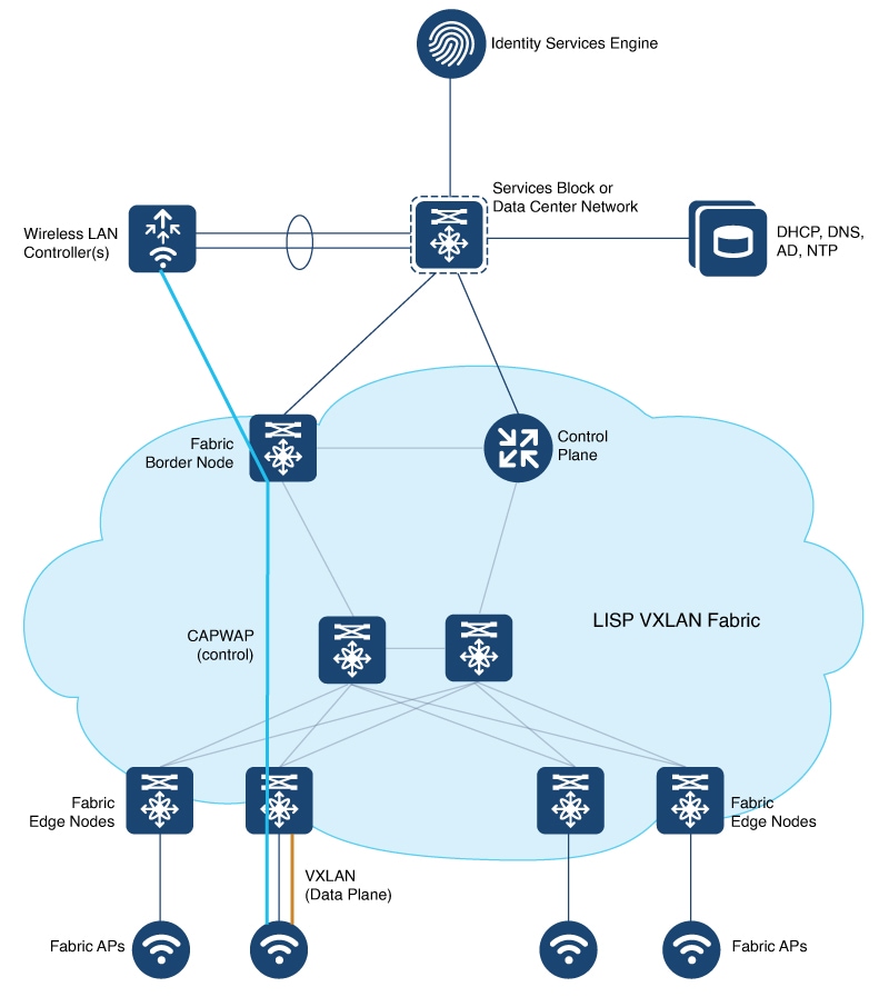
In an over-the-top (OTT) centralized wireless deployment, traditional wireless client traffic is encapsulated in Control and Provisioning of Wireless Access Points (CAPWAP) at the access point. The CAPWAP data is encapsulated in VXLAN at the fabric edge node, and forwarded to the fabric border node. At the border node, the VXLAN encapsulation is removed and the CAPWAP data traffic is forwarded to the wireless controller.
The CAPWAP tunnel between wireless controller and an AP traverses the campus backbone network, using the wired fabric as a transport medium.
OTT wireless deployment is suitable when you are migrating from a traditional network to a LISP VXLAN fabric network, wherein you might want to first migrate the wired infrastructure and plan wireless integration at a later time.

Consider the following before you deploy OTT centralized wireless in your LISP VXLAN fabric.
-
Wireless controller is located external to the fabric.
-
APs are connected to the fabric edge node and are located in the default instance in the fabric overlay. The APs are registered with the control plane node as wired clients.
-
After an AP gets an IP address from DHCP, it joins the wireless controller through CAPWAP tunnel. For information on AP connectivity to wireless controller, refer to Cisco Wireless Controller Configuration Guide.
-
Wireless SSID is mapped to the VLAN or subnet at wireless controller using dynamic interfaces.
-
Wireless clients are authenticated and onboarded by the wireless controller.
-
A network device that is located upstream of the border advertises the wireless network to the fabric border.
-
Communication between a wired host in the fabric and a wireless client outside fabric occurs through the fabric border.
Configuring OTT Centralized Wireless
This task describes only the fabric configurations that are required to enable OTT wireless, assuming that the wireless infrastructure is already functioning in the traditional way.
Before you begin
-
Ensure that you have configured the control plane node, border node, and fabric edge node in a LISP VXLAN fabric for wired clients. For configuration information, refer to the earlier chapters in this document.
-
Ensure that there is a specific subnet reachability in the underlay (global routing table) for the wireless controller subnet at the access layer. This is required for the access points to connect to the wireless controller.
Procedure
|
Step 1 |
On the fabric edge node, configure the switched virtual interface (SVI) for the AP VLAN. Example:The same SVI is present on every fabric edge node, with the same Virtual IP address and MAC address. This makes it a default gateway for all traffic from the APs. |
|
Step 2 |
Configure Layer 3 VNI and Layer 2 VNI for the AP VLAN. An AP is placed in the global routing table which has a LISP instance ID (VNI) attached. In this example, Layer 3 instance ID for the global routing table is 4097 and the corresponding Layer 2 instance id is 8189. Example: |
|
Step 3 |
On the wireless controller, map the wireless SSID to the wireless client VLAN or subnet. Example: |
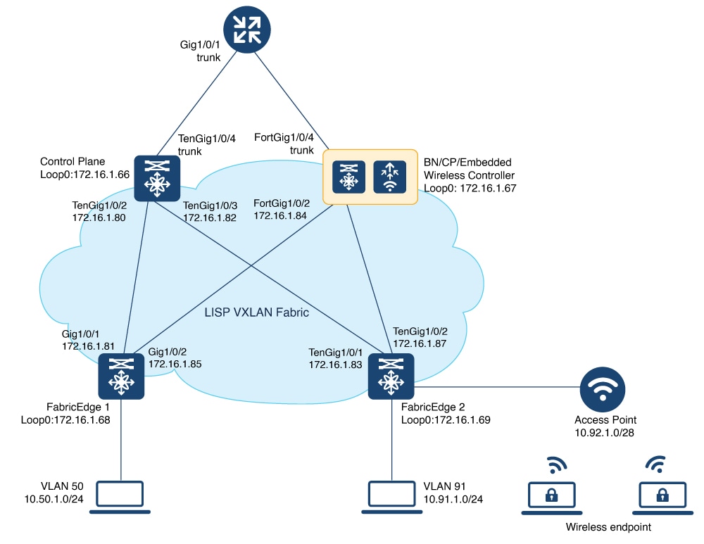
Fabric-Enabled Wireless
A fabric-enabled wireless network integrates the wireless infrastructure with the wired fabric network. In a fabric with integrated wired and wireless, a single infrastructure for wired and wireless connectivity provides a uniform experience by having a common overlay for both the wired and wireless hosts. Wireless users get all the advantages of a fabric such as enhanced security with uniform policy application, data plane optimization, and operational simplicity.
-
Wireless controller controls and manages all wireless functions. It interacts with the fabric control plane to notify the control plane node of all the wireless client joins, roams and disconnects.
-
Fabric control plane node maintains the endpoint locator database for both the wired and wireless clients. It resolves the lookup requests from the fabric edge nodes to locate the endpoints. The control plane node notifies the fabric edge and border nodes about the wireless client mobility and RLOC information.
-
Fabric APs connect directly to the fabric edge nodes. A fabric AP establishes a Control and Provisioning of Wireless Access Points (CAPWAP) tunnel to the fabric wireless controller and connects as local-mode AP. It applies all wireless specific features like SSID policies, AVC, QoS, so on, to the wireless endpoints.
-
Fabric edge node onboards an AP into the fabric. It serves as a single Layer 3 default gateway for all the connected endpoints.
-
Control plane traffic between the fabric APs and the fabric wireless controller is through the CAPWAP tunnel.
-
For the data plane, a fabric AP establishes a VXLAN tunnel to the fabric edge node. Wireless data traffic traverses through this tunnel to reach the fabric edge node. The fabric edge node terminates the AP VXLAN tunnel and the client data traffic is placed on the wired fabric network. The VXLAN tunnel between the fabric AP and the fabric edge node carries the segmentation and policy information to and from the fabric edge node.
 Note |
The rest of the document describes the fabric-enabled wireless mode of operation. |
 Feedback