Connector Specifications
10/100/1000 Ports (Including PoE)
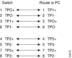
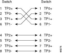
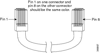
All 10/100/1000 ports use standard RJ-45 connectors and Ethernet pinouts.
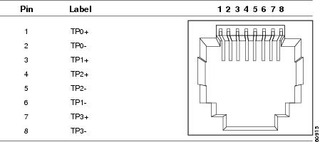
Module Connectors



The documentation set for this product strives to use bias-free language. For the purposes of this documentation set, bias-free is defined as language that does not imply discrimination based on age, disability, gender, racial identity, ethnic identity, sexual orientation, socioeconomic status, and intersectionality. Exceptions may be present in the documentation due to language that is hardcoded in the user interfaces of the product software, language used based on RFP documentation, or language that is used by a referenced third-party product. Learn more about how Cisco is using Inclusive Language.
All 10/100/1000 ports use standard RJ-45 connectors and Ethernet pinouts.


The switch has two console ports: a USB 5-pin mini-Type B port on the front panel and an RJ-45 console port on the rear panel.

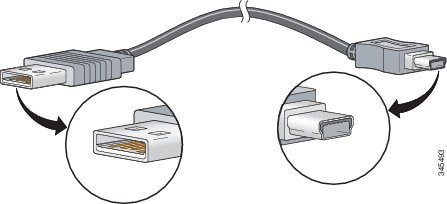
The USB console port uses a USB Type A to 5-pin mini-Type B cable. The USB Type A-to-USB mini-Type B cable is not supplied. You can order an accessory kit (part number 800-33434) that contains this cable.
The RJ-45 console port uses an 8-pin RJ-45 connection. The supplied RJ-45-to-DB-9 adapter cable is used to connect the console port of the switch to a console PC. You need to provide a RJ-45-to-DB-25 female DTE adapter if you want to connect the switch console port to a terminal.
You can order these StackWise cables (nonhalogen) from your Cisco sales representative:
STACK-T1-50CM= (0.5-meter cable)
STACK-T1-1M= (1-meter cable)
STACK-T1-3M= (3-meter cable)
|
Cable Part Number |
Cable Length |
Minimum Bend Radius |
Minimum Coiled Diameter |
|---|---|---|---|
|
STACK-T1-50CM |
1.64 feet (0.5 m) |
2.60 in. (66 mm) |
5.20 in. (132 mm) |
|
STACK-T1-1M |
3.28 feet (1.0 m) |
2.60 in. (66 mm) |
5.20 in. (132 mm) |
|
STACK-T1-3M |
9.84 feet (3.0 m) |
3.58 in. (91 mm) |
7.17 in. (182 mm) |
|
STACK-T2-50CM |
1.64 feet (0.5 m) |
2.60 in. (66 mm) |
5.20 in. (132 mm) |
|
STACK-T2-1M |
3.28 feet (1.0 m) |
2.60 in. (66 mm) |
5.20 in. (132 mm) |
|
STACK-T2-3M |
9.84 feet (3.0 m) |
3.58 in. (91 mm) |
7.17 in. (182 mm) |
For cabling specifications, refer to the following notes:
Cisco Catalyst 2960-X and 2960-XR Switches now support QSFP-4X10G-AOC5M, the 40GQSFP to four 10G SFP+ direct attach breakout Active Optical cable assembly.
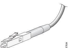
Each port must match the wavelength specifications on the other end of the cable, and the cable must not exceed the stipulated cable length. Copper 1000BASE-T SFP module transceivers use standard four twisted-pair, Category 5 cable at lengths up to 328 feet (100 meters).
Cisco QSFP to SFP or SFP+ Adapter (QSA) is a pluggable adapter that converts a QSFP port in to an SFP or SFP+ port. You can connect one of the following SFP+ or SFP module or an SFP+ copper.
The following is the list of Cisco SFP or SFP+ transceiver modules that are currently supported.
Cisco SFP-10G-SR - Cisco 10GBASE-SR SFP+ Module for Multimode Fiber
Cisco SFP-10G-SR-S module (S-Class) - Cisco 10GBASE-SR SFP+ Module for Multimode Fiber
Cisco SFP-10G-LR - Cisco 10GBASE-LR SFP+ Module for Single-Mode Fiber
Cisco SFP-10G-LR-S module (S-Class) - Cisco 10GBASE-LR SFP+ Module for Single-Mode Fiber
Cisco SFP-10G-ER - Cisco 10GBASE-ER SFP+ Module for Single-Mode Fiber (extended reach)
Cisco SFP-10G-ER-S module (S-Class) - Cisco 10GBASE-ER SFP+ Module for Single-Mode Fiber (extended reach)
Cisco SFP-10G-ZR - Cisco 10GBASE-ZR SFP+ Module for Single-Mode Fiber (up to 80 km reach)
Cisco SFP-10G-ZR-S module (S-Class) - Cisco 10GBASE-ZR SFP+ Module for Single-Mode Fiber (up to 80 km reach)


The RS-232 console port uses an 8-pin RJ-45 connector. Use an RJ-45-to-DB-9 adapter cable to connect the switch console port to a console PC. You need to provide a RJ-45-to-DB-25 female DTE adapter to connect the switch console port to a terminal.
|
Switch Console Port (DTE) |
RJ-45-to-DB-9 Terminal Adapter |
Console Device |
|---|---|---|
|
Signal |
DB-9 Pin |
Signal |
|
RTS |
8 |
CTS |
|
DTR |
6 |
DSR |
|
TxD |
2 |
RxD |
|
GND |
5 |
GND |
|
GND |
5 |
GND |
|
RxD |
3 |
TxD |
|
DSR |
4 |
DTR |
|
CTS |
7 |
RTS |
|
Switch Console Port (DTE) |
RJ-45-to-DB-25 Terminal Adapter |
Console Device |
|---|---|---|
|
Signal |
DB-25 Pin |
Signal |
|
RTS |
5 |
CTS |
|
DTR |
6 |
DSR |
|
TxD |
3 |
RxD |
|
GND |
7 |
GND |
|
GND |
7 |
GND |
|
RxD |
2 |
TxD |
|
DSR |
20 |
DTR |
|
CTS |
4 |
RTS |