Configuring Single IP Mangement
Restrictions for Single IP Management
The following restrictions apply to the Single IP Management feature:
-
Not supported on downlink Gigabit ports.
-
Not supported on Fast Ethernet stock keeping units (SKUs).
-
Supported only on Small Form-factor Pluggable (SFP) uplink ports of all SKUs.
-
1-G switches can be grouped only with 1-G switches, and 10-G switches only with 10-G switches.
You cannot use 1-G SFPs in 10-G switches for single IP management.
Information About Single IP Management
Single IP Management
The Cisco Catalyst 1000 Series Switches that support 1-G and 10-G SFP and SFP+ uplink ports can be a part of single IP management. You can use SFP and SFP+ ports with optical cables to connect boxes placed at different locations to form a group, where the compact boxes are placed in different floors or buildings. You can form half-ring or full-ring topologies based on your requirements. The remaining uplink ports will continue to work as network ports.
When you convert a network port to a single IP-managed port, it continues to work as a network port without any impact to the current running configuration, until the next reload of the device. All the current configurations on that particular network port are lost after the reload.
When you convert a single IP-managed port back to a network port, it comes up as a network port with the default configuration only after a reload.
 Note |
While uplink ports work as single IP-managed ports, these uplink interfaces (for example, 10 Gigabit Ethernet 1/0/1 interface) are not listed in the output of any show command or available under any configuration command. These will be available only after the reload of the device after the ports are converted back to network ports. |
|
Product ID |
Access Port |
Uplink |
Power over Ethernet (PoE) or Data |
Power supply unit (PSU) |
|---|---|---|---|---|
|
C1000-8T-2G-L |
8 |
2-1 G |
Data |
Internal |
|
C1000-8T-E-2G-L |
8 |
2-1 G |
Data |
External |
|
C1000-8P-2G-L |
8 |
2-1 G |
POE-67W |
Internal |
|
C1000-8P-E-2G-L |
8 |
2-1 G |
POE-67W |
External |
|
C1000-8FP-2G-L |
8 |
2-1 G |
POE-120W |
Internal |
|
C1000-8FP-E-2G-L |
8 |
2-1 G |
POE-120W |
External |
|
C1000-16T-2G-L |
16 |
2-1 G |
Data |
Internal |
|
C1000-16T-E-2G-L |
16 |
2-1 G |
Data |
External |
|
C1000-16P-2G-L |
16 |
2-1 G |
POE-120W |
Internal |
|
C1000-16P-E-2G-L |
16 |
2-1 G |
POE-120W |
External |
|
C1000-16FP-2G-L |
16 |
2-1 G |
POE-240W |
Internal |
|
C1000-24T-4G-L |
24 |
4-1 G |
Data |
Internal |
|
C1000-24P-4G-L |
24 |
4-1G |
POE-195W |
Internal |
|
C1000-24FP-4G-L |
24 |
4-1 G |
POE-370W |
Internal |
|
C1000-48T-4G-L |
48 |
4-1 G |
Data |
Internal |
|
C1000-48P-4G-L |
48 |
4-1 G |
POE-370W |
Internal |
|
C1000-48FP-4G-L |
48 |
4-1 G |
POE-740W |
Internal |
|
Product ID |
Access Port |
Uplink |
PoE or Data |
PSU |
|---|---|---|---|---|
|
C1000-24T-4X-L |
24 |
4-10 G |
Data |
Internal |
|
C1000-24P-4X-L |
24 |
4-10 G |
POE-195W |
Internal |
|
C1000-24FP-4X-L |
24 |
4-10 G |
POE-370W |
Internal |
|
C1000-48T-4X-L |
48 |
4-10 G |
Data |
Internal |
|
C1000-48P-4X-L |
48 |
4-10 G |
POE-370W |
Internal |
|
C1000-48FP-4X-L |
48 |
4-10 G |
POE-740W |
Internal |
Group Membership
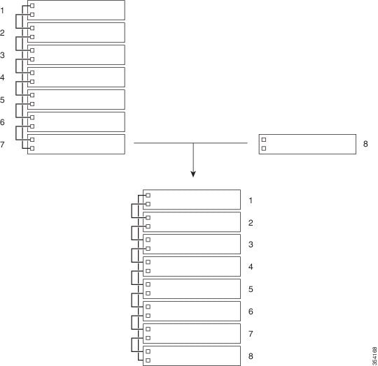
Up to eight members can be connected as a group through single IP-managed ports. A group always has one active switch, with other devices acting as member switches.
You can have a group with only one active switch and one member switch too. The maximum number in the group is eight. You can connect standalone devices to an existing group to increase the membership.
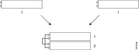
We recommend that you use half-ring topology for two-member stacks. Full-ring topology is generally used for three or more member stacks to provide redundancy when an intermediate switch goes down and loses connection with other members of the single IP managed group.
Persistent MAC Address
A group's MAC address is determined by the MAC address of the active switch. When an active switch is removed from the group, and a new active switch takes over, the default behavior is for the MAC address of the new active switch to immediately become the new MAC router address. However, you can enable the Persistent MAC Address feature to allow a time delay before the group MAC address changes.
During this time period, if the previous active switch rejoins the group, the group continues to use the previous active switch's MAC address as the group MAC address, even if the device is now a member switch, and not an active switch. If the previous active switch does not rejoin the group during this period, the group takes the MAC address of the new active switch as the group MAC address. You can also configure MAC persistency, so that the group never switches to the MAC address of the new active switch. If the entire group reloads, it uses the MAC address of the active switch as the group MAC address.
 Caution |
When you configure the stack-mac persistent timer command to configure the Persistent MAC Address feature, a warning message appears on the console. Use this feature with caution. Using the old device MAC address elsewhere in the same domain can result in lost traffic. |
The following guidelines are applicable to the stack-mac persistent timer command:
-
You can configure a time period from 0 to 60 minutes as the persistent timer.
-
If you enter the stack-mac persistent timer command with no value, the default delay is 4 minutes. We recommend that you always enter a value. If the command is entered without a value, the time delay appears in the running configuration file with an explicit timer value of 4 minutes.
-
If you enter 0 as the persistent timer, the group MAC address of the previous active switch is used until you configure the no stack-mac persistent timer command, which immediately changes the group MAC address to that of the current active switch. If you do not configure the no stack-mac persistent timer command, the group MAC address never changes.
-
If you enter a time delay of 1 to 60 minutes, the group MAC address of the previous active switch is used until the configured time period expires, or until you configure the no stack-mac persistent timer command.
Group Numbering Convention
The group member number (1 to 8) identifies each member in a group. This number also determines the interface-level configuration that a member uses. You can display the number by using the show switch command.
A new, out-of-the-box device (one that has not joined a group, or has not been manually assigned a number) ships with a default member number of 1. When it joins a group, its default number changes to the lowest available number in the corresponding group.
Members in the same group cannot have the same number. Every member, including a standalone device, retains its number until the number is manually changed, or the number is already being used by another member.
The following guidelines are applicable when configure a group-member number:
-
If you manually change the number by using the switch current-stack-member-number renumber new-stack-member-number command, the new number comes into effect after that member is reset (or after you configure the reload slot stack-member-number command), and only if that number is not already assigned to any member. You can also change the number by using the SWITCH_NUMBER environment variable.
If the same number is used by another member, the device selects the lowest available number in the group.
If you manually change the number of a member, and no interface-level configuration is associated with that new number, that member is reset to its default configuration.
You cannot use the switch current-stack-member-number renumber new-stack-member-number command on a provisioned device. The command is rejected.
-
If you move a member to a different group, the member retains its number only if that number is not used by another member. If it is used, the device selects the lowest available number in the group.
-
If you merge groups, the device that joins the group of a new active switch selects the lowest available number in the group.
Note |
If you connect a single IP-managed port to a normal network port on the other end, transmission and reception of packets are disabled within 30 seconds if no Stacking Discovery Protocol (SDP) packets are received from the other end. The port will not go down, but transmission and reception are disabled, and the following log message is displayed on the console. |
After a peer end network port is converted to a single IP-manged port, transmission and reception on this port is enabled.
Priority Values
A higher priority value for a member increases the probability of it being elected as the active switch and retaining its number. The priority values are from 1 to 15; 1 being the lowest and 15 the highest. The default priority value is 1. You can display the member priority value by using the show switch command.
To change the priority value for a member, use the switch stack-member-number priority new priority-value command.
The new priority value takes effect immediately, but does not affect the current active switch. The new priority value helps determine which member is elected as the new active switch when the current active switch or group is reset.
Election of Group Active Switch
A group's active switch is elected or reelected based on one of the following factors and in the order listed below:
-
The device that is currently the active switch.
-
The device with the highest member priority value.
Note
We recommend that you assign the highest priority value to the device that you prefer to be the active switch. This ensures that the device is reelected as active switch if a reelection occurs.
-
The device with the lowest MAC address.
Group Configuration Files
The saved and running configuration files for a group are available with the active switch. All the member switches periodically receive synchronized copies of the configuration files from the active switch. If the active switch becomes unavailable, any member switch that assumes the role of active switch will have the latest configuration files.
The configuration files record the following settings:
-
System-level (global) configuration settings such as IP, Simple Network Management Protocol (SNMP), Spanning Tree Protocol (STP), and VLAN, which apply to all member switches.
-
Interface-specific configuration settings of all member switches.
Note |
The interface-specific settings of the active switch are saved if the active switch is replaced without saving the running configuration. |
A new, out-of-box device that joins a group uses the system-level settings of that group. If a device is moved to a different group before it is powered on, that device loses its saved configuration file, and uses the system-level configuration of the new group. If the device is powered on as a standalone device before it joins the new group, the group reloads. When the group reloads, the new device may become the active switch, or retain its configuration, and overwrite the configuration files of the other member switches.
The interface-specific configuration of each member switch is associated with a member number. Member switches retain their number unless they are manually changed, or the number is used by another member in the same group. If a number changes, the new number comes into effect after the corresponding member is reset.
-
If an interface-specific configuration does not exist for a number, the member switch uses its default interface-specific configuration.
-
If an interface-specific configuration exists for a number, the member switch uses the interface-specific configuration associated with that number.
If you replace a failed member with an identical model, the replacement member automatically uses the same interface-specific configuration as the failed device. You do not have to reconfigure the interface settings. Note that the replacement device (referred to as the provisioned device) must have the same member number as the failed device.
Back up and restore the configuration the same way you would for a standalone device configuration.
Protocol Version
Each software image includes a group protocol version. The protocol version has a major version number and a minor version number, for example 1.4, where 1 is the major version number and 4 is the minor version number. Both version numbers determine the level of compatibility among the member switches. You can display the protocol version by using the show platform stack manager all command.
Devices with the same Cisco IOS software version have the same protocol version. Such devices are fully compatible, and all the features function properly across the group. A device with the same Cisco IOS software version as the active switch can immediately join the group.
If an incompatibility exists, the fully functional member switches generate a system message that describes the cause of the incompatibility on the specific member switches. The active switch sends the message to all the member switches.
Member Management
A group and the corresponding member interfaces are managed through the master. You can use the CLI, SNMP, and supported network management applications to manage the group. You cannot manage members on an individual basis. You can also use the GUI to manage members.
Configuration Scenarios
|
Scenario |
Result |
|
|---|---|---|
|
Active switch election specifically determined by the existing active switch. |
Connect two powered-on groups. |
Only one of the two active switches becomes the new active switch. |
|
Active switch election specifically determined by the member switch priority value. |
|
The member switch with the higher priority value is elected active switch. |
|
Active switch election specifically determined by the configuration file. |
Assuming that both member switches have the same priority value:
|
The member switch with the saved configuration file is elected the active switch. |
|
Active switch election specifically determined by the cryptographic software image. |
Assuming that all member switches have the same priority value:
|
The member switch with the cryptographic image is elected active switch. |
|
Active switch election specifically determined by the MAC address. |
Assuming that both member switches have the same priority value, configuration file, feature set and license level, restart both member switches at the same time. |
The member switch with the lower MAC address is elected active switch. |
|
Member-number conflict. |
Assuming that one member switch has a higher priority value than the other member switch:
|
The member switch with the higher priority value retains its member number. The other member switch has a new member number. |
|
New member switch added. |
|
The active switch is retained. The new device is added to the group. |
|
Active switch failure. |
Remove (or power off) the active switch. |
One of the remaining member switches becomes the new active switch. All the other member switches in the group remain as member switches and do not reboot. |
|
Add more than eight member switches. |
|
Two devices become active switches. One active switch has eight member switches. The other active switch remains as a standalone device. |
How to Configure Single IP Management
The following sections provide information about the various tasks to configure single IP management.
Configuring a Network Port as a Single IP-Managed Port
You can configure both the network ports as single IP-managed ports, or configure one port as a single IP-managed port and retain the other as a network port.
SUMMARY STEPS
- enable
- configure terminal
- switch switch-number hstack-port stack-port-number stack-port
- end
- copy running-config startup-config
- reload
- show switch hstack-ports
DETAILED STEPS
| Command or Action | Purpose | |
|---|---|---|
| Step 1 |
enable Example: |
Enables privileged EXEC mode.
|
| Step 2 |
configure terminal Example: |
Enters global configuration mode. |
| Step 3 |
switch switch-number hstack-port stack-port-number stack-port Example: |
Configures a network port into as a single IP-managed port. |
| Step 4 |
end Example: |
Exits global configuration mode and returns to privileged EXEC mode. |
| Step 5 |
copy running-config startup-config Example: |
Saves your entries in the configuration file. |
| Step 6 |
reload Example: |
Reloads the configuration. |
| Step 7 |
show switch hstack-ports Example: |
Displays the single IP-managed ports. |
What to do next
To convert a single IP-managed port into a network port, run the no switch switch-number hstack-port stack-port command:
Device(config)# no switch 1 hstack-port 1 GigabitEthernet 1/0/9
Device# copy running-config startup-config
Device# reload
Note |
When you configure the write erase and then the reload commands, the device in a group is not converted to standalone. Manual conversion is required. |
Enabling the Persistent MAC Address Feature
Follow these steps to enable persistent MAC address.
SUMMARY STEPS
- enable
- configure terminal
- stack-mac persistent timer [0 | time-value ]
- end
DETAILED STEPS
| Command or Action | Purpose | |||
|---|---|---|---|---|
| Step 1 |
enable Example: |
Enables privileged EXEC mode.
|
||
| Step 2 |
configure terminal Example: |
Enters global configuration mode. |
||
| Step 3 |
stack-mac persistent timer [0 | time-value ] Example: |
Enables a time delay after the active switch is changed, and before the group MAC address changes to that of the new active switch.
|
||
| Step 4 |
end Example: |
Exits global configuration mode and returns to privileged EXEC mode. |
Assigning a Group Member Number
This task is available only from the active switch.
SUMMARY STEPS
- enable
- configure terminal
- switch current-stack-member-number renumber new-stack-member-number
- end
- reload slot current-stack-member-number
- show switch
DETAILED STEPS
| Command or Action | Purpose | |
|---|---|---|
| Step 1 |
enable Example: |
Enables privileged EXEC mode.
|
| Step 2 |
configure terminal Example: |
Enters global configuration mode. |
| Step 3 |
switch current-stack-member-number renumber new-stack-member-number Example: |
Specifies the current number and the new number for the member. The range is from 1 to 8.
|
| Step 4 |
end Example: |
Exits global configuration mode and returns to privileged EXEC mode. |
| Step 5 |
reload slot current-stack-member-number Example: |
Reloads the member. |
| Step 6 |
show switch Example: |
Displays information about the member. |
Setting the Priority Value
This task is available only from the active switch.
SUMMARY STEPS
- enable
- configure terminal
- switch stack-member-number priority new-priority-number
- end
- show switch stack-member-number
DETAILED STEPS
| Command or Action | Purpose | |
|---|---|---|
| Step 1 |
enable Example: |
Enables privileged EXEC mode.
|
| Step 2 |
configure terminal Example: |
Enters global configuration mode. |
| Step 3 |
switch stack-member-number priority new-priority-number Example: |
Specifies the number and the new priority for the member switch. The priority value range is from 1 to 15.
|
| Step 4 |
end Example: |
Exits global configuration mode and returns to privileged EXEC mode. |
| Step 5 |
show switch stack-member-number Example: |
Verifies the priority value of the member switch. |
Provisioning a New Member
This task is available only from the active switch.
SUMMARY STEPS
- enable
- show switch
- configure terminal
- switch stack-member-number provision type
- end
DETAILED STEPS
| Command or Action | Purpose | |
|---|---|---|
| Step 1 |
enable Example: |
Enables privileged EXEC mode.
|
| Step 2 |
show switch Example: |
Displays summary information about the group. |
| Step 3 |
configure terminal Example: |
Enters global configuration mode. |
| Step 4 |
switch stack-member-number provision type Example: |
Specifies the member number for the preconfigured device. By default, no devices are provisioned.
|
| Step 5 |
end Example: |
Exits global configuration mode and returns to privileged EXEC mode. |
Removing Information About a Provisioned Device
This task is available only from the active switch.
SUMMARY STEPS
- enable
- configure terminal
- no switch stack-member-number provision
- end
DETAILED STEPS
| Command or Action | Purpose | |
|---|---|---|
| Step 1 |
enable Example: |
Enables privileged EXEC mode.
|
| Step 2 |
configure terminal Example: |
Enters global configuration mode. |
| Step 3 |
no switch stack-member-number provision Example: |
Removes the provisioning information for the specified member switch. |
| Step 4 |
end Example: |
Exits global configuration mode and returns to privileged EXEC mode. |
Example
This subsection provides details of a sample scenario. A provisioned device is being removed from a group having the following configuration:
-
This group has four members.
-
Member 1 is the active switch.
-
Member 3 is a provisioned device.
To avoid receiving an error message, do the following:
-
Remove the power from member 3.
-
Disconnect the cables between member 3 and the devices to which it is connected to.
-
Reconnect the cables between the remaining members.
-
Configure the no switch stack-member-number provision command.
Configuration Examples for Single IP Management
Example: Enabling the Persistent MAC Address Feature
The following example shows how to configure the persistent MAC address feature for a 7-minute time delay, and to verify the configuration:
Device(config)# stack-mac persistent timer 7

		WARNING: The stack continues to use the base MAC of the old Master
		WARNING: as the stack MAC after a master switchover until the MAC
		WARNING: persistency timer expires. During this time the Network
		WARNING: Administrators must make sure that the old stack-mac does
		WARNING: not appear elsewhere in this network domain. If it does,
		WARNING: user traffic may be blackholed.
		Device(config)# end
		Device# show switch

		Switch/Stack Mac Address : 0016.4727.a900
		Mac persistency wait time: 7 mins
		                                           H/W   Current
		Switch#  Role   Mac Address     Priority Version  State
		----------------------------------------------------------
		*1       Master 0016.4727.a900     1      P2B     Ready
Example: Provisioning a New Member
The following example shows how to provision a device with a member number of 2. The show running-config command output shows the interfaces associated with the provisioned device:
Device(config)# switch 2 provision switch_PID
Device(config)# end
Device# show running-config | include switch 2

switch 2 provision switch_PID
Example: Configuring a Network Port into a Single IP-Managed Port
The following example shows how to convert a network port on a 1-G device:
Device> enable
Device# configure terminal
Device(config)# switch 1 hstack-port 1 GigabitEthernet 1/0/9
Do you want to continue?[confirm]
New port setting will be effective after next reload

Device(config)# switch 1 hstack-port 2 GigabitEthernet 1/0/10
Do you want to continue?[confirm]
New port setting will be effective after next reload
The following sample output from the show switch hstack-ports command shows the status of ports before reloading:
Device# show switch hstack-ports

 Horizontal stack port status :
 Gi Ports   Stack Port   Operational Status   Next Reload Status   Media Type
 --------- ------------ -------------------- ------------------- --------------
 Gi1/0/9      1           N/W Port             Stack Port            Fiber
 Gi1/0/10     2           N/W Port             Stack Port            Fiber
The following sample output from the show switch hstack-ports command shows the status of the ports after a reload:
Device# show switch hstack-ports

 Horizontal stack port status :
 Gi Ports   Stack Port   Operational Status   Next Reload Status   Media Type
 --------- ------------ -------------------- ------------------- --------------
 Gi1/0/9      1           Stack Port             Stack Port            Fiber
 Gi1/0/10     2          Stack Port             Stack Port            Fiber
The following example shows how to convert a network port to a single IP-managed port on a 10-G device:
Device> enable
Device#configure terminal
Device(config)# switch 1 hstack-port 1 TenGigabitEthernet 1/0/1
Do you want to continue?[confirm]
New port setting will be effective after next reload


Device(config)# switch 1 hstack-port 2 TenGigabitEthernet 1/0/2
Do you want to continue?[confirm]
New port setting will be effective after next reload
The following sample output from the show switch hstack-ports command shows the status of ports before a reload:
Device# show switch hstack-ports

 Horizontal stack port status :
 Te Ports   Stack Port   Operational Status   Next Reload Status   Media Type
 --------- ------------ -------------------- ------------------- --------------
 Te1/0/1      1           N/W Port           Stack Port           Fiber
 Te1/0/2      2           N/W Port           Stack Port           Fiber
 Te1/0/3      NA          N/W Port           N/W Port             Fiber
 Te1/0/4      NA          N/W Port           N/W Port             Fiber
The following sample output from the show switch hstack-ports command shows the status of ports after a reload:
Device# show switch hstack-ports

 Horizontal stack port status :
 Te Ports   Stack Port   Operational Status   Next Reload Status   Media Type
 --------- ------------ -------------------- ------------------- --------------
 Te1/0/1      1           Stack Port          Stack Port          Fiber
 Te1/0/2      2           Stack Port          Stack Port          Fiber
 Te1/0/3      NA          N/W Port            N/W Port            Fiber
 Te1/0/4      NA          N/W Port            N/W Port            Fiber
The following example shows how to convert a single IP-managed port back to a network port.
Device> enable
Device#configure terminal
Device(config)#no switch 1 hstack-port 1
Do you want to continue?[confirm]
New port setting will be effective after next reload
The following sample output from the show switch hstack-ports command shows the status of ports before a reload on a 10-G device:
Device# show switch hstack-ports

 Horizontal stack port status :
 Te Ports   Stack Port   Operational Status   Next Reload Status   Media Type
 --------- ------------ -------------------- ------------------- --------------
 Te1/0/1      1           Stack Port          N/W Port            Fiber
 Te1/0/2      2           Stack Port          Stack Port          Fiber
 Te1/0/3      NA           N/W Port           N/W Port            Fiber
 Te1/0/4      NA           N/W Port           N/W Port            Fiber
The following sample output from the show switch hstack-ports command shows the status of a port on a 10-G device:
Device# show switch hstack-ports

 Horizontal stack port status :
 Te Ports   Stack Port   Operational Status   Next Reload Status   Media Type
 --------- ------------ -------------------- ------------------- --------------
 Te1/0/1      1           N/W Port            N/W Port            Fiber
 Te1/0/2      2           Stack Port          Stack Port          Fiber
 Te1/0/3      NA          N/W Port            N/W Port            Fiber
 Te1/0/4      NA          N/W Port            N/W Port            Fiber
The following sample output from the show switch hstack-ports command shows the status of single IP-managed ports for a 1-G group:
Device# show switch hstack-ports

 Horizontal stack port status :
Gi Ports   Stack Port   Operational Status   Next Reload Status   Media Type
--------- ------------ -------------------- ------------------- -------------
Gi1/0/25      NA           N/W Port           N/W Port            Fiber
Gi1/0/26      1            Stack Port         Stack Port          Fiber
Gi1/0/27      2            Stack Port         Stack Port          Fiber
Gi1/0/28      NA           N/W Port           N/W Port            Fiber
Gi2/0/49      1            Stack Port         Stack Port          Fiber
Gi2/0/50      NA           N/W Port           N/W Port            Fiber
Gi2/0/51      2            Stack Port         Stack Port          Fiber
Gi2/0/52      NA           N/W Port           N/W Port            Fiber
Gi3/0/49      NA           N/W Port           N/W Port            Fiber
Gi3/0/50      1            Stack Port         Stack Port          Fiber
Gi3/0/51      NA           N/W Port           N/W Port            Fiber
Gi3/0/52      2            Stack Port         Stack Port          Fiber
Gi4/0/9       1            Stack Port         Stack Port          Fiber
Gi4/0/10      2            Stack Port         Stack Port          Fiber
Gi5/0/9       1            Stack Port         Stack Port          Fiber
Gi5/0/10      2            Stack Port         Stack Port          Fiber
Gi6/0/17      1            Stack Port         Stack Port          Fiber
Gi6/0/18      2            Stack Port         Stack Port          Fiber
Gi7/0/17      1            Stack Port         Stack Port          Fiber
Gi7/0/18      2            Stack Port         Stack Port          Fiber
Gi8/0/9       1            Stack Port         Stack Port          Fiber
Gi8/0/10      2            Stack Port         Stack Port          Fiber
The following sample output from the show switch hstack-ports command shows the status of single IP-managed ports for a 10-G group:
Device# show switch hstack-ports

Horizontal stack port status :
Te Ports   Stack Port   Operational Status   Next Reload Status   Media Type
--------- ------------ -------------------- ------------------- -------------
Te1/0/1       1            Stack Port         Stack Port          Fiber
Te1/0/2       NA           N/W Port           N/W Port            Fiber
Te1/0/3       NA           N/W Port           N/W Port            Fiber
Te1/0/4       2            Stack Port         Stack Port          Fiber
Te2/0/1       1            Stack Port         Stack Port          Fiber
Te2/0/2       2            Stack Port         Stack Port          Fiber
Te2/0/3       NA           N/W Port           N/W Port            Fiber
Te2/0/4       NA           N/W Port           N/W Port            Fiber
Te3/0/1       NA           N/W Port           N/W Port            Fiber
Te3/0/2       1            Stack Port         Stack Port          Fiber
Te3/0/3       NA           N/W Port           N/W Port            Fiber
Te3/0/4       2            Stack Port         Stack Port          Fiber
Te4/0/1       NA           N/W Port           N/W Port            Fiber
Te4/0/2       1            Stack Port         Stack Port          Fiber
Te4/0/3       NA           N/W Port           N/W Port            Fiber
Te4/0/4       2            Stack Port         Stack Port          Fiber
Te6/0/1       NA           N/W Port           N/W Port            Fiber
Te6/0/2       1            Stack Port         Stack Port          Fiber
Te6/0/3       2            Stack Port         Stack Port          Fiber
Te6/0/4       NA           N/W Port           N/W Port            Fiber
Te7/0/1       1            Stack Port         Stack Port          Fiber
Te7/0/2       NA           N/W Port           N/W Port            Fiber
Te7/0/3       2            Stack Port         Stack Port          Fiber
Te7/0/4       NA           N/W Port           N/W Port            Fiber
Additional References
Related Documents
| Related Topic | Document Title |
|---|---|
|
Commands |
Command Reference, Cisco IOS Release 15.2(7)E1 (Catalyst 1000 Switches) |
Technical Assistance
| Description | Link |
|---|---|
|
The Cisco Support website provides extensive online resources, including documentation and tools for troubleshooting and resolving technical issues with Cisco products and technologies. To receive security and technical information about your products, you can subscribe to various services, such as the Product Alert Tool (accessed from Field Notices), the Cisco Technical Services Newsletter, and Really Simple Syndication (RSS) Feeds. Access to most tools on the Cisco Support website requires a Cisco.com user ID and password. |
Feature Information for Single IP Management
The following table provides release information about the feature or features described in this module. This table lists only the software release that introduced support for a given feature in a given software release train. Unless noted otherwise, subsequent releases of that software release train also support that feature.
Use Cisco Feature Navigator to find information about platform support and Cisco software image support. To access Cisco Feature Navigator, go to www.cisco.com/go/cfn. An account on Cisco.com is not required.|
Feature Name |
Releases |
Feature Information |
|---|---|---|
|
Single IP Management |
Cisco IOS Release 15.2(7)E1 |
The Cisco Catalyst 1000 Series Switches that support 1-G and 10-G SFP and SFP+ uplink ports can be part of single IP management. You can use SFP and SFP+ ports with optical cables to connect boxes placed at different locations to form a group, where the compact boxes are placed in different floors or buildings. |
 Feedback