Fabrics
This section contains the following topics:
VXLAN BGP EVPN Fabrics Provisioning
In DCNM 11.0(1), fabric creation is enhanced to provision VXLAN BGP EVPN underlay network parameters to the fabric switches. The concept of Multi-Site Domain (MSD) fabrics was introduced.
In the DCNM 11.1(1) and 11.2(1) releases, further enhancements are made. For the LAN Fabric deployment type, fabric template support is introduced for Cisco Nexus 3000 Series switches, in addition to the existing support for Cisco Nexus 9000 Series switches.
Support of simplified CLIs for VXLAN EVPN fabrics is not supported in either greenfield or brownfield deployments.
The DCNM GUI functions for creating, deploying, and migrating VXLAN fabrics are as follows
Control > Fabric Builder menu option (under the Fabrics sub menu).
Create, edit, and delete a fabric:
-
Create new VXLAN, MSD and external VXLAN fabrics.
-
View the VXLAN and MSD fabric topologies, including connections between fabrics.
-
Update fabric settings.
-
Save and deploy updated changes.
-
Delete a fabric (if devices are removed).
Fabric Membership changes
-
Transition existing VXLAN fabric management to DCNM (through the Preserve Config = Yes option).
-
Deploy new fabrics or add new devices to an existing fabric (through the bootstrap or Preserve Config = No options).
-
Move fabrics into or out of an MSD.
Device discovery and provisioning start-up configurations on new switches:
-
Add switch instances to the fabric.
-
Provision start-up configurations and an IP address to a new switch through POAP configuration.
-
Update switch policies, save and deploy updated changes.
-
Create intra-fabric and inter-fabric links (also called Inter-Fabric Connections [IFCs]).
Transitioning VXLAN fabric management to DCNM
In DCNM 11.1(1) release, transitioning existing VXLAN fabric management to DCNM is introduced.
Control > Interfaces menu option (under the Fabrics sub menu).
Underlay provisioning:
-
Create, deploy, view, edit and delete a port-channel, vPC switch pair, straight through FEX, AA FEX, loopback, and subinterface.
-
Create breakout and unbreakout ports.
-
Shut down and bring up interfaces.
-
Rediscover ports and view interface configuration history.
-
Designate a switch interface as a routed port, trunk port, OSPF interface, and so on.

Note
vPC support is added for BGWs in the DCNM 11.1(1) release.
Control > Networks and Control > VRFs menu options (under the Fabrics sub menu).
Overlay network provisioning.
-
Create new overlay networks and VRFs (from the range specified in fabric creation).
-
Provision the overlay networks and VRFs on the switches of the fabric.
-
Undeploy the networks and VRFs from the switches.
-
Remove the provisioning from the fabric in DCNM.
This chapter mostly covers standalone fabric-related configurations. MSD fabric documentation is available in a separate chapter. The deployment of networks and VRFs is covered under the Networks and VRFs Creation and Deployment topic. Step by step configuration:
Guidelines for VXLAN BGP EVPN Fabrics Provisioning
-
When an invalid command is deployed by DCNM to a device, for example, a command with an invalid key chain due to an invalid entry in the fabric settings, an error is generated displaying this issue. This error is not cleared after correcting the invalid fabric entry. You need to manually cleanup or delete the invalid commands to clear the error.
Note that the fabric errors related to the command execution are automatically cleared only when the same failed command succeeds in the subsequent deployment.
-
When LAN credentials are not set for a device, DCNM moves this device to the maintenance mode. However, DCNM also displays a pop-up message saying that this device is not set to the maintenance mode. Ignore this message because the switch will be in the maintenance mode as seen in the Topology view.
-
Ingress replication is not supported on Cisco Nexus C36180YC-R Switch.
-
Persistent configuration diff is seen for the command line: system nve infra-vlan int force . The persistent diff occurs if you have deployed this command via the freeform configuration to the switch. Although the switch requires the force keyword during deployment, the running configuration that is obtained from the switch in DCNM does not display the force keyword. Therefore, the system nve infra-vlan int force command always shows up as a diff.
The intent in DCNM contains the line:
system nve infra-vlan int forceThe running config contains the line:
system nve infra-vlan intNote that the switch does not display the force keyword as being applied. However, the force keyword is required by the switch to be deployed.
As a workaround to fix the persistent diff, edit the freeform config to remove the force keyword after the first deployment such that it is system nve infra-vlan int force .
The force keyword is required for the initial deploy and must be removed after a successful deploy. You can confirm the diff by using the Side-by-side Comparison tab in the Config Preview window.
The persistent diff is also seen after a write erase and reload of a switch. Update the intent on DCNM to include the force keyword, and then you need to remove the force keyword after the first deployment.
-
The Save & Deploy button triggers the intent regeneration for the entire fabric as well as a configuration compliance check for all the switches within the fabric. This button is required but not limited to the following cases:
-
A switch or a link is added, or any change in the topology
-
A change in the fabric settings that must be shared across the fabric
-
A switch is removed or deleted
-
A new vPC pairing or unpairing is done
-
A change in the role for a device
When you click Save & Deploy, the changes in the fabric are evaluated, and the configuration for the entire fabric is generated. You can preview the generated configuration, and then deploy it at a fabric level. Therefore, Save & Deploy can take more time depending on the size of the fabric.
When you right-click on a switch icon, you can use the Deploy Config option to deploy per switch configurations. This option is a local operation for a switch, that is, the expected configuration or intent for a switch is evaluated against it’s current running configuration, and a config compliance check is performed for the switch to get the IN-SYNC or OUT-OF-SYNC status. If the switch is out of sync, the user is provided with a preview of all the configurations running in that particular switch that vary from the intent defined by the user for that respective switch.
Note that the fabric builder does not re-evaluate the topology or generate any dependent configuration for that switch or any other devices that are part of the fabric.
-
-
When the switch contains the hardware access-list tcam region arp-ether 256 command, which is deprecated without the double-wide keyword, the below warning is displayed:
WARNING: Configuring the arp-ether region without "double-wide" is deprecated and can result in silent non-vxlan packet drops. Use the "double-wide" keyword when carving TCAM space for the arp-ether region.
Since the original hardware access-list tcam region arp-ether 256 command does not match the policies in DCNM, this config is captured in the switch_freeform policy. After the hardware access-list tcam region arp-ether 256 double-wide command is pushed to the switch, the original tcam command that does not contain the double-wide keyword is removed.
You must manually remove the hardware access-list tcam region arp-ether 256 command from the switch_freeform policy. Otherwise, config compliance shows a persistent diff.
Here is an example of the hardware access-list command on the switch:
switch(config)# show run | inc arp-ether
switch(config)# hardware access-list tcam region arp-ether 256
Warning: Please save config and reload the system for the configuration to take effect
switch(config)# show run | inc arp-ether
hardware access-list tcam region arp-ether 256
switch(config)#
switch(config)# hardware access-list tcam region arp-ether 256 double-wide
Warning: Please save config and reload the system for the configuration to take effect
switch(config)# show run | inc arp-ether
hardware access-list tcam region arp-ether 256 double-wide
You can see that the original tcam command is overwritten.
Creating a New VXLAN BGP EVPN Fabric
This procedure shows how to create a new VXLAN BGP EVPN fabric.
Note that this procedure contains descriptions for the IPv4 underlay. For information about IPv6 underlay, see IPv6 Underlay Support for Easy Fabric.
-
Choose Control > Fabric Builder.
The Fabric Builder screen appears. When you log in for the first time, the Fabrics section has no entries. After you create a fabric, it is displayed on the Fabric Builder screen, wherein a rectangular box represents each fabric.
A standalone or member fabric contains Switch_Fabric (in the Type field), the AS number (in the ASN field), and mode of replication (in the Replication Mode field).
-
Click Create Fabric. The Add Fabric screen appears.
The fields are explained:
Fabric Name - Enter the name of the fabric.
Fabric Template - From the drop-down menu, choose the Easy_Fabric_11_1 fabric template. The fabric settings for creating a standalone fabric comes up.
The tabs and their fields in the screen are explained in the subsequent points. The overlay and underlay network parameters are included in these tabs.
Note
If you are creating a standalone fabric as a potential member fabric of an MSD fabric (used for provisioning overlay networks for fabrics that are connected through EVPN Multi-Site technology), then browse through the Multi-Site Domain for VXLAN BGP EVPN Fabrics topic before member fabric creation.
-
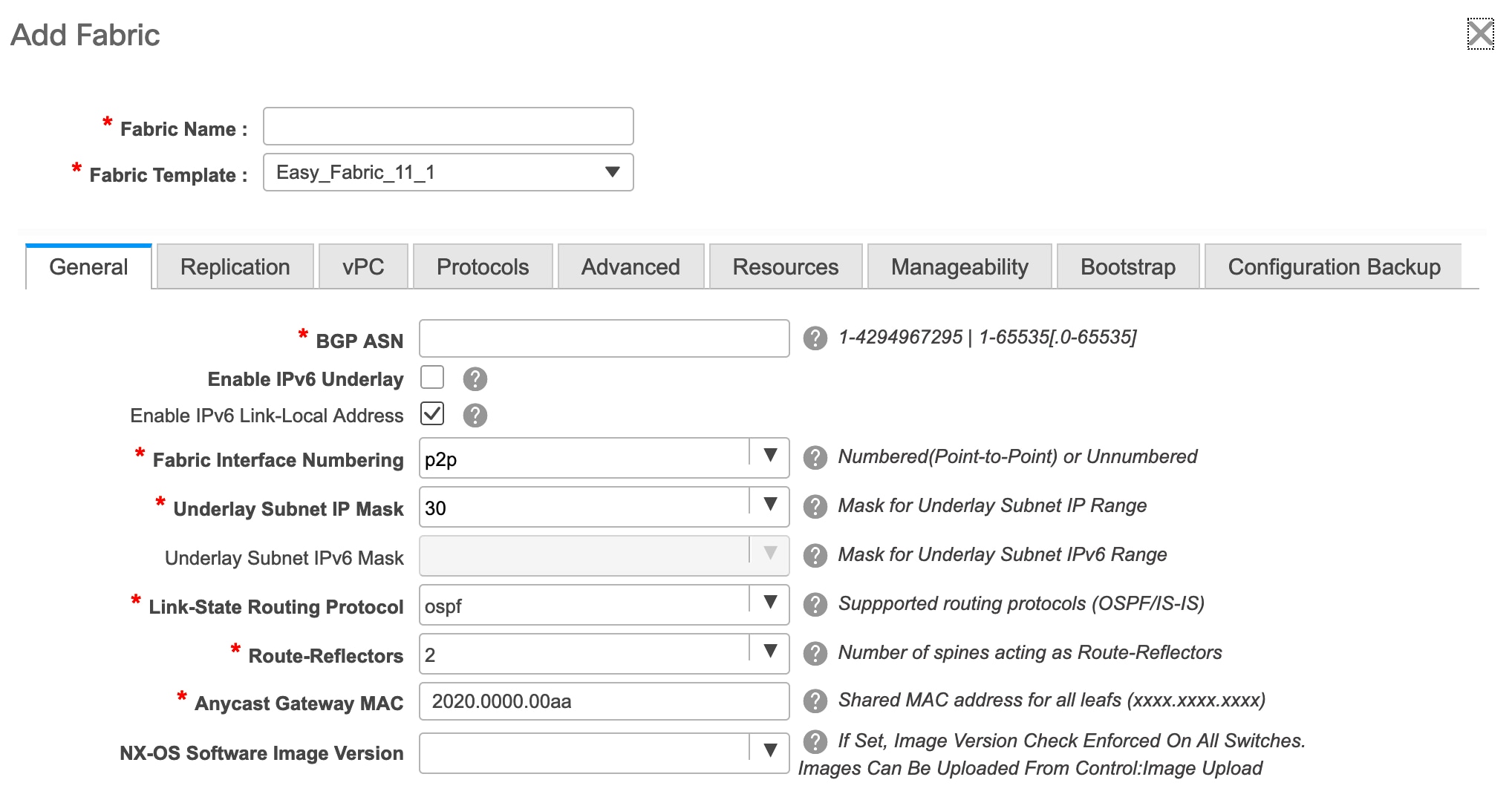
The General tab is displayed by default. The fields in this tab are:
BGP ASN: Enter the BGP AS number the fabric is associated with.
Enable IPv6 Underlay: Enable the IPv6 underlay feature. For information, see IPv6 Underlay Support for Easy Fabric.
Enable IPv6 Link-Local Address: Enables the IPv6 Link-Local address.
Fabric Interface Numbering : Specifies whether you want to use point-to-point (p2p) or unnumbered networks. For information about how to change this field value for an existing fabric, see Changing Fabric Interface Numbering.
Underlay Subnet IP Mask - Specifies the subnet mask for the fabric interface IP addresses.
Link-State Routing Protocol : The IGP used in the fabric, OSPF, or IS-IS.
Route-Reflectors – The number of spine switches that are used as route reflectors for transporting BGP traffic. Choose 2 or 4 from the drop down box. The default value is 2.
To deploy spine devices as RRs, DCNM sorts the spine devices based on their serial numbers, and designates two or four spine devices as RRs. If you add more spine devices, existing RR configuration will not change.
Increasing the count - You can increase the route reflectors from two to four at any point in time. Configurations are automatically generated on the other 2 spine devices designated as RRs.
Decreasing the count
When you reduce four route reflectors to two, you must remove the unneeded route reflector devices from the fabric. Follow these steps to reduce the count from 4 to 2.
-
Change the value in the drop-down box to 2.
-
Identify the spine switches designated as route reflectors.
An instance of the rr_state policy is applied on the spine switch if it is a route reflector. To find out if the policy is applied on the switch, right-click the switch, and choose View/edit policies. In the View/Edit Policies screen, search rr_state in the Template field. It is displayed on the screen.
-
Delete the unneeded spine devices from the fabric (right-click the spine switch icon and choose Discovery > Remove from fabric).
If you delete existing RR devices, the next available spine switch is selected as the replacement RR.
-
Click Save and Deploy at the top right part of the fabric topology screen.
Anycast Gateway MAC : Specifies the anycast gateway MAC address.
NX-OS Software Image Version : Select an image from the list.
If you upload Cisco NX-OS software images through the image upload option, the uploaded images are listed in this field. If you select an image, the system checks if the switch has the selected version. If not, an error message is displayed. You can resolve the error by clicking on Resolve. The image management screen comes up and you can proceed with the ISSU option. Alternatively, you can delete the release number and save it later.
If you specify an image in this field, all switches in the fabric should run that image. If some devices do not run the image, a warning is prompted to perform an In-Service Software Upgrade (ISSU) to the specified image. Till all devices run the specified image, the deployment process will be incomplete.
If you want to deploy more than one type of software image on the fabric switches, don’t specify any image. If an image is specified, delete it
-
-
Click the Replication tab. Most of the fields are auto generated. You can update the fields if needed.
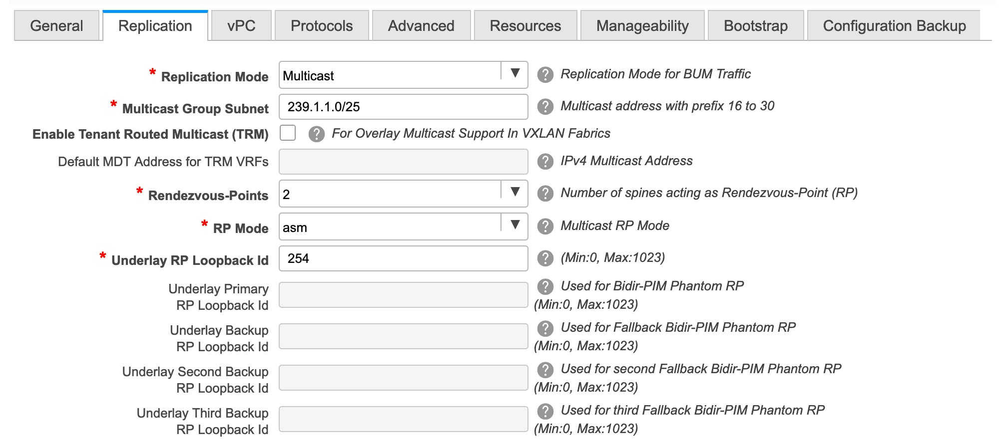
Replication Mode : The mode of replication that is used in the fabric, Ingress Replication, or Multicast.
When you choose Ingress replication, the multicast replication fields get disabled.
You can change the fabric setting from one mode to the other, if no overlay profile exists for the fabric.
Multicast Group Subnet : IP address prefix used for multicast communication. An unique IP address is allocated from this group for each overlay network.
In the DCNM 11.0(1) release, the replication mode change is not allowed if a policy template instance is created for the current mode. For example, if a multicast related policy is created and deployed, you cannot change the mode to Ingress.
Enable Tenant Routed Multicast (TRM) – Select the checkbox to enable Tenant Routed Multicast (TRM) as the fabric overlay multicast protocol.
Default MDT Address for TRM VRFs: The multicast address for Tenant Routed Multicast traffic is populated. By default, this address is from the IP prefix specified in the Multicast Group Subnet field. When you update either field, ensure that the TRM address is chosen from the IP prefix specified in Multicast Group Subnet.
Rendezvous-Points - Enter the number of spine switches acting as rendezvous points.
RP mode – Choose from the two supported multicast modes of replication, ASM (for Any-Source Multicast [ASM]) or BiDir (for Bidirectional PIM [BIDIR-PIM]).
When you choose ASM, the BiDir related fields are not enabled. When you choose BiDir, the BiDir related fields are enabled.
Note
BIDIR-PIM is supported on Cisco's Cloud Scale Family platforms 9300-EX and 9300-FX/FX2, and software release 9.2(1) onwards.
When you create a new VRF for the fabric overlay, this address is populated in the Underlay Multicast Address field, in the Advanced tab.
Underlay RP Loopback ID – The loopback ID used for the rendezvous point (RP), for multicast protocol peering purposes in the fabric underlay.
The next two fields are enabled if you choose BIDIR-PIM as the multicast mode of replication.
Underlay Primary RP Loopback ID – The primary loopback ID used for the phantom RP, for multicast protocol peering purposes in the fabric underlay.
Underlay Backup RP Loopback ID – The secondary loopback ID used for the phantom RP, for multicast protocol peering purposes in the fabric underlay.
Underlay Second Backup RP Loopback Id and Underlay Third Backup RP Loopback Id: Used for the second and third fallback Bidir-PIM Phantom RP.
-
Click the vPC tab. Most of the fields are auto generated. You can update the fields if needed.
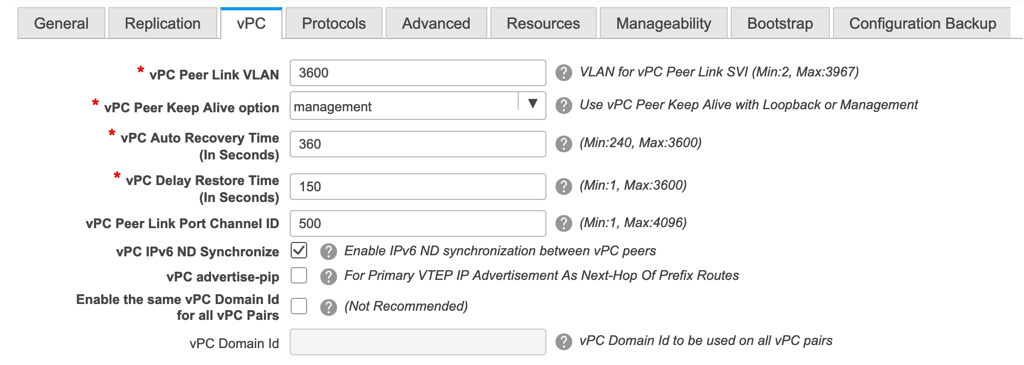
vPC Peer Link VLAN – VLAN used for the vPC peer link SVI.
vPC Peer Keep Alive option – Choose the management or loopback option. If you want to use IP addresses assigned to the management port and the management VRF, choose management. If you use IP addresses assigned to loopback interfaces (and a non-management VRF), choose loopback.
If you use IPv6 addresses, you must use loopback IDs.
vPC Auto Recovery Time - Specifies the vPC auto recovery time-out period in seconds.
vPC Delay Restore Time - Specifies the vPC delay restore period in seconds.
vPC Peer Link Port Channel ID - Specifies the Port Channel ID for a vPC Peer Link. By default, the value in this field is 500.
vPC IPv6 ND Synchronize – Enables IPv6 Neighbor Discovery synchronization between vPC switches. The check box is enabled by default. Clear the check box to disable the function.
vPC advertise-pip - Select the check box to enable the Advertise PIP feature.
Enable the same vPC Domain Id for all vPC Pairs: Enable the same vPC Domain ID for all vPC pairs. When you select this field, the vPC Domain Id field is editable.
vPC Domain Id - Specifies the vPC domain ID to be used on all vPC pairs.
-
Click the Protocols tab. Most of the fields are auto generated. You can update the fields if needed.
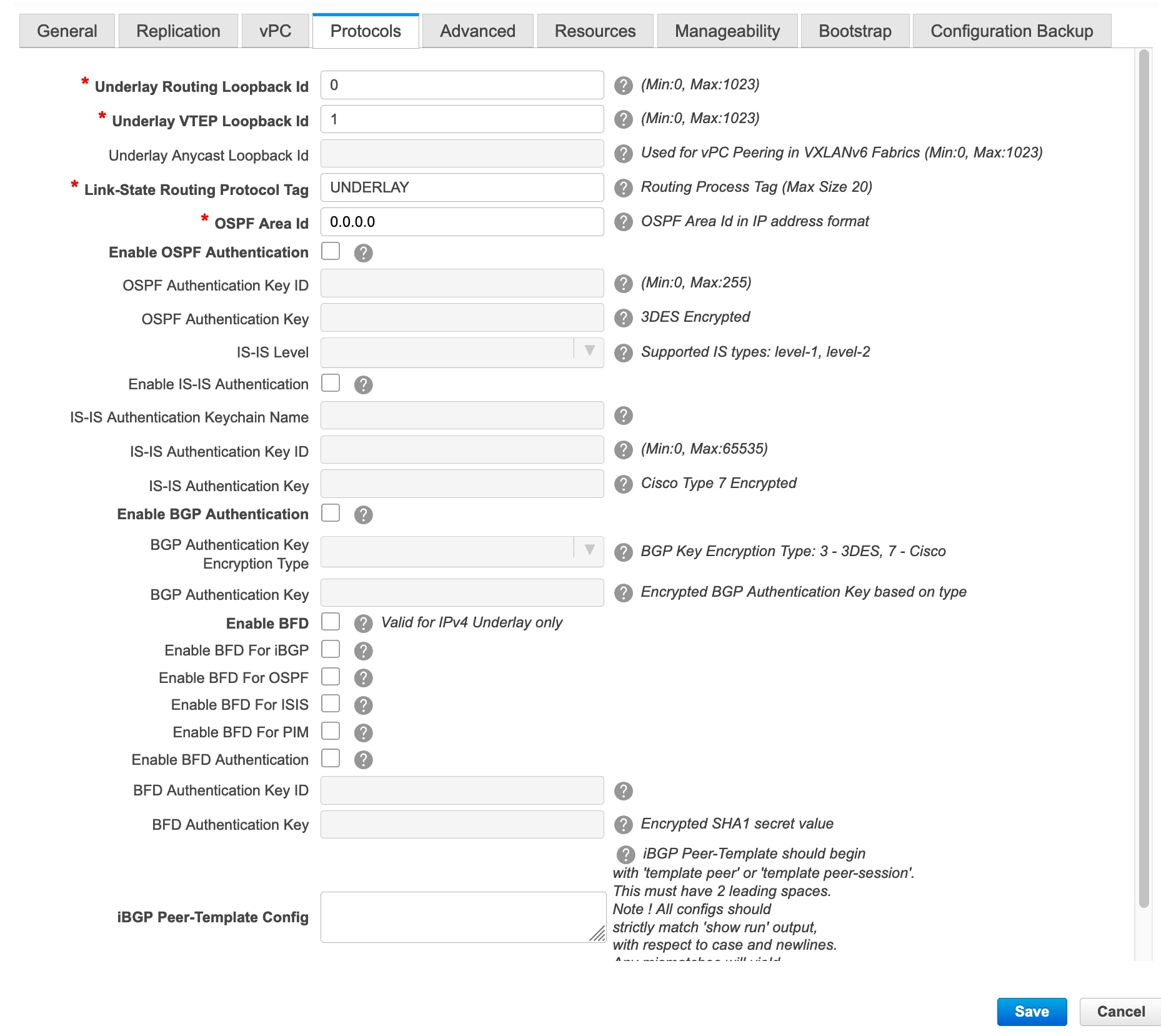
Underlay Routing Loopback Id - The loopback interface ID is populated as 0 since loopback0 is usually used for fabric underlay IGP peering purposes.
Underlay VTEP Loopback Id - The loopback interface ID is populated as 1 since loopback1 is usually used for the VTEP peering purposes.
Link-State Routing Protocol Tag - The tag defining the type of network.
OSPF Area ID – The OSPF area ID, if OSPF is used as the IGP within the fabric.
Note
The OSPF or IS-IS authentication fields are enabled based on your selection in the Link-State Routing Protocol field in the General tab.
Enable OSPF Authentication – Select the check box to enable OSPF authentication. Deselect the check box to disable it. If you enable this field, the OSPF Authentication Key ID and OSPF Authentication Key fields get enabled.
OSPF Authentication Key ID - The Key ID is populated.
OSPF Authentication Key - The OSPF authentication key must be the 3DES key from the switch.
Note
Plain text passwords are not supported. Login to the switch, retrieve the encrypted key and enter it in this field. Refer the Retrieving the Authentication Key section for details.
IS-IS Level - Select the IS-IS level from this drop-down list.
Enable IS-IS Authentication - Select the check box to enable IS-IS authentication. Deselect the check box to disable it. If you enable this field, the IS-IS authentication fields are enabled.
IS-IS Authentication Keychain Name - Enter the Keychain name, such as CiscoisisAuth.
IS-IS Authentication Key ID - The Key ID is populated.
IS-IS Authentication Key - Enter the Cisco Type 7 encrypted key.
Note
Plain text passwords are not supported. Login to the switch, retrieve the encrypted key and enter it in this field. Refer the Retrieving the Authentication Key section for details.
Enable BGP Authentication - Select the check box to enable BGP authentication. Deselect the check box to disable it. If you enable this field, the BGP Authentication Key Encryption Type and BGP Authentication Key fields are enabled.
Note
If you enable BGP authentication using this field, leave the iBGP Peer-Template Config field blank to avoid duplicate configuration.
BGP Authentication Key Encryption Type – Choose the 3 for 3DES encryption type, or 7 for Cisco encryption type.
BGP Authentication Key - Enter the encrypted key based on the encryption type.
Note
Plain text passwords are not supported. Login to the switch, retrieve the encrypted key and enter it in the BGP Authentication Key field. Refer the Retrieving the Authentication Key section for details.
Enable BFD: Select the check box to enable feature bfd on all switches in the fabric. This feature is valid only on IPv4 underlay and the scope is within a fabric.
From Cisco DCNM Release 11.3(1), BFD within a fabric is supported natively. The BFD feature is disabled by default in the Fabric Settings. If enabled, BFD is enabled for the underlay protocols with the default settings. Any custom required BFD configurations must be deployed via the per switch freeform or per interface freeform policies.
The following config is pushed after you select the Enable BFD check box:
feature bfdFor information about BFD feature compatibility, refer your respective platform documentation and for information about the supported software images, see Compatibility Matrix for Cisco DCNM.
Enable BFD for iBGP: Select the check box to enable BFD for the iBGP neighbor. This option is disabled by default.
Enable BFD for OSPF: Select the check box to enable BFD for the OSPF underlay instance. This option is disabled by default, and it is grayed out if the link state protocol is ISIS.
Enable BFD for ISIS: Select the check box to enable BFD for the ISIS underlay instance. This option is disabled by default, and it is grayed out if the link state protocol is OSPF.
Enable BFD for PIM: Select the check box to enable BFD for PIM. This option is disabled by default, and it is be grayed out if the replication mode is Ingress.
Here are the examples of the BFD global policies:
router ospf <ospf tag>
   bfd

router isis <isis tag>
  address-family ipv4 unicast
    bfd

ip pim bfd

router bgp <bgp asn>
  neighbor <neighbor ip>
    bfd
Enable BFD Authentication: Select the check box to enable BFD authentication. If you enable this field, the BFD Authentication Key ID and BFD Authentication Key fields are editable.
Note
-
BFD Authentication is not supported when the Fabric Interface Numbering field under the General tab is set to unnumbered. The BFD authentication fields will be grayed out automatically.
-
After you upgrade from DCNM Release 11.2(1) with BFD enabled to DCNM Release 11.3(1), the following configs are pushed to the switch:
no ip redirects
no ipv6 redirects
BFD Authentication Key ID: Specifies the BFD authentication key ID for the interface authentication. The default value is 100.
BFD Authentication Key: Specifies the BFD authentication key.
For information about how to retrieve the BFD authentication parameters, see Retrieving the Encrypted BFD Authentication Key.
iBGP Peer-Template Config – Add iBGP peer template configurations on the leaf switches to establish an iBGP session between the leaf switch and route reflector.
If you use BGP templates, add the authentication configuration within the template and clear the Enable BGP Authentication check box to avoid duplicate configuration.
In the sample configuration, the 3DES password is displayed after password 3.
router bgp 65000 password 3 sd8478fswerdfw3434fsw4f4w34sdsd8478fswerdfw3434fsw4f4w -
-
Click the Advanced tab. Most of the fields are auto generated. You can update the fields if needed.
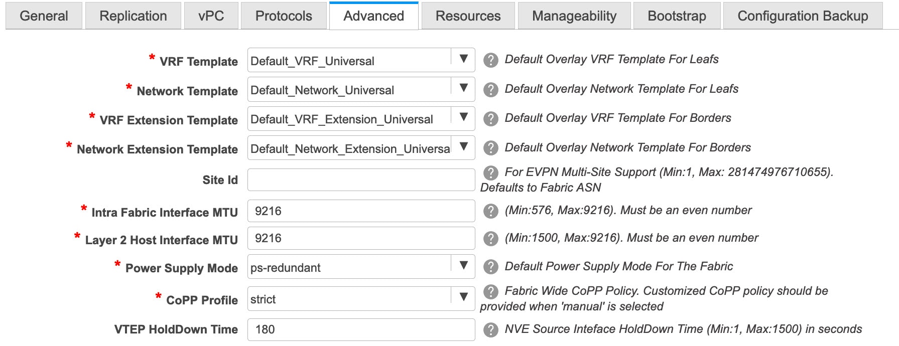
VRF Template and VRF Extension Template: Specifies the VRF template for creating VRFs, and the VRF extension template for enabling VRF extension to other fabrics.
Network Template and Network Extension Template: Specifies the network template for creating networks, and the network extension template for extending networks to other fabrics.
Site ID - The ID for this fabric if you are moving this fabric within an MSD. The site ID is mandatory for a member fabric to be a part of an MSD. Each member fabric of an MSD has a unique site ID for identification.
Intra Fabric Interface MTU - Specifies the MTU for the intra fabric interface. This value should be an even number.
Layer 2 Host Interface MTU - Specifies the MTU for the layer 2 host interface. This value should be an even number.
Power Supply Mode - Choose the appropriate power supply mode.
CoPP Profile - Choose the appropriate Control Plane Policing (CoPP) profile policy for the fabric. By default, the strict option is populated.
VTEP HoldDown Time - Specifies the NVE source interface hold down time.
Brownfield Overlay Network Name Format: Enter the format to be used to build the overlay network name during a brownfield import or migration. The network name should not contain any white spaces or special characters except underscore (_) and hyphen (-). The network name must not be changed once the brownfield migration has been initiated. See the Creating Networks for the Standalone Fabric section for the naming convention of the network name. The syntax is [<string> | $$VLAN_ID$$] $$VNI$$ [<string>| $$VLAN_ID$$] and the default value is Auto_Net_VNI$$VNI$$_VLAN$$VLAN_ID$$. When you create networks, the name is generated according to the syntax you specify. The following table describes the variables in the syntax.
Variables
Description
$$VNI$$
Specifies the network VNI ID found in the switch configuration. This is a mandatory keyword required to create unique network names.
$$VLAN_ID$$
Specifies the VLAN ID associated with the network.
VLAN ID is specific to switches, hence DCNM will pick the VLAN ID from one of the switches, where the network is found, randomly and use it in the name.
We recommend not to use this unless the VLAN ID is consistent across the fabric for the VNI.
<string>
This variable is optional and you can enter any number of alphanumeric characters that meet the network name guidelines.
Example overlay network name: Site_VNI12345_VLAN1234
Note
Ignore this field for greenfield deployments. The Brownfield Overlay Network Name Format applies for the following brownfield imports:
-
CLI-based overlays
-
Configuration profile-based overlay where the configuration profiles were created in Cisco DCNM Release
10.4(2).
Enable VXLAN OAM - Enables the VXLAM OAM function for existing switches.
This is enabled by default. Clear the check box to disable VXLAN OAM function.
If you want to enable the VXLAN OAM function on specific switches and disable on other switches in the fabric, you can use freeform configurations to enable OAM and disable OAM in the fabric settings.
Note
The VXLAN OAM feature in Cisco DCNM is only supported on a single fabric or site.
Enable Tenant DHCP – Select the checkbox to enable the tenant DHCP support.
Note
Ensure that Enable Tenant DHCP is enabled before enabling DHCP related parameters in the overlay profiles.
Enable NX-API - Specifies enabling of NX-API.
Enable NX-API on HTTP - Specifies enabling of NX-API on HTTP.
Enable Policy-Based Routing (PBR) - Select this check box to enable routing of packets based on the specified policy.
Enable Strict Config Compliance - Enable the Strict Config Compliance feature by selecting this check box. By default, this feature is disabled.
Enable AAA IP Authorization - Enables AAA IP authorization, when IP Authorization is enabled in the AAA Server
Enable DCNM as Trap Host - Select this check box to enable DCNM as a trap host.
Greenfield Cleanup Option – Enable or disable the switch cleanup option for greenfield switches.
Enable Precision Time Protocol (PTP): Enables PTP across a fabric. When you select this check box, PTP is enabled globally and on core-facing interfaces. Additionally, the PTP Source Loopback Id and PTP Domain Id fields are editable. For more information, see Precision Time Protocol for Easy Fabric.
PTP Source Loopback Id: Specifies the loopback interface ID Loopback that is used as the Source IP Address for all PTP packets. The valid values range from 0 to 1023. The PTP loopback ID cannot be the same as RP, Phantom RP, NVE, or MPLS loopback ID. Otherwise, an error will be generated. The PTP loopback ID can be the same as BGP loopback or user-defined loopback which is created from DCNM.
If the PTP loopback ID is not found during Save & Deploy, the following error is generated:
Loopback interface to use for PTP source IP is not found. Please create PTP loopback interface on all the devices to enable PTP feature.
PTP Domain Id: Specifies the PTP domain ID on a single network. The valid values range from 0 to 127.
Enable MPLS Handoff: Select the check box to enable the MPLS Handoff feature. For more information, see Border Provisioning Use Case in VXLAN BGP EVPN Fabrics - MPLS SR and LDP Handoff.
Note: For the brownfield import, you need to select the Enable MPLS Handoff feature. Most of the IFC configuration will be captured in switch_freeform.
Underlay MPLS Loopback Id: Specifies the underlay MPLS loopback ID. The default value is 101.
Enable Default Queuing Policies: Check this check box to apply QoS policies on all the switches in this fabric. To remove the QoS policies that you applied on all the switches, uncheck this check box, update all the configurations to remove the references to the policies, and save and deploy. From Cisco DCNM Release 11.3(1), pre-defined QoS configurations are included that can be used for various Cisco Nexus 9000 Series Switches. When you check this check box, the appropriate QoS configurations are pushed to the switches in the fabric. The system queuing is updated when configurations are deployed to the switches. You can perform the interface marking with defined queuing policies, if required, by adding the required configuration to the per interface freeform block.
Review the actual queuing policies by opening the policy file in the template editor. From Cisco DCNM Web UI, choose Control > Template Library. Search for the queuing policies by the policy file name, for example, queuing_policy_default_8q_cloudscale. Choose the file and click the Modify/View template icon to edit the policy.
See the Cisco Nexus 9000 Series NX-OS Quality of Service Configuration Guide for platform specific details.
N9K Cloud Scale Platform Queuing Policy: Choose the queuing policy from the drop-down list to be applied to all Cisco Nexus 9200 Series Switches and the Cisco Nexus 9000 Series Switches that ends with EX, FX, and FX2 in the fabric. The valid values are queuing_policy_default_4q_cloudscale and queuing_policy_default_8q_cloudscale. Use the queuing_policy_default_4q_cloudscale policy for FEXes. You can change from the queuing_policy_default_4q_cloudscale policy to the queuing_policy_default_8q_cloudscale policy only when FEXes are offline.
N9K R-Series Platform Queuing Policy: Choose the queuing policy from the drop-down list to be applied to all Cisco Nexus switches that ends with R in the fabric. The valid value is queuing_policy_default_r_series.
Other N9K Platform Queuing Policy: Choose the queuing policy from the drop-down list to be applied to all other switches in the fabric other than the switches mentioned in the above two options. The valid value is queuing_policy_default_other.
Leaf Freeform Config - Add CLIs that should be added to switches that have the Leaf, Border, and Border Gateway roles.
Spine Freeform Config - Add CLIs that should be added to switches with a Spine, Border Spine, and Border Gateway Spine roles.
Freeform CLIs - Fabric level freeform CLIs can be added while creating or editing a fabric. They are applicable to switches across the fabric. You must add the configurations as displayed in the running configuration, without indentation. Switch level freeform configurations such as VLAN, SVI, and interface configurations should only be added on the switch. Refer the Freeform Configurations on Fabric Switches topic for a detailed explanation and examples.
Intra-fabric Links Additional Config - Add CLIs that should be added to the intra-fabric links.
-
-
Click the Resources tab.
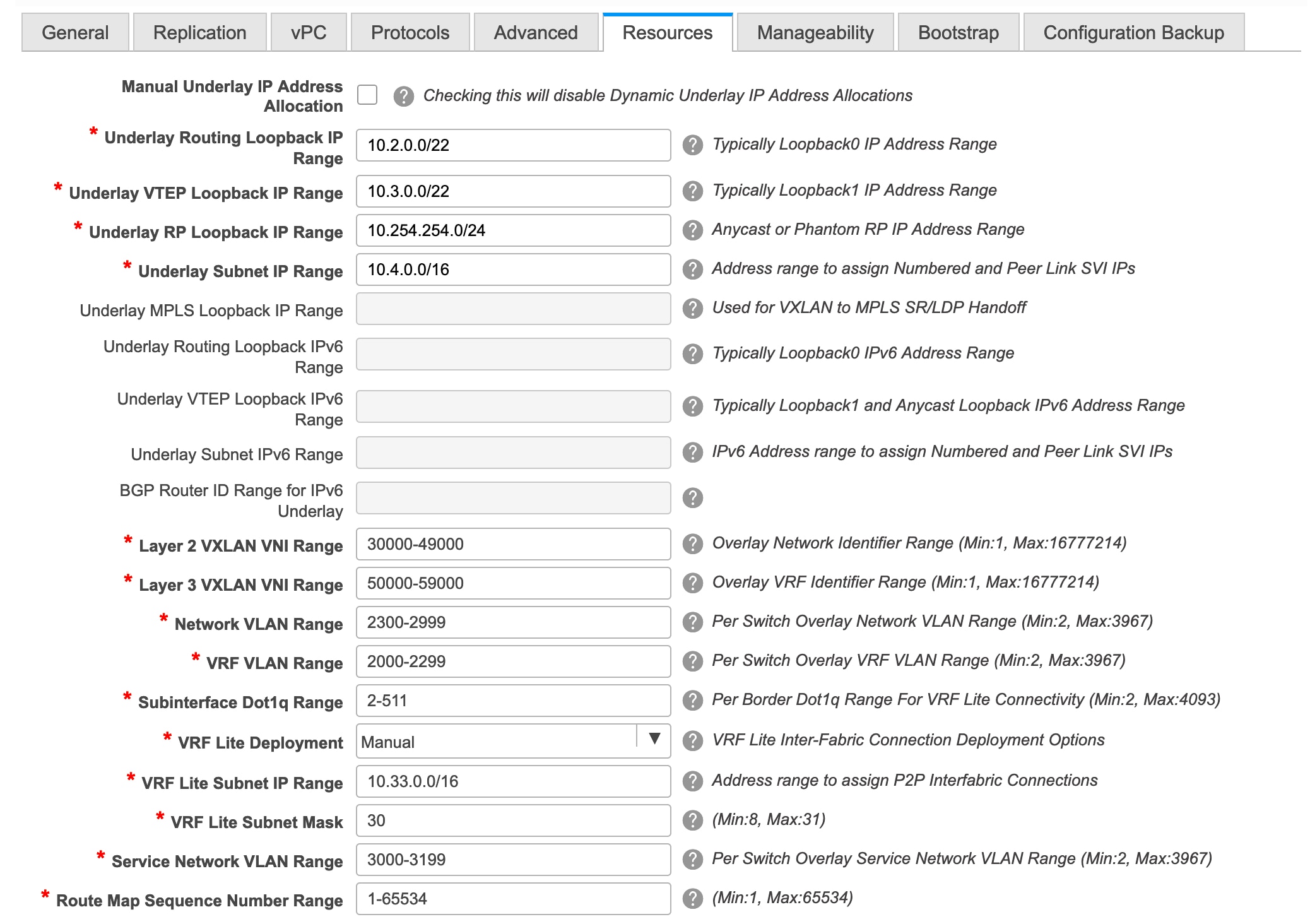
Manual Underlay IP Address Allocation – Do not select this check box if you are transitioning your VXLAN fabric management to DCNM.
-
By default, DCNM allocates the underlay IP address resources (for loopbacks, fabric interfaces, etc) dynamically from the defined pools. If you select the check box, the allocation scheme switches to static, and some of the dynamic IP address range fields are disabled.
-
For static allocation, the underlay IP address resources must be populated into the Resource Manager (RM) using REST APIs.
Refer the Cisco DCNM REST API Reference Guide, Release 11.2(1) for more details. The REST APIs must be invoked after the switches are added to the fabric, and before you use the Save & Deploy option.
-
The Underlay RP Loopback IP Range field stays enabled if BIDIR-PIM function is chosen for multicast replication.
-
Changing from static to dynamic allocation keeps the current IP resource usage intact. Only future IP address allocation requests are taken from dynamic pools.
Underlay Routing Loopback IP Range - Specifies loopback IP addresses for the protocol peering.
Underlay VTEP Loopback IP Range - Specifies loopback IP addresses for VTEPs.
Underlay RP Loopback IP Range - Specifies the anycast or phantom RP IP address range.
Underlay Subnet IP Range - IP addresses for underlay P2P routing traffic between interfaces.
Underlay MPLS Loopback IP Range: Specifies the underlay MPLS loopback IP address range.
Note that the IP range should be a unique range, that is, it should not overlap with IP ranges of the other fabrics.
Layer 2 VXLAN VNI Range and Layer 3 VXLAN VNI Range - Specifies the VXLAN VNI IDs for the fabric.
Network VLAN Range and VRF VLAN Range - VLAN ranges for the Layer 3 VRF and overlay network.
Subinterface Dot1q Range - Specifies the subinterface range when L3 sub interfaces are used.
VRF Lite Deployment - Specify the VRF Lite method for extending inter fabric connections.
If you select Manual, the VRF Lite subnet details are required so that the resource manager can reserve the address space.
If you select Back2BackOnly, ToExternalOnly, or Both, then the VRF Lite subnet fields are enabled.
VRF Lite Subnet IP Range and VRF Lite Subnet Mask – These fields are populated with the DCI subnet details. Update the fields as needed.
The values shown in your screen are automatically generated. If you want to update the IP address ranges, VXLAN Layer 2/Layer 3 network ID ranges or the VRF/Network VLAN ranges, ensure the following:
Note
When you update a range of values, ensure that it does not overlap with other ranges. You should only update one range of values at a time. If you want to update more than one range of values, do it in separate instances. For example, if you want to update L2 and L3 ranges, you should do the following.
-
Update the L2 range and click Save.
-
Click the Edit Fabric option again, update the L3 range and click Save.
Service Network VLAN Range - Specifies a VLAN range in the Service Network VLAN Range field. This is a per switch overlay service network VLAN range. The minimum allowed value is 2 and the maximum allowed value is 3967.
Route Map Sequence Number Range - Specifies the route map sequence number range. The minimum allowed value is 1 and the maximum allowed value is 65534.
-
-
Click the Manageability tab.
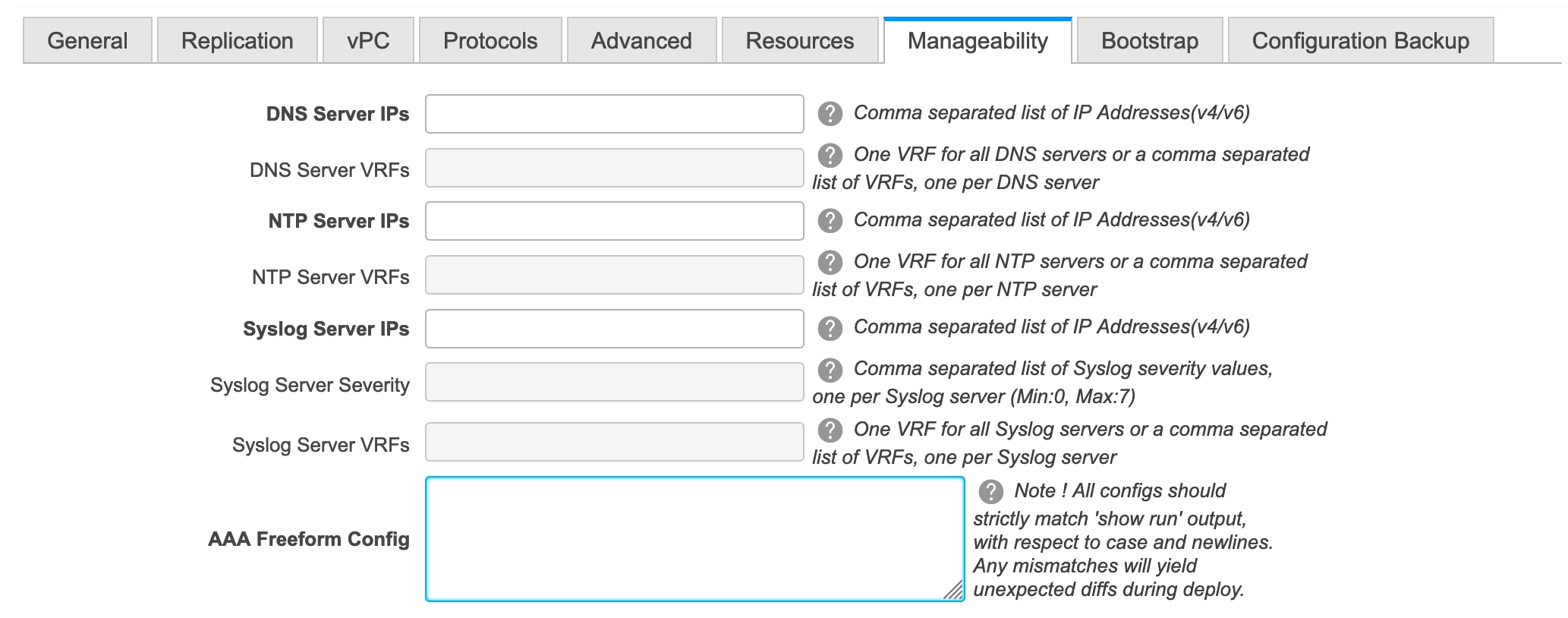
The fields in this tab are:
DNS Server IPs - Specifies the comma separated list of IP addresses (v4/v6) of the DNS servers.
DNS Server VRFs - Specifies one VRF for all DNS servers or a comma separated list of VRFs, one per DNS server.
NTP Server IPs - Specifies comma separated list of IP addresses (v4/v6) of the NTP server.
NTP Server VRFs - Specifies one VRF for all NTP servers or a comma separated list of VRFs, one per NTP server.
Syslog Server IPs – Specifies the comma separated list of IP addresses (v4/v6) IP address of the syslog servers, if used.
Syslog Server Severity – Specifies the comma separated list of syslog severity values, one per syslog server. The minimum value is 0 and the maximum value is 7. To specify a higher severity, enter a higher number.
Syslog Server VRFs – Specifies one VRF for all syslog servers or a comma separated list of VRFs, one per syslog server.
AAA Freeform Config – Specifies the AAA freeform configs.
If AAA configs are specified in the fabric settings, switch_freeform PTI with source as UNDERLAY_AAA and description as AAA Configurations will be created.
- Click the Bootstrap tab.
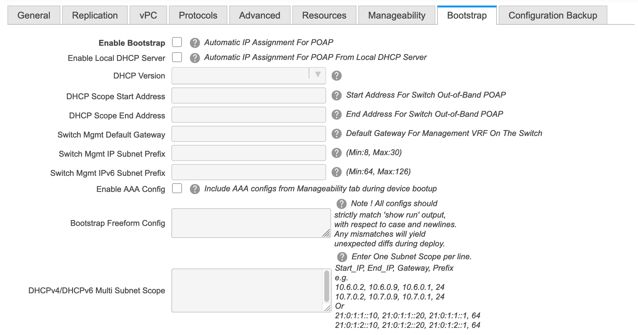
Enable Bootstrap - Select this check box to enable the bootstrap feature.
After you enable bootstrap, you can enable the DHCP server for automatic IP address assignment using one of the following methods:
-
External DHCP Server: Enter information about the external DHCP server in the Switch Mgmt Default Gateway and Switch Mgmt IP Subnet Prefix fields.
-
Local DHCP Server: Enable the Local DHCP Server checkbox and enter details for the remaining mandatory fields.
Enable Local DHCP Server - Select this check box to initiate enabling of automatic IP address assignment through the local DHCP server. When you select this check box, the DHCP Scope Start Address and DHCP Scope End Address fields become editable.
If you do not select this check box, DCNM uses the remote or external DHCP server for automatic IP address assignment.
DHCP Version – Select DHCPv4 or DHCPv6 from this drop-down list. When you select DHCPv4, the Switch Mgmt IPv6 Subnet Prefix field is disabled. If you select DHCPv6, the Switch Mgmt IP Subnet Prefix is disabled.
Note
Cisco DCNM IPv6 POAP is not supported with Cisco Nexus 7000 Series Switches. Cisco Nexus 9000 and 3000 Series Switches support IPv6 POAP only when switches are either L2 adjacent (eth1 or out-of-band subnet must be a /64) or they are L3 adjacent residing in some IPv6 /64 subnet. Subnet prefixes other than /64 are not supported.
DHCP Scope Start Address and DHCP Scope End Address - Specifies the first and last IP addresses of the IP address range to be used for the switch out of band POAP.
Switch Mgmt Default Gateway - Specifies the default gateway for the management VRF on the switch.
Switch Mgmt IP Subnet Prefix - Specifies the prefix for the Mgmt0 interface on the switch. The prefix should be between 8 and 30.
DHCP scope and management default gateway IP address specification - If you specify the management default gateway IP address 10.0.1.0 and subnet mask 24, ensure that the DHCP scope is within the specified subnet, between 10.0.1.1 and 10.0.1.254.
Switch Mgmt IPv6 Subnet Prefix - Specifies the IPv6 prefix for the Mgmt0 interface on the switch. The prefix should be between 112 and 126. This field is editable if you enable IPv6 for DHCP.
Enable AAA Config – Select this check box to include AAA configs from the Manageability tab during device bootup.
Bootstrap Freeform Config - (Optional) Enter additional commands as needed. For example, if you are using AAA or remote authentication related configurations, you need to add these configurations in this field to save the intent. After the devices boot up, they contain the intent defined in the Bootstrap Freeform Config field.
Copy-paste the running-config to a freeform config field with correct indentation, as seen in the running configuration on the NX-OS switches. The freeform config must match the running config. For more information, see Resolving Freeform Config Errors in Switches.
DHCPv4/DHCPv6 Multi Subnet Scope - Specifies the field to enter one subnet scope per line. This field is editable after you check the Enable Local DHCP Server check box.
The format of the scope should be defined as:
DHCP Scope Start Address, DHCP Scope End Address, Switch Management Default Gateway, Switch Management Subnet Prefix
For example: 10.6.0.2, 10.6.0.9, 10.6.0.1, 24
-
-
Click the Configuration Backup tab. The fields on this tab are:
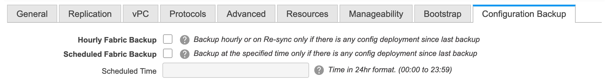
Hourly Fabric Backup: Select the check box to enable an hourly backup of fabric configurations and the intent.
You can enable an hourly backup for fresh fabric configurations and the intent as well. If there is a configuration push in the previous hour, DCNM takes a backup.
Intent refers to configurations that are saved in DCNM but yet to be provisioned on the switches.
Scheduled Fabric Backup: Check the check box to enable a daily backup. This backup tracks changes in running configurations on the fabric devices that are not tracked by configuration compliance.
Scheduled Time: Specify the scheduled backup time in a 24-hour format. This field is enabled if you check the Scheduled Fabric Backup check box.
Select both the check boxes to enable both back up processes.
The backup process is initiated after you click Save.
The backup configuration files are stored in the following path in DCNM: /usr/local/cisco/dcm/dcnm/data/archive
The number of archived files that can be retained is set in the # Number of archived files per device to be retained: field in the Server Properties window.
Note
Hourly and scheduled backup processes happen only during the next periodic configuration compliance activity, and there can be a delay of up to an hour. To trigger an immediate backup, do the following:
-
Choose Control > Fabric Builder. The Fabric Builder screen comes up.
-
Click within the specific fabric box. The fabric topology screen comes up.
-
From the Actions pane at the left part of the screen, click Re-Sync Fabric.
You can also initiate the fabric backup in the fabric topology window. Click Backup Now in the Actions pane.
-
-
Click Save after filling and updating relevant information. A note appears briefly at the bottom right part of the screen, indicating that the fabric is created. When a fabric is created, the fabric page comes up. The fabric name appears at the top left part of the screen.
(At the same time, the newly created fabric instance appears on the Fabric Builder screen. To go to the Fabric Builder screen, click the left arrow (←) button above the Actions pane [to the left of the screen]).
The Actions pane allows you to perform various functions. One of them is the Add switches option to add switches to the fabric. After you create a fabric, you should add fabric devices. The options are explained:
-
Tabular View - By default, the switches are displayed in the topology view. Use this option to view switches in the tabular view.
-
Refresh topology - Allows you to refresh the topology.
-
Save Layout – Saves a custom view of the topology. You can create a specific view in the topology and save it for ease of use.
-
Delete saved layout – Deletes the custom view of the topology
-
Topology views - You can choose between Hierarchical, Random and Custom saved layout display options.
-
Hierarchical - Provides an architectural view of your topology. Various Switch Roles can be defined that draws the nodes on how you configure your CLOS topology.
-
Random - Nodes are placed randomly on the window. DCNM tries to make a guess and intelligently place nodes that belong together in close proximity.
-
Custom saved layout - You can drag nodes around to your liking. Once you have the positions as how you like, you can click Save Layout to remember the positions. Next time you come to the topology, DCNM will draw the nodes based on your last saved layout positions.
-
-
Restore Fabric – Allows you to restore the fabric to a prior DCNM configuration state (one month back, two months back, and so on). For more information, see Restore Fabric section.
-
Backup Now: You can initiate a fabric backup manually by clicking Backup Now. Enter a name for the tag and click OK. Regardless of the settings you choose under the Configuration Backup tab in the Fabric Settings dialog box, you can initiate a backup using this option.
-
Resync Fabric - Use this option to resynchronize DCNM state when there is a large scale out-of-band change, or if configuration changes do not register in the DCNM properly. The resync operation does a full CC run for the fabric switches and recollects “show run” and “show run all” commands from the switches. When you initiate the re-sync process, a progress message is displayed on the window. During the re-sync, the running configuration is taken from the switches. Then, the OUT-OF-SYNC/IN-SYNC status for the switch is recalculated based on the intent or expected configuration defined in DCNM versus the current running configuration that was taken from the switches.
-
Add Switches – Allows you to add switch instances to the fabric.
-
Fabric Settings – Allows you to view or edit fabric settings.
-
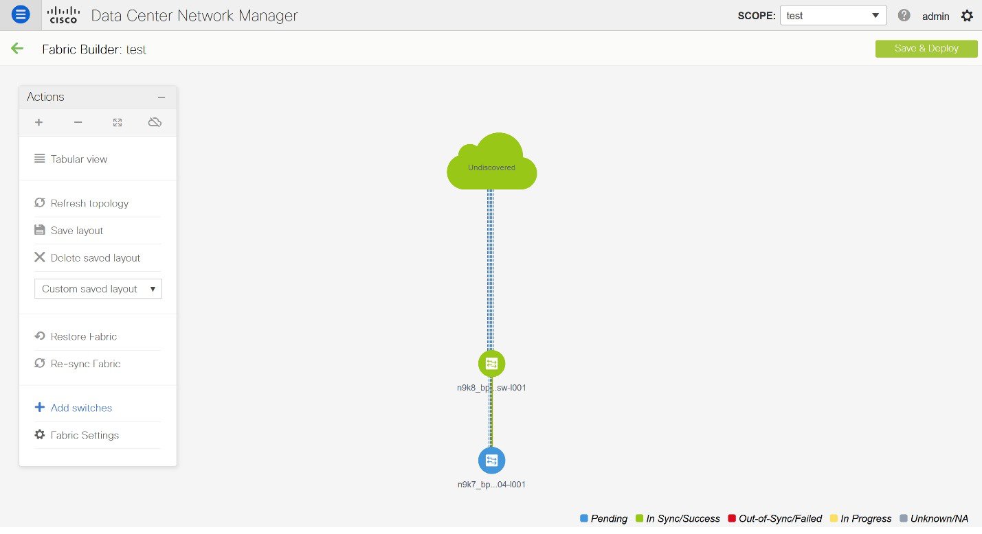
Cloud icon - Click the Cloud icon to display (or not display) an Undiscovered cloud.
When you click the icon, the Undiscovered cloud and its links to the selected fabric topology are not displayed.
Click the Cloud icon again to display the Undiscovered cloud.
-
SCOPE - You can toggle between fabrics by using the SCOPE drop-down box at the top right. The current fabric is highlighted. An MSD and its member fabrics are distinctly displayed, wherein the member fabrics are indented, under the MSD fabric.
Adding Switch Instances to the Fabric
Networks and VRFs can be extended (and hence can be common) across fabrics. However, switches in each fabric are unique, and hence, each switch can only be added to one fabric.
Click the Add Switches option from the Actions panel to add switches to the fabric created in DCNM. The Inventory Management screen comes up. The screen contains two tabs, one for discovering existing switches and the other for discovering new switches. Both options are explained.
Discovering Existing Switches
-
Use the Discover Existing Switches tab to add an existing switch. In this case, a switch with known credentials is added to the standalone fabric. The IP address (Seed IP), administrator username, and password (Username and Password fields) of the switch are keyed.
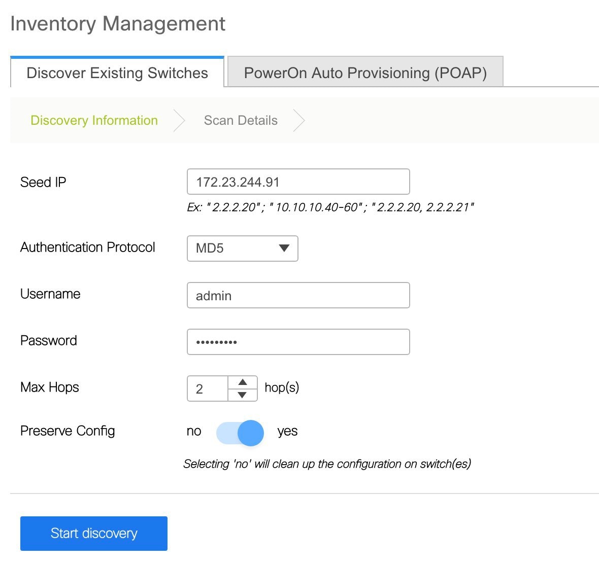
-
Click Start discovery. The Scan Details window comes up shortly. Since the Max Hops field was populated with 2, the switch with the specified IP address (leaf-91) and switches two hops from it are populated in the Scan Details window.
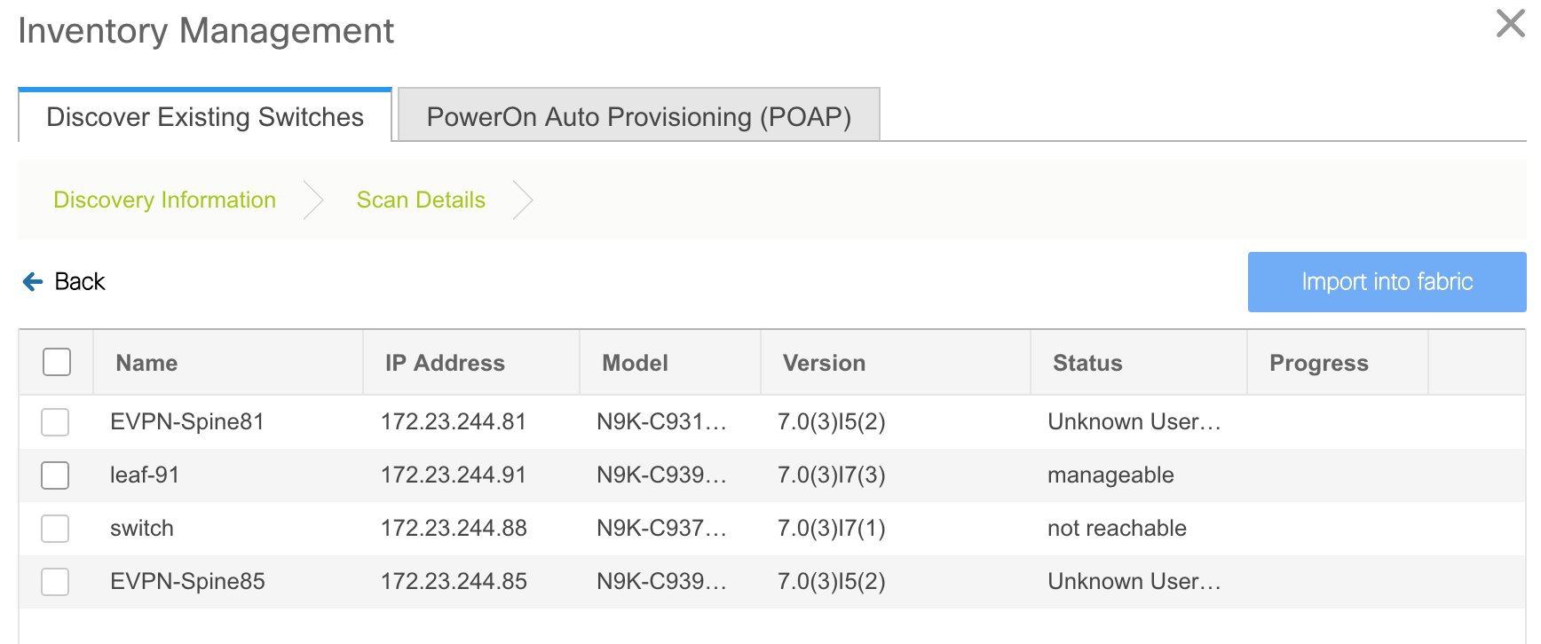
-
Check the check box next to the concerned switch and click Import into fabric.
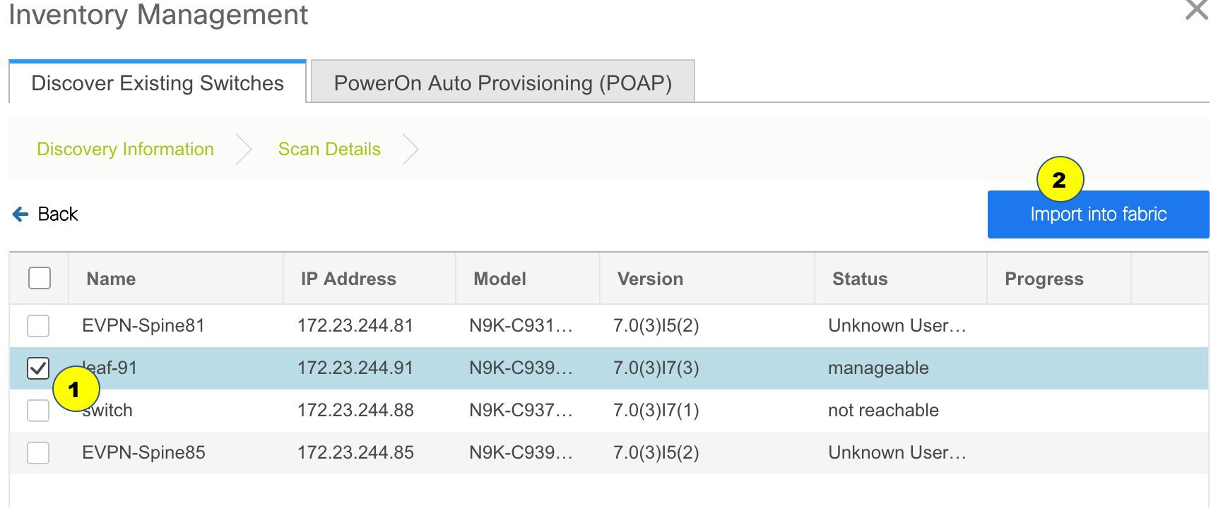
Though this example describes the discovery of one switch, it is a best practice to discover multiple switches at once. The switches must be properly cabled and connected to the DCNM server and the switch status must be manageable.
The switch discovery process is initiated. The Progress column displays progress for all the selected switches. It displays done for each switch on completion.
Note
You must not close the screen (and try to add switches again) until all selected switches are imported or an error message comes up.
If an error message comes up, close the screen. The fabric topology screen comes up. The error messages are displayed at the top right part of the screen. Resolve the errors wherever applicable and initiate the import process again by clicking Add Switches in the Actions panel.
After DCNM discovers all the switches, and the Progress column displays done for all switches, close the screen. The Standalone fabric topology screen comes up again. The switch icons of the added switches are displayed in it.
Note
You will encounter the following errors during switch discovery sometimes.Discovery error - The switch discovery process might fail for a few switches, and the Discovery Error message displayed. However, such switches are displayed in the fabric topology. You must remove such switches from the fabric (right-click the switch icon and click Discovery > Remove from fabric), and import them again.
Device connectivity issue: Before proceeding further, wait for ten minutes for the switch-internal processes to complete. Else, you might encounter a device connectivity failure message at a later stage.
-
Click Refresh topology to view the latest topology view.
When all switches are added and roles assigned to them, the fabric topology contains the switches and connections between them.
-
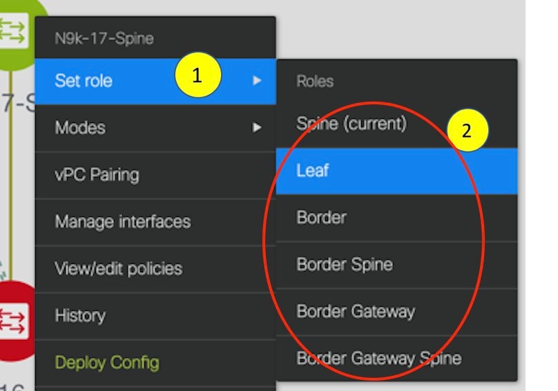
After discovering the switches, assign the fabric role to each switch. Since each switch is assigned the leaf role by default, assign other roles as needed. Right click the switch, and use the Set role option to set the appropriate role.
Note
-
Starting from DCNM 11.1(1), switch roles can be changed if there are no overlays on the switches, but only as per the list of allowed switch role changes given at Switch Operations.
-
After you upgrade to Cisco DCNM Release 11.1(1) with an existing fabric with the Easy_Fabric template, you cannot set the Border Spine or Border Gateway Spine roles to switches, because these roles are not supported with the Easy_Fabric template. You need to use the Easy_fabric_11_1 template to set these roles for switches in a fabric.
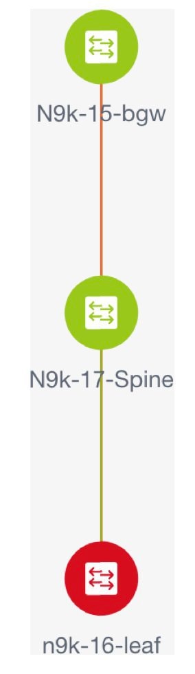
If you choose the Hierarchical layout for display (in the Actions panel), the topology automatically gets aligned as per role assignment, with the leaf switches at the bottom, the spine switches connected on top of them, and the border switches at the top.
Note
To connect fabrics using the EVPN Multi-Site feature, you must change the role of the designated BGW to Border Gateway or Border Gateway Spine. To connect fabrics using the VRF Lite feature, you must change the role of the border leaf switch to Border or Border Spine. If you want to deploy VRF Lite and EVPN Multi-Site features in a fabric, you must set the device role to Border Gateway or Border Gateway Spine and provision VRF Lite and Multi-Site features. If you do not update border device roles correctly at this stage, then you will have to remove the device from the fabric and discover it again through DCNM using the POAP bootstrap option and reprovision the configurations for the device.
Assign vPC switch role - To designate a pair of switches as a vPC switch pair, right-click the switch and choose the vPC peer switch from the list of switches.
Note
vPC support is added for BGWs in the DCNM 11.1(1) release.
AAA server password - During fabric creation, if you have entered AAA server information (in the Manageability tab), you must update the AAA server password on each switch. Else, switch discovery fails.
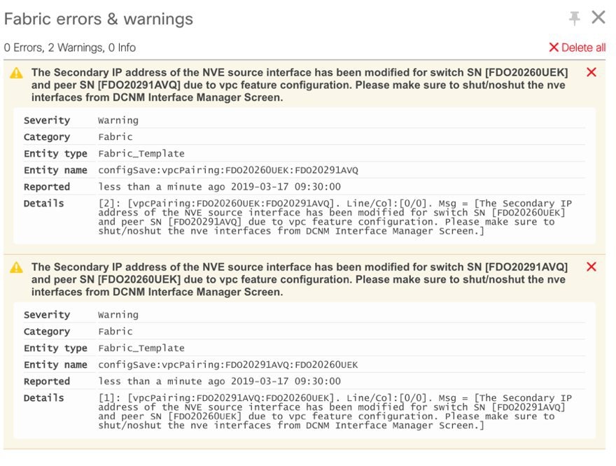
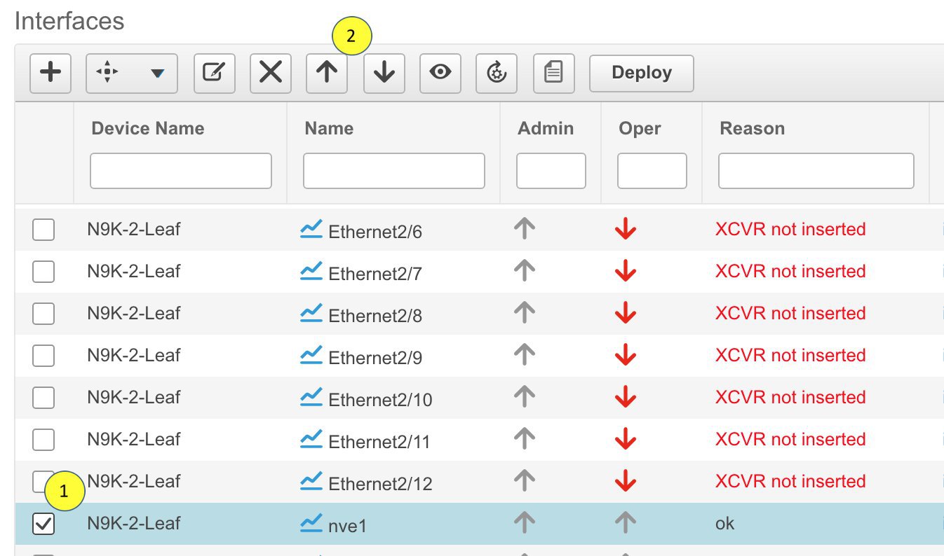
When you enable or disable a vPC setup or the advertise-pip option, or update Multi-Site configuration, you should use the Save & Deploy operation. At the end of the operation, an error prompts you to configure the shutdown or no shutdown command on the nve interface. A sample error screenshot when you enable a vPC setup:
To resolve, go to the Control > Interfaces screen and deploy the No Shutdown or Shutdown configuration on the nve interface (nve1 in the screenshot).
Click Save & Deploy in the Fabric Builder topology screen again to complete the task.
If the non-overlay SVIs are captured in the DCNM intent while the switch is in the standalone mode, and then the switch becomes a part of a vPC pair, the switch generates the following configuration:
no ip redirects
no ipv6 redirects
To avoid a diff from the configuration compliance in DCNM, you must update the intent with the same config.
When a new vPC pair is created and deployed successfully using Cisco DCNM, one of the peers might be out-of-sync for the no ip redirects CLI even if the command exists on the switch. This out-of-sync is due to a delay on the switch to display the CLI in the running configuration, which causes a diff in the configuration compliance. Re-sync the switches in the Config Deployment window to resolve the diff.
-
-
Click Save & Deploy at the top right part of the screen.
The template and interface configurations form the underlay network configuration on the switches. Also, freeform CLIs that were entered as part of fabric settings (leaf and spine switch freeform configurations entered in the Advanced tab) are deployed. Refer the Freeform Configurations on Fabric Switches section for more details on freeform configurations.
Configuration Compliance: If the provisioned configurations and switch configurations do not match, the Status column displays out-of-sync. For example, if you enable a function on the switch manually through a CLI, then it results in a configuration mismatch.
To ensure configurations provisioned from DCNM to the fabric are accurate or to detect any deviations (such as out-of-band changes), DCNM’s Configuration Compliance engine reports and provides necessary remediation configurations.
When you click Save & Deploy, the Config Deployment window appears.
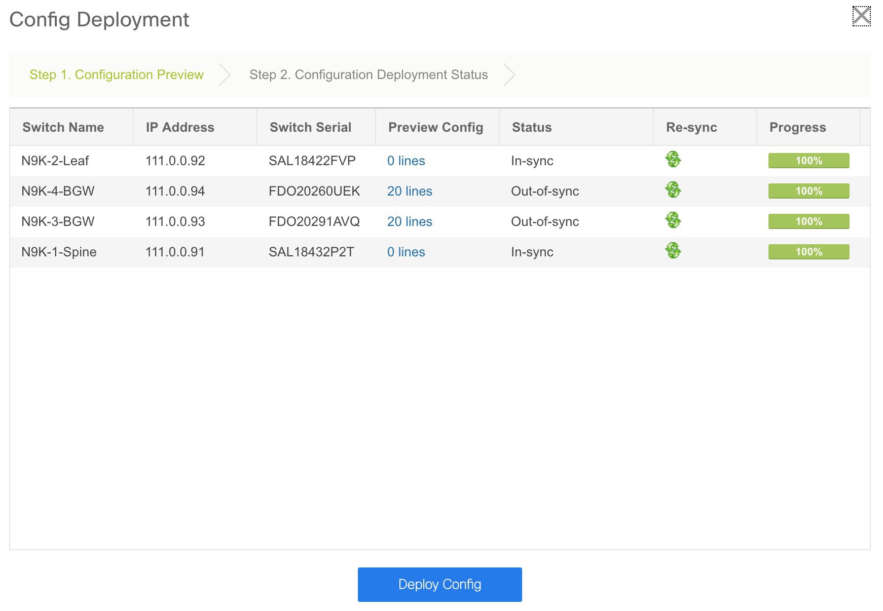
If the status is out-of-sync, it suggests that there is inconsistency between the DCNM and configuration on the device.
The Re-sync button is displayed for each switch in the Re-sync column. Use this option to resynchronize DCNM state when there is a large scale out-of-band change, or if configuration changes do not register in the DCNM properly. The re-sync operation does a full CC run for the switch and recollects “show run” and “show run all” commands from the switch. When you initiate the re-sync process, a progress message is displayed on the screen. During the re-sync, the running configuration is taken from the switch. The OUT-OF-SYNC/IN-SYNC status for the switch is recalculated based on the intent defined in DCNM.
Click the Preview Config column entry (updated with a specific number of lines). The Config Preview screen comes up.
The Pending Config tab displays the pending configurations for successful deployment.
The Side-by-side Comparison tab displays the current configurations and expected configurations together.
Note that multi-line banner configuration support is available in Cisco DCNM Release 11.1(1).
In DCNM 11.0, Configuration Compliance only supports single-line banner motd configuration. In DCNM 11.1, multi-line banner motd configuration is supported. Multi-line banner motd configuration can be configured in DCNM with freeform configuration policy, either per switch using switch_freeform, or per fabric using leaf/spine freeform configuration. Note that after the multi-line banner motd is configured, deploy the policy by executing the Save & Deploy option in the (top right part of the) fabric topology screen. Else, the policy may not be deployed properly on the switch. The banner policy is only to configure single-line banner configuration. Also, you can only create one banner related freeform configuration/policy. Multiple policies for configuring banner motd is not supported.
-
Close the screen.
In the Configuration Deployment screen, click Deploy Config at the bottom part of the screen to initiate pending configuration onto the switch. The Status column displays FAILED or SUCCESS state. For a FAILED status, investigate the reason for failure to address the issue.
After successful configuration provisioning (when all switches display a progress of 100%), close the screen.
The fabric topology is displayed. The switch icons turn green to indicate successful configuration.
If a switch icon is in red color, it indicates that the switch and DCNM configurations are not in sync. When deployment is pending on a switch, the switch is displayed in blue color. From DCNM 11.3(1), the pending state indicates that there is a pending deployment or pending recomputation. You can click on the switch and review the pending deployments using Preview or Deploy Config options, or click Save & Deploy to recompute the state of the switch.
Note
If there are any warning or errors in the CLI execution, a notification will appear in the Fabric builder window. Warnings or errors that are auto-resolvable have the Resolve option.
You can right click the switch icon and update switch related settings.
SCOPE: You can toggle between fabrics by using the SCOPE drop-down list at the top right part of the screen. By default, the current fabric is highlighted. An MSD and its member fabrics are distinctly displayed, wherein the member fabrics are indented under the MSD fabric.
You can use Save & Deploy for single and multiple switches. Add switches and then click Save & Deploy to ensure configuration compliance. Whether discovering multiple switches at once or one by one, as a best practice, use Save & Deploy and not the Deploy Config option (accessible after right-clicking the switch icon).
When a leaf switch boots up after a switch reload or RMA operation, DCNM provisions configurations for the switch and FEX devices connected to it. Occasionally, FEX connectivity comes up after DCNM provisions FEX (host interface) configurations, resulting in a configuration mismatch. To resolve the mismatch, click Save & Deploy again in the fabric topology screen.
An example of the Deploy Config option usage is for switch-level freeform configurations. Refer the Freeform Configurations on Fabric Switches topic for details.
The Configuration Compliance function and principles are applicable for discovering existing and new switches. New switch discovery in DCNM (through a simplified POAP process) is explained next.
Discovering New Switches
-
Power on the new switch in the external fabric after ensuring that it is cabled to the DCNM server. Boot the Cisco NX-OS and setup switch credentials.
-
Execute the write erase and reload commands on the switch.
Choose Yes to both the CLI commands that prompt you to choose Yes or No.
-
Set the boot variable to the image that you want to POAP. DCNM uses this image to POAP. Also, DCNM injects an information script into the switch to collect the device onboarding information.
-
In the DCNM GUI, go to a standalone fabric (Click Control > Fabric Builder and click a standalone fabric). The fabric topology is displayed.
Note
If you want to POAP with DHCP, make sure that DHCP is enabled on the fabric settings. Click Fabric Settings and edit the DHCP information in the Bootstrap tab.
-
Go to the fabric topology window and click the Add switches option from the Actions panel. The Inventory Management window comes up.
-
Click the POAP tab.
In an earlier step, the reload command was executed on the switch. When the switch restarts to reboot, DCNM retrieves the serial number, model number, and version from the switch and displays them on the Inventory Management along window. Also, an option to add the IP address, hostname, and password are made available. If the switch information is not retrieved, refresh the window.
Note
At the top left part of the window, export and import options are provided to export and import the .csv file that contains the switch information. You can pre-provision devices using the import option as well.
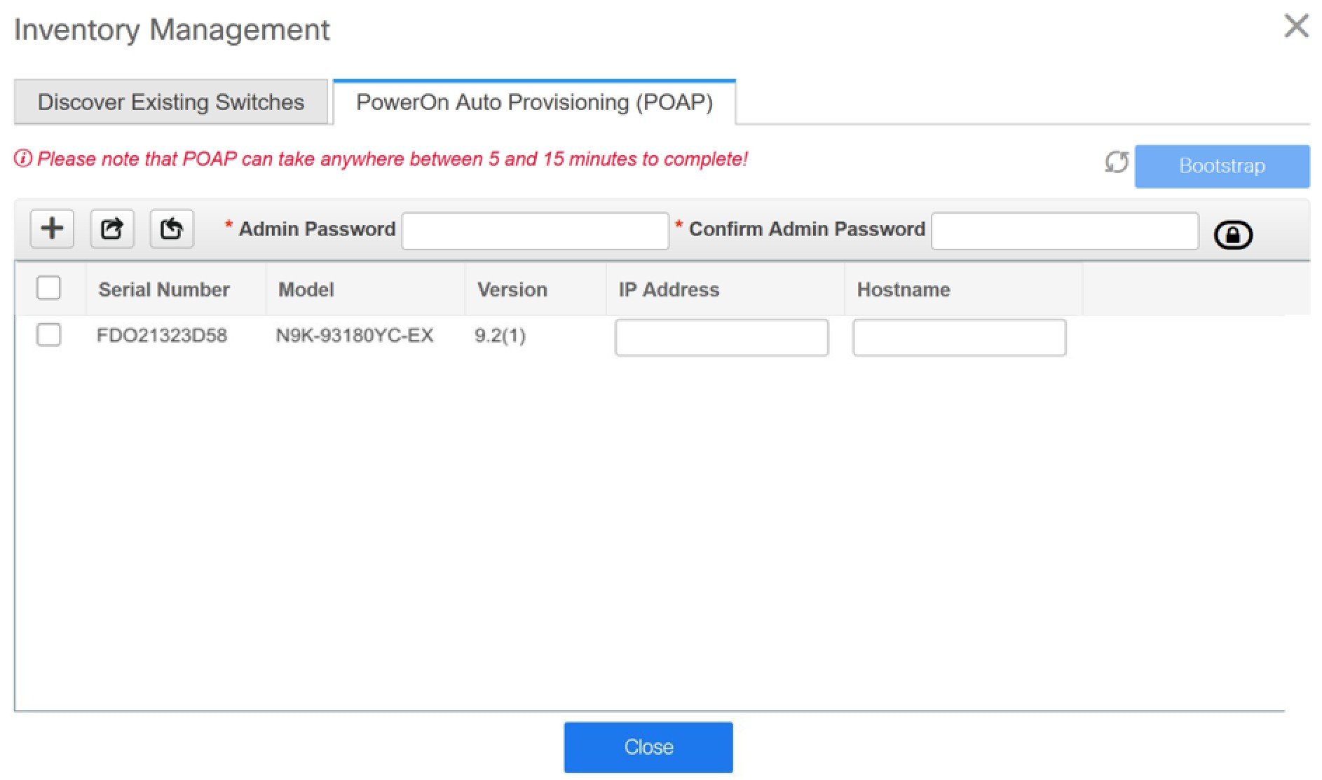
Select the checkbox next to the switch and add switch credentials: IP address and host name.
Based on the IP address of your device, you can either add the IPv4 or IPv6 address in the IP Address field.
Beginning with Release 11.2(1), you can provision devices in advance. To pre-provision devices, refer to Pre-provisioning a Device.
-
In the Admin Password and Confirm Admin Password fields, enter and confirm the admin password.
This admin password is applicable for all the switches displayed in the POAP window.
Note
If you do not want to use admin credentials to discover switches, you can instead use the AAA authentication, that is, RADIUS or TACACS credentials for discovery only.
-
(Optional) Use discovery credentials for discovering switches.
-
Click the Add Discovery Credentials icon to enter the discovery credentials for switches.
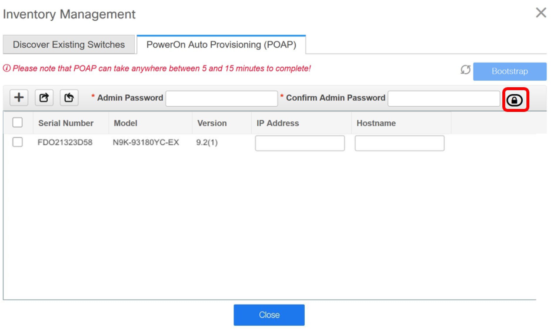
-
In the Discovery Credentials window, enter the discovery credentials such as discovery username and password.
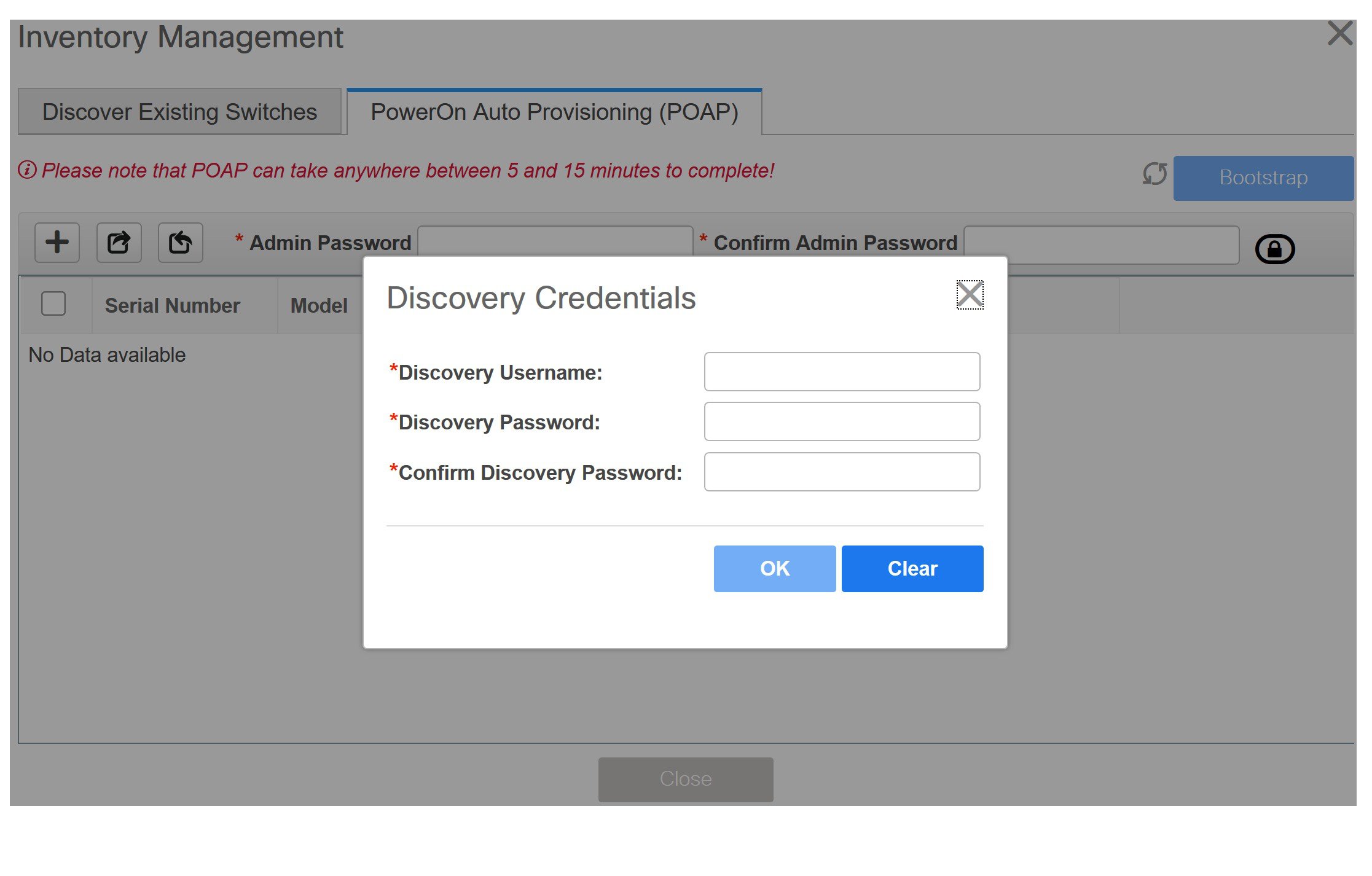
Click OK to save the discovery credentials.
If the discovery credentials are not provided, DCNM uses the admin user and password to discover switches.
Note
-
The discovery credentials that can be used are AAA authentication based credentials, that is, RADIUS or TACACS.
-
The discovery credential is not converted as commands in the device configuration. This credential is mainly used to specify the remote user (or other than the admin user) to discover the switches. If you want to add the commands as part of the device configuration, add them in the Bootstrap Freeform Config field under the Bootstrap tab in the fabric settings. Also, you can add the respective policy from View/Edit Policies window.
-
-
-
Click Bootstrap at the top right part of the screen.
DCNM provisions the management IP address and other credentials to the switch. In this simplified POAP process, all ports are opened up.
-
Click Refresh Topology to get updated information. The added switch goes through the POAP cycle. Monitor and check the switch for POAP completion.
-
After the added switch completes POAP, the fabric builder topology page is refreshed with the added switch with some physical connections. However, the switch icon is in red color indicating that the fabric is Out-Of-Sync and you must click Save & Deploy on the fabric builder topology to deploy pending configurations (such as template and interface configurations) onto the switches.
Note
For any changes on the fabric that results in the out-of-sync, then you must deploy the changes. The process is the same as explained in the Discovering Existing Switches section.
During fabric creation, if you have entered AAA server information (in the Manageability tab), you must update the AAA server password on each switch. Else, switch discovery fails.
-
After the pending configurations are deployed, the Progress column displays 100% for all switches.
-
Click Close to return to the fabric builder topology.
-
Click Refresh Topology to view the update. All switches must be in green color indicating that they are functional.
-
The switch and the link are discovered in DCNM. Configurations are built based on various policies (such as fabric, topology, and switch generated policies). The switch image (and other required) configurations are enabled on the switch.
-
In the DCNM GUI, the discovered switches can be seen in the Standalone fabric topology. Up to this step, the POAP is completed with basic settings. All the interfaces are set to trunk ports. You must setup interfaces through the Control > Interfaces option for any additional configurations, but not limited to the following:
-
vPC pairing.
-
Breakout interfaces.
-
Port channels, and adding members to ports.
When you enable or disable a vPC setup or the advertise-pip option, or update Multi-Site configuration, you should use the Save & Deploy operation. At the end of the operation, an error prompts you to configure the shutdown or no shutdown command on the nve interface. A sample error screenshot when you enable a vPC setup:
To resolve, go to the Control > Interfaces screen and deploy the No Shutdown or Shutdown configuration on the nve interface.
Click Save & Deploy in the Fabric Builder topology screen again to complete the task.
-
Note |
|
You can right-click the switch to view various options:
-
Set Role - Assign a role to the switch (Spine, Border Gateway, and so on).
Note
-
Changing of the switch role is allowed only before executing Save & Deploy.
-
Starting from DCNM 11.1(1), switch roles can be changed if there are no overlays on the switches, but only as per the list of allowed switch role changes given at Switch Operations.
-
After you upgrade to Cisco DCNM Release 11.1(1) with an existing fabric with the Easy_Fabric template, you cannot set the Border Spine or Border Gateway Spine roles to switches, because these roles are not supported with the Easy_Fabric template. You need to use the Easy_fabric_11_1 template to set these roles for switches in a fabric.
-
-
Modes - Maintenance and Active/Operational modes.
-
vPC Pairing - Select a switch for vPC and then select its peer.
You can create a virtual link for a vPC pair or change the existing physical link to a virtual link for a vPC pair.
-
Manage Interfaces - Deploy configurations on the switch interfaces.
-
View/Edit Policies - See switch policies and edit them as required.
-
History - View per switch deployment history.
-
Preview Config - View the pending configuration and the side-by-side comparison of the running and expected configuration.
-
Deploy Config - Deploy per switch configurations.
-
Discovery - You can use this option to update the credentials of the switch, reload the switch, rediscover the switch, and remove the switch from the fabric.
The new fabric is created, the fabric switches are discovered in DCNM, the underlay networks provisioned on those switches, and the configurations between DCNM and the switches are synced. The remaining tasks are:
-
Provision interface configurations such as vPCs, loopback interface, and subinterface configurations. [Interfaces topic].
-
Create overlay networks and VRFs and deploy them on the switches. [Networks and VRFs Creation and Deployment section].
Pre-provisioning a Device
Note |
Ensure that you enter DHCP details in the Bootstrap tab in the fabric settings. |
-
The pre-provisioned devices support the following configurations in DCNM:
-
Base management
-
vPC Pairing
-
Intra-Fabric links
-
Interface breakout configuration
-
-
The pre-provisioned devices do not support the following configurations in DCNM:
-
Inter-Fabric links
-
Host ports
-
vPCs to the access switches or hosts
-
FEX
-
Overlay network configurations
-
-
When a device is being pre-provisioned has breakout links, you need to specify the corresponding breakout command along with the switch's model and gateway in the Data field in the Add a new device to pre-provisioning window in order to generate the breakout PTI.
Note the following guidelines:
-
Multiple breakout commands can be separated by a semicolon (;).
-
The definitions of the fields in the data JSON object are as follows:
-
modulesModel: (Mandatory) Specifies the switch module’s model information.
-
gateway: (Mandatory) Specifies the default gateway for the management VRF on the switch. This field is required to create the intent to pre-provision devices. You need to enter the gateway even if it is in the same subnet as DCNM to create the intent as part of pre-provisioning a device.
-
breakout: (Optional) Specifies the breakout command provided in the switch.
-
portMode: (Optional) Specifies the port mode of the breakout interface.
-
The examples of the values in the Data field are as follows:
-
{"modulesModel": ["N9K-C93180LC-EX"], "gateway": "10.1.1.1/24"}
-
{"modulesModel": ["N9K-C93180LC-EX"],"breakout": "interface breakout module 1 port 1 map 10g-4x", "portMode": "hardware profile portmode 4x100G+28x40G", "gateway": "172.22.31.1/24" }
-
{"modulesModel": ["N9K-X9736C-EX", "N9K-X9732C-FX", "N9K-C9516-FM-E2", "N9K-C9516-FM-E2", "N9K-C9516-FM-E2", "N9K-C9516-FM-E2", "N9K-SUP-B+", "N9K-SC-A", "N9K-SC-A"], "gateway": "172.22.31.1/24"}
-
{"breakout":"interface breakout module 1 port 50 map 10g-4x" , "gateway": "172.16.1.1/24", "modulesModel": ["N9K-C93180YC-EX "]}
-
{"modulesModel": ["N9K-X9732C-EX", "N9K-X9732C-EX", "N9K-C9504-FM-E", "N9K-C9504-FM-E", "N9K-SUP-B", "N9K-SC-A", "N9K-SC-A"], "gateway": "172.29.171.1/24", "breakout":"interface breakout module 1 port 1,11,19 map 10g-4x; interface breakout module 1 port 7 map 25g-4x"}
-
Procedure
| Step 1 |
1. Click Control > Fabric Builder. The Fabric Builder screen is displayed. |
||
| Step 2 |
Click within the fabric box. |
||
| Step 3 |
From the Actions panel, click the Add switches option. The Inventory Management screen is displayed. |
||
| Step 4 |
Click the POAP tab. |
||
| Step 5 |
In the POAP tab, do the following:
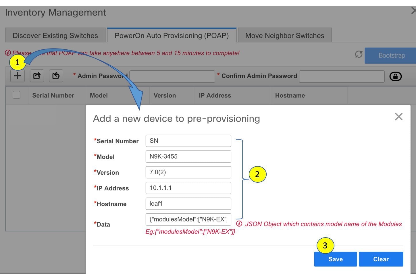 IP Address: Specify the IPv4 or IPv6 address of the new device. For information about the Data field, see the examples provided in guidelines. The device details appear in the POAP screen. You can add more devices for pre-provisioning. At the top left part of the window, Export and Import icons are provided to export and import the .csv file that contains the switch information. Using the Import option, you can pre-provision multiple devices. Add new devices’ information in the .csv file with all the mandatory fields (SerialNumber, Model, version, IpAddress, Hostname and Data fields [JSON Object]). The Data column consists of the model name of the module to identify the hardware type from the fabric template. A .csv file screenshot: 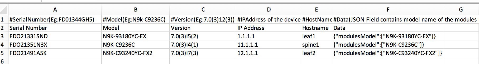 |
||
| Step 6 |
Enter the administration password in the Admin Password and Confirm Admin Password fields. |
||
| Step 7 |
Select the device(s) and click Bootstrap at the top right part of the screen. 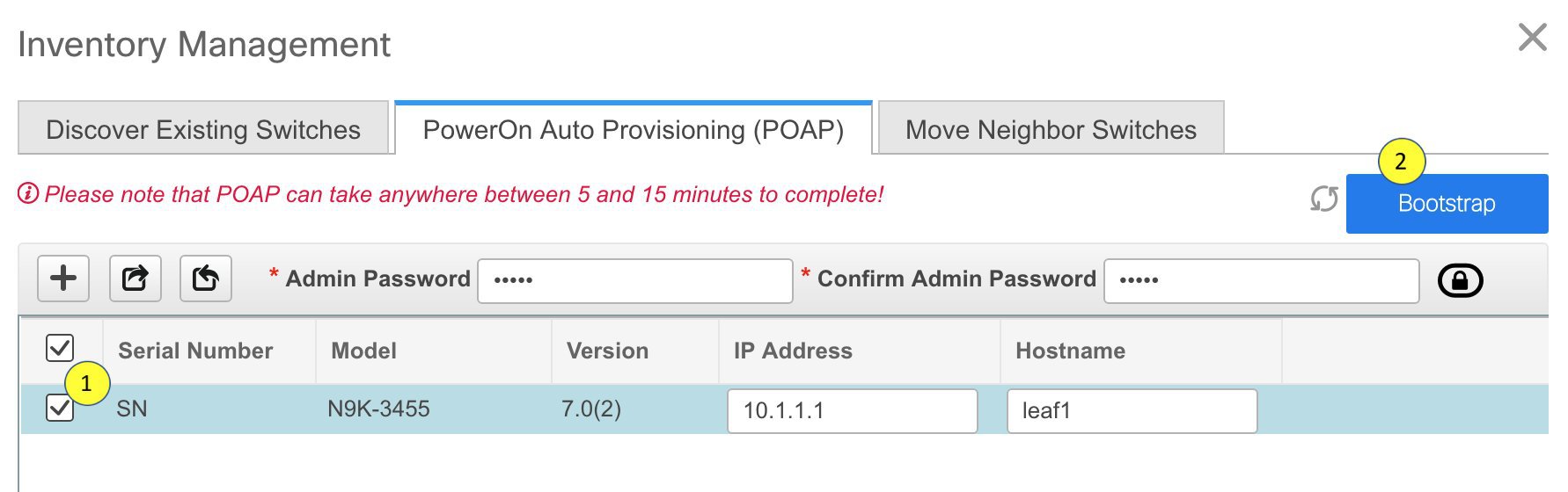 The leaf1 device appears in the external fabric topology. From the Actions panel, click Tabular View. You cannot deploy the fabric till the status of all the pre-provisioned switch(es) are displayed as ok under the Discovery Status column.
You need to click Save & Deploy in the fabric after the switch(es) are online to provision the host ports. This action must be performed before overlays are provisioned for the host port attachment. 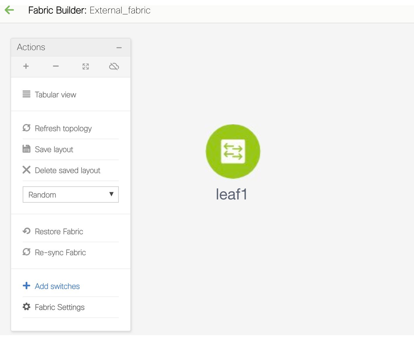 This is a representation of the leaf1 switch. When you connect leaf1 to the fabric, the switch is provisioned with the IP address 10.1.1.1. |
Precision Time Protocol for Easy Fabric
In the fabric settings for the Easy_Fabric_11_1 template, select the Enable Precision Time Protocol (PTP) check box to enable PTP across a fabric. When you select this check box, PTP is enabled globally and on core-facing interfaces. Additionally, the PTP Loopback Id and PTP Domain Id fields are editable.
The PTP feature works only when all the devices in a fabric are cloud-scale devices. Warnings are displayed if there are non-cloud scale devices in the fabric, and PTP is not enabled. The cloud-scale devices are Cisco Nexus 93180YC-EX, Cisco Nexus 93180YC-FX, Cisco Nexus 93240YC-FX2, and Cisco Nexus 93360YC-FX2 switches.
For LAN fabric deployments, specifically in a VXLAN EVPN based fabric deployments, you have to enable PTP globally, and also enable PTP on core-facing interfaces. The interfaces could be configured to the external PTP server like a VM or Linux-based machine. Therefore, the interface should be edited to have a connection with the grandmaster clock.
It is recommended that the grandmaster clock should be configured outside of Easy Fabric and it is IP reachable. The interfaces toward the grandmaster clock need to be enabled with PTP via the interface freeform config.
All core-facing interfaces are auto-enabled with the PTP configuration after you click Save & Deploy. This action ensures that all devices are PTP synced to the grandmaster clock. Additionally, for any interfaces that are not core-facing, such as interfaces on the border devices and leafs that are connected to hosts, firewalls, service-nodes, or other routers, the ttag related CLI must be added. The ttag is added for all traffic entering the VXLAN EVPN fabric and the ttag must be stripped when traffic is exiting this fabric.
Here is the sample PTP configuration:
feature ptp

ptp source 100.100.100.10 -> IP address of the loopback interface (loopback0) that is already created or user created loopback interface in the fabric settings

ptp domain 1 -> PTP domain ID specified in fabric settings

interface Ethernet1/59 -> Core facing interface
  ptp

interface Ethernet1/50 -> Host facing interface
  ttag
  ttag-strip
The following guidelines are applicable for PTP:
-
The PTP feature can be enabled in a fabric when all the switches in the fabric have Cisco NX-OS Release 7.0(3)I7(1) or a higher version. Otherwise, the following error message is displayed:
PTP feature can be enabled in the fabric, when all the switches have NX-OS Release 7.0(3)I7(1) or higher version. Please upgrade switches to NX-OS Release 7.0(3)I7(1) or higher version to enable PTP in this fabric.
-
For hardware telemetry support in NIR, the PTP configuration is a prerequisite.
-
If you are adding a non-cloud scale device to an existing fabric which contains PTP configuration, the following warning is displayed:
TTAG is enabled fabric wide, when all devices are cloud scale switches so it cannot be enabled for newly added non cloud scale device(s).
-
If a fabric contains both cloud scale and non-cloud scale devices, the following warning is displayed when you try to enable PTP:
TTAG is enabled fabric wide, when all devices are cloud scale switches and is not enabled due to non cloud scale device(s).
Support for Super Spine Role in DCNM
Super Spine is a device that is used for interconnecting multiple spine-leaf PODs. Prior to the DCNM Release 11.3(1), it was possible to interconnect multiple VXLAN EVPN Easy fabrics via super spines. However, these super spines had to be part of an external fabric. Within each Easy Fabric, an appropriate IGP is used for underlay connectivity. eBGP between the super spine layer in the external fabric and spine layer in the Easy Fabrics would be the recommended way of interconnecting multiple VXLAN EVPN Easy Fabrics. The eBGP peering can be configured via inter-fabric links or an appropriate mix of interface and eBGP configuration on the respective switches.
From DCNM Release 11.3(1), you have an extra interconnectivity option with super spines. You can have multiple spine-leaf PODs within the same Easy Fabric that are interconnected via super spines such that the same IGP domain extends across all the PODs, including the super spines. Within such a deployment, the BGP RRs and RPs (if applicable) are provisioned on the super spine layer. The spine layer becomes a pseudo interconnect between the leafs and super spines. VTEPs may be optionally hosted on the super spines if they have the border functionality.
The following Super Spine roles are supported in DCNM:
-
Super Spine
-
Border Super Spine
-
Border Gateway Super Spine
A border super spine handles multiple functionalities including the functionalities of a super spine, RR, RP (optionally), and a border leaf. Similarly, a border gateway super spine serves a super spine, RR, RP (optional), and a border gateway. It’s not recommended to overload border functionality on the super spine or RR layer. Instead, attach border leafs or border gateways to the super spine layer for external connectivity. The super spine layer serves as the interconnect with the RR or RP functionality.
The following are the characteristics of super spine switch roles in DCNM:
-
Supported only for the Easy_Fabric_11_1 template.
-
Can only connect to spines and borders. The valid connections are:
-
Spines to super spines
-
Spines to border super spines and border GW super spines
-
Super spines, border super spine, border GW super spine to border leafs and border GW leafs
-
-
RR or RP should always be configured on super spines if they are present in a fabric. The number of RRs and RPs supported on super spines are 4.
-
Border Super Spine and Border GW Super Spine roles are supported for inter-fabric connections.
-
vPC configurations aren’t supported on super spines.
-
Super spines don’t support IPv6 underlay configuration.
-
During the Brownfield import of switches, if a switch has the super spine role, the following error is displayed:
Serial number: [super spine/border super spine/border gateway superspine] Role isn’t supported with preserved configuration yes option.
Supported Topologies for Super Spine Switches
DCNM supports the following topologies with super spine switches.
Topology 1: Super Spine Switches in a Spine Leaf Topology
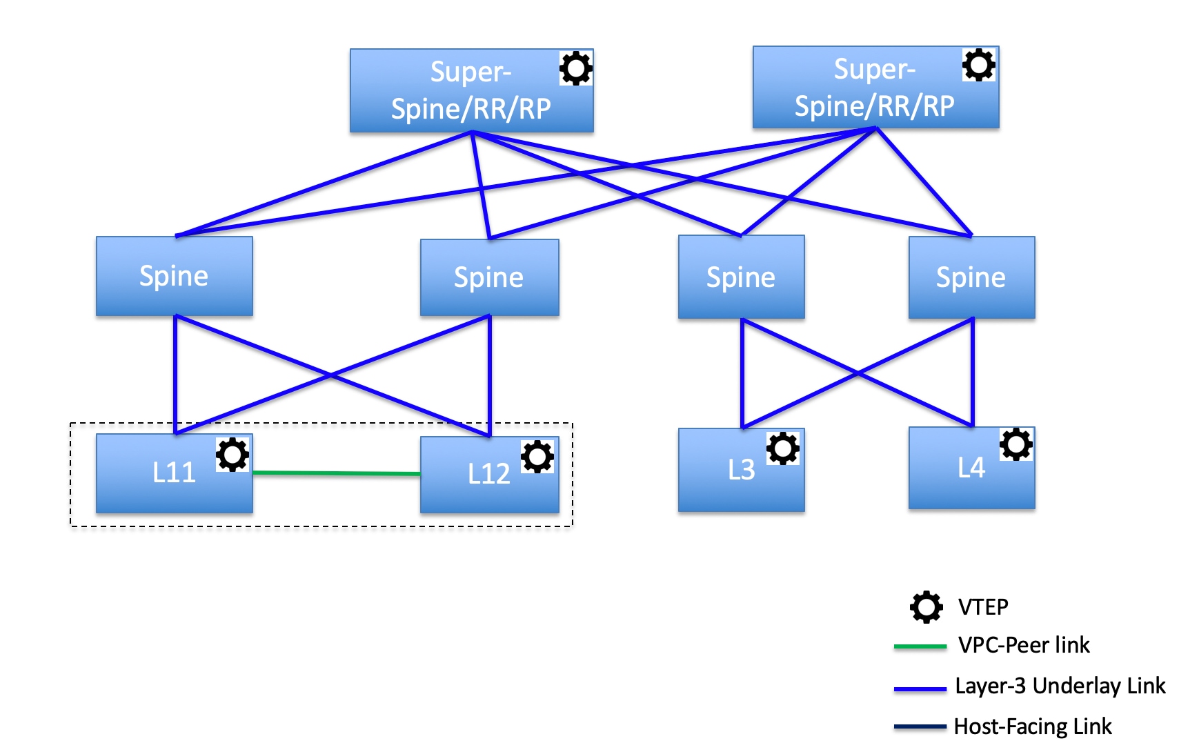
In this topology, leaf switches are connected to spines, and spines are then connected to Super Spines switches which can be super spines, border super spines, border gateway super spines.
Topology 2: Super Spine Switches Connected to Border
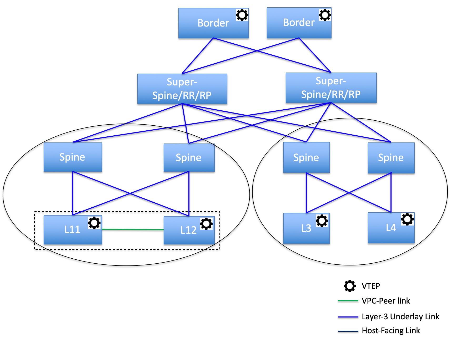
In this topology, there are four leaf switches connecting to the Spine switches, which are connected to the two Super Spine switches. These Super Spine switches are connected to the border or border gateway leaf switches.
Adding a Super Spine Switch to an Existing VXLAN BGP EVPN Fabric
Procedure
| Step 1 |
Navigate to Control > Fabric Builder. |
||
| Step 2 |
From the Fabric Builder window, click Add Switches in the actions panel. For more information, see Adding Switch Instances to the Fabric. |
||
| Step 3 |
Right-click an existing switch or the newly added switch, and use the Set role option to set the appropriate super spine role. 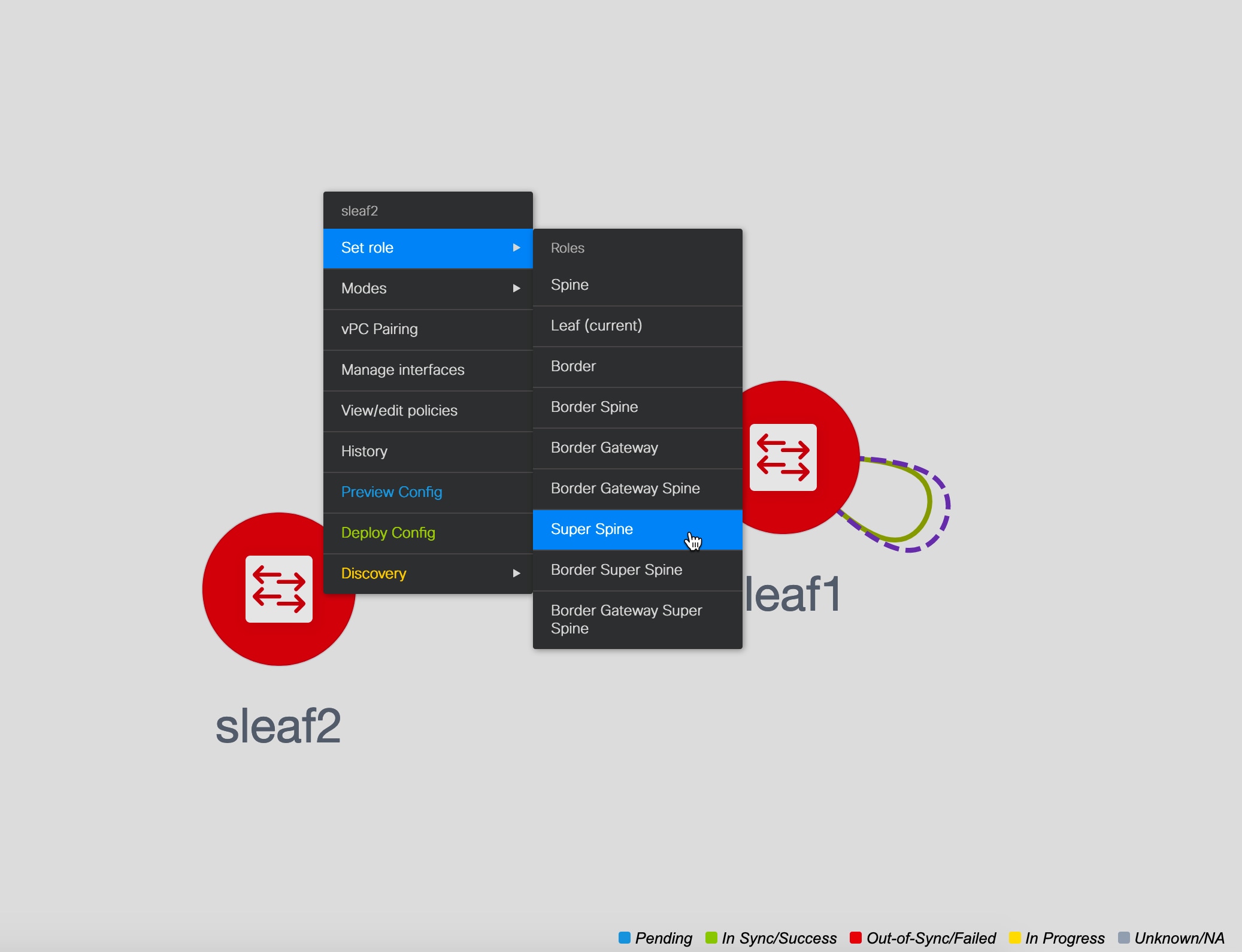
|
||
| Step 4 |
Click Save & Deploy. An error is displayed saying: Adding new switch with Super Spine role is not allowed, if save&deploy has already been performed in the fabric without any super spine role switch. |
||
| Step 5 |
Click the error, and click the Resolve button.  A confirmation dialog box is displayed asking whether you want to continue. If you click Yes, the following actions are performed by DCNM:
|
Changing the TCAM Configuration on a Device
If you are onboarding the Cisco Nexus 9300 Series switches and Cisco Nexus 9500 Series switches with X9500 line cards using the bootstrap feature with POAP, DCNM pushes the following policies depending on the switch models:
-
Cisco Nexus 9300 Series Switches: tcam_pre_config_9300 and tcam_pre_config_vxlan
-
Cisco Nexus 9500 Series Switches: tcam_pre_config_9500 and tcam_pre_config_vxlan
Perform the following steps to change the TCAM carving of a device in DCNM.
-
Choose Control > Fabrics > Fabric Builder.
-
Click the fabric containing the specified switches that have been onboarded using the bootstrap feature.
-
Click Tabular View under the Actions menu in the Fabric Builder window.
-
Select all the specified switches and click the View/Edit Policies icon.
-
Search for tcam_pre_config policies.
-
If the TCAM config is incorrect or not applicable, select all these policies and click the Delete icon to delete policies.
-
Add one or multiple tcam_config policies and provide the correct TCAM configuration. For more information about how to add a policy, see Adding PTIs for Multiple Switches.
-
Reload the respective switches.
If the switch is used as a leaf, border leaf, border gateway leaf, border spine, or border gateway spine, add the tcam_config policy with the following command and deploy.
hardware access-list tcam region racl 1024
This config is required on the switches so that the NGOAM and VXLAN Suppress ARP features are functional.
Make sure that the priority of this tcam_config policy is higher than the tcam_pre_config_vxlan policy so that the config policy with racl 1024 is configured before the tcam_pre_config_vxlan policy.
Note |
The tcam_pre_config_vxlan policy contains the config: hardware access-list tcam region arp-ether 256 double-wide. |
IPv6 Underlay Support for Easy Fabric
From Cisco DCNM Release 11.3(1), you can create a Easy fabric with IPv6 only underlay. The IPv6 underlay is supported only for the Easy_Fabric_11_1 template. In the IPv6 underlay fabric, intra-fabric links, routing loopback, vPC peer link SVI, and NVE loopback interface for VTEP are configured with IPv6 addresses. EVPN BGP neighbor peering is also established using IPv6 addressing.
The following guidelines are applicable for IPv6 underlay:
-
IPv6 underlay is supported for the Cisco Nexus 9000 Series switches with Cisco NX-OS Release 9.3(1) or higher.
-
VXLANv6 is only supported Cisco Nexus 9332C, Cisco Nexus C9364C, and Cisco Nexus modules that end with EX, FX, FX2, FX3, or FXP.
-
In VXLANv6, the platforms supported on spine are all Nexus 9000 Series and Nexus 3000 Series platforms.
-
The overlay routing protocol supported for the IPv6 fabric is BGP EVPN.
-
vPC with physical multichassis EtherChannel trunk (MCT) feature is supported for the IPv6 underlay network in DCNM. The vPC peer keep-alive can be loopback or management with IPv4 or IPv6 address.
-
Brownfield migration is supported for the fabrics with IPv6 underlay networks.
-
DHCPv6 is supported for the IPv6 underlay network.
-
The following features are not supported for VXLAN IPv6 underlay:
-
Multicast underlay
-
Tenant Routed Multicast (TRM)
-
ISIS, OSPF, and BGP authentication
-
VXLAN Multi-site
-
Dual stack underlay
-
vPC with Virtual MCT
-
DCI SR-MPLS or MPLS-LDP handoff
-
BFD
-
Super Spine switch roles
-
NGOAM
-
Creating a VXLAN Fabric with IPv6 Underlay
Procedure
| Step 1 |
Navigate to Control > Fabric Builder. |
| Step 2 |
In the Fabric Builder window, click Create Fabric. The Add Fabric window appears.
|
| Step 3 |
Enter the relevant values under the General tab. 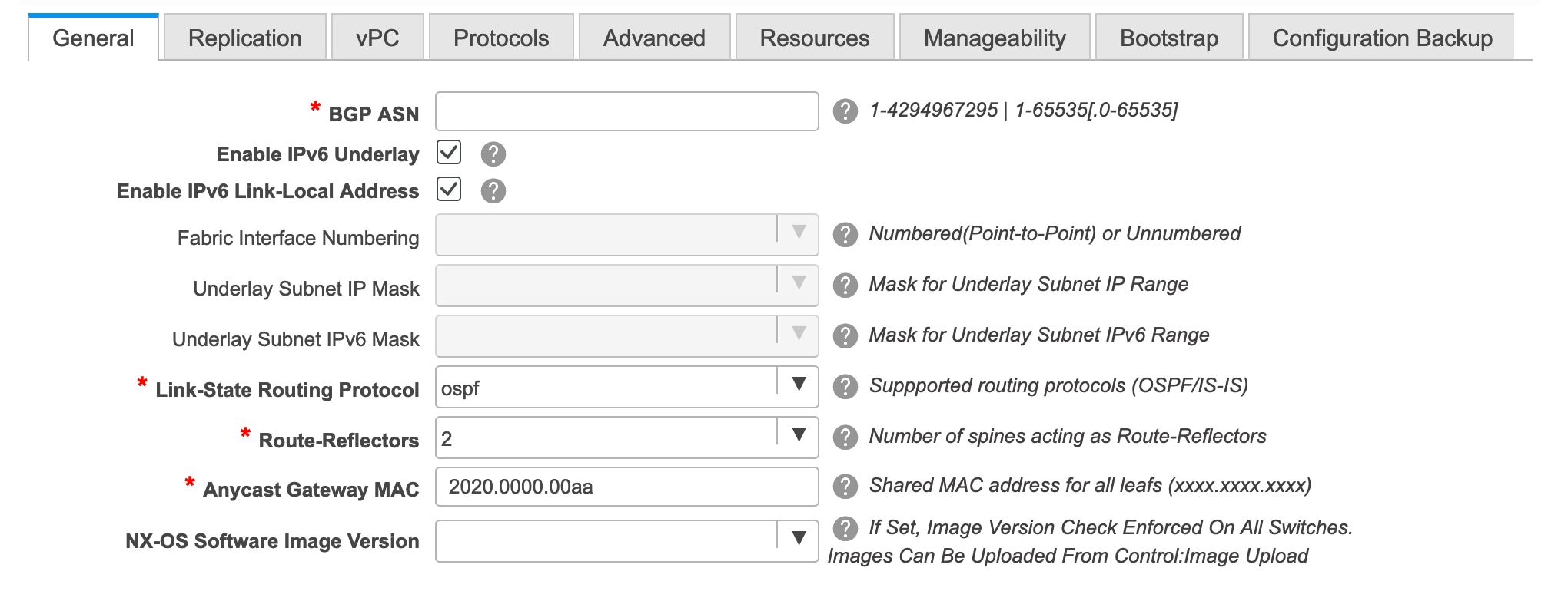 BGP ASN: Enter the BGP AS number for the fabric. You can enter either the 2 byte BGP ASN or 4 byte BGP ASN. Enable IPv6 Underlay:Select this check box to enable the IPv6 underlay feature. Enable Link-Local Address:Select this check box to use the link local addresses in the fabric between leaf-spine and spine-border interfaces. If you select this check box, the Underlay Subnet IPv6 Mask field is not editable. By default, the Enable Link-Local Address field is enabled. IPv6 underlay supports only the p2p networks. Therefore, the Fabric Interface Numbering drop-down list field is disabled. Underlay Subnet IPv6 Mask: Specifies the subnet mask for the fabric interface IPv6 addresses. Link-State Routing Protocol: The IGP used in the fabric, that is, OSPFv3 or IS-IS for VXLANv6. |
| Step 4 |
Click the Replication tab. IPv6 underlay supports only the ingress replication mode. All the fields under this tab are disabled. |
| Step 5 |
Click the vPC tab. 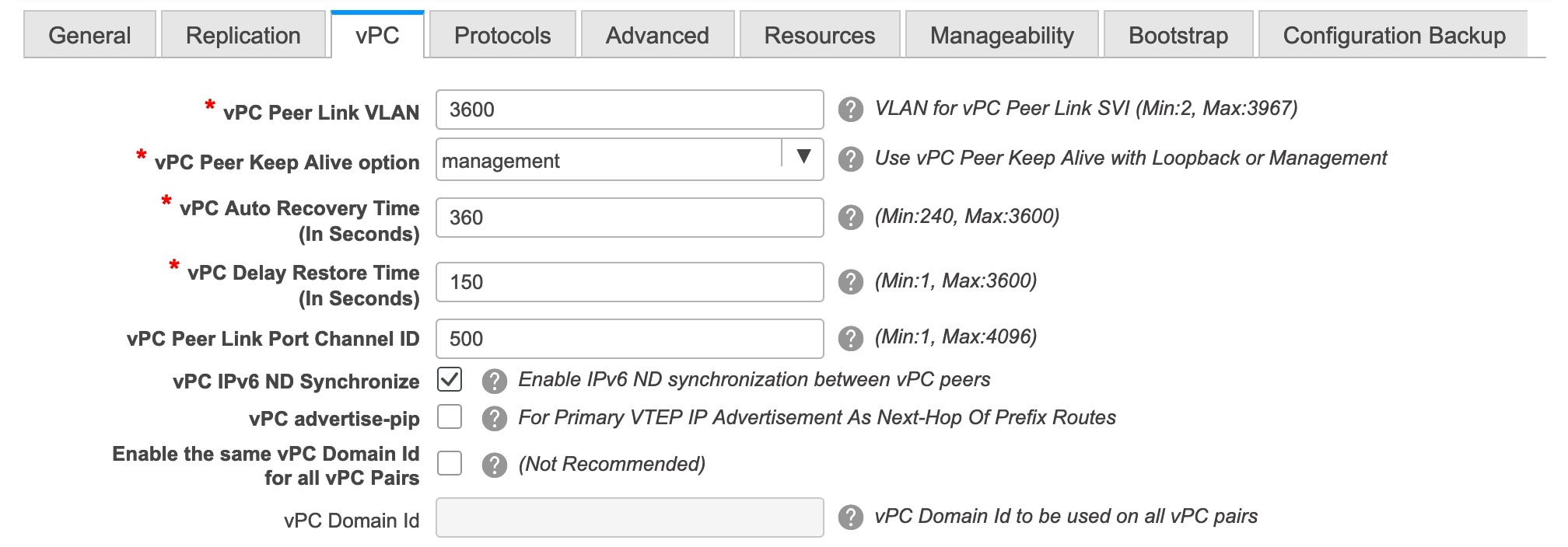 vPC Peer Keep Alive option – Choose the management or loopback option. If you want to use IP addresses assigned to the management port and the management VRF, choose management. If you use IP addresses assigned to loopback interfaces (and a non-management VRF), choose loopback. Both the options are supported for IPv6 underlay. |
| Step 6 |
Click the Protocols tab. 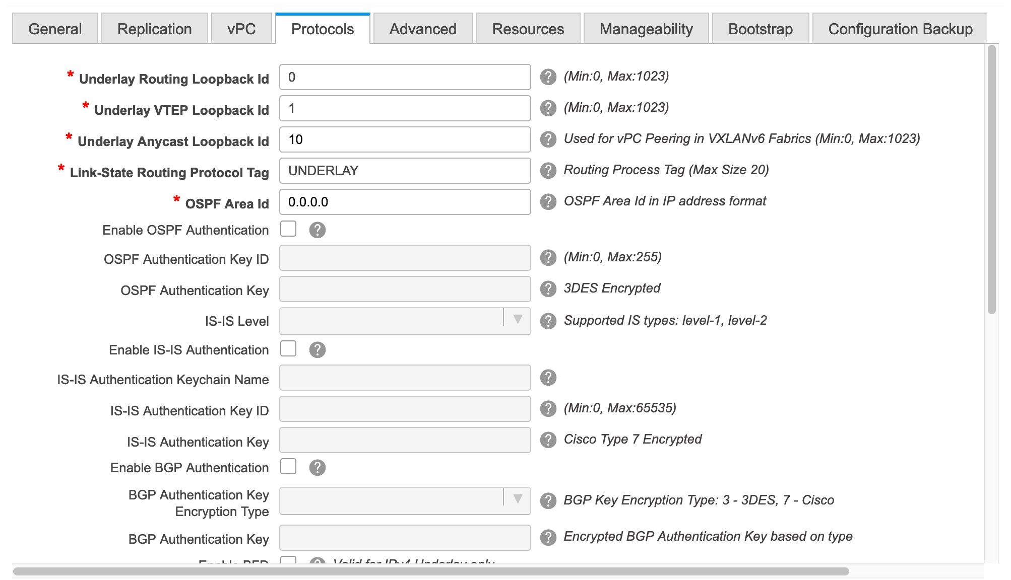 Underlay Anycast Loopback Id: Specifies the underlay anycast loopback ID for IPv6 underlay. Since an IPv6 address cannot be configured as secondary, an additional loopback interface is allocated on each vPC device. Its IPv6 address will be used as the VIP. |
| Step 7 |
Click the Resources tab. 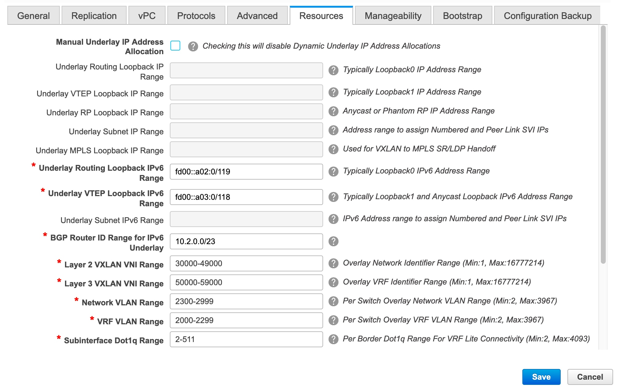 Manual Underlay IP Address Allocation: Select this check box to manually allocate underlay IP addresses. The dynamic underlay IP addresses fields are disabled. Underlay Routing Loopback IPv6 Range: Specifies loopback IPv6 addresses for the protocol peering. Underlay VTEP Loopback IPv6 Range: Specifies loopback IPv6 addresses for VTEPs. The IPv6 address for anycast will be assigned from underlay VTEP range. Underlay Subnet IPv6 Range: Specifies the IPv6 address range that is used for assigning IP addresses for numbered and peer link SVIs. To edit this field, you need to unselect the Enable Link-Local Address check box under the General tab. Underlay BGP Router ID Range: Specifies the address range to assign the BGP Router IDs. |
| Step 8 |
Click the Bootstrap tab. 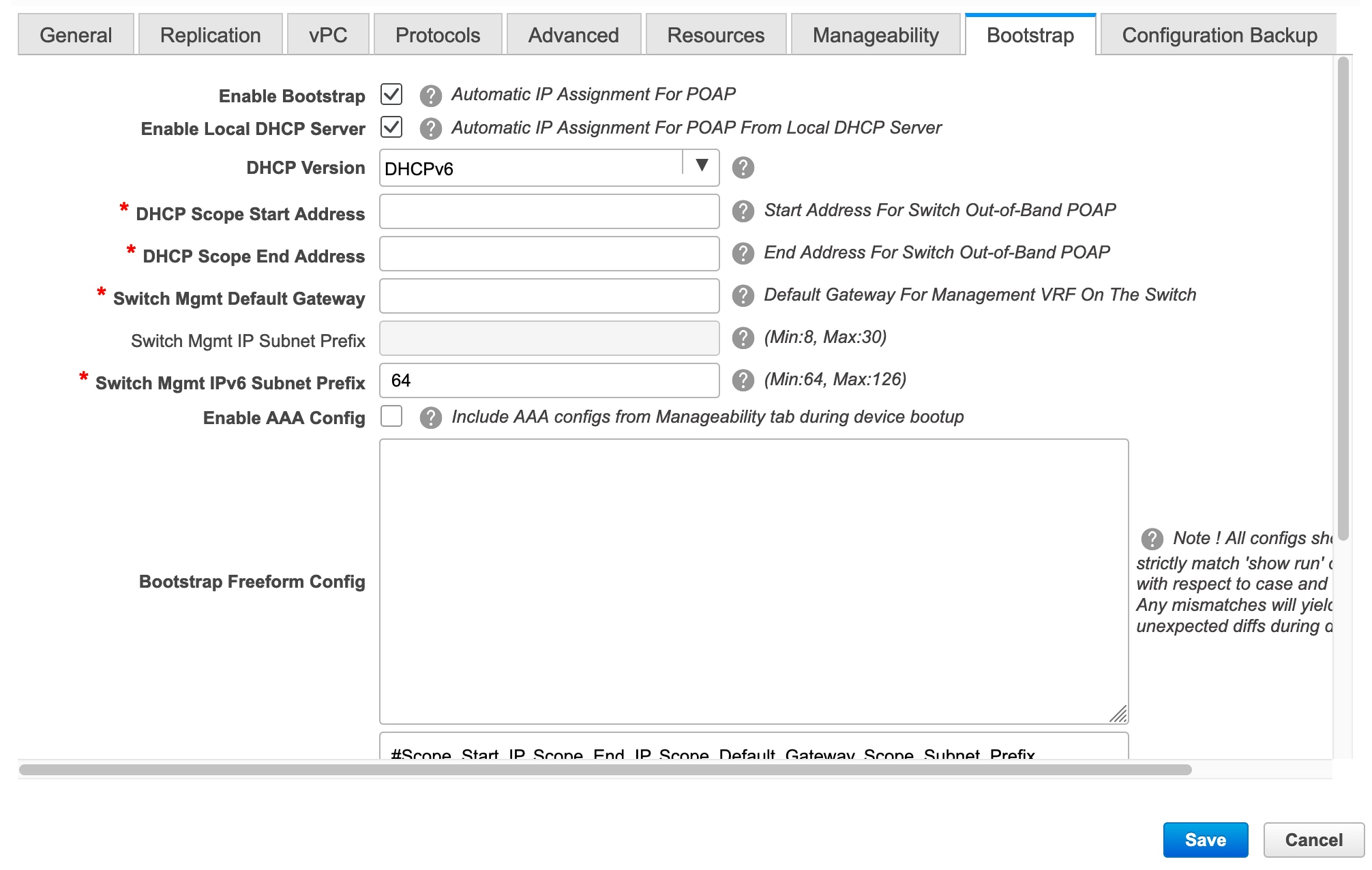 DHCP Version – Select DHCPv4 or DHCPv6 from this drop-down list. When you select DHCPv4, the Switch Mgmt IPv6 Subnet Prefix field is disabled. If you select DHCPv6, the Switch Mgmt IP Subnet Prefix is disabled. Switch Mgmt IPv6 Subnet Prefix - Specifies the IPv6 prefix for the Mgmt0 interface on the switch. The prefix can be between 64 and 126. This field is editable if you enable IPv6 for DHCP. For information about the remaining tabs and fields, see Creating a New VXLAN BGP EVPN Fabric. |
What to do next
Brownfield Deployment-Transitioning VXLAN Fabric Management to DCNM
This document explains Brownfield deployments, wherein you transition your VXLAN BGP EVPN fabric management to DCNM. The transition involves migrating existing networks configurations to DCNM.
Typically, your fabric is created and managed through manual CLI configuration or custom automation scripts. Now, you want to start managing the fabric through DCNM. After the migration, the fabric underlay and overlay networks will be managed by DCNM.
The migration procedure only supports VXLAN BGP EVPN networks that use the best practices mentioned in the Prerequisites section.
Support of simplified CLIs for VXLAN EVPN fabrics is not supported in either Greenfield or brownfield deployments.
Note |
The Brownfield deployment section is applicable for the Easy_Fabric_11_1 template. |
Prerequisites
-
DCNM-supported NX-OS software versions. For details, refer Cisco DCNM Release Notes, Release 11.3(1).
-
Underlay routing protocol is OSPF or IS-IS.
-
The supported underlay is based on the DCNM 10.2(1) POAP template's best practices for the VXLAN fabric (dcnm_ip_vxlan_fabric_templates.10.2.1.ST.1.zip) available on Cisco.com.
-
The following fabric-wide loopback interface IDs must not overlap:
-
Routing loopback interface for IGP/BGP.
-
VTEP loopback ID
-
Underlay rendezvous point loopback ID if ASM is used for multicast replication.
-
-
BGP configuration uses the ‘router-id’, which is the IP address of the routing loopback interface.
-
If the iBGP peer template is configured, then it must be configured on the leaf switches and route reflectors. The template name that needs to be used between leaf and route reflector should be identical.
-
The BGP route reflector and multicast rendezvous point (if applicable) functions are implemented on spine switches. Leaf switches do not support the functions.
-
Install DCNM 11.2(1) release software. Refer the Installation Guide for more details. Log in to DCNM and set the default LAN Credentials when prompted.
-
Familiarity with the DCNM 11.2(1) fabric management and monitoring features before initiating the migration process.
-
Familiarity with VXLAN BGP EVPN fabric concepts and functioning of the fabric from the DCNM perspective.
-
Fabric switch nodes are operationally stable and functional and all fabric links are up.
-
vPC switches and the peer links are up before the migration. Ensure that no configuration updates are in progress or changes pending.
-
Create an inventory list of the switches in the fabric with their IP addresses and credentials. DCNM uses this information to connect to the switches.
-
Shut down any other controller software you are using presently so that no further configuration changes are made to the VXLAN fabric. Alternatively, disconnect the network interfaces from the controller software (if any) so that no changes are allowed on the switches.
-
The switch overlay configurations must have the mandatory configurations defined in the shipping DCNM Universal Overlay profiles. Additional network or VRF overlay related configurations found on the switches are preserved in the freeform configuration associated with the network or VRF DCNM entries.
-
All the overlay network and VRF profile parameters such as VLAN name and route map name should be consistent across all devices in the fabric for the brownfield migration to be successful.
Guidelines and Limitations
-
Fabric interfaces can be numbered or unnumbered.
-
Various other interface types are supported.
-
The following features are unsupported.
-
eBGP underlay
-
Layer 3 port channel
-
Configuration profiles present in the brownfield configurations (the expectation is that the overlays should be configured through regular CLIs).
-
vPC Fabric Peering
-
-
Take a backup of the switch configurations and save them before the migration.
-
No configuration changes (unless instructed to do so in this document) must be made to the switches until the migration is completed. Else, significant network issues can occur.
-
Migration to Cisco DCNM is only supported for Cisco Nexus 9000 switches.
-
Multi-line banner configuration on the switch is preserved in the switch_freeform configuration, along with other configurations captured in the switch_freeform configuration, if any.
-
From DCNM Release 11.2(1), the Border Spine and Border Gateway Spine roles are supported for the brownfield migration.
-
Fabrics with IS-IS Level-1 and Level-2 are supported for the Brownfield migration.
-
Switches with the Cisco NX-OS Release 7.0(3)I4(8b) and 7.0(4)I4(x) images support the Brownfield migration. For information about feature compatibility, refer your respective platform documentation and for information about the supported software images, see Compatibility Matrix for Cisco DCNM.
Note the following guidelines and limitations:
-
The VLAN name for the network or VRF is not captured in the overlay profile if at least one of the non-spine switches have the Cisco NX-OS Release 7.0(3)I4(8b) and 7.0(4)I4(x) images. The VLAN name is captured in the freeform config associated with the overlay network or VRF. The VLAN name can be changed by updating the freeform config. For more information, see Modifying VLAN Names in a Switch with Cisco NX-OS Release 7.0(3)I4(8b) and 7.0(4)I4(x) Images.
-
Config compliance difference for TCAM CLIs on Cisco Nexus 9300 Series switches and Cisco Nexus 9500 Series switches with X9500 line cards. For more information, see Resolving Config Compliance Error on Switches with Cisco NX-OS Release 7.0(3)I4(8b) and 7.0(4)I4(x) Images.
-
The overlay profile refresh feature is unsupported for the brownfield migration of switches with the Cisco NX-OS Release 7.0(3)I4(8b) and 7.0(4)I4(x) images.
-
-
Cisco Nexus 9500 Series Switches are supported as VTEPs with border spine, BGW spine, or leaf roles for Cisco NX-OS Release 7.0.3.I7(3) or later.
-
During the brownfield migration in the Cisco DCNM Release 11.1(1), the overlay configuration profiles are deployed to switches and all the overlay related configurations are captured in the respective network or VRF freeform configs. Post migration, switches have both the original configuration CLIs and the config-profiles.
From Cisco DCNM Release 11.2(1), during the brownfield migration, the overlay config-profiles are deployed to the switches, and the original configuration CLIs are removed. Post migration, the switches only have the configuration profiles and any extra configuration that is not part of the configuration profile if the switches in the brownfield migration have the following Cisco NX-OS images:
-
Cisco NX-OS Release 7.0(3)I7(6) or newer
-
Cisco NX-OS Release 9.2(3) or newer
If the switches do not meet these requirements, the brownfield migration behavior is the same as described for the Cisco DCNM Release 11.1(1).
-
Procedure
Transitioning VXLAN fabric management to DCNM involves these steps.
-
Creating a new VXLAN BGP EVPN fabric in DCNM – This step creates a VXLAN fabric outline.
-
Initiating VXLAN fabric management transition to DCNM – This step adds switch instances to DCNM and initiates the transition.
Creating a New VXLAN BGP EVPN Fabric
First, guidelines for updating the settings are noted. Then each VXLAN fabric settings tab is explained:
-
Some values (BGP AS Number, OSPF, etc) are considered as reference points to your existing fabric, and the values you enter must match the existing fabric values.
-
For some fields (such as IP address range, VXLAN ID range), the values that are auto-populated or entered in the settings are only used for future allocation. The existing fabric values are honored during migration.
-
Some fields relate to new functions that may not exist in your existing fabric (such as advertise-pip). Enable or disable it as per your need.
-
At a later point in time, after the fabric transition is complete, you can update settings if needed.
-
Choose Control > Fabric Builder.
The Fabric Builder screen appears. When you log in for the first time, the Fabrics section has no entries. After you create a fabric, it is displayed on the Fabric Builder screen, wherein a rectangular box represents each fabric.
A standalone or member fabric contains Switch_Fabric (in the Type field), the AS number (in the ASN field), and mode of replication (in the Replication Mode field).
-
Click Create Fabric. The Add Fabric screen appears. The fields are explained:
Fabric Name - Enter the name of the fabric.
Fabric Template - From the drop-down menu, choose the Easy_Fabric_11_1 fabric template. The fabric settings for creating a standalone fabric comes up.
The tabs and their fields in the screen are explained in the subsequent points. The overlay and underlay network parameters are included in these tabs.
Note
If you are creating a standalone fabric as a potential member fabric of an MSD fabric (used for provisioning overlay networks for fabrics that are connected through EVPN Multi-Site technology), then browse through the Multi-Site Domain for VXLAN BGP EVPN Fabrics topic before member fabric creation.
-
The General tab is displayed by default. The fields in this tab are:
BGP ASN: Enter the BGP AS number the fabric is associated with.
For information about IPv6 underlay, see IPv6 Underlay Support for Easy Fabric.
Fabric Interface Numbering: Specify whether you are using a point-to-point (p2p) or unnumbered network in your existing setup.
Underlay Subnet IP Mask - Specify the subnet mask you are using for the fabric underlay IP address subnets in your existing setup.
Link-State Routing Protocol: The IGP used in the existing fabric, OSPF, or IS-IS.
Route-Reflectors – The Route Reflector count is only applicable post-migration. The existing route reflector configuration is honored when importing into the DCNM setup.
The number of spine switches that are used as route reflectors for transporting BGP traffic. Choose 2 or 4 from the drop-down box. The default value is 2.
To deploy spine devices as route reflectors, DCNM sorts the spine devices based on their serial numbers, and designates two or four spine devices as route reflectors. If you add more spine devices, existing route reflector configuration will not change.
Increasing the count - You can increase the route reflectors from two to four at any point in time. Configurations are automatically generated on the other 2 spine devices designated as route reflectors.
Decreasing the count
When you reduce four route reflectors to two, you must remove the unneeded route reflector devices from the fabric. Follow these steps to reduce the count from 4 to 2.
-
Change the value in the drop-down box to 2.
-
Identify the spine switches designated as route reflectors.
An instance of the rr_state policy is applied on the spine switch if it is a route reflector. To find out if the policy is applied on the switch, right-click the switch, and choose View/edit policies. In the View/Edit Policies screen, search rr_state in the Template field. It is displayed on the screen.
-
Delete the unneeded spine devices from the fabric (right-click the spine switch icon and choose Discovery > Remove from fabric).
If you delete existing route reflector devices, the next available spine switch is selected as the replacement route reflector.
-
Click Save and Deploy at the top right part of the fabric topology screen.
Anycast Gateway MAC: Enter the Anycast gateway MAC address of the existing fabric.
NX-OS Software Image Version: Leave this field blank. You can update this post-transition, as desired.
-
-
Click the Replication tab. Most of the fields are auto generated.
Replication Mode: The mode of replication that is used in the existing fabric, Ingress Replication, or Multicast.
When you choose Ingress replication, the multicast replication fields get disabled.
Multicast Group Subnet - The IP address prefix for multicast communication is used for post-migration allocation. The IP address prefix used in your existing fabric is honored during the transition.
A unique IP address is allocated from this group for each overlay network.
Enable Tenant Routed Multicast – Select the check box to enable Tenant Routed Multicast (TRM) as the fabric overlay multicast protocol.
If you enable TRM, the Multicast address for TRM must be entered. All the TRM specific tenant configuration is captured in the switch freeform policy linked to the tenant network and VRF profile.
Note that the TRM feature is unsupported on switches with the Cisco NX-OS Release 7.0(3)I4(8b) and 7.0(4)I4(x) images.
Default MDT address for TRM VRFs – Enter the default multicast distribution tree (MDT) IPv4 address for TRM VRFs.
Rendezvous-Points - Enter the number of spine switches acting as rendezvous points.
RP mode – Select asm (Any-Source Multicast) or bidir (Bidirectional PIM) mode.
When you choose ASM, the BiDir related fields are not enabled.
The asm RP mode supports up to 4 RPs.
The bidir mode supports up to 2 RPs. An error message is displayed if the BIDIR configuration indicates that more than 2 RPs are used.
After brownfield migration, only 2 RPs are supported in the migrated fabric. An error message is displayed when you click Save & Deploy after changing the RP count to 4.
If an RP is down or deleted from the fabric, this RP cannot be replaced by another spine as Easy Fabric does not remember the configuration of a removed switch. Easy Fabric uses a specific scheme to generate RP configuration for Bidir. Therefore, the generated Bidir configuration will not work with the brownfield imported configuration. After brownfield migration, if you change the RP count or add new spine or leaf switches, you should manually configure the PIM-Bidir feature. If a manual configuration is required, a warning message is displayed after you click Save & Deploy. For more information, see Manually Adding PIM-BIDIR Configuration for Leaf or Spine Post Brownfield Migration.
You can also modify a brownfield imported bidir configuration to use the configuration generated by Fabric Builder. For more information, see Changing a Brownfield Imported BIDIR Configuration.
Underlay RP Loopback ID – The loopback ID has to match your existing setup's loopback ID. This is the loopback ID used for the rendezvous point (RP), for multicast protocol peering purposes in the fabric underlay.
The next two fields are enabled if you choose BIDIR-PIM as the multicast mode of replication.
Underlay Primary RP Loopback ID – The primary loopback ID used for the phantom RP, for multicast protocol peering purposes in the fabric underlay.
Underlay Backup RP Loopback ID – The secondary loopback ID used for the phantom RP, for multicast protocol peering purposes in the fabric underlay.
The next two fields are enabled if Rendezvous-Points is set to 4. However, the fabric can have only 2 RPs for the brownfield migration.
Underlay Second Backup RP Loopback Id – The second fallback loopback ID for Phantom RP, for multicast protocol peering purposes in the fabric underlay.
Underlay Third Backup RP Loopback Id – The third fallback loopback ID for Phantom RP, for multicast protocol peering purposes in the fabric underlay.
-
Click the vPC tab. Most of the fields are auto generated.
vPC Peer Link VLAN - Enter the VLAN ID used for the vPC peer link SVI in the existing fabric.
vPC Peer Keep Alive option – Choose the management or loopback option, as used in the existing fabric. If you want to use IP addresses assigned to the management port and the management VRF, choose management. If you use IP addresses assigned to loopback interfaces (and a non-management VRF), choose loopback.
If you only use IPv6 addresses on the management interface, you must use the loopback option.
During the transition, the switch configuration is not checked for the following fields in the vPC tab. The switch configurations will get updated if they are different.
vPC Auto Recovery Time - Specify the vPC auto recovery time-out period in seconds, as needed.
vPC Delay Restore Time - Specify the vPC delay restore period in seconds, as needed.
vPC Peer Link Port Channel ID - Specifies the Port Channel ID for a vPC Peer Link. By default, the value in this field is 500. Change the value based on your existing settings.
vPC IPv6 ND Synchronize – Enables IPv6 Neighbor Discovery synchronization between vPC switches. The check box is enabled by default. Clear the check box to disable the function as needed.
vPC advertise-pip - Select the check box to enable the Advertise PIP feature.
Note that the Advertise PIP feature is unsupported on switches with the Cisco NX-OS Release 7.0(3)I4(8b) and 7.0(4)I4(x) images.
Enable the same vPC Domain Id for all vPC Pairs: Enable the same vPC Domain ID for all vPC pairs. When you select this field, the vPC Domain Id field is editable.
vPC Domain Id - Specifies the vPC domain ID to be used on all vPC pairs.
-
Click the Protocols tab. Most of the fields are auto generated. You can update the fields if needed.
Underlay Routing Loopback Id - The loopback interface ID is populated as 0 since loopback0 is usually used for fabric underlay IGP peering purposes. This must match the existing configuration on the switches. This must be the same across all the switches.
Underlay VTEP Loopback Id - The loopback interface ID is populated as 1 since loopback1 is usually used for the VTEP peering purposes. This must match the existing configuration on the switches. This must be the same across all the switches where VTEPs are present.
Link-State Routing Protocol Tag - Enter the existing fabric’s routing protocol tag in this field to define the type of network.
OSPF Area ID – The OSPF area ID of the existing fabric, if OSPF is used as the IGP within the fabric.
Note
The OSPF or IS-IS authentication fields are enabled based on your selection in the Link-State Routing Protocol field in the General tab.
Enable OSPF Authentication – Select the check box to enable the OSPF authentication. Deselect the check box to disable it. If you enable this field, the OSPF Authentication Key ID and OSPF Authentication Key fields are enabled.
OSPF Authentication Key ID – Enter the OSPF authentication key ID.
OSPF Authentication Key - The OSPF authentication key must be the 3DES key from the switch.
Note
Plain text passwords are not supported. Login to the switch, retrieve the OSPF authentication details.
You can obtain the OSPF authentication details by using the show run ospf command on your switch.
# show run ospf | grep message-digest-key
ip ospf message-digest-key 127 md5 3 c7c83ec78f38f32f3d477519630faf7b
In this example, the OSPF authentication key ID is 127 and the authentication key is c7c83ec78f38f32f3d477519630faf7b.
For information about how to configure a new key and retrieve it, see Retrieving the 3DES Encrypted OSPF Authentication Key.
IS-IS Level - Select the IS-IS level from this drop-down list.
Enable IS-IS Authentication - Select the check box to enable IS-IS authentication. Deselect the check box to disable it. If you enable this field, the IS-IS authentication fields are enabled.
IS-IS Authentication Keychain Name - Enter the keychain name.
IS-IS Authentication Key ID - Enter the IS-IS authentication key ID.
IS-IS Authentication Key - Enter the Cisco Type 7 encrypted key.
Note
Plain text passwords are not supported. Login to the switch, retrieve the IS-IS authentication details.
You can obtain the IS-IS authentication details by using the show run | section “key chain” command on your switch.
# show run | section “key chain”
key chain CiscoIsisAuth
  key 127
      key-string 7 075e731f
In this example, the keychain name is CiscoIsisAuth, the key ID is 127, and the type 7 authentication key is 075e731f.
Enable BGP Authentication - Select the check box to enable BGP authentication. Deselect the check box to disable it. If you enable this field, the BGP Authentication Key Encryption Type and BGP Authentication Key fields are enabled.
BGP Authentication Key Encryption Type – Choose the 3 for 3DES encryption type, and 7 for Cisco encryption type.
BGP Authentication Key - Enter the encrypted key based on the encryption type.
Note
Plain text passwords are not supported. Login to the switch, retrieve the BGP authentication details.
You can obtain the BGP authentication details by using the show run bgp command on your switch.
# show run bgp
neighbor 10.2.0.2
remote-as 65000
password 3 sd8478fswerdfw3434fsw4f4w34sdsd8478fswerdfw3434fsw4f4w3
In this example, the BGP authentication key is displayed after the encryption type 3.
Enable BFD feature – Select the check box to enable the BFD feature.
The BFD feature is disabled by default.
Make sure that the BFD feature setting matches with the switch configuration. If the switch configuration contains feature bfd but the BFD feature is not enabled in the fabric settings, config compliance generates diff to remove the BFD feature after brownfield migration. That is, no feature bfd is generated after migration.
From Cisco DCNM Release 11.3(1), BFD within a fabric is supported natively. The BFD feature is disabled by default in the Fabric Settings. If enabled, BFD is enabled for the underlay protocols with the default settings. Any custom required BFD configurations must be deployed via the per switch freeform or per interface freeform policies.
The following config is pushed after you select the Enable BFD check box:
feature bfdFor information about BFD feature compatibility, refer your respective platform documentation and for information about the supported software images, see Compatibility Matrix for Cisco DCNM.
Enable BFD for iBGP: Select the check box to enable BFD for the iBGP neighbor. This option is disabled by default.
Enable BFD for OSPF: Select the check box to enable BFD for the OSPF underlay instance. This option is disabled by default, and it is grayed out if the link state protocol is ISIS.
Enable BFD for ISIS: Select the check box to enable BFD for the ISIS underlay instance. This option is disabled by default, and it is grayed out if the link state protocol is OSPF.
Enable BFD for PIM: Select the check box to enable BFD for PIM. This option is disabled by default, and it is be grayed out if the replication mode is Ingress.
Here are the examples of the BFD global policies:
router ospf <ospf tag>
   bfd

router isis <isis tag>
  address-family ipv4 unicast
    bfd

ip pim bfd

router bgp <bgp asn>
  neighbor <neighbor ip>
    bfd
Enable BFD Authentication: Select the check box to enable BFD authentication. If you enable this field, the BFD Authentication Key ID and BFD Authentication Key fields are editable.
Note
-
BFD Authentication is not supported when the Fabric Interface Numbering field under the General tab is set to unnumbered. The BFD authentication fields will be grayed out automatically.
-
After you upgrade from DCNM Release 11.2(1) with BFD enabled to DCNM Release 11.3(1), the following configs are pushed to the switch:
no ip redirects
no ipv6 redirects
BFD Authentication Key ID: Specifies the BFD authentication key ID for the interface authentication. The default value is 100.
BFD Authentication Key: Specifies the BFD authentication key.
For information about how to retrieve the BFD authentication parameters, see Retrieving the Encrypted BFD Authentication Key.
iBGP Peer-Template Config – Add iBGP peer template configurations on the leaf switches and route reflectors to establish an iBGP session between the leaf switch and route reflector. Set this field based on switch configuration. If this field is blank, it implies that the iBGP peer template is not used. If the iBGP peer template is used, enter the peer template definition as defined on the switch. The peer template name on devices configured with BGP should be the same as defined here.
Note
If you use the iBGP peer template, include the BGP authentication configuration in this template config field. Additionally, uncheck the Enable BGP Authentication check box to avoid duplicating the BGP configuration.
-
-
Click the Advanced tab. Most of the fields are auto generated.
VRF Template and VRF Extension Template: Specifies the VRF template for creating VRFs, and the VRF extension template for enabling VRF extension to other fabrics.
Network Template and Network Extension Template: Specifies the network template for creating networks, and the network extension template for extending networks to other fabrics.
You must not change the templates when migrating. Only the Universal templates are supported for overlay migration.
Site ID - The ID for this fabric if you are moving this fabric within an MSD. You can update this field post-migration.
Intra Fabric Interface MTU - Specifies the MTU for the intra fabric interface. This value should be an even number.
Layer 2 Host Interface MTU - Specifies the MTU for the layer 2 host interface. This value should be an even number.
Power Supply Mode - Choose the appropriate power supply mode.
CoPP Profile - Choose the Control Plane Policing (CoPP) profile policy used in the existing fabric. By default, the strict option is populated.
VTEP HoldDown Time - Specifies the NVE source interface hold down time.
Brownfield Overlay Network Name Format: Enter the format to be used to build the overlay network name during a brownfield import or migration. The network name should not contain any white spaces or special characters except underscore (_) and hyphen (-). The network name must not be changed once the brownfield migration has been initiated. See the Creating Networks for the Standalone Fabric section for the naming convention of the network name. The syntax is [<string> | $$VLAN_ID$$] $$VNI$$ [<string>| $$VLAN_ID$$] and the default value is Auto_Net_VNI$$VNI$$_VLAN$$VLAN_ID$$. When you create networks, the name is generated according to the syntax you specify. The following table describes the variables in the syntax.
Variables
Description
$$VNI$$
Specifies the network VNI ID found in the switch configuration. This is a mandatory keyword required to create unique network names.
$$VLAN_ID$$
Specifies the VLAN ID associated with the network.
VLAN ID is specific to switches, hence DCNM will pick the VLAN ID from one of the switches, where the network is found, randomly and use it in the name.
We recommend not to use this unless the VLAN ID is consistent across the fabric for the VNI.
<string>
This variable is optional and you can enter any number of alphanumeric characters that meet the network name guidelines.
Example overlay network name: Site_VNI12345_VLAN1234
Note
Ignore this field for greenfield deployments. The Brownfield Overlay Network Name Format applies for the following brownfield imports:
-
CLI-based overlays
-
Configuration profile-based overlay where the configuration profiles were created in Cisco DCNM Release
10.4(2).
Enable VXLAN OAM - Enables the VXLAM OAM function for existing switches.
This is enabled by default. Clear the check box to disable VXLAN OAM function.
If you want to enable the VXLAN OAM function on specific switches and disable on other switches in the fabric, you can use freeform configurations to enable OAM and disable OAM in the fabric settings.
Note
The VXLAN OAM feature in Cisco DCNM is only supported on a single fabric or site.
Note that the NGOAM feature is unsupported on switches with the Cisco NX-OS Release 7.0(3)I4(8b) and 7.0(4)I4(x) images.
Enable Tenant DHCP – Select the check box to enable the tenant DHCP support.
Note
Ensure that Enable Tenant DHCP is enabled before enabling DHCP related parameters in the overlay profiles.
Enable NX-API - Specifies enabling of NX-API.
Enable NX-API on HTTP - Specifies enabling of NX-API on HTTP.
Enable Policy-Based Routing (PBR) - Select this check box to enable routing of packets based on the specified policy.
Enable Strict Config Compliance - Enable the Strict Config Compliance feature by selecting this check box. By default, this feature is disabled.
Enable AAA IP Authorization - Enables AAA IP authorization, when IP Authorization is enabled in the AAA Server
Greenfield Cleanup Option – Enable or disable the switch cleanup option for Greenfield switches. This is applicable post-migration when new switches are added.
Enable Precision Time Protocol (PTP): Enables PTP across a fabric. When you select this check box, PTP is enabled globally and on core-facing interfaces. Additionally, the PTP Source Loopback Id and PTP Domain Id fields are editable. For more information, see Precision Time Protocol for Easy Fabric.
PTP Source Loopback Id: Specifies the loopback interface ID Loopback that is used as the Source IP Address for all PTP packets. The valid values range from 0 to 1023. The PTP loopback ID cannot be the same as RP, Phantom RP, NVE, or MPLS loopback ID. Otherwise, an error will be generated. The PTP loopback ID can be the same as BGP loopback or user-defined loopback which is created from DCNM.
If the PTP loopback ID is not found during Save & Deploy, the following error is generated:
Loopback interface to use for PTP source IP is not found. Please create PTP loopback interface on all the devices to enable PTP feature.
PTP Domain Id: Specifies the PTP domain ID on a single network. The valid values range from 0 to 127.
Enable MPLS Handoff: Select the check box to enable the MPLS Handoff feature. For more information, see Border Provisioning Use Case in VXLAN BGP EVPN Fabrics - MPLS SR and LDP Handoff.
Note: For the brownfield import, you need to select the Enable MPLS Handoff feature. Most of the IFC configuration will be captured in switch_freeform.
Underlay MPLS Loopback Id: Specifies the underlay MPLS loopback ID. The default value is 101.
Enable Default Queuing Policies: Check this check box to apply QoS policies on all the switches in this fabric. To remove the QoS policies that you applied on all the switches, uncheck this check box, update all the configurations to remove the references to the policies, and save and deploy. From Cisco DCNM Release 11.3(1), pre-defined QoS configurations are included that can be used for various Cisco Nexus 9000 Series Switches. When you check this check box, the appropriate QoS configurations are pushed to the switches in the fabric. The system queuing is updated when configurations are deployed to the switches. You can perform the interface marking with defined queuing policies, if required, by adding the required configuration to the per interface freeform block.
Review the actual queuing policies by opening the policy file in the template editor. From Cisco DCNM Web UI, choose Control > Template Library. Search for the queuing policies by the policy file name, for example, queuing_policy_default_8q_cloudscale. Choose the file and click the Modify/View template icon to edit the policy.
See the Cisco Nexus 9000 Series NX-OS Quality of Service Configuration Guide for platform specific details.
N9K Cloud Scale Platform Queuing Policy: Choose the queuing policy from the drop-down list to be applied to all Cisco Nexus 9200 Series Switches and the Cisco Nexus 9000 Series Switches that ends with EX, FX, and FX2 in the fabric. The valid values are queuing_policy_default_4q_cloudscale and queuing_policy_default_8q_cloudscale. Use the queuing_policy_default_4q_cloudscale policy for FEXes. You can change from the queuing_policy_default_4q_cloudscale policy to the queuing_policy_default_8q_cloudscale policy only when FEXes are offline.
N9K R-Series Platform Queuing Policy: Choose the queuing policy from the drop-down list to be applied to all Cisco Nexus switches that ends with R in the fabric. The valid value is queuing_policy_default_r_series.
Other N9K Platform Queuing Policy: Choose the queuing policy from the drop-down list to be applied to all other switches in the fabric other than the switches mentioned in the above two options. The valid value is queuing_policy_default_other.
Leaf Freeform Config and Spine Freeform Config - You can enter these fields after fabric transitioning is complete, as needed.
Intra-fabric Links Additional Config - You can enter this field after fabric transitioning is complete, as needed.
-
-
Click the Resources tab.
Manual Underlay IP Address Allocation – Do not select this check box if you are transitioning your VXLAN fabric management to DCNM.
Review the ranges and ensure they are consistent with the existing fabric. The migration will honor the existing resources as found on the fabric. The range settings apply to post migration allocation.
Underlay Routing Loopback IP Range - Specifies loopback IP addresses for the protocol peering.
Underlay VTEP Loopback IP Range - Specifies loopback IP addresses for VTEPs.
Underlay RP Loopback IP Range - Specifies the anycast or phantom RP IP address range.
Underlay Subnet IP Range - IP addresses for underlay P2P routing traffic between interfaces.
Layer 2 VXLAN VNI Range and Layer 3 VXLAN VNI Range - Specifies the VXLAN VNI IDs for the fabric.
Network VLAN Range and VRF VLAN Range - VLAN ranges for the Layer 3 VRF and overlay network.
Subinterface Dot1q Range - Specifies the subinterface range when L3 sub interfaces are used.
VRF Lite Deployment - Specify the VRF Lite method for extending inter fabric connections.
If you select Manual, the VRF Lite subnet details are required so that the resource manager can reserve the address space.
If you select Back2BackOnly, ToExternalOnly, or Both, then the VRF Lite subnet fields are enabled.
VRF Lite Subnet IP Range and VRF Lite Subnet Mask – These fields are populated with the DCI subnet details. Update the fields as needed.
The values shown in your screen are automatically generated. If you want to update the IP address ranges, VXLAN Layer 2/Layer 3 network ID ranges or the VRF/Network VLAN ranges, ensure the following:
Note
When you update a range of values, ensure that it does not overlap with other ranges. You should only update one range of values at a time. If you want to update more than one range of values, do it in separate instances. For example, if you want to update L2 and L3 ranges, you should do the following.
-
Update the L2 range and click Save.
-
Click the Edit Fabric option again, update the L3 range and click Save.
Service Network VLAN Range - Specifies a VLAN range in the Service Network VLAN Range field. This is a per switch overlay service network VLAN range. The minimum allowed value is 2 and the maximum allowed value is 3967.
Route Map Sequence Number Range - Specifies the route map sequence number range. The minimum allowed value is 1 and the maximum allowed value is 65534.
The remaining tabs do not require updates. However, their purpose is mentioned.
-
-
Click the Manageability tab - Enter the DNS, NTP, AAA, or syslog servers’ IP address, VRF, and other applicable information matching the switch configuration. If there are more than two servers for these features, add the configurations of the additional servers to the Leaf Freeform Config and Spine Freeform Config fields in the Advanced tab.
Note
If AAA configs are not specified in the fabric settings, switch_freeform PTI with source as UNDERLAY_AAA and description as DCNM Extra AAA Configurations will be created.
-
Click the Bootstrap tab. Update the fields in this tab post transition, when new switches are added to the fabric.
-
Click the Configuration Backup tab. Leave the fields in this tab blank. You can update post transition.
-
Click Save after filling and updating relevant information. A note appears briefly at the bottom right part of the screen, indicating that the fabric is created. When a fabric is created, the fabric page comes up. The fabric name appears at the top left part of the screen.
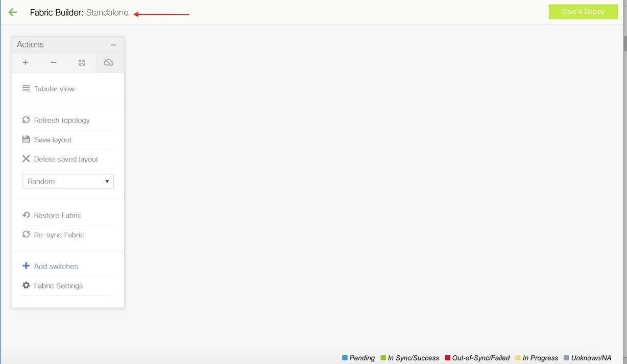
The Actions panel at the left part of the screen allows you to perform various functions. One of them is the Add switches option to add switches to the fabric. After you create a fabric, you should add fabric devices. The process is explained next:
Adding Switch Instances and Transitioning VXLAN Fabric Management to DCNM
-
In the fabric topology screen, click Add switches. The Inventory Management screen comes up. The Discover Existing Switches tab is displayed by default.
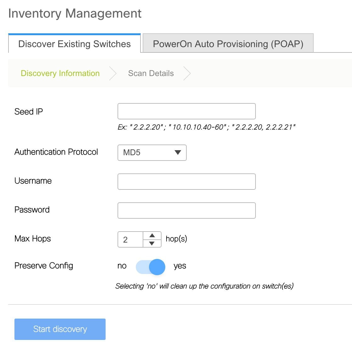
The POAP tab is only used for adding new switches to the fabric. Use the tab only after migrating your existing fabric to DCNM.
-
Enter the IP address (Seed IP), administrator username and password (Username and Password fields) of the switch, and set the Max Hops count for the switch. Ensure that all fabric switches can be added to DCNM at once.
Important - Ensure that the Preserve Config field remains set to yes. Selecting 'no' can cause significant configuration loss and fabric disruption.
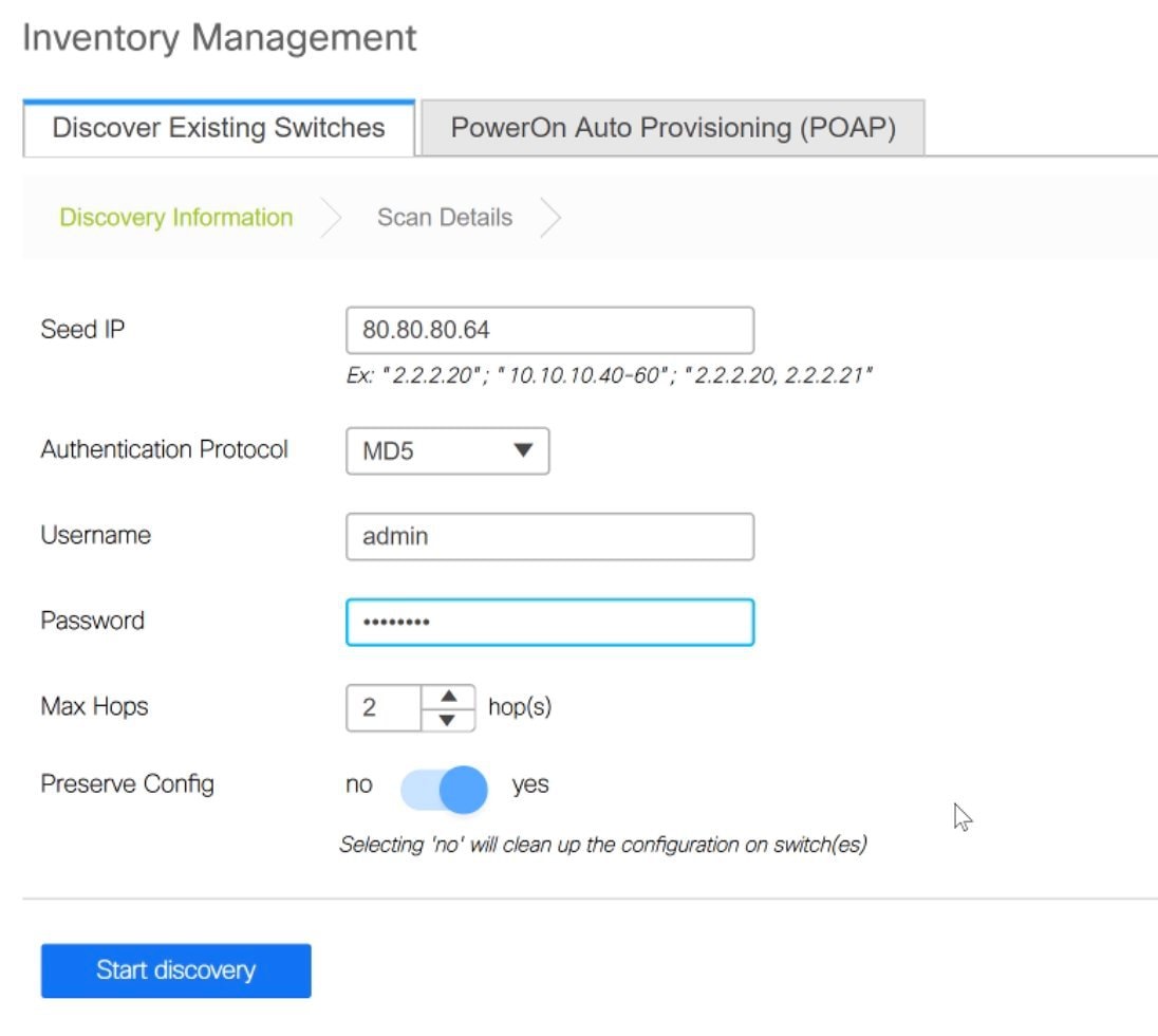
-
Click Start discovery, at the bottom part of the screen. The switch with the specified IP address and switches up to two hops away (depending on the setting of Max Hops) from it are populated in the Scan Details section.
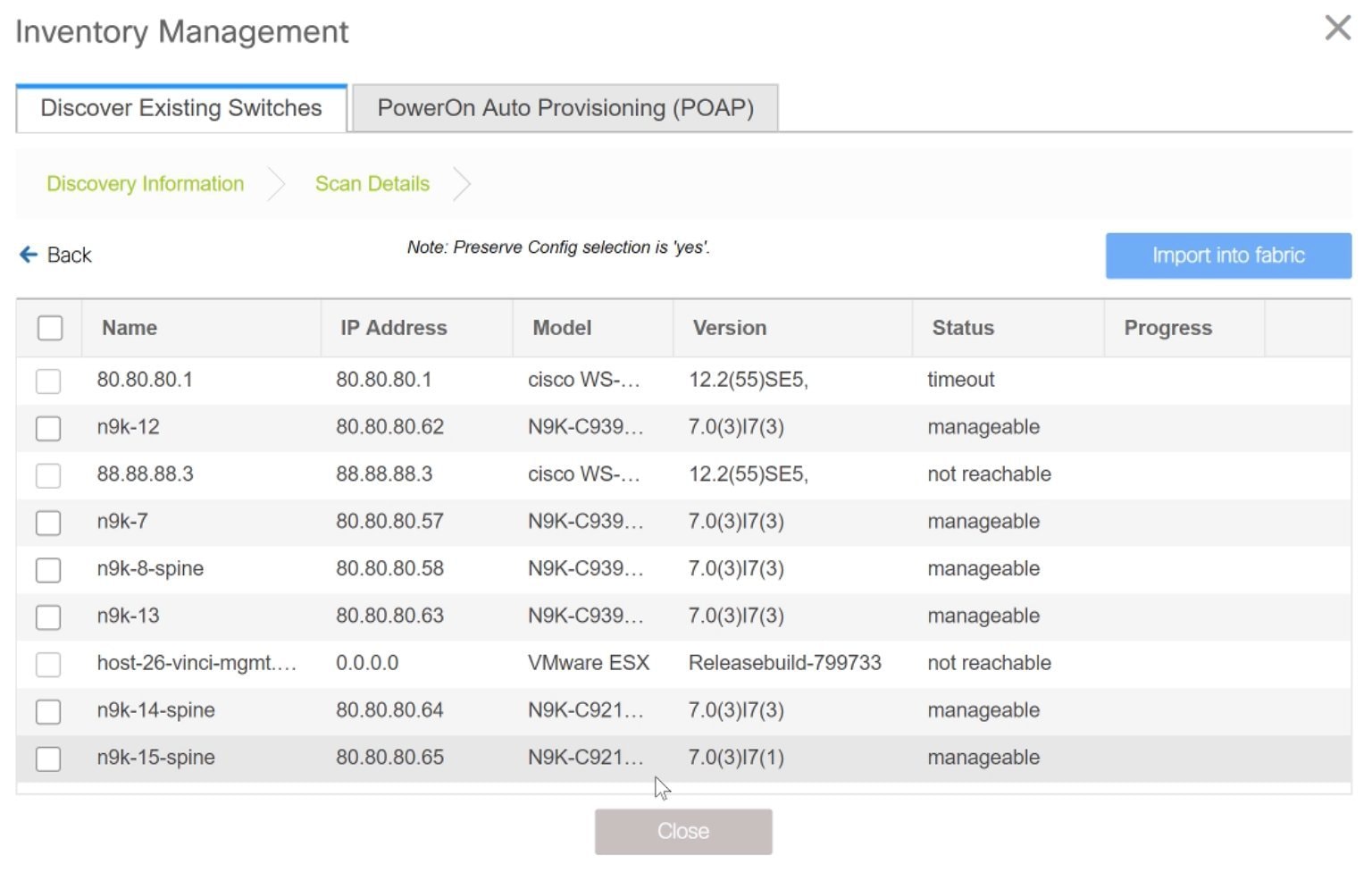
-
Select the check box next to the concerned switches and click Import into fabric.
It is a best practice to discover multiple switches at once. The switches must be properly cabled and connected to the DCNM server and the switch status must be manageable.
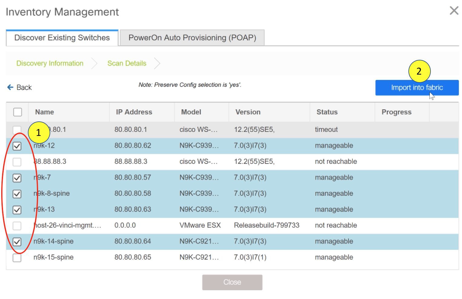
The switch discovery process is initiated. The Progress column displays progress for all the selected switches. It displays done for each switch on completion.
Note
You must not close the screen (and try to import switches again) till all selected switches are imported or an error message comes up.
If an error message comes up, close the screen. The fabric topology screen comes up. The error messages are displayed at the top right part of the screen. Resolve the errors and initiate the import process again by clicking on Add Switches in the Actions panel.
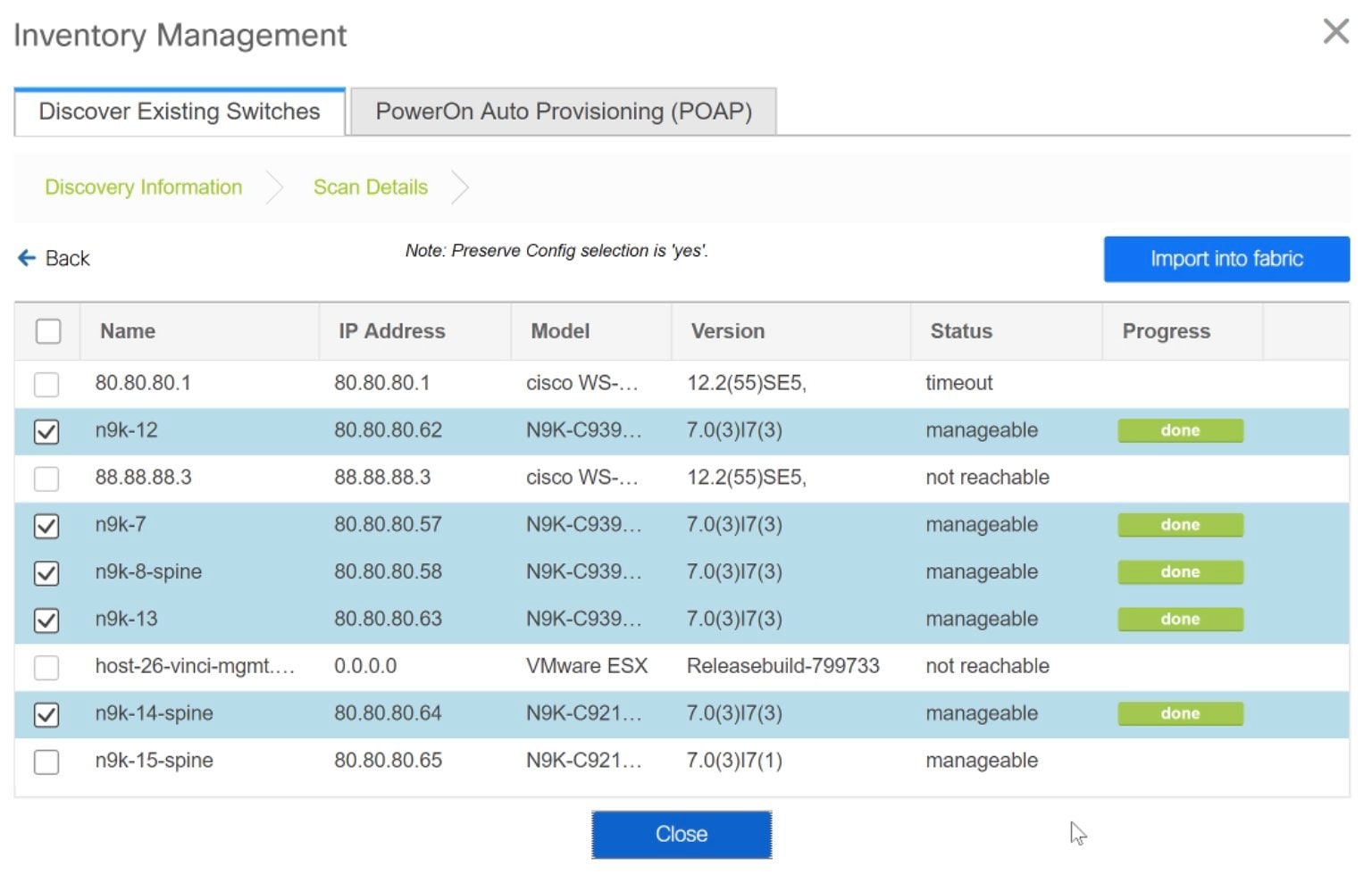
After DCNM discovers all the switches, and the Progress column displays done for all switches, close the screen. The fabric topology screen comes up again. The switch is in Migration Mode now and the Migration mode label is displayed on the switch icons.
At this point, you must not try to add Greenfield or new switches. Support is not available for adding new switches during the migration process. It might lead to undesirable consequences for your network. However, you can add a new switch after the migration process is complete.
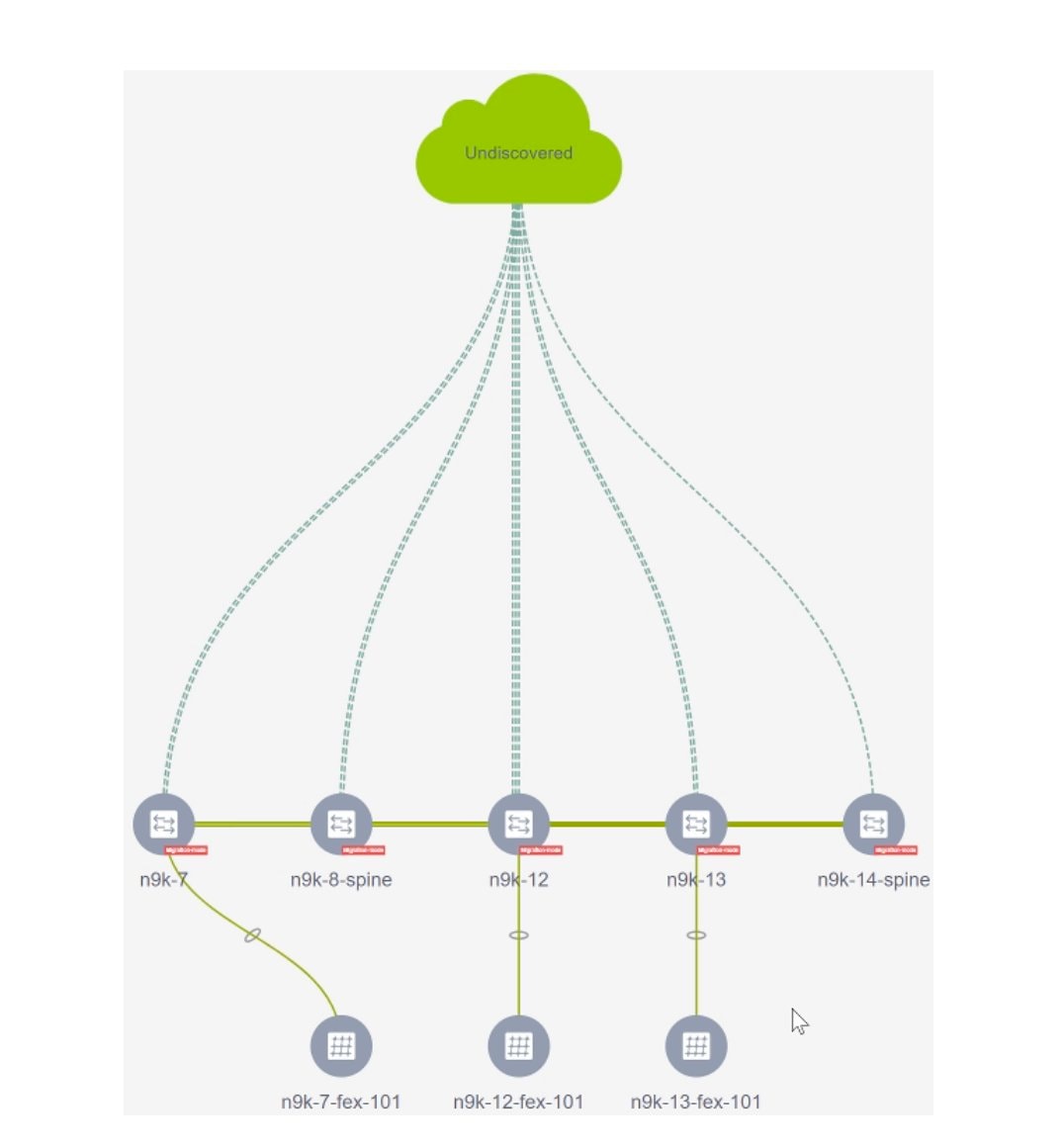
Note
The switch discovery process might fail for a few switches, and the Discovery Error message displayed. However, such switches are still displayed in the fabric topology. You must remove such switches from the fabric (Right-click the switch icon and click Discovery > Remove from fabric), and import them again.
You must not proceed to the next step till all switches in the existing fabric are discovered in DCNM.
-
Each switch’s role and vPC pairing must be set during the fabric migration process.
Right-click the switch icon and use the Set role option (Leaf, Border, etc) to update switch role.
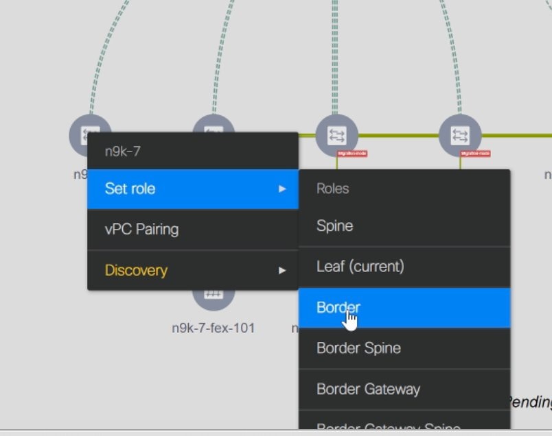
If you choose the Hierarchical layout for display (in the Actions panel), the topology automatically gets aligned as per role assignment, with the leaf switches at the bottom, the spine switches connected on top of them, and the border switches at the top.
Note
The supported roles for switches with the Cisco NX-OS Release 7.0(3)I4(8b) and 7.0(4)I4(x) images are Border Leaf, Border Spine, Leaf, and Spine
vPC Pairing - The vPC pairing must be done for switches where the Layer 3 vPC peer-keep alive is used. The vPC configuration is automatically picked up from the switches when the vPC peer keep alive is established through the management option. This pairing reflects in the GUI only after the migration is complete.
-
Right-click the switch icon and click vPC Pairing to set a vPC switch pair.
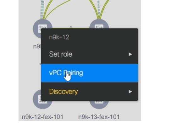
The Select vPC peer screen comes up. It lists potential vPC peer switches.
-
Select the appropriate switch and click OK. The fabric topology comes up again. The vPC pair is formed now.
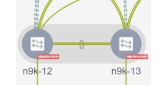
Note
Check if you have added all switches from the current fabric. If you have missed adding switches, add them now. Once you are certain that you have imported all existing switches, move to the next step, the Save and Deploy option.
-
-
Use the Save and Deploy option (at the top right part of the screen) to sync configurations between the switch and DCNM.
The Saving Fabric Configuration message comes up immediately. This indicates that overlay and underlay network migration, and switch and port channel settings migration to DCNM is initiated.
If there are configuration mismatches, error messages are displayed. Update changes in the fabric settings or the switch configuration as needed, and click Save and Deploy again.
After the migration of underlay and overlay networks, the Configuration Deployment screen comes up.
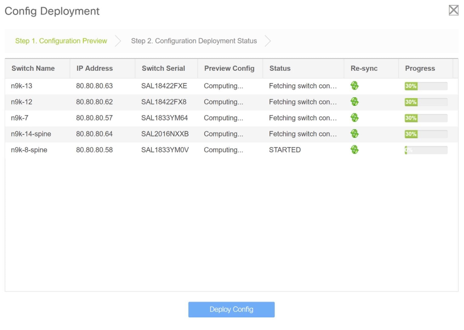
The Preview Config column is updated with entries denoting a specific number of lines.
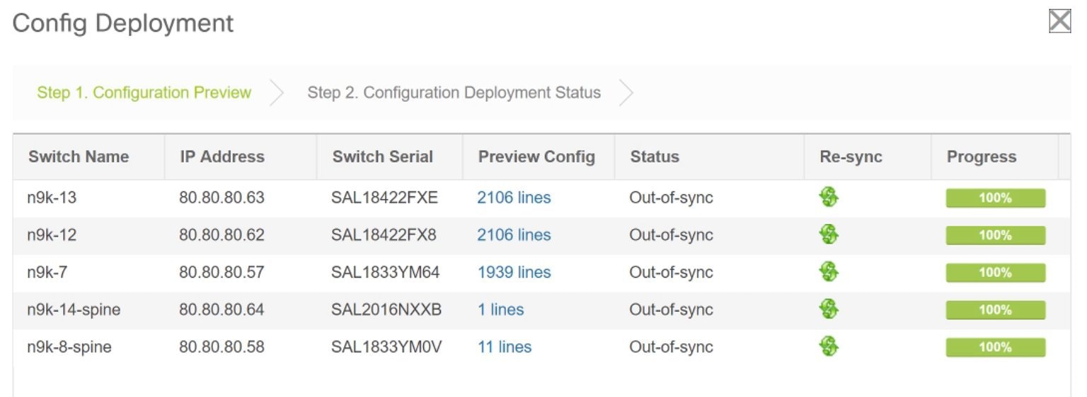
We strongly recommend that you preview the configuration before proceeding to deploy it on the switches. Click the Preview Config column entry. The Config Preview screen comes up. It lists the pending configurations on the switch.
The Side-by-side Comparison tab displays the running configuration and expected configuration side-by-side.
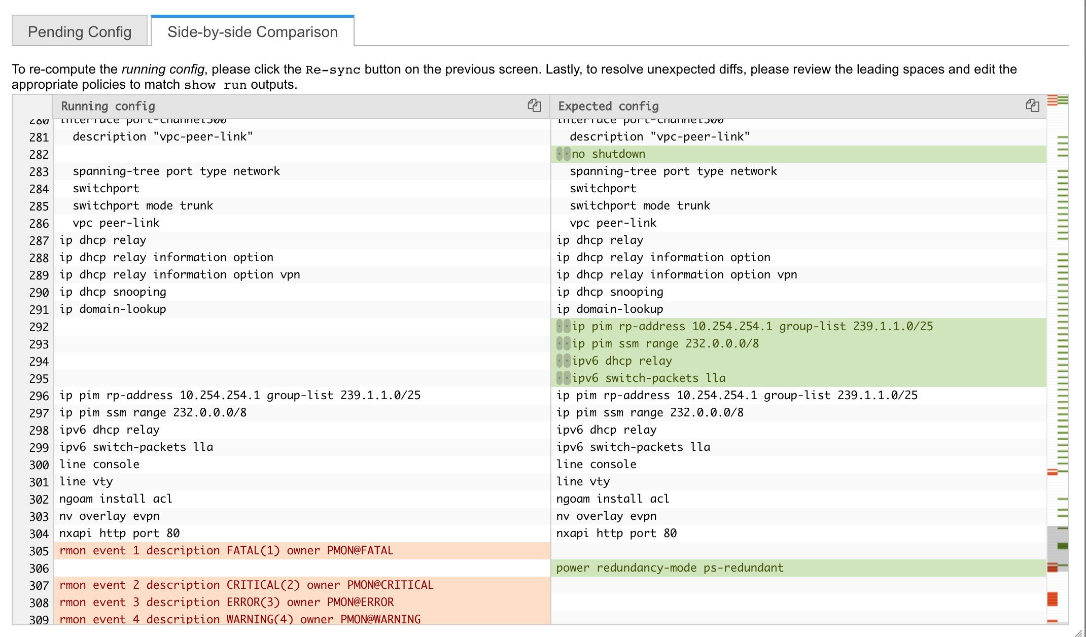
Close the preview screen.
-
Click Deploy Config at the bottom part of the screen to initiate pending configuration onto the switch. The Status column displays FAILED or SUCCESS state. For a FAILED status, investigate the reason for failure to address the issue.
The progress bar shows 100% for each switch. After correct provisioning and successful configuration compliance, close the screen. In the fabric topology screen that comes up, all imported switch instances are displayed in green color, indicating successful configuration. Also, the Migration Mode label is not displayed on any switch icon.
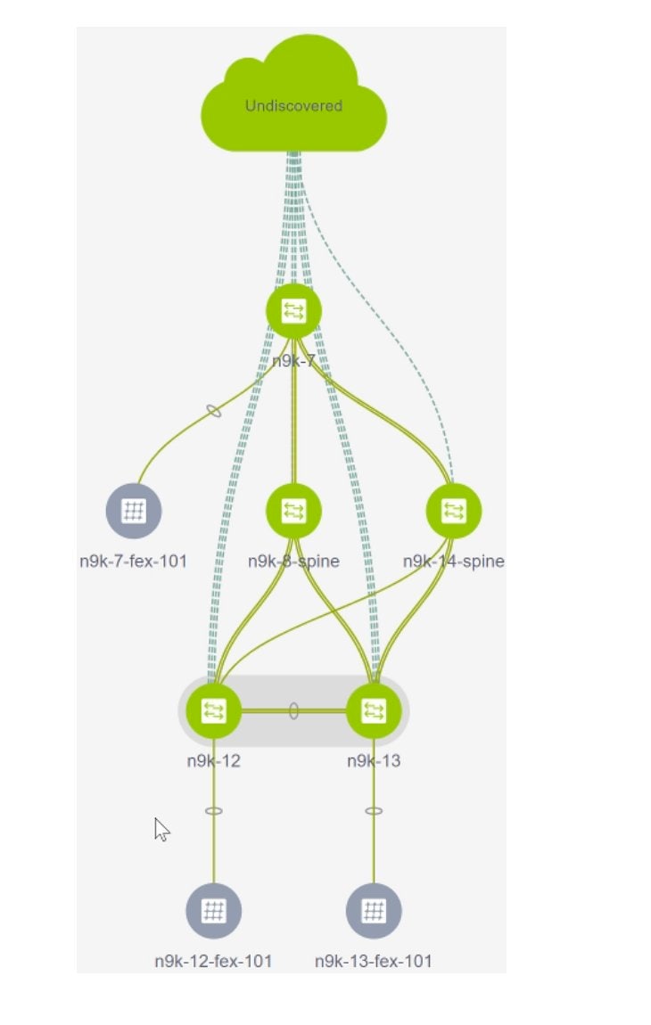
Post-transitioning of VXLAN fabric management to DCNM - This completes the transitioning process of VXLAN fabric management to DCNM. Now, you can add new switches and provision overlay networks for your fabric. For details, refer the respective section in the Fabrics topic in the configuration guide.
Fabric Options
-
Tabular View - By default, the switches are displayed in the topology view. Use this option to view switches in the tabular view.
-
Refresh topology - Allows you to refresh the topology.
-
Save Layout – Saves a custom view of the topology. You can create a specific view in the topology and save it for ease of use.
-
Delete saved layout – Deletes the custom view of the topology
-
Topology views - You can choose between Hierarchical, Random and Custom saved layout display options.
-
Hierarchical - Provides an architectural view of your topology. Various Switch Roles can be defined that draws the nodes on how you configure your CLOS topology.
-
Random - Nodes are placed randomly on the screen. DCNM tries to make a guess and intelligently place nodes that belong together in close proximity.
-
Custom saved layout - You can drag nodes around to your liking. Once you have the positions as how you like, you can click Save Layout to remember the positions. Next time you come to the topology, DCNM will draw the nodes based on your last saved layout positions.
-
-
Restore Fabric – Allows you to restore the fabric to a prior DCNM configuration state (one month back, two months back, and so on). For more information, see Restore Fabric section.
-
Backup Now: You can initiate a fabric backup manually by clicking Backup Now. Enter a name for the tag and click OK. Regardless of the settings you choose under the Configuration Backup tab in the Fabric Settings dialog box, you can initiate a backup using this option.
-
Resync Fabric - Use this option to resynchronize DCNM state when there is a large scale out-of-band change, or if configuration changes do not register in the DCNM properly. The resync operation does a full CC run for the fabric switches and recollects “show run” and “show run all” commands from the switches. When you initiate the re-sync process, a progress message is displayed on the screen. During the re-sync, the running configuration is taken from the switches. The OUT-OF-SYNC/IN-SYNC status for the switches is recalculated based on the intent defined in DCNM.
-
Add Switches – Allows you to add switch instances to the fabric.
-
Fabric Settings – Allows you to view or edit fabric settings.
Migrating a Bottom-Up VXLAN Fabric to DCNM
This procedure shows how to migrate a bottom-up VXLAN fabric to DCNM.
Typically, your fabric is created and managed through manual CLI configuration or custom automation scripts. After the migration, the fabric underlay and overlay networks can be managed by using DCNM.
The guidelines and limitations, and prerequisites for bottom-up VXLAN migration are the same as the Brownfield migration. For more information, see Brownfield Deployment-Transitioning VXLAN Fabric Management to DCNM.
-
Create a VXLAN BGP EVPN fabric.
For more information, see the Creating a New VXLAN BGP EVPN Fabric section in Brownfield Deployment-Transitioning VXLAN Fabric Management to DCNM.
-
Add switch instances to the fabric.
For more information, follow the Step 1 to Step 5 in the Adding Switch Instances and Transitioning VXLAN Fabric Management section in Brownfield Deployment-Transitioning VXLAN Fabric Management to DCNM.
-
Click Save & Deploy to sync configurations between the switches and DCNM.

If the added switches contain bottom-up configurations, an error is displayed saying – Reloading switch to clean up bottom up config. Please wait for switch to come online and try Save & Deploy.
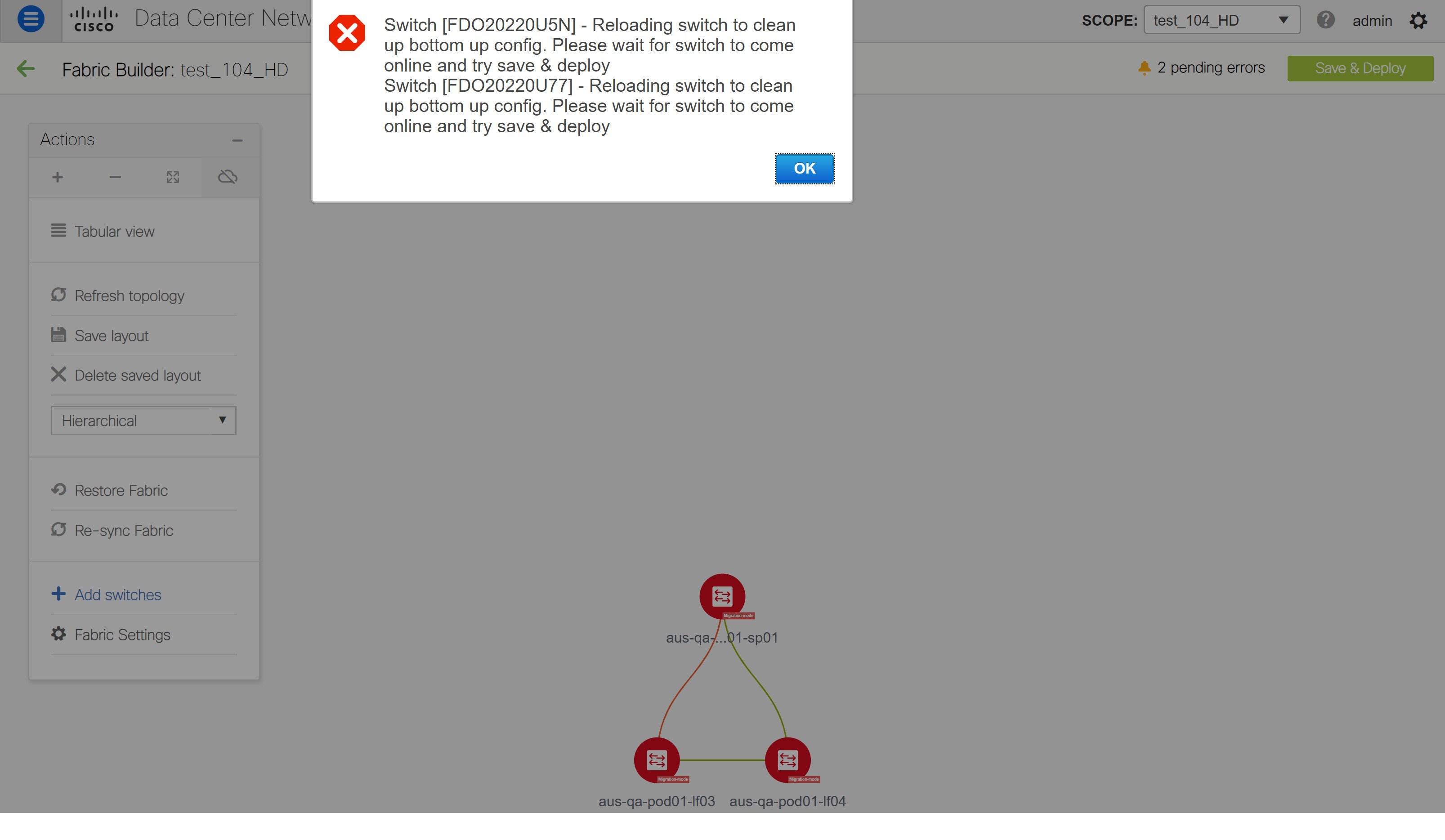
-
Wait for the switches to complete the reload operation. Click Tabular view under the Actions menu to view the status of the switches.
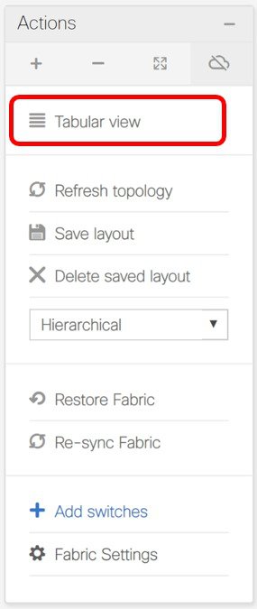
-
(Optional) Rediscovery of the reloaded switches occurs every 5 minutes. If you want to manually rediscover switches, select the switches and click the Rediscover switch icon.
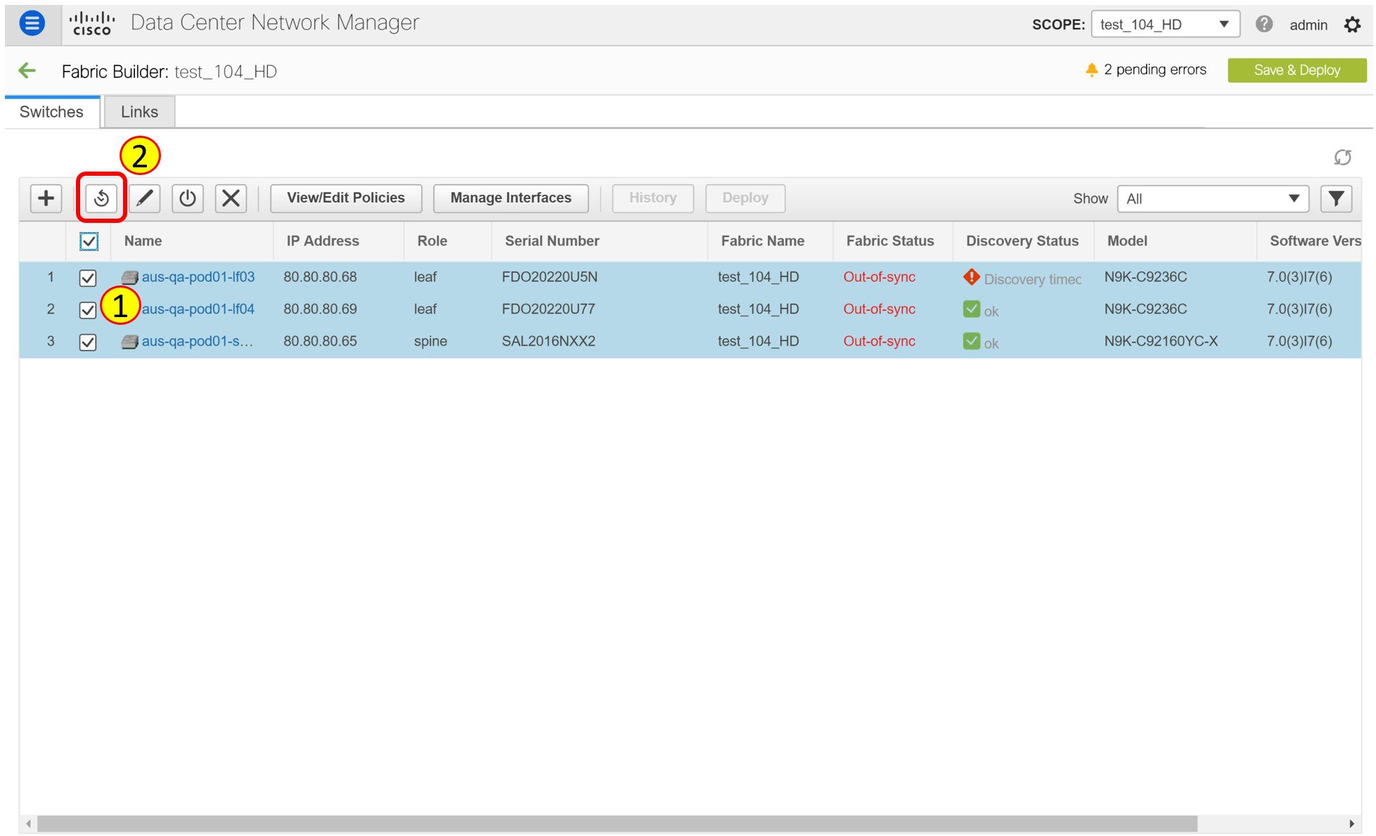
Note
Click the Refresh icon to refresh the Fabric Builder window and see the updated discovery status of switches.
-
Check the Discovery Status of the switches after the reloading and rediscovering operations are completed. Make sure that the status for all the switches is ok.
Note
When a switch is in Unreachable discovery status, the last available information of the switch is retained in other columns. For example, if the switch was in RUNNING tracker status before it becomes unreachable, the value under the Tracker Status column for this switch will still be RUNNING despite the switch being in Unreachable discovery status.
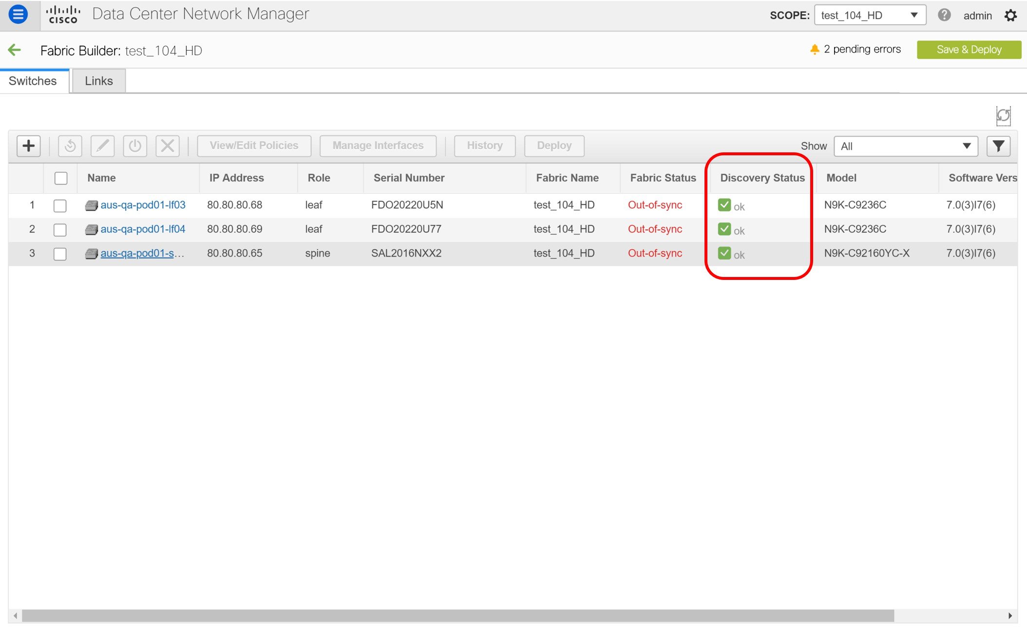
-
Click Save & Deploy again to sync configurations between the switches and DCNM.
The Saving Fabric Configuration message comes up immediately. This indicates that overlay and underlay network migration, and switch and port channel settings migration to DCNM is initiated.
After the migration of underlay and overlay networks, the Config Deployment window is displayed.
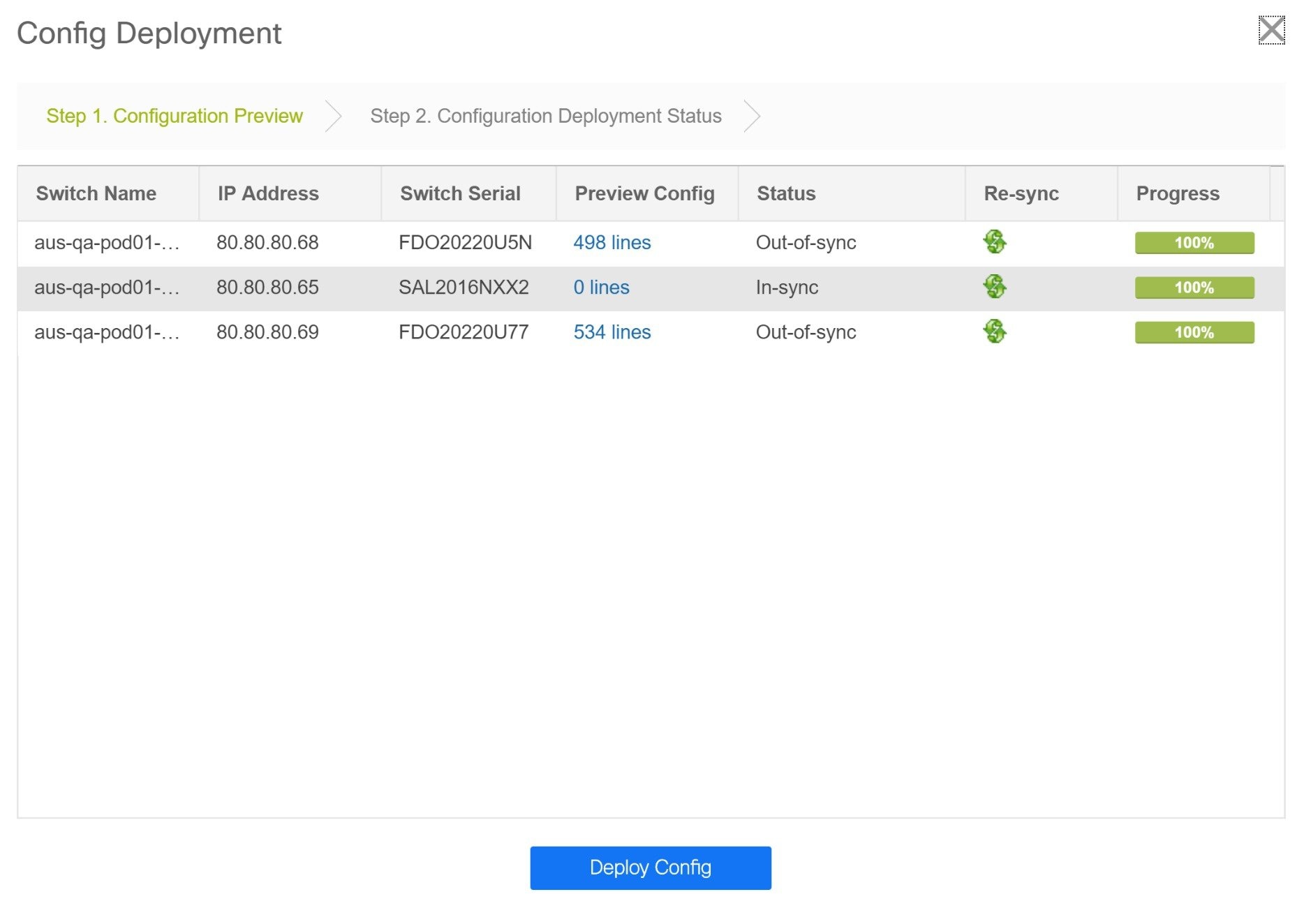
The Preview Config column is updated with entries denoting a specific number of lines.
We strongly recommend that you preview the configuration before proceeding to deploy it on the switches. Click a Preview Config column entry. The Config Preview window is displayed. This window lists the pending configurations on the switch. The Side-by-side Comparison tab displays the running configuration and expected configuration side-by-side.
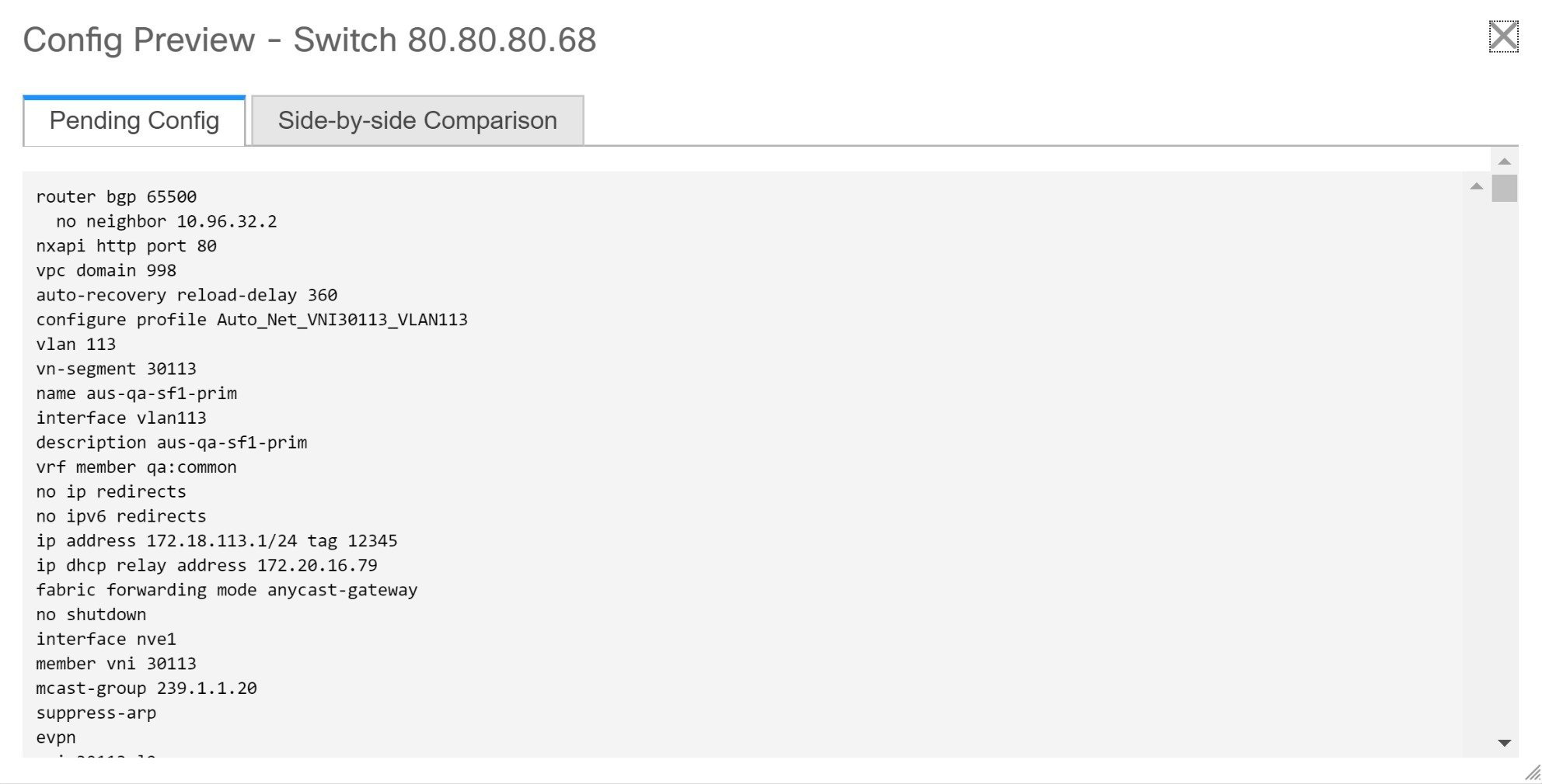
Close the Config Preview window.
-
Click Deploy Config at the bottom part of the Config Deployment window to initiate pending configuration onto the switch. The Status column displays the completion state. For a failed state, investigate the reason for failure to address the issue.
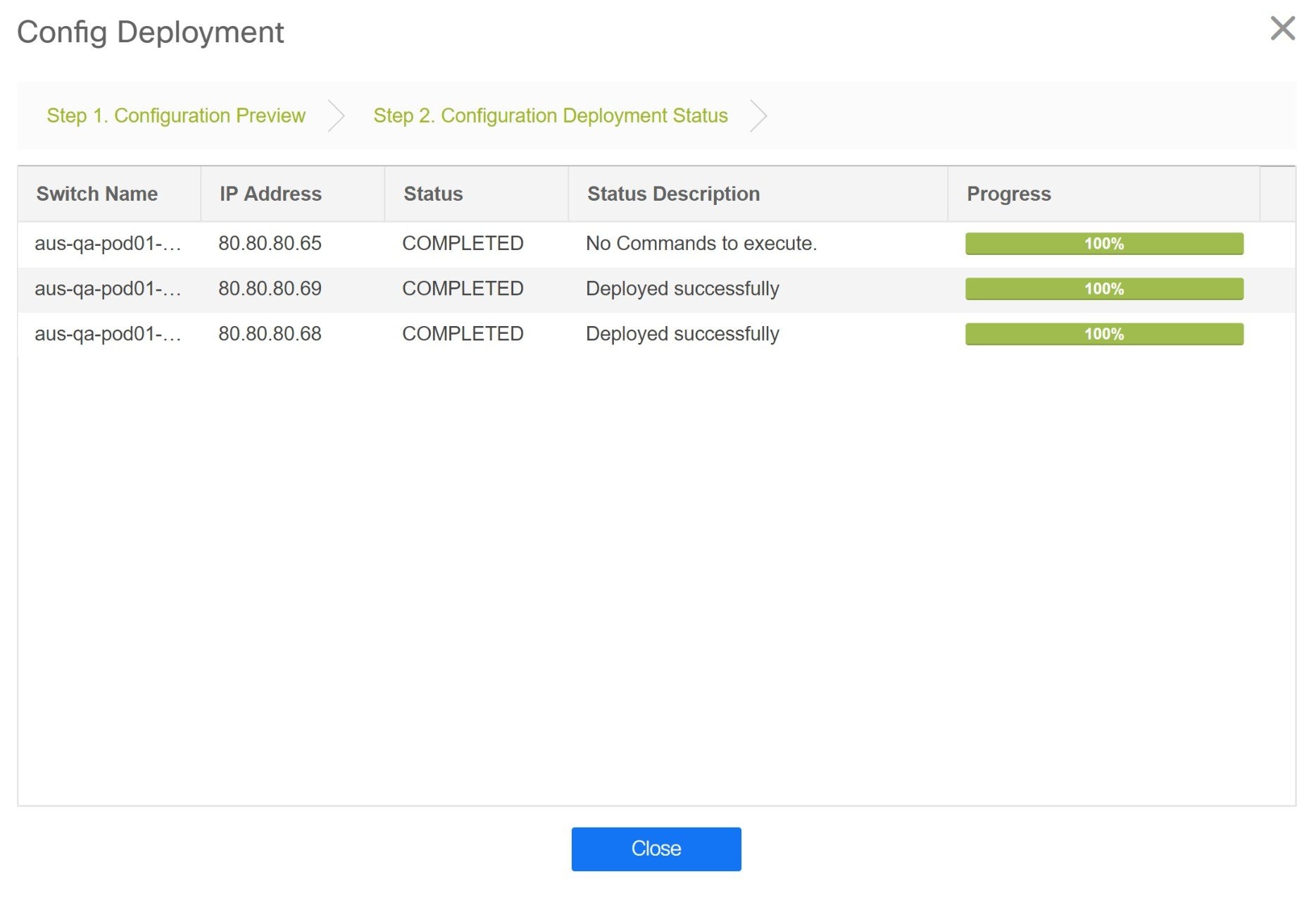
The progress bar shows 100% for each switch. After correct provisioning and successful configuration compliance, close the Config Deployment window.
In the fabric topology window, all imported switch instances are displayed in green color, indicating successful configuration. Also, the Migration Mode label is not displayed on any switch icon.
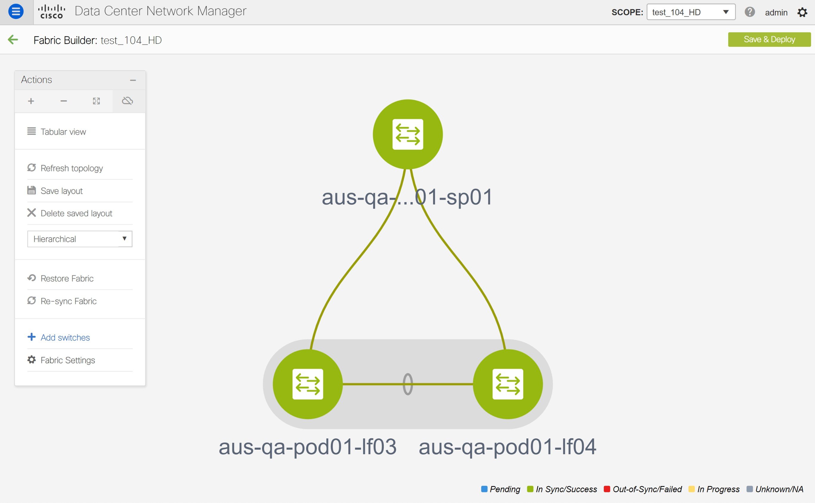
This completes the migration process of bottom-up VXLAN fabric to DCNM.
Now, you can add new switches and provision overlay networks for your fabric. For details, refer the respective section in the Fabrics topic in the configuration guide.
You can also verify the migrated networks by following the below steps.
-
Choose Control > Fabrics > Networks.

-
Select the fabric from the SCOPE drop-down list in the Networks window.
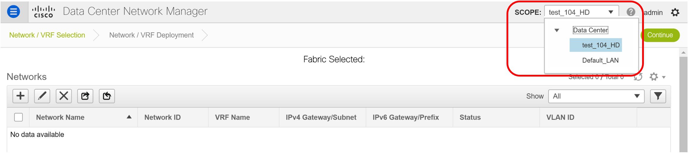
-
Check the networks that are migrated from the bottom-up VXLAN fabric and their deployment status.
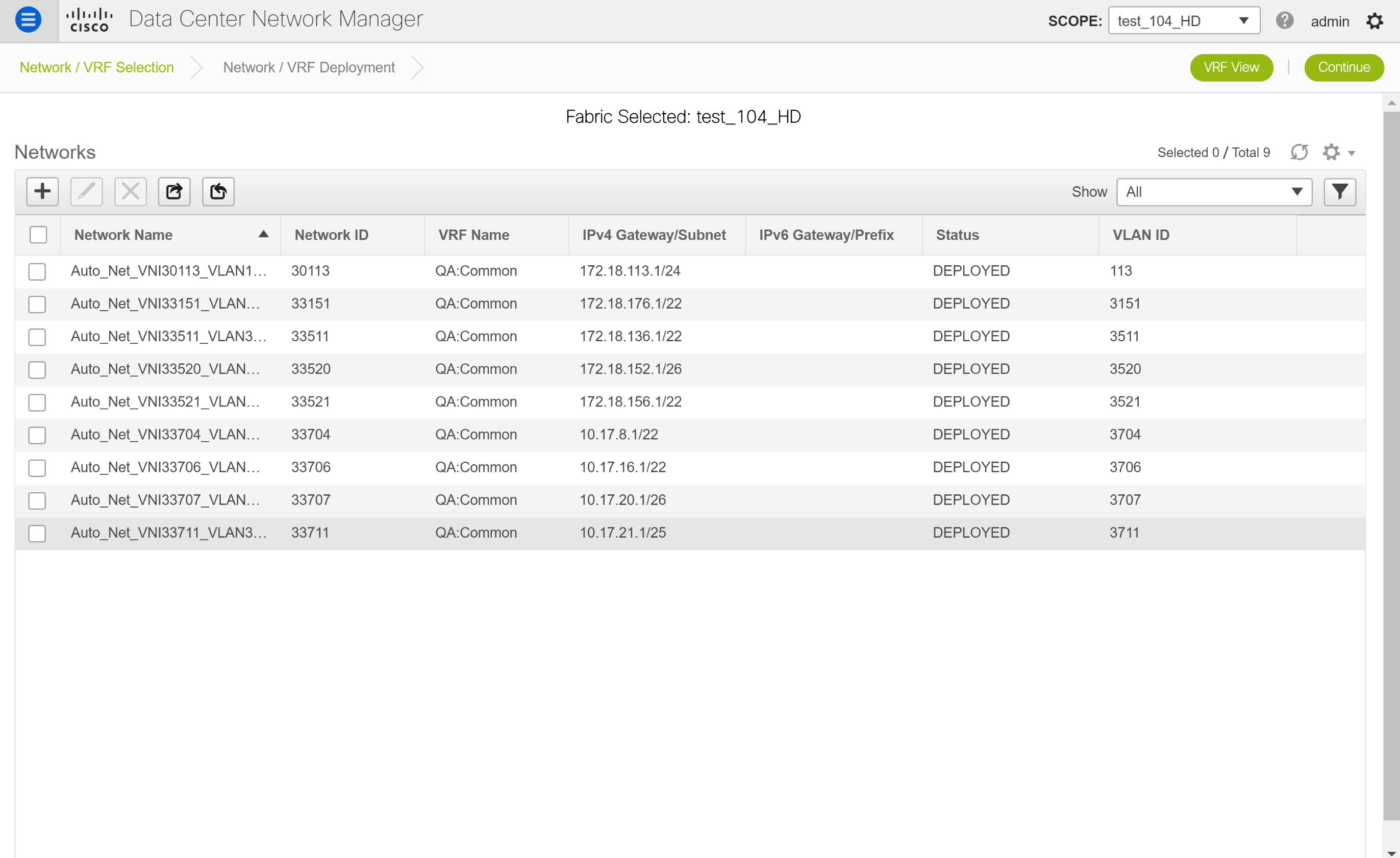
Resolving Config Compliance Error on Switches with Cisco NX-OS Release 7.0(3)I4(8b) and 7.0(4)I4(x) Images
After brownfield deployment of Cisco Nexus 9300 Series switches and Cisco Nexus 9500 Series switches with X9500 line cards with Cisco NX-OS Release 7.0(3)I4(8b) and 7.0(4)I4(x) images, config compliance difference is displayed. You need to remove the tcam_pre_config_vxlan policy from these switches to resolve the config compliance error.
The following procedure shows how to remove the tcam_pre_config_vxlan policy from switches after brownfield deployment.
-
Choose Control > Fabrics > Fabric Builder.
-
Click the brownfield fabric that contains a Cisco Nexus 9300 Series switch or Cisco Nexus 9500 Series switches with X9500 line cards in the Fabric Builder window.
-
(Optional) Click Save & Deploy to see the Config Compliance error.
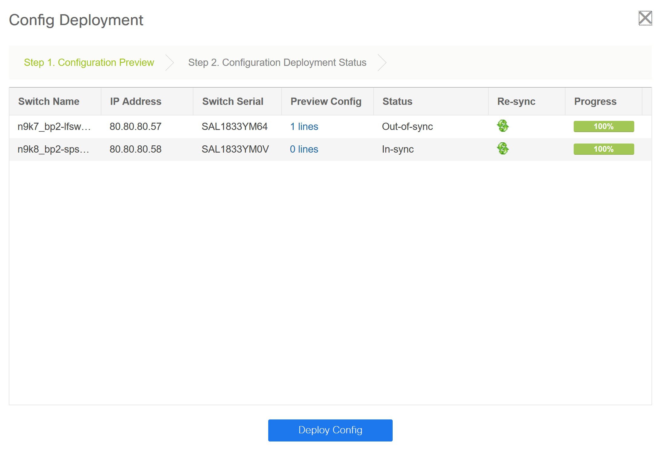
-
(Optional) Click the entry showing 1 lines under the Preview Config column.
You can see the TCAM command under the Pending Config tab in the Config Preview window.
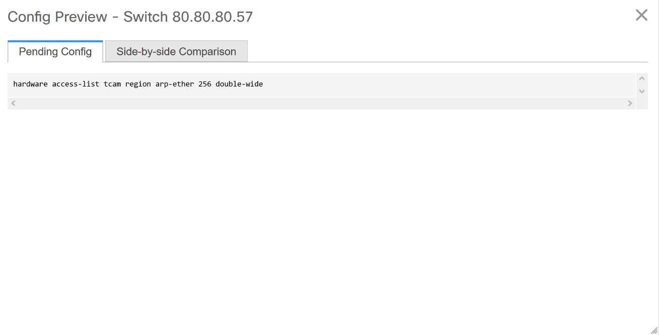
Close the Config Preview window.
-
Right-click a switch and click View/Edit Policies.
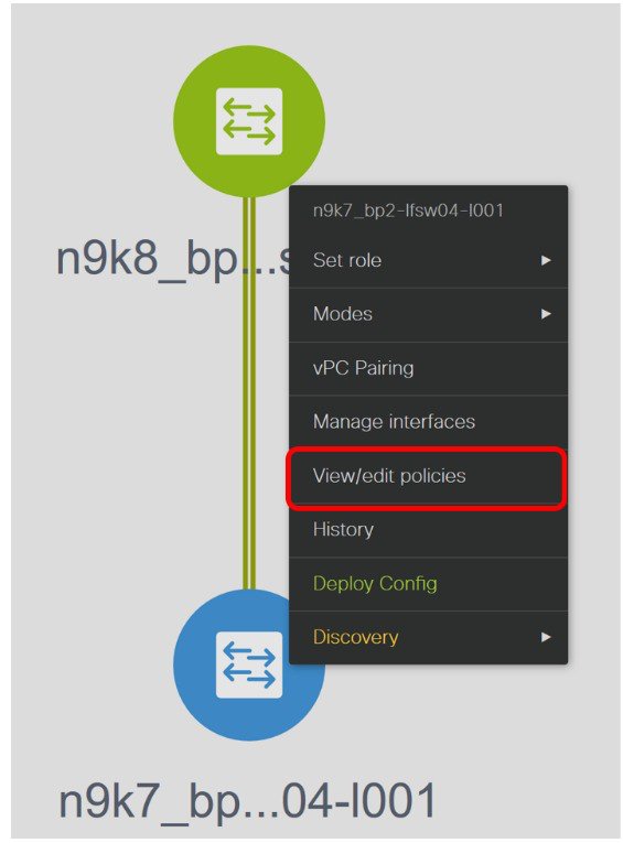
-
Search for the tcam_pre_config_vxlan policy in the Template search field.
-
Select the tcam_pre_config_vxlan policy and click the Delete icon to delete the policy.
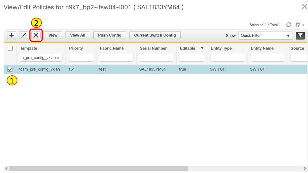
Close the View/Edit Policies window.
-
(Optional) Click Save & Deploy to verify whether there are any pending configs.
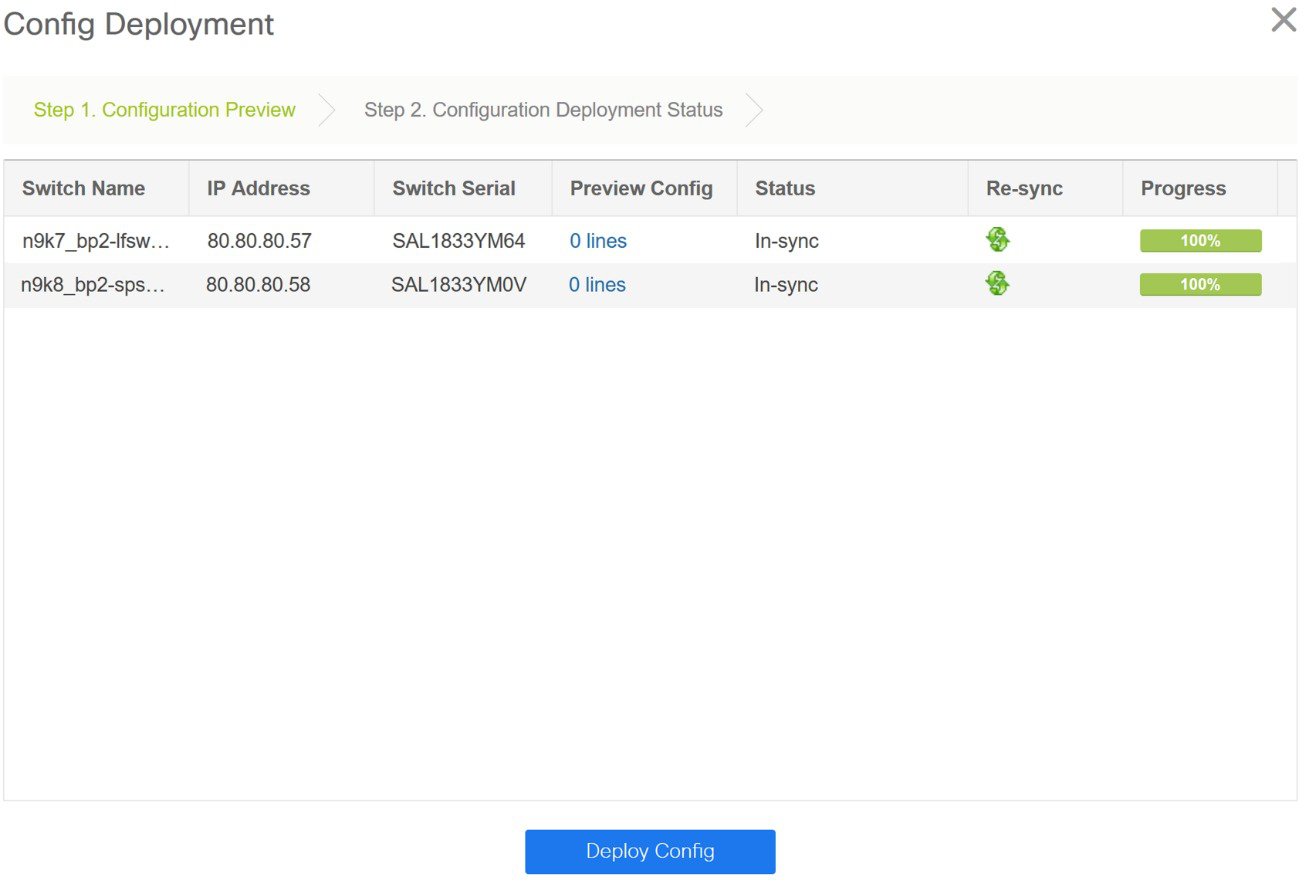
Perform the following procedure before you perform RMA or Write Erase and Reload operation on Cisco Nexus 9300 Series switches and Cisco Nexus 9500 Series switches with X9500 line cards with the Cisco NX-OS Release 7.0(3)I4(8b) and 7.0(4)I4(x) images.
-
Choose Control > Fabrics > Fabric Builder.
-
Click the brownfield fabric that contains the specified switches with Cisco images.
-
Right-click the switch and click View/Edit Policies.
-
Click the Add icon.
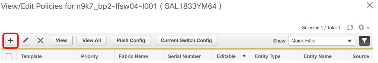
-
Enter 151 in the Priority (1-1000) field and select tcam_pre_config_vxlan from the Policy drop-down list.
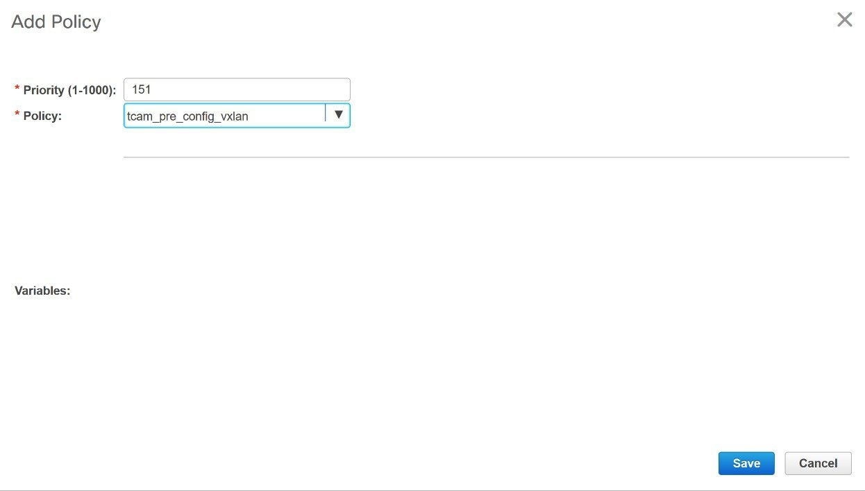
-
Click Save.
-
Complete the RMA or Write Erase and Reload operation.
After the switch is online, it will be out-of-sync.
-
Right-click a switch and click View/Edit Policies.
-
Search for the tcam_pre_config_vxlan policy in the Template search field.
-
Select the tcam_pre_config_vxlan policy and click the Delete icon to delete the policy.
Close the View/Edit Policies window.
Modifying VLAN Names in a Switch with Cisco NX-OS Release 7.0(3)I4(8b) and 7.0(4)I4(x) Images
Post brownfield migration, the VLAN name for the network or VRF is not captured in the overlay profile if at least one of the non-spine switches have the Cisco NX-OS Release 7.0(3)I4(8b) and 7.0(4)I4(x) images.
This procedure shows how to check the VLAN name and modify it.
-
Choose Control > Fabrics > Networks.
-
From the SCOPE drop-down list, select a fabric containing the non-spine switches with the Cisco NX-OS Release 7.0(3)I4(8b) and 7.0(4)I4(x) images.
-
Select a check box for a network in the Networks window and click the Edit Network icon.
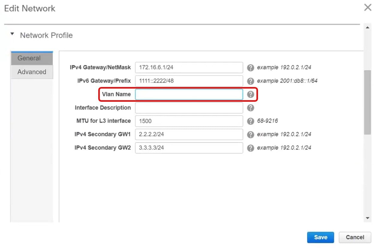
In the Edit Network window, the Vlan Name field is empty because DCNM has not captured this info in the overlay profile. Instead, the VLAN name is captured in the freeform config associated with the overlay network or VRF.
Note
If a VLAN did not have a name before the brownfield migration, you can add the name in the Vlan Name field in the Edit Network window.
Close the Edit Network window.
-
Click Continue in the Networks window.
-
Double-click a switch in the Topology View window.
-
In the Network Attachment window for a switch, click the Freeform config button under the CLI Freeform column.
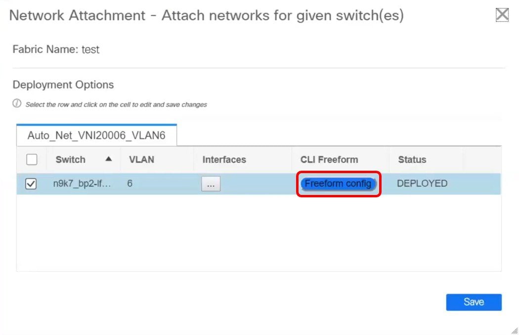
-
Verify the VLAN name in the Free Form Config window.
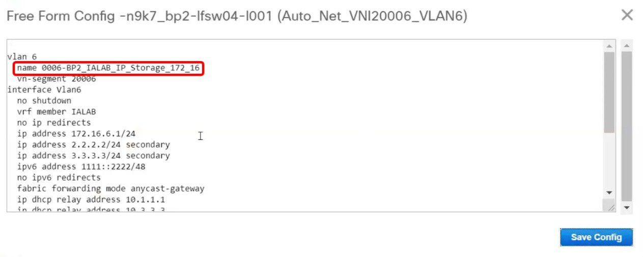
-
Modify the VLAN name in the Free Form Config window and click Save Config.
Here is an example:
vlan 6
  name Storage_172_16_Deb
  vn-segment 20006
interface Vlan6
.
.
.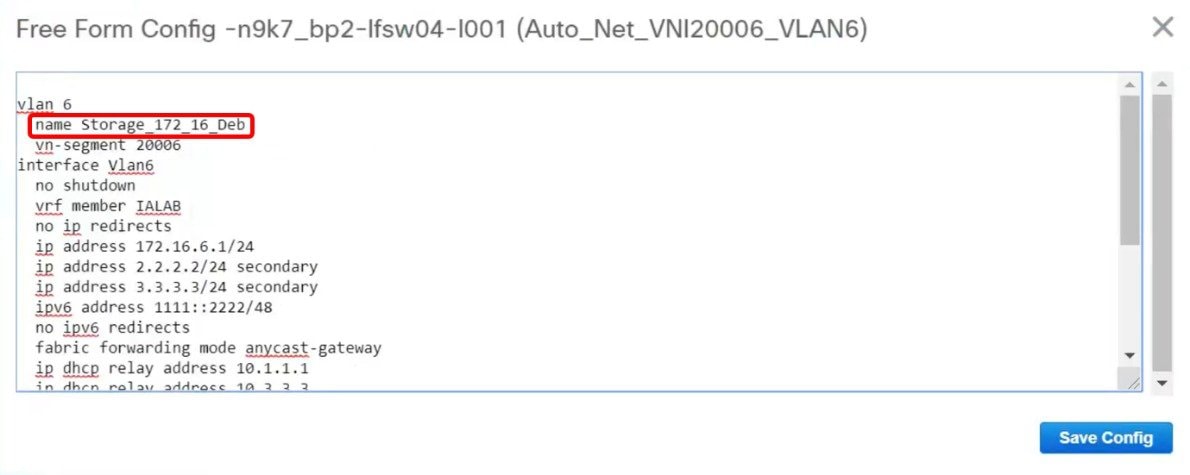
-
Click Save in the Network Attachment window.
-
Click Deploy in the Networks window.
The modified VLAN name in the selected network is deployed on the switch.
Changing a Brownfield Imported BIDIR Configuration
This procedure shows how to change a brownfield imported BIDIR configuration to use the configuration generated by Fabric Builder.
-
Choose Control > Fabrics > Networks.
-
Click the brownfield fabric.
-
Click Tabular View under the Actions Panel in the Fabric Builder window.
-
Select all the devices and click the View/Edit Policies icon.
-
Delete the following policies for all the devices in the View/Edit Policies window
-
base_pim_bidir_11_1
-
If there is 1 RP in the fabric, delete the rp_lb_id policy.
If there are 2 RPs in the fabric, delete the phantom_rp_lb_id1 and phantom_rp_lb_id2 policies.
-
-
Close the View/Edit Policies window.
-
Click the Manage Interfaces button in the Fabric Builder window.
-
Delete all the RP loopback interfaces in the Interfaces window and close this window.
-
Click Save & Deploy in the Fabric Builder window.
This action generates a new set of BIDIR-related configuration based on the fabric settings for the devices.
Manually Adding PIM-BIDIR Configuration for Leaf or Spine Post Brownfield Migration
After brownfield migration, if you add new spine or leaf switches, you should manually configure the PIM-BIDIR feature.
The following procedure shows how to manually configure the PIM-BIDIR feature for a new Leaf or Spine:
-
Check the base_pim_bidir_11_1 policies that are created for an RP added through the brownfield migration. Check the RP IP and Multicast Group used in each ip pim rp-address RP_IP group-list MULTICAST_GROUP bidir command.
-
Add respective base_pim_bidir_11_1 policies from the View/Edit Policies window for the new Leaf or Spine, push the config for each base_pim_bidir_11_1 policy.
Configuration Profiles Support for Brownfield Migration
Cisco DCNM Release 11.3(1) supports the Brownfield import of fabrics with VXLAN overlay provisioned with configuration profiles. This import process recreates the overlay configuration intent based on the configuration profiles. The underlay migration is performed with the usual Brownfield migration.
The support for the configuration profiles is useful in the following cases:
-
Moving a fabric from an older version of DCNM to a newer version of DCNM when the upgrade is not feasible. Typically, you must install the latest DCNM release, create a fabric, and then import the switches into the fabric.
-
Splitting a single large fabric deployment into smaller deployments. You create a new fabric, delete switches from the large fabric deployment, and import it into the new fabric.
The following are the guidelines for the support of configuration profiles:
-
The Brownfield migration of configuration profiles is supported for the Easy_Fabric_11_1 template.
-
The configuration profiles on the switches must be a subset of the default overlay Universal profiles. If extra configuration lines are present that are not part of the Universal profiles, unwanted profile refreshes will be seen. In this case, after you click Save & Deploy, review the diffs using the Side-by-side Comparison feature and deploy the changes.
-
Brownfield migration with switches having a combination of VXLAN overlay configuration profiles and regular CLIs is not supported. If this condition is detected, an error is generated, and migration is aborted. All the overlays must be with either configuration profiles or regular CLIs only.
Migrating an MSD Fabric with Border Gateway Switches
When you migrate an existing MSD fabric with a border gateway switch into DCNM, make sure to note the following guidelines:
-
Underlay Multisite peering: The eBGP peering and corresponding routed interfaces for underlay extensions between sites are captured in switch_freeform and routed_inerfaces, and optionally in the interface_freeform configs. This configuration includes all the global configs for multisite. Loopbacks for EVPN multisite are also captured via the appropriate interface templates.
-
Overlay Multisite peering: The eBGP peering is captured as part of switch_freeform as the only relevant config is under router bgp.
-
Overlays containing Networks or VRFs: The corresponding intent is captured with the profiles on the Border Gateways with extension_type = MULTISITE.
This ensures that the brownfield migration will be complete with no CC diff, and there will be no traffic disruption.
Perform the following steps after you migrate the member fabrics into DCNM:
Before you begin, ensure member fabrics have the correct Site ID in the fabric settings.
-
Create an MSD. For more information, see Creating an MSD Fabric.
-
Ensure that the fabric settings for MSD are correct including settings such as profile selection, the multisite loopback ID, and anycast GW MAC.
-
Move the member fabrics into the MSD. For more information, see Moving the Member1 Fabric Under MSD-Parent-Fabric.
Note
The networks or VRFs definitions should be symmetric. Otherwise, you will not be able to deploy Multi-Site. If there are any errors based on conflicting definitions for VRFs or networks, you need to resolve before deployment.
-
Create multisite overlay IFC. For more information, see Configuring Multi-Site Overlay IFCs.
Multisite overlay IFCs need to be created if Multi-Site Overlay IFC Deployment Method is set to Manual under the DCI tab for the MSD fabric settings.
If Multi-Site Overlay IFC Deployment Method is set to Direct_To_BGWS, then overlay IFCs are created after brownfield migration, and associated with appropriate MULTISITE_OVERLAY policy.
The intent generated by this IFC should match what was captured in the freeform for the MULTISITE_IFC for BGP peering.
Repeat the above step for each BGW MULTISITE_OVERLAY IFC and for each member fabric. After the Multi-Site overlay IFCs are successfully created, the intent for the eBGP multisite overlay peering captured in the freeform policy templates for the BGWs can be removed. Otherwise, the intent for the eBGP multisite overlay peering is captured twice.
Note that there is no need to create MULTISITE_UNDERLAY IFCs as they have already been captured in the intent.
-
To verify, you can select networks or VRFs and corresponding BGWs, and see the expected configurations. You can now manage all the networks or VRFs for BGWs by using the regular top-down workflow.
Creating a New Fabric for EBGP-Based Underlay
-
Choose Control > Fabric Builder.
The Fabric Builder screen appears. When you log in for the first time, the Fabrics section has no entries. After you create a fabric, it is displayed on the Fabric Builder screen, wherein a rectangular box represents each fabric.
A standalone or member fabric contains Switch_Fabric (in the Type field), the AS number (in the ASN field), and mode of replication (in the Replication Mode field).
The technology is for a fabric with eBGP Routed Fabric or eBGP VXLAN EVPN Fabric. The mode of replication is only applicable for the eBGP VXLAN EVPN fabric, and not eBGP Routed fabric.
-
Click Create Fabric. The Add Fabric screen appears.
The fields are explained:
Fabric Name - Enter the name of the fabric.
Fabric Template - From the drop-down menu, choose the Easy_Fabric_eBGP fabric template. The fabric settings for creating a standalone routed fabric comes up.
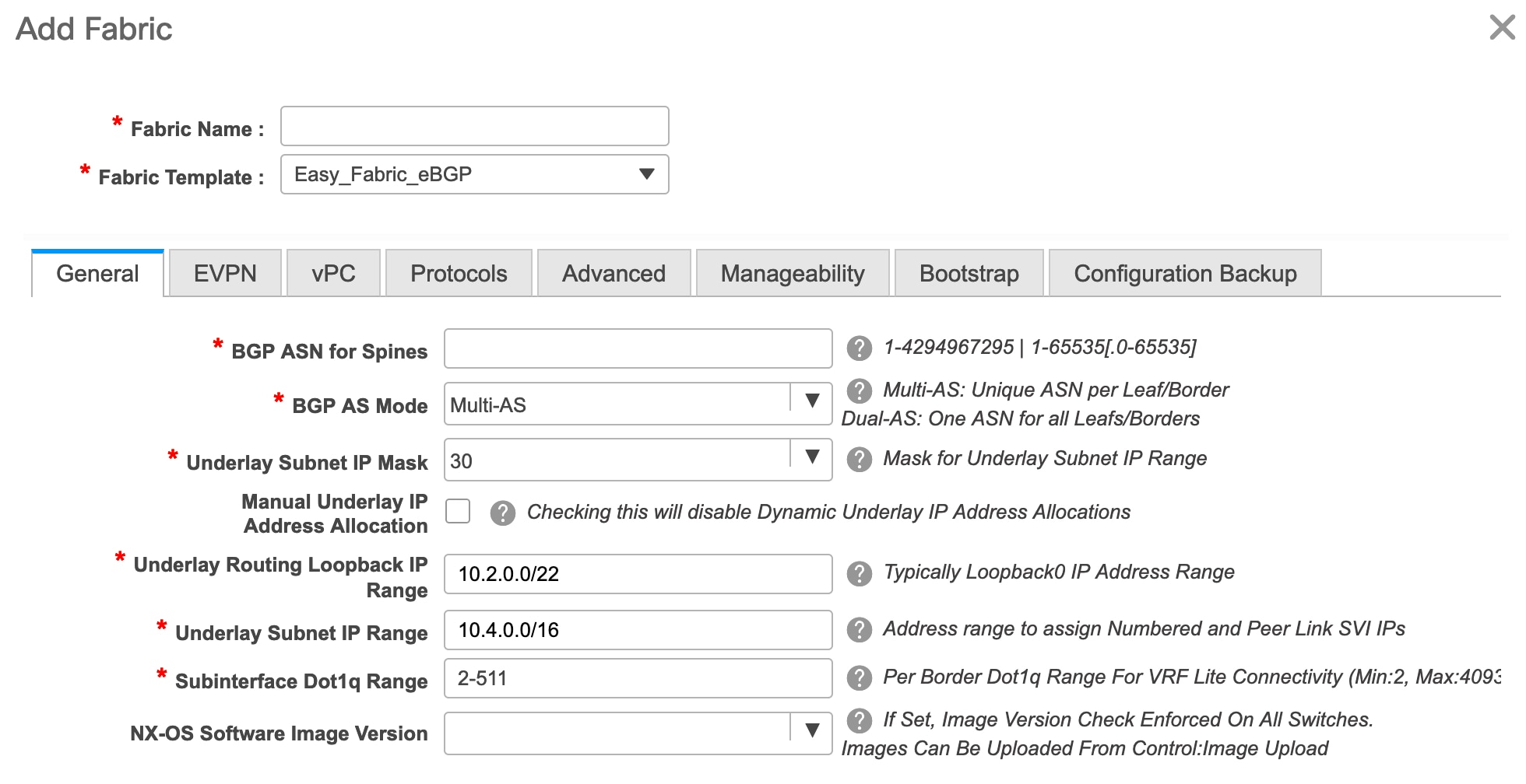
- The General tab is displayed by default. The fields in this tab are:
BGP ASN for Spines: Enter the BGP AS number of the fabric’s spine switches.
BGP AS Mode: Choose Multi-AS or Dual-AS.
In a Multi-AS fabric, the spine switches have a unique BGP AS number and each leaf switch has a unique AS number. If two leaf switches form a vPC switch pair, then they have the same AS number.
In a Dual-AS fabric, the spine switches have a unique BGP AS number and the leaf switches have a unique AS number.
The fabric is identified by the spine switch AS number.
Underlay Subnet IP Mask - Specifies the subnet mask for the fabric interface IP addresses.
Manual Underlay IP Address Allocation – Select this check box to disable Dynamic Underlay IP Address Allocations.
Underlay Routing Loopback IP Range: Specifies loopback IP addresses for the protocol peering.
Underlay Subnet IP Range: IP addresses for underlay P2P routing traffic between interfaces.
Subinterface Dot1q Range: Specifies the subinterface range when L3 sub interfaces are used.
NX-OS Software Image Version: Select an image from the drop-down list.
If you upload Cisco NX-OS software images through the image upload option, the uploaded images are listed in this field. If you select an image, the system checks if the switch has the selected version. If not, an error message is displayed. You can resolve the error by clicking on Resolve. The image management screen comes up and you can proceed with the ISSU option. Alternatively, you can delete the release number and save it later.
If you specify an image in this field, all switches in the fabric should run that image. If some devices do not run the image, a warning is prompted to perform an In-Service Software Upgrade (ISSU) to the specified image. Till all devices run the specified image, the deployment process will be incomplete.
If you want to deploy more than one type of software image on the fabric switches, don’t specify any image. If an image is specified, delete it.
-
Click EVPN. Most of the fields in this tab are auto-populated. The fields are:
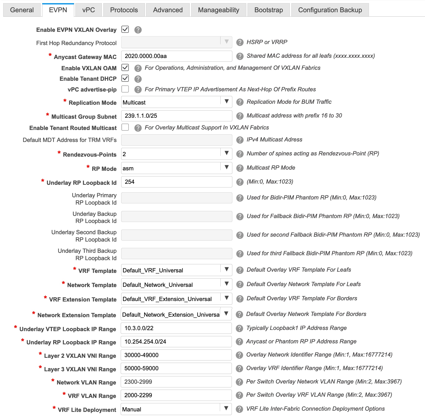
Enable EVPN VXLAN Overlay: Enables the VXLAN overlay provisioning for the fabric.
You can convert a routed fabric to a VXLAN enabled fabric by selecting this option. When the fabric is VXLAN enabled, you can create and deploy overlay networks or VRFs. The procedure for creating and deploying networks or VRFs is the same as in Easy_Fabric_11_1.
Note
The rest of the fields in the EVPN tab section are only applicable if you enable the EVPN VXLAN Overlay.
Routed Fabric: You must disable the Enable EVPN VXLAN Overlay field for Routed fabric (an IP fabric with no VXLAN encapsulation) creation.
Whether you create an eBGP Routed or eBGP VXLAN fabric, the fabric uses eBGP as the control plane to build intra-fabric connectivity. Links between spine and leaf switches are autoconfigured with point-to-point (p2p) numbered IP addresses with eBGP peering built on top.
If a network or a VRF is created in a fabric, you cannot switch between VXLAN EVPN mode and Routed Fabric mode by selecting the Enable EVPN VXLAN Overlay check box. You need to delete these networks or VRFs to change the fabric setting.
First Hop Redundancy Protocol: Specifies the FHRP protocol. Choose either hsrp or vrrp.
Note
After a network has been created, you cannot change this fabric setting. You should delete all networks, and then change the FHRP setting.
Anycast Gateway MAC: Anycast gateway MAC address for the leaf switches.
Enable VXLAN OAM: Enables the VXLAM OAM function for existing switches. This is enabled by default. Clear the check box to disable VXLAN OAM function.
If you want to enable the VXLAN OAM function on specific switches and disable on other switches in the fabric, you can use freeform configurations to enable OAM and disable OAM in the fabric settings.
Note
The VXLAN OAM feature in Cisco DCNM is only supported on a single fabric or site.
Enable Tenant DHCP: Enables tenant DHCP support.
vPC advertise-pip: Check the check box to enable the Advertise PIP feature.
Replication Mode : The mode of replication that is used in the fabric, Ingress Replication, or Multicast.
Multicast Group Subnet: IP address prefix used for multicast communication. A unique IP address is allocated from this group for each overlay network.
Enable Tenant Routed Multicast: Check the check box to enable Tenant Routed Multicast (TRM) as the fabric overlay multicast protocol.
Default MDT Address for TRM VRFs: The multicast address for Tenant Routed Multicast traffic is populated. By default, this address is from the IP prefix specified in the Multicast Group Subnet field. When you update either field, ensure that the TRM address is chosen from the IP prefix specified in Multicast Group Subnet.
Rendezvous-Points: Enter the number of spine switches acting as rendezvous points.
RP mode: Choose from the two supported multicast modes of replication, ASM (for Any-Source Multicast [ASM]) or BiDir (for Bidirectional PIM [BIDIR-PIM]). When you choose ASM, the BiDir related fields are not enabled. When you choose BiDir, the BiDir related fields are enabled.
Note
BIDIR-PIM is supported on Cisco's Cloud Scale Family platforms 9300-EX and 9300-FX/FX2, and software release 9.2(1) onwards.
Underlay RP Loopback ID: The loopback ID used for the rendezvous point (RP), for multicast protocol peering purposes in the fabric underlay. The default is 254.
The following fields are enabled if you choose bidir. Depending on the RP count, either 2 or 4 phantom RP loopback ID fields are enabled.
-
Underlay Primary RP Loopback ID: The primary loopback ID used for the phantom RP, for multicast protocol peering purposes in the fabric underlay.
-
Underlay Backup RP Loopback ID: The secondary (or backup) loopback ID used for the phantom RP, for multicast protocol peering purposes in the fabric underlay.
The following Loopback ID options are applicable only when the RP count is 4.
-
Underlay Second Backup RP Loopback ID: The second backup loopback ID used for the phantom RP, for multicast protocol peering purposes in the fabric underlay.
-
Underlay Third Backup RP Loopback ID: The third backup loopback ID used for the phantom RP, for multicast protocol peering purposes in the fabric underlay.
VRF Template and VRF Extension Template: Specifies the VRF template for creating VRFs, and the VRF extension template for enabling VRF extension to other fabrics.
Network Template and Network Extension Template: Specifies the network template for creating networks, and the network extension template for extending networks to other fabrics.
Underlay VTEP Loopback IP Range: Specifies the loopback IP address range for VTEPs.
Underlay RP Loopback IP Range: Specifies the anycast or phantom RP IP address range.
Layer 2 VXLAN VNI Range and Layer 3 VXLAN VNI Range: Specifies the VXLAN VNI IDs for the fabric.
Network VLAN Range and VRF VLAN Range: VLAN ranges for the Layer 3 VRF and overlay network.
VRF Lite Deployment: Specifies the VRF Lite method for extending inter fabric connections. Only the 'Manual' option is supported.
-
-
Click vPC. The fields in the tab are:
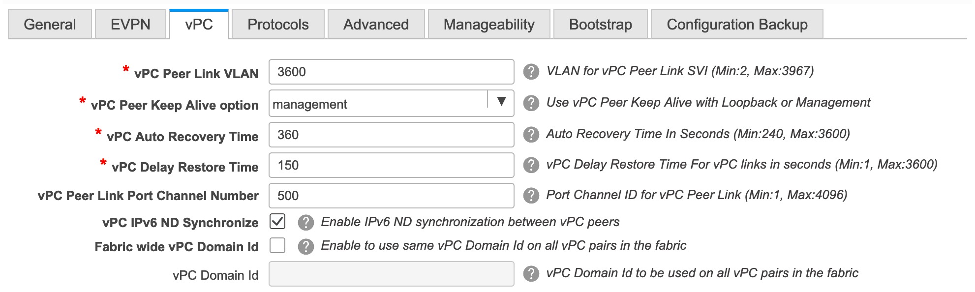
vPC Peer Link VLAN: VLAN used for the vPC peer link SVI.
vPC Peer Keep Alive option: Choose the management or loopback option. If you want to use IP addresses assigned to the management port and the management VRF, choose management. If you use IP addresses assigned to loopback interfaces (and a non-management VRF), choose loopback. If you use IPv6 addresses, you must use loopback IDs.
vPC Auto Recovery Time: Specifies the vPC auto recovery time-out period in seconds.
vPC Delay Restore Time: Specifies the vPC delay restore period in seconds.
vPC Peer Link Port Channel Number - Specifies the Port Channel ID for a vPC Peer Link. By default, the value in this field is 500.
vPC IPv6 ND Synchronize: Enables IPv6 Neighbour Discovery synchronization between vPC switches. The check box is enabled by default. Clear the check box to disable the function.
Fabric wide vPC Domain Id: Enables the usage of same vPC Domain Id on all vPC pairs in the fabric. When you select this field, the vPC Domain Id field is editable.
vPC Domain Id - Specifies the vPC domain ID to be used on all vPC pairs.
-
Click the Protocols tab. The fields in the tab are:
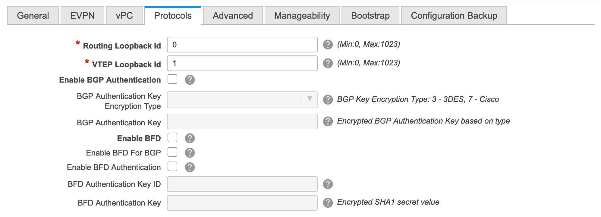
Routing Loopback Id - The loopback interface ID is populated as 0 by default. It is used as the BGP router ID.
VTEP Loopback Id - The loopback interface ID is populated as 1 since loopback1 is usually used for the VTEP peering purposes.
Enable BGP Authentication: Select the check box to enable BGP authentication. Deselect the check box to disable it. If you enable this field, the BGP Authentication Key Encryption Type and BGP Authentication Key fields are enabled.
BGP Authentication Key Encryption Type: Choose the 3 for 3DES encryption type, or 7 for Cisco encryption type.
BGP Authentication Key: Enter the encrypted key based on the encryption type.
Note
Plain text passwords are not supported. Login to the switch, retrieve the encrypted key and enter it in the BGP Authentication Key field. Refer the Retrieving the Authentication Key section for details.
Enable BFD: Select the check box to enable feature bfd on all switches in the fabric. This feature is valid only on IPv4 underlay and the scope is within a fabric.
From Cisco DCNM Release 11.3(1), BFD within a fabric is supported natively. The BFD feature is disabled by default in the Fabric Settings. If enabled, BFD is enabled for the underlay protocols with the default settings. Any custom required BFD configurations must be deployed via the per switch freeform or per interface freeform policies.
The following config is pushed after you select the Enable BFD check box:
feature bfdFor information about BFD feature compatibility, refer your respective platform documentation and for information about the supported software images, see Compatibility Matrix for Cisco DCNM.
Enable BFD for BGP: Select the check box to enable BFD for the BGP neighbor. This option is disabled by default.
Enable BFD Authentication: Select the check box to enable BFD authentication. If you enable this field, the BFD Authentication Key ID and BFD Authentication Key fields are editable.
BFD Authentication Key ID: Specifies the BFD authentication key ID for the interface authentication.
BFD Authentication Key: Specifies the BFD authentication key.
For information about how to retrieve the BFD authentication parameters, see Retrieving the Encrypted BFD Authentication Key.
-
Click the Advanced tab. The fields in the tab are:
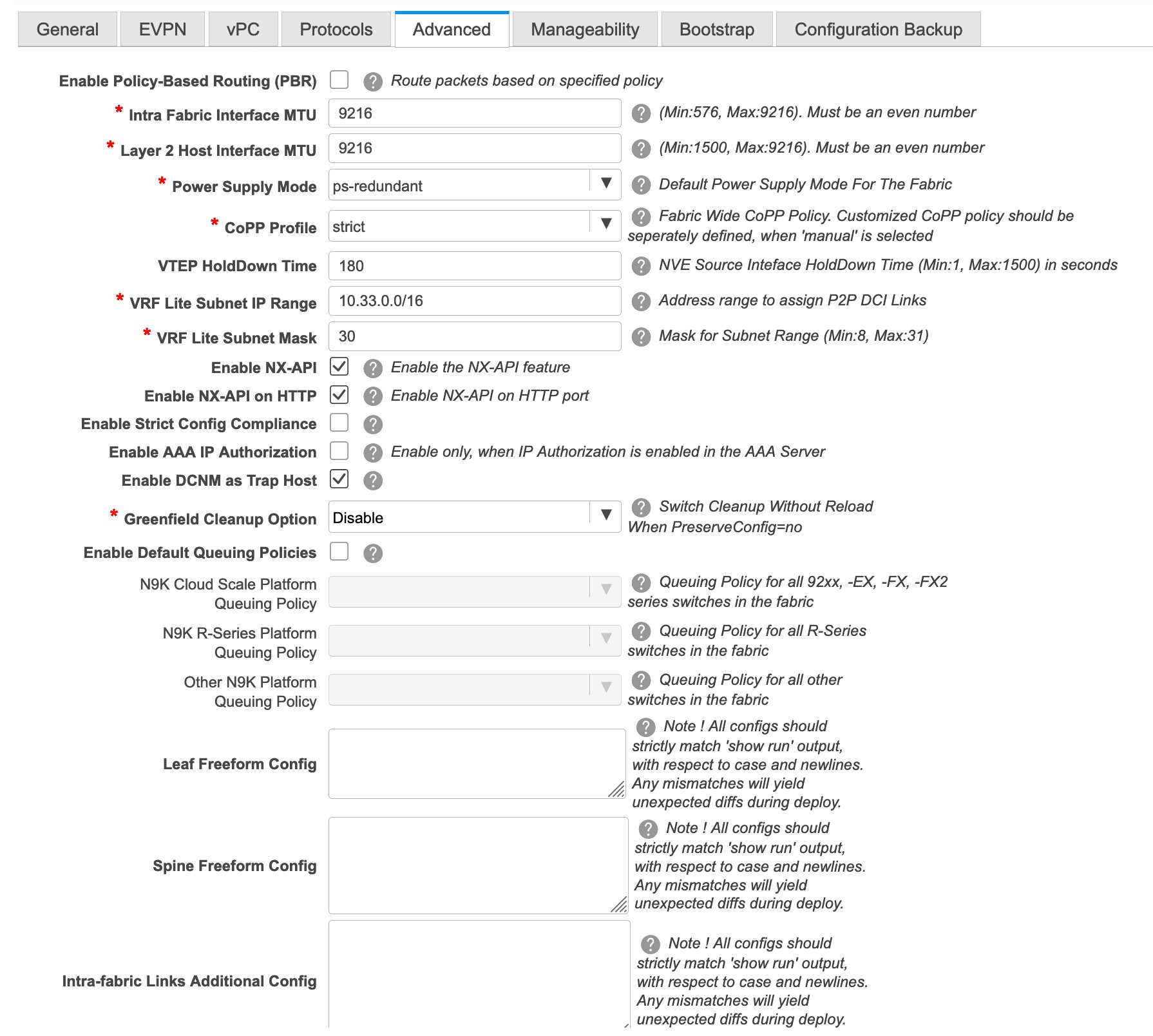
Enable Policy-Based Routing (PBR) - Select this check box to enable routing of packets based on the specified policy.
Intra Fabric Interface MTU - Specifies the MTU for the intra fabric interface. This value should be an even number.
Layer 2 Host Interface MTU - Specifies the MTU for the layer 2 host interface. This value should be an even number.
Power Supply Mode: Choose the appropriate power supply mode.
CoPP Profile: Choose the appropriate Control Plane Policing (CoPP) profile policy for the fabric. By default, the strict option is populated.
VTEP HoldDown Time - Specifies the NVE source interface hold down time.
VRF Lite Subnet IP Range and VRF Lite Subnet Mask – These fields are populated with the DCI subnet details. Update the fields as needed.
Enable NX-API - Specifies enabling of NX-API.
Enable NX-API on HTTP - Specifies enabling of NX-API on HTTP.
Enable Strict Config Compliance - Enable the Strict Config Compliance feature by selecting this check box. By default, this feature is disabled.
Enable AAA IP Authorization - Enables AAA IP authorization, when IP Authorization is enabled in the AAA Server
Enable DCNM as Trap Host - Select this check box to enable DCNM as a trap host.
Greenfield Cleanup Option: Enable or disable the switch cleanup option for greenfield switches.
Enable Default Queuing Policies: Check this check box to apply QoS policies on all the switches in this fabric. To remove the QoS policies that you applied on all the switches, uncheck this check box, update all the configurations to remove the references to the policies, and save and deploy. From Cisco DCNM Release 11.3(1), pre-defined QoS configurations are included that can be used for various Cisco Nexus 9000 Series Switches. When you check this check box, the appropriate QoS configurations are pushed to the switches in the fabric. The system queuing is updated when configurations are deployed to the switches. You can perform the interface marking with defined queuing policies, if required, by adding the required configuration to the per interface freeform block.
Review the actual queuing policies by opening the policy file in the template editor. From Cisco DCNM Web UI, choose Control > Template Library. Search for the queuing policies by the policy file name, for example, queuing_policy_default_8q_cloudscale. Choose the file and click the Modify/View template icon to edit the policy.
See the Cisco Nexus 9000 Series NX-OS Quality of Service Configuration Guide for platform specific details.
N9K Cloud Scale Platform Queuing Policy: Choose the queuing policy from the drop-down list to be applied to all Cisco Nexus 9200 Series Switches and the Cisco Nexus 9000 Series Switches that ends with EX, FX, and FX2 in the fabric. The valid values are queuing_policy_default_4q_cloudscale and queuing_policy_default_8q_cloudscale. Use the queuing_policy_default_4q_cloudscale policy for FEXes. You can change from the queuing_policy_default_4q_cloudscale policy to the queuing_policy_default_8q_cloudscale policy only when FEXes are offline.
N9K R-Series Platform Queuing Policy: Choose the queuing policy from the drop-down list to be applied to all Cisco Nexus switches that ends with R in the fabric. The valid value is queuing_policy_default_r_series.
Other N9K Platform Queuing Policy: Choose the queuing policy from the drop-down list to be applied to all other switches in the fabric other than the switches mentioned in the above two options. The valid value is queuing_policy_default_other.
Leaf Freeform Config: Add CLIs that should be added to switches that have the Leaf, Border, and Border Gateway roles.
Spine Freeform Config - Add CLIs that should be added to switches with a Spine, Border Spine, and Border Gateway Spine roles.
Intra-fabric Links Additional Config - Add CLIs that should be added to the intra-fabric links.
-
Click the Manageability tab.
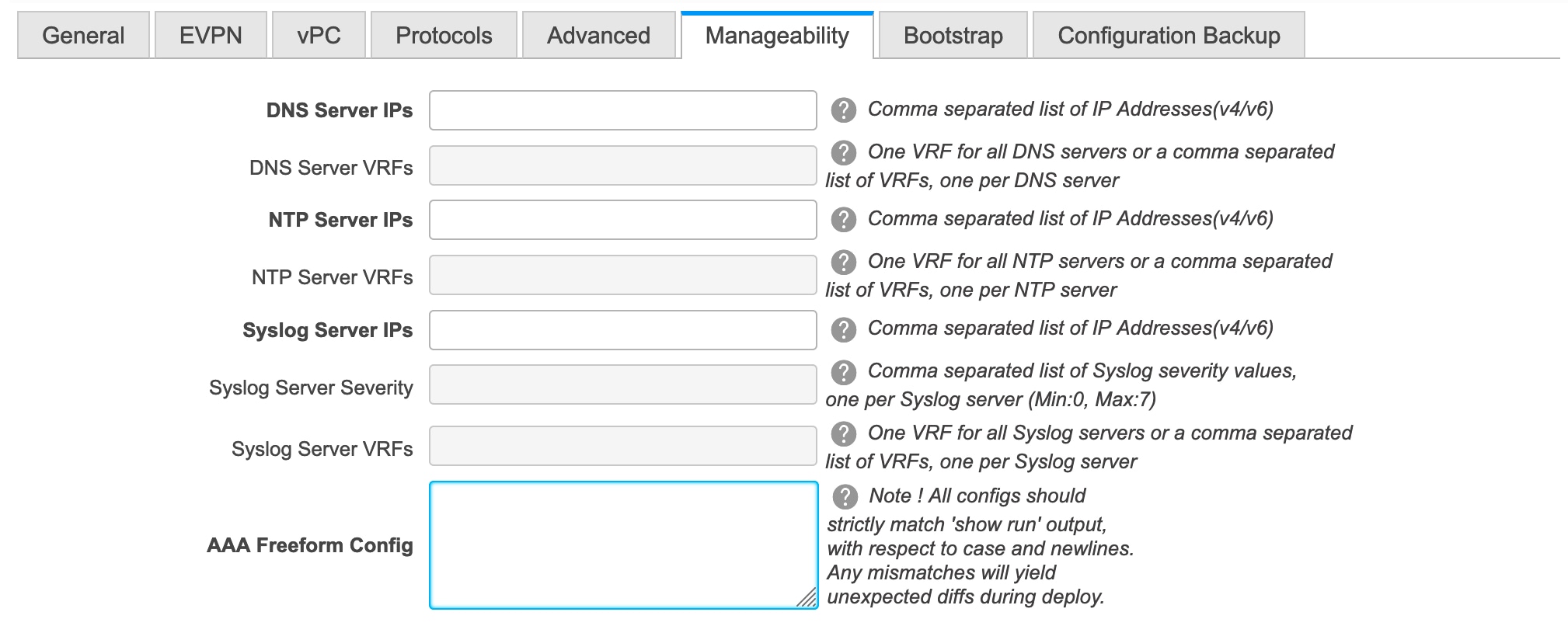
The fields in this tab are:
DNS Server IPs - Specifies the comma separated list of IP addresses (v4/v6) of the DNS servers.
DNS Server VRFs - Specifies one VRF for all DNS servers or a comma separated list of VRFs, one per DNS server.
NTP Server IPs - Specifies comma separated list of IP addresses (v4/v6) of the NTP server.
NTP Server VRFs - Specifies one VRF for all NTP servers or a comma separated list of VRFs, one per NTP server.
Syslog Server IPs – Specifies the comma separated list of IP addresses (v4/v6) IP address of the syslog servers, if used.
Syslog Server Severity – Specifies the comma separated list of syslog severity values, one per syslog server. The minimum value is 0 and the maximum value is 7. To specify a higher severity, enter a higher number.
Syslog Server VRFs – Specifies one VRF for all syslog servers or a comma separated list of VRFs, one per syslog server.
AAA Freeform Config – Specifies the AAA freeform configs.
If AAA configs are specified in the fabric settings, switch_freeform PTI with source as UNDERLAY_AAA and description as “AAA Configurations” will be created.
-
Click the Bootstrap tab.
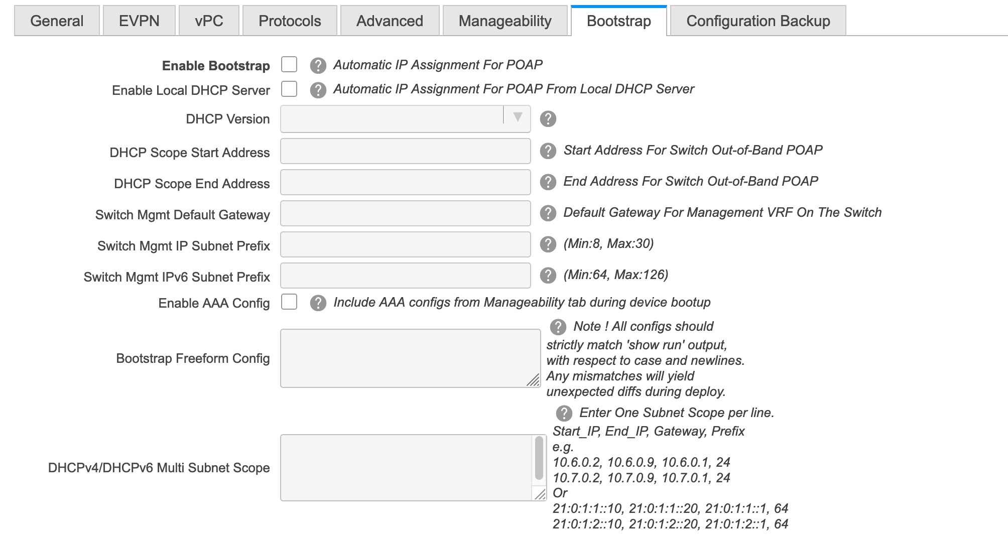
Enable Bootstrap - Select this check box to enable the bootstrap feature.
After you enable bootstrap, you can enable the DHCP server for automatic IP address assignment using one of the following methods:
-
External DHCP Server: Enter information about the external DHCP server in the Switch Mgmt Default Gateway and Switch Mgmt IP Subnet Prefix fields.
-
Local DHCP Server: Enable the Local DHCP Server checkbox and enter details for the remaining mandatory fields.
Enable Local DHCP Server - Select this check box to initiate enabling of automatic IP address assignment through the local DHCP server. When you select this check box, the DHCP Scope Start Address and DHCP Scope End Address fields become editable.
If you do not select this check box, DCNM uses the remote or external DHCP server for automatic IP address assignment.
DHCP Version – Select DHCPv4 or DHCPv6 from this drop-down list. When you select DHCPv4, the Switch Mgmt IPv6 Subnet Prefix field is disabled. If you select DHCPv6, the Switch Mgmt IP Subnet Prefix is disabled.
Note
Cisco DCNM IPv6 POAP is not supported with Cisco Nexus 7000 Series Switches. Cisco Nexus 9000 and 3000 Series Switches support IPv6 POAP only when switches are either L2 adjacent (eth1 or out-of-band subnet must be a /64) or they are L3 adjacent residing in some IPv6 /64 subnet. Subnet prefixes other than /64 are not supported.
DHCP Scope Start Address and DHCP Scope End Address - Specifies the first and last IP addresses of the IP address range to be used for the switch out of band POAP.
Switch Mgmt Default Gateway - Specifies the default gateway for the management VRF on the switch.
Switch Mgmt IP Subnet Prefix - Specifies the prefix for the Mgmt0 interface on the switch. The prefix should be between 8 and 30.
DHCP scope and management default gateway IP address specification - If you specify the management default gateway IP address 10.0.1.0 and subnet mask 24, ensure that the DHCP scope is within the specified subnet, between 10.0.1.1 and 10.0.1.254.
Switch Mgmt IPv6 Subnet Prefix - Specifies the IPv6 prefix for the Mgmt0 interface on the switch. The prefix should be between 112 and 126. This field is editable if you enable IPv6 for DHCP.
Enable AAA Config – Select this check box to include AAA configs from the Manageability tab during device bootup.
Bootstrap Freeform Config - (Optional) Enter additional commands as needed. For example, if you are using AAA or remote authentication related configurations, you need to add these configurations in this field to save the intent. After the devices boot up, they contain the intent defined in the Bootstrap Freeform Config field.
Copy-paste the running-config to a freeform config field with correct indentation, as seen in the running configuration on the NX-OS switches. The freeform config must match the running config. For more information, see Resolving Freeform Config Errors in Switches.
DHCPv4/DHCPv6 Multi Subnet Scope - Specifies the field to enter one subnet scope per line. This field is editable after you check the Enable Local DHCP Server check box.
The format of the scope should be defined as:
DHCP Scope Start Address, DHCP Scope End Address, Switch Management Default Gateway, Switch Management Subnet Prefix
For example: 10.6.0.2, 10.6.0.9, 10.6.0.1, 24
-
-
Click the Configuration Backup tab. The fields on this tab are:
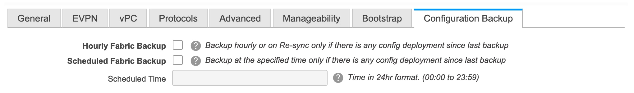
Hourly Fabric Backup: Select the check box to enable an hourly backup of fabric configurations and the intent.
You can enable an hourly backup for fresh fabric configurations and the intent as well. If there is a configuration push in the previous hour, DCNM takes a backup.
Intent refers to configurations that are saved in DCNM but yet to be provisioned on the switches.
Scheduled Fabric Backup: Check the check box to enable a daily backup. This backup tracks changes in running configurations on the fabric devices that are not tracked by configuration compliance.
Scheduled Time: Specify the scheduled backup time in a 24-hour format. This field is enabled if you check the Scheduled Fabric Backup check box.
Select both the check boxes to enable both back up processes.
The backup process is initiated after you click Save.
Note
Hourly and scheduled backup processes happen only during the next periodic configuration compliance activity, and there can be a delay of up to an hour. To trigger an immediate backup, do the following:
-
Choose Control > Fabric Builder. The Fabric Builder screen comes up.
-
Click within the specific fabric box. The fabric topology screen comes up.
-
From the Actions panel at the left part of the screen, click Re-Sync Fabric.
You can also initiate the fabric backup in the fabric topology window. Click Backup Now in the Actions pane.
-
-
Click Save after filling and updating relevant information. A note appears briefly at the bottom right part of the screen, indicating that the fabric is created. When a fabric is created, the fabric page comes up. The fabric name appears at the top left part of the screen.
(At the same time, the newly created fabric instance appears on the Fabric Builder screen. To go to the Fabric Builder screen, click the left arrow (←) button above the Actions panel [to the left of the screen]).
The Actions panel at the left part of the screen allows you to perform various functions. One of them is the Add switches option to add switches to the fabric. After you create a fabric, you should add fabric devices. The options are explained:
-
Tabular View - By default, the switches are displayed in the topology view. Use this option to view switches in the tabular view.
-
Refresh topology - Allows you to refresh the topology.
-
Save Layout – Saves a custom view of the topology. You can create a specific view in the topology and save it for ease of use.
-
Delete saved layout – Deletes the custom view of the topology
-
Topology views - You can choose between Hierarchical, Random and Custom saved layout display options.
-
Hierarchical - Provides an architectural view of your topology. Various Switch Roles can be defined that draws the nodes on how you configure your CLOS topology.
-
Random - Nodes are placed randomly on the screen. DCNM tries to make a guess and intelligently place nodes that belong together in close proximity.
-
Custom saved layout - You can drag nodes around to your liking. Once you have the positions as how you like, you can click Save Layout to remember the positions. Next time you come to the topology, DCNM will draw the nodes based on your last saved layout positions.
-
-
Restore Fabric – Allows you to restore the fabric to a prior DCNM configuration state (one month back, two months back, and so on). For more information, see Restore Fabric section.
-
Backup Now: You can initiate a fabric backup manually by clicking Backup Now. Enter a name for the tag and click OK. Regardless of the settings you choose under the Configuration Backup tab in the Fabric Settings dialog box, you can initiate a backup using this option.
-
Resync Fabric - Use this option to resynchronize DCNM state when there is a large scale out-of-band change, or if configuration changes do not register in the DCNM properly. The resync operation does a full CC run for the fabric switches and recollects “show run” and “show run all” commands from the switches. When you initiate the re-sync process, a progress message is displayed on the screen. During the re-sync, the running configuration is taken from the switches. Then, the OUT-OF-SYNC/IN-SYNC status for the switch is recalculated based on the intent or expected configuration defined in DCNM versus the current running configuration that was taken from the switches.
-
Add Switches – Allows you to add switch instances to the fabric.
-
Fabric Settings – Allows you to view or edit fabric settings.
-
Cloud icon - Click the Cloud icon to display (or not display) an Undiscovered cloud.
When you click the icon, the Undiscovered cloud and its links to the selected fabric topology are not displayed.
Click the Cloud icon again to display the Undiscovered cloud.
-
SCOPE - You can toggle between fabrics by using the SCOPE drop-down box at the top right part of the screen. The current fabric is highlighted. An MSD and its member fabrics are distinctly displayed, wherein the member fabrics are indented, under the MSD fabric.
VXLAN Fabric With eBGP Underlay – Pointers
-
The supported roles are leaf, spine, and border leaf.
-
On the border device, VRF-Lite is supported with manual mode. There is no Multi-Site support for external connectivity.
-
TRM is supported.
-
You must apply policies on the leaf and spine switches for a functional fabric.
-
When you convert a non-VXLAN (or routed fabric) to a VXLAN enabled fabric, you can create and deploy overlay networks and VRFs.
Applying Policies On A Fabric With An eBGP Underlay
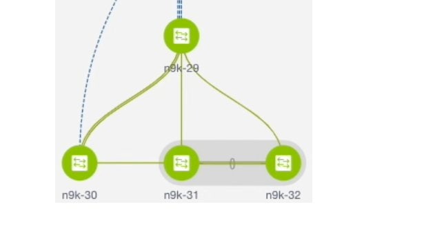
The topology shows a VXLAN fabric enabled with eBGP for the underlay. In DCNM, a fabric with the Easy_Fabric_eBGP template is created. One spine switch (n9k-29) and three leaf switches (n9k-30, and vPC switch pair n9k-31 and n9k-32) are imported to it.
This topic covers the following:
-
Creating a Multi-AS mode fabric: This section mainly covers Multi-AS mode fabric creation. In a Multi-AS mode fabric, spine switches have a common BGP AS number and each leaf switch has a unique BGP AS number. Use the same steps for Dual-AS to Multi-AS mode fabric conversion.
-
Creating a Dual-AS mode fabric: Alternate steps are mentioned for Dual-AS mode fabric creation. Use the same steps for Multi-AS to a Dual-AS mode fabric conversion.
In a Dual-AS fabric, all spine switches have a common BGP AS number and all leaf switches have a common BGP AS number (differing from the spine switches’ BGP AS number). You must deploy policies as explained in the next section.
Deploying Fabric Underlay Policies
You must manually add the leaf_bgp_asn policy on each leaf switch to specify the BGP AS number used on the switch. Implementing the Save & Deploy operation afterward will generate eBGP peering over the physical interface between the leaf and spine switches to exchange underlay reachability information.
-
Click Tabular View at the left part of the screen. The Switches | Links screen comes up.
-
Select the leaf switch (n9k-30 check box for example) and click View/Edit Policies. The View/Edit Policies screen comes up.
Note
When you create an eBGP fabric in the Dual-AS mode (or change from the Multi-AS mode to Dual-AS mode), select all leaf switches since they have a common BGP AS number.
-
Click Add. The Add Policy screen comes up.
-
From the Policy drop down box, select leaf_bgp_asn and enter the BGP AS number in the BGP AS # field.
-
Click Save.
-
Repeat the procedure for the vPC switches. For a vPC switch pair, select both switches and apply the bgp_asn policy.
Note
This step is not needed if you create a fabric in the Dual-AS mode (or converting to the Dual-AS mode), and you have assigned a BGP AS number to all of them, as explained in the earlier steps.
-
Close the screen.
-
In the topology screen, click Save & Deploy at the top right part of the screen.
-
Deploy configurations as per the Config Deployment wizard.
Deploying Fabric Overlay Policies
You must manually add the eBGP overlay policy for overlay peering. DCNM provides the eBGP leaf and spine overlay peering policy templates that you can manually add to the leaf and spine switches to form the EVPN overlay peering.
Deploying Spine Switch Overlay Policies
Add the ebgp_overlay_spine_all_neighbor policy on the spine switch n9k-29.
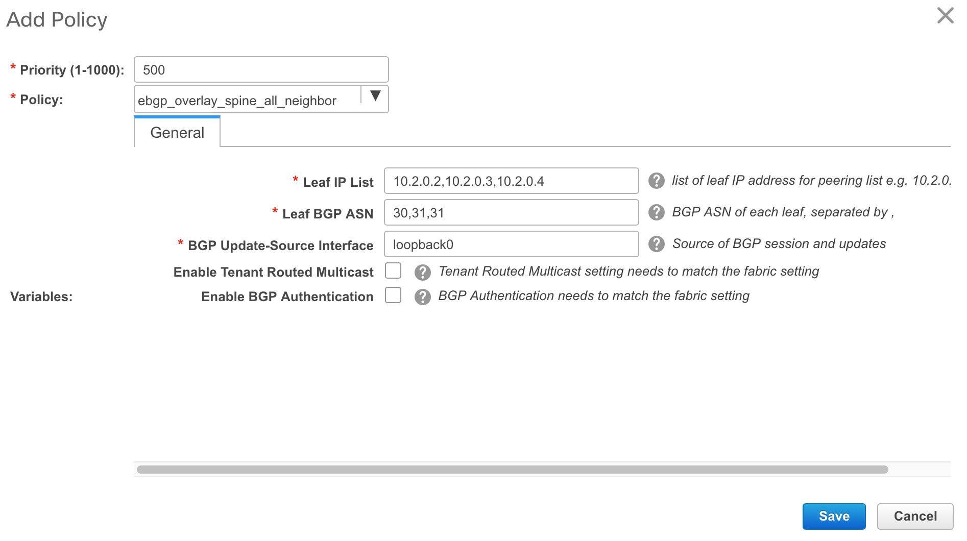
The fields on the screen are:
Leaf IP List - IP addresses of the connected leaf switch routing loopback interfaces.
10.2.0.2 is the loopback 0 peering IP address of leaf switch n9k-30. 10.2.0.3 and 10.2.0.4 are the IP addresses of the vPC switch pair n9k-31 and n9k-32.
Leaf BGP ASN – The BGP AS numbers of the leaf switches. Note that the AS number of vPC switches is the same, 31.
Note |
When you create fabric in the Dual-AS mode, (or convert to Dual-AS mode), you must update this field with the common BGP AS number all the leaf switches belong to. |
BGP Update-Source Interface – This is the source interface of the BGP update. You can use loopback0 for this field.
Enable Tenant Routed Multicast – Select the checkbox to enable TRM for handling overlay multicast traffic. TRM enabling must match the fabric setting.
Enable BGP Authentication – Select the checkbox to enable BGP authentication.
The BGP authentication must match the fabric setting. Refer the Retrieving the Authentication Key section to know more about BGP authentication.
Deploying Leaf Switch Overlay Policies
Add the ebgp_overlay_leaf_all_neighbor policy on all the leaf switches, to establish eBGP overlay peering towards the spine switch.

The fields on the screen are:
Spine IP List – IP addresses of the spine switch routing loopback interfaces.
10.2.0.1 is the loopback 0 peering IP address of spine switch n9k-29.
BGP Update-Source Interface – This is the source interface of the BGP update. You can use loopback0 for this field.
Enable Tenant Routed Multicast – Select the checkbox to enable TRM for handling overlay multicast traffic. TRM enabling must match the fabric setting.
Enable BGP Authentication – Select the checkbox to enable BGP authentication.
The BGP authentication must match the fabric setting. Refer the Retrieving the Authentication Key section to know more about BGP authentication.
Click Save & Deploy at the top right part of the screen, and deploy configurations as per the Config Deployment wizard. Or, use the View/Edit Policy option to select the policy and click Push Config to deploy the configuration.
Dual-AS Fabric Deployment
In a Dual-AS fabric, the spine switches have a unique BGP AS number and the leaf switches have a unique AS number.
-
Deploy the spine overlay policy as explained in the Multi-AS fabric section.
-
Deploy the leaf overlay and underlay policies on all leaf switches at once, since they have a common AS number.
Additional Pointers
-
Brownfield migration is not supported for eBGP fabric.
-
You cannot change the leaf switch AS number after it is created and the Save & Deploy operation is executed. You need to delete the leaf_bgp_asn policy and execute the Save & Deploy operation to remove BGP configuration related to this AS first. Then, you can add the leaf_bgp_asn policy with the new AS number.
-
If you want to switch between Multi-AS and Dual-AS modes, remove all manually added BGP policies (including leaf_bgp_asn on the leaf switch and the ebgp overlay policies), and execute the Save & Deploy operation before the mode change.
-
You cannot change or delete the leaf switch leaf_bgp_asn policy if there are ebgp overlay policies present on the device. You need to delete the ebgp overlay policy first, and then delete the leaf_bgp_asn policy.
Overview of Networks in a Routed Fabric
From Cisco DCNM Release 11.3(1), you can create a top-down network configuration for a routed fabric using DCNM. A routed fabric is run in one VRF, which is the default VRF. Note that creating VRFs manually is disabled for a routed fabric. Since the fabric is an IPv4 fabric, IPv6 address within the network is not supported. In a routed fabric, a network can only be attached to one device or a pair of vPC devices, unless it is a Layer 2 only network.
Note |
A routed fabric network configuration will not be put under a config-profile. |
When the eBGP fabric is configured as Routed Fabric (EVPN is disabled), at the fabric level, you can select the first hop redundancy protocol (FHRP) for host traffic to be either HSRP or VRRP. HSRP is the default value.
For a vPC pair, DCNM generates network level HSRP or VRRP configuration based on the fabric setting. If HSRP is chosen, each network is configured with one HSRP group, and the HSRP VIP address. By default, all the networks will share the same HSRP group number allocated by DCNM, while you can overwrite it per network. VRRP support is similar to HSRP.
Guidelines
-
HSRP authentication or VRRP authentication is not supported. If you want to use authentication, you can enter the applicable commands in the network freeform config.
-
vPC peer gateway can be used to minimize peer link usage in the case that some third-party devices ignore the HSRP virtual-MAC and use the ARP packet source MAC for ARP learning. In Routed fabric mode, DCNM generates vPC peer gateway command for VPC devices.
-
For an eBGP fabric, changing between routed fabric type and EVPN fabric type, or HSRP and VRRP, is not allowed with the presence of networks and VRFs. You need to undeploy and delete these networks and VRFs before changing the fabric type or FHRP. For more information, see Undeploying Networks for the Standalone Fabric and Undeploying VRFs for the Standalone Fabric.
-
After the upgrade from DCNM Release 11.2(1) to 11.3(1), if the fabric was running in Routed Fabric mode previously, the default fabric values such as FHRP protocol and network VLAN range are internally set for a Routed Fabric. You need to edit the fabric settings if you want to configure different values.
-
Before deploying a network configuration, you need to update the FHRP protocol fabric setting and click Save & Deploy.
Creating and Deploying a Network in a Routed Fabric
Before you begin
Procedure
| Step 1 |
Navigate to Control > Networks. |
||||
| Step 2 |
From the SCOPE drop-down list, choose a routed fabric. |
||||
| Step 3 |
Click the Add button in the Networks window to create a network. 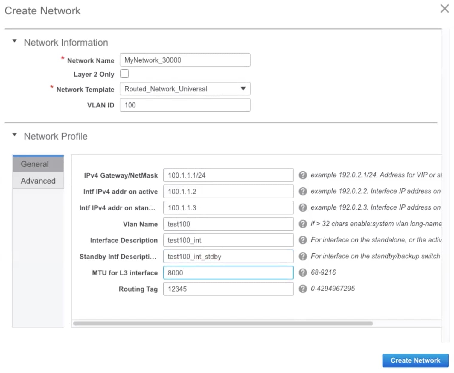 Network Name: Specifies the name of the network. The network name should not contain any white spaces or special characters except underscore (_) and hyphen (-). Layer 2 Only: Optional. Specifies whether the network is a Layer 2 only network. FHRP configuration is not generated in a Layer 2 only network.
Network Template: Select the Routed_Network_Universal template. VLAN ID: Optional. Specifies the corresponding tenant VLAN ID for the network. Network Profile section contains the General and Advanced tabs. General tab IPv4 Gateway/NetMask: Specifies the IPv4 gateway address with subnet. Intf IPv4 addr on active: Specifies the IPv4 interface address on an active/master device in a vPC pair. This field is applicable only when you are creating and deploying a network for a vPC pair of devices. Intf IPv4 addr on standby: Specifies the IPv4 interface address on a standby/backup device in a vPC pair. This field is applicable only when you are creating and deploying a network for a vPC pair of devices.
The following fields under the General tab are optional: Vlan Name: Specifies the VLAN name. Interface Description: Specifies the description for the interface. Standby Intf Description: Specifies the description for the standby interface in a vPC pair. MTU for the L3 interface: Enter the MTU for Layer 3 interfaces. Routing Tag: Specifies the routing tag that is associated with each gateway IP address prefix. Advanced tab: This tab is applicable only when you are creating and deploying a network for a vPC pair of devices. 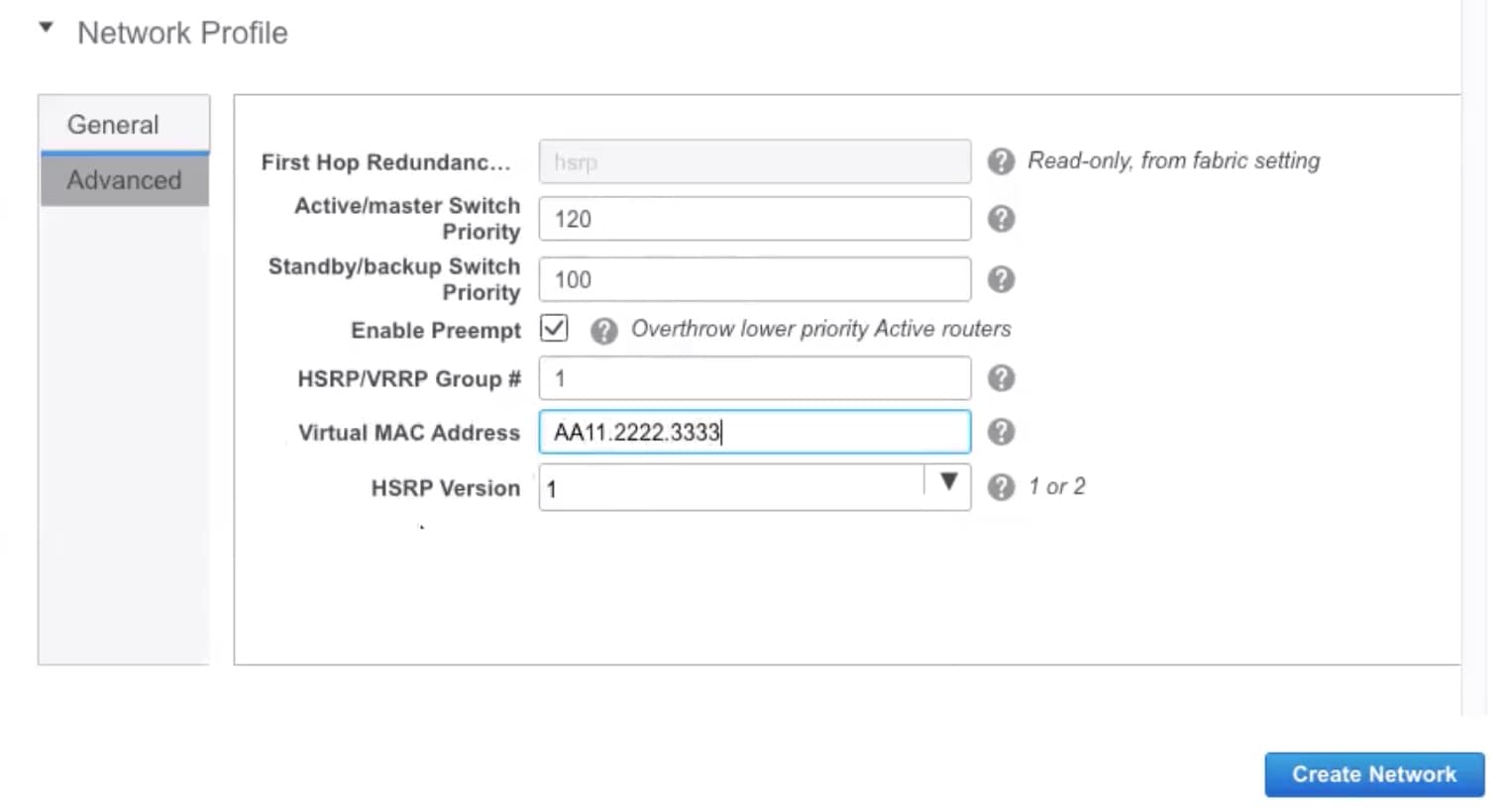 First Hop Redundancy Protocol: A read-only field that specifies FHRP selected in the fabric settings. Active/master Switch Priority:Specifies the priority of the active or master device. Standby/backup Switch Priority: Specifies the priority of the standby or backup device. The default value is 100. Note that this default value is not displayed when you preview the network configuration before deployment. Enable Preempt: Specifies whether the standby/backup device can preempt a active or master device. HSRP/VRRP Group #: Specifies the HSRP or VRRP group number. By default, HSRP group number is 1. Virtual MAC Address: Optional. Specifies the virtual MAC address. By default, VMAC is internally generated based on the HSRP group number (0000.0c9f.f000 + group number). The virtual MAC address is only applicable when hsrp is selected in the fabric settings. HSRP Version: Specifies the HSRP version. The default value is 1. The HSRP version field is only applicable for HSRP. |
||||
| Step 4 |
Click Create Network. |
||||
| Step 5 |
In the Networks window, select the check box next to a network and click Continue.
|
||||
| Step 6 |
Select a device or a vPC pair to deploy a network.
|
||||
| Step 7 |
In the Network Attachment window, for a vPC pair, assign the active state for a device. Enter true under the isActive column for an active device and false for a standby device. Click Save. 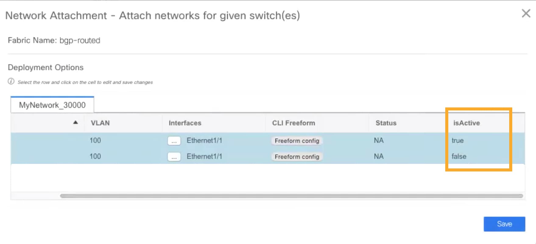 |
||||
| Step 8 |
(Optional) Click the Preview icon to preview the configs that will be deployed on devices. The Preview Configuration window is displayed. 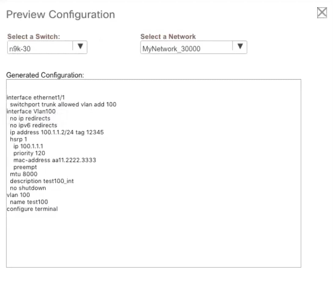 |
||||
| Step 9 |
Click the Deploy button in the Network / VRF Deployment window. You can also deploy the network by navigating to the Fabric Builder window and clicking the Deploy button. |
Creating Inter-Fabric Links Between a Routed Fabric and an External Fabric
From DCNM Release 11.3(1), you can use an inter-fabric link to connect a route fabric to an edge router. This link configures an IP address on the physical interface and establish eBGP peering with the edge router on default vrf. The BGP configuration includes advertising default route to leaf switches.
Note |
The Fabric Monitor Mode check box in the external fabric settings can be unchecked. Unchecking the Fabric Monitor Mode check box enables DCNM to deploy configurations to the external fabric. For more information, see Creating an External Fabric. |
Procedure
| Step 1 |
Navigate to Control > Fabric Builder. |
||
| Step 2 |
Click a routed a fabric in the Fabric Builder window. |
||
| Step 3 |
Click Tabular view in the Actions panel that is displayed at the left part of the window. |
||
| Step 4 |
Click the Links tab. |
||
| Step 5 |
Click the Add icon to add a link. The Link Management – Add Link window is displayed. 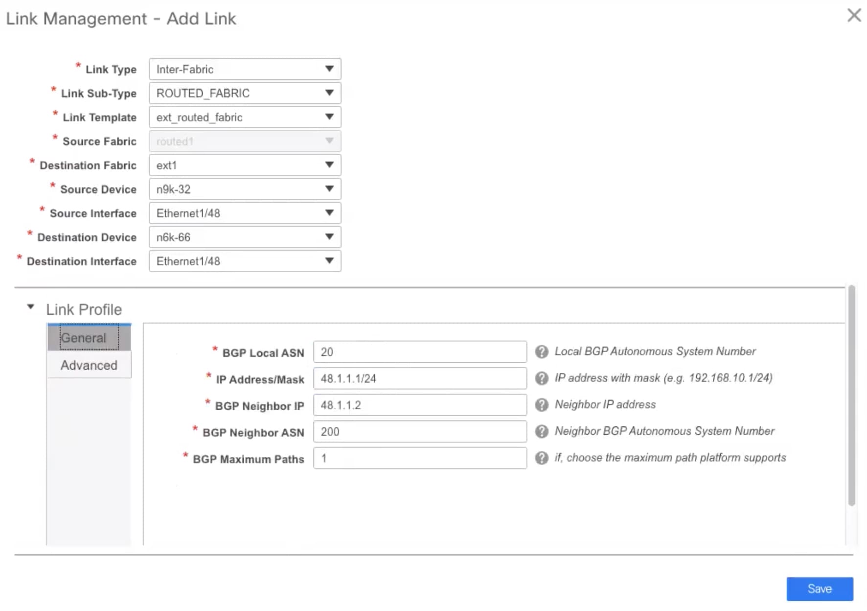 Link Type – Choose Inter-Fabric to create an inter-fabric connection between two fabrics, via their border switches or edge routers. Link Sub-Type – This field populates the IFC type. Choose ROUTED_FABRIC from the drop-down list. Link Template: The link template is populated. The templates are autopopulated with corresponding pre-packaged default templates that are based on your selection. For a routed fabric, the ext_routed_fabric template is populated. Source Fabric - This field is prepopulated with the source fabric name. Destination Fabric - Choose the destination fabric from this drop-down box. Source Device and Source Interface - Choose the source device and Ethernet or port channel interface that connects to the destination device. Destination Device and Destination Interface—Choose the destination device and Ethernet or port channel interface that connects to the source device. Based on the selection of the source device and source interface, the destination information is autopopulated based on Cisco Discovery Protocol information, if available. There is an extra validation performed to ensure that the destination external device is indeed part of the destination fabric. General tab in the Link Profile section. BGP Local ASN: In this field, the AS number of the leaf is autopopulated if you have created and applied the leaf_bgp_asn policy. IP Address/Mask: Fill up this field with the IP address of the source interface that connects to the destination device. BGP Neighbor IP: Fill up this field with the IP address of the destination interface. BGP Neighbor ASN: In this field, the AS number of the destination device is autopopulated. BGP Maximum Paths: Specifies the maximum supported BGP paths. The Advanced tab contains the following optional fields: Source Interface Description and Destination Interface Description – Describe the links for later use. After Save & Deploy, this description will reflect in the running configuration. Source Interface Freeform CLIs and Destination Interface Freeform CLIs: Enter the freeform configurations specific to the source and destination interfaces. You should add the configurations as displayed in the running configuration of the switch, without indentation. See Freeform Configurations on Fabric Switches section for a detailed explanation and examples. |
||
| Step 6 |
Click Save to finish adding a link. |
||
| Step 7 |
Click the Back icon to navigate back to the Fabric Builder window. |
||
| Step 8 |
Right-click the device which is connecting to the edge router in the external fabric, and select Deploy Config. |
||
| Step 9 |
In the Config Deployment window, click Deploy Config. |
||
| Step 10 |
Navigate to the external fabric in the Fabric Builder window, and click Tabular view in the Actions panel. Click the Links tab to see all the links for the external fabric. You can see the inter-fabric link that has been created.
|
||
| Step 11 |
Click the Back icon twice to navigate back to the Fabric Builder window. |
||
| Step 12 |
Click the external fabric connecting to the routed fabric. |
||
| Step 13 |
Right-click the device which is connecting to the routed fabric, and select Deploy Config. |
||
| Step 14 |
In the Config Deployment window, click Deploy Config. |
Creating an External Fabric
In DCNM 11.1(1) release, you can add switches to the external fabric. Generic pointers:
-
An external fabric is a monitor-only or managed mode fabric.
-
You can import, remove, and delete switches for an external fabric.
-
For Inter-Fabric Connection (IFC) cases, you can choose Cisco 9000, 7000 and 5600 Series switches as destination switches in the external fabric.
-
You can use non-existing switches as destination switches.
-
The template that supports an external fabric is External_Fabric.
-
If an external fabric is an MSD fabric member, then the MSD topology screen displays the external fabric with its devices, along with the member fabrics and their devices.
When viewed from an external fabric topology screen, any connections to non-DCNM managed switches are represented by a cloud icon labelled as Undiscovered.
-
You can set up a Multi-Site or a VRF-lite IFC by manually configuring the links for the border devices in the VXLAN fabric or by using an automatic Deploy Border Gateway Method or VRF Lite IFC Deploy Method. If you are configuring the links manually for the border devices, we recommend using the Core Router role to set up a multisite eBGP underlay from a Border Gateway device to a Core Router and the Edge Router role to set up a VRF-lite Inter-Fabric Connection (IFC) from a Border device to an Edge device.
-
You can discover the following non-Nexus devices in an external fabric:
-
IOS-XE family devices: Cisco CSR 1000v, Cisco IOS XE Gibraltar 16.10.x
-
IOS-XR family devices: ASR 9000 Series Routers, IOS XR Release 6.5.2 and Cisco NCS 5500 Series Routers, IOS XR Release 6.5.3
-
Arista 4.2 (Any model)
-
-
Configure all the non-Nexus devices, except Cisco CSR 1000v, before adding them to the external fabric.
-
You can connect a Cisco data center to a public cloud using Cisco CSR 1000v. See the Connecting Cisco Data Center and a Public Cloud chapter for a use case.
Creating External Fabric from Fabric Builder
Follow these steps to create an external fabric from Fabric Builder.
-
Click Control > Fabric Builder. The Fabric Builder page comes up.
-
Click the Create Fabric button. The Add Fabric screen comes up. The fields in this screen are:
Fabric Name - Enter the name of the external fabric.
Fabric Template - Choose External_Fabric.
When you choose the fabric template, the fabric creation screen for creating an external fabric comes up.
-
Fill up the General, Advanced, Resources and DCI tabs as shown below.
General tab
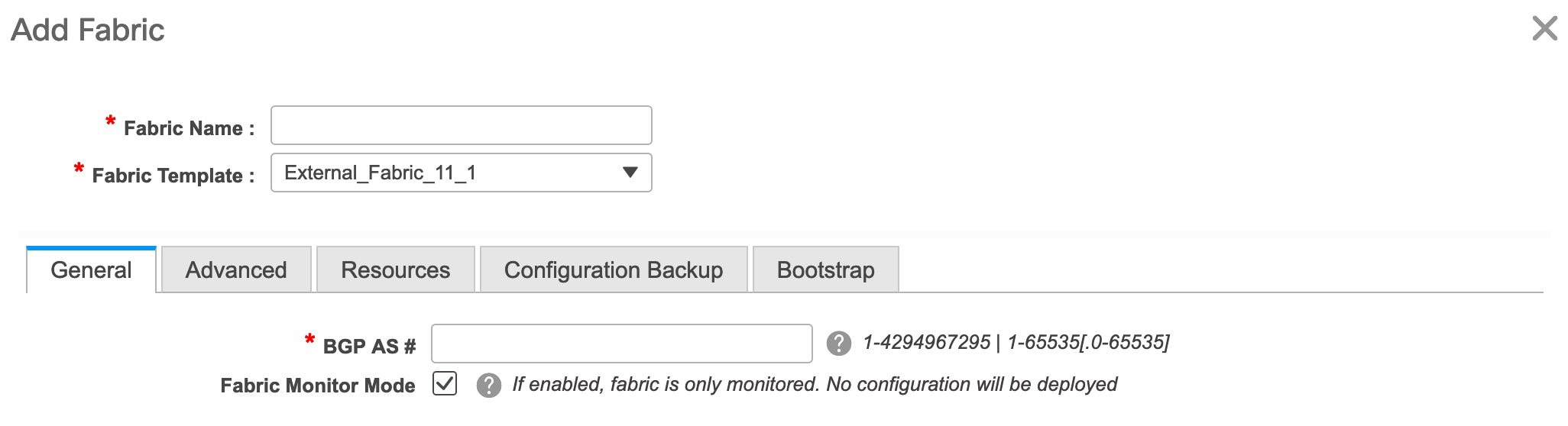
BGP AS # - Enter the BGP AS number.
Fabric Monitor Mode – Clear the checkbox if you want DCNM to manage the fabric. Keep the checkbox selected to enable a monitor only external fabric.
When you create an Inter-Fabric Connection from a VXLAN fabric to this external fabric, the BGP AS number is referenced as the external or neighbor fabric AS Number.
When an external fabric is set to Fabric Monitor Mode Only, you cannot deploy configurations on its switches. If you click Save & Deploy in the fabric topology screen, it displays an error message.
The configurations must be pushed for non-Nexus devices before you discover them in the fabric. You cannot push configurations in the monitor mode.
However, the following settings (available when you right-click the switch icon) are allowed:
Advanced tab
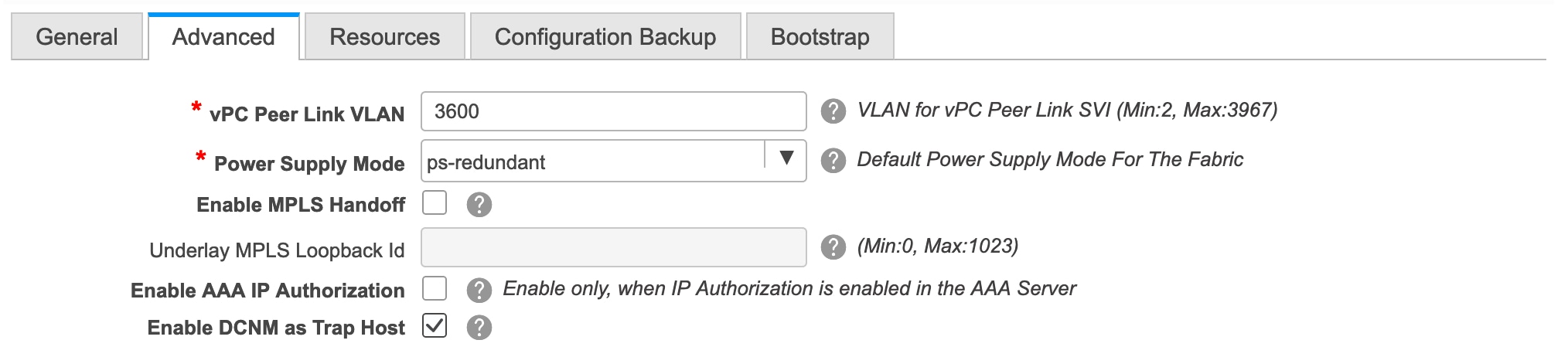
vPC Peer Link VLAN - The vPC peer link VLAN ID is autopopulated. Update the field to reflect the correct value.
Power Supply Mode - Choose the appropriate power supply mode.
Enable MPLS Handoff: Select the check box to enable the MPLS Handoff feature. For more information, see Border Provisioning Use Case in VXLAN BGP EVPN Fabrics - MPLS SR and LDP Handoff.
Underlay MPLS Loopback Id: Specifies the underlay MPLS loopback ID. The default value is 101.
Resources tab
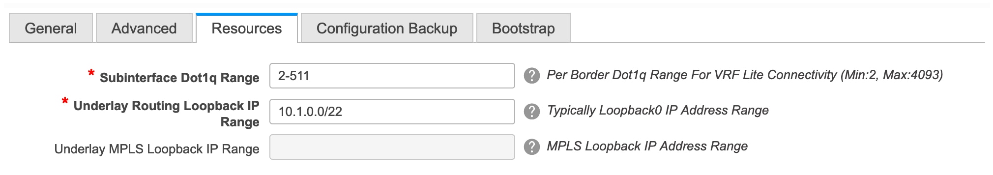
Subinterface Dot1q Range - The subinterface 802.1Q range and the underlay routing loopback IP address range are autopopulated.
Underlay Routing Loopback IP Range - Specifies loopback IP addresses for the protocol peering.
Underlay MPLS Loopback IP Range: Specifies the underlay MPLS SR or LDP loopback IP address range.
Note that the IP range should be unique, that is, it should not overlap with IP ranges of the other fabrics.
Enable AAA IP Authorization - Enables AAA IP authorization, when IP Authorization is enabled in the AAA Server
Enable DCNM as Trap Host - Select this check box to enable DCNM as a trap host.
-
Click the Configuration Backup tab.
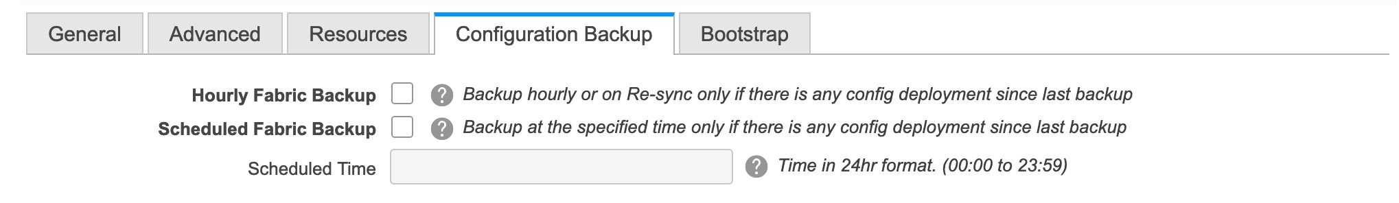
The fields on this tab are:
Hourly Fabric Backup: Select the check box to enable an hourly backup of fabric configurations and the intent.
You can enable an hourly backup for fresh fabric configurations and the intent as well. If there is a configuration push in the previous hour, DCNM takes a backup. In case of the external fabric, the entire configuration on the switch is not converted to intent on DCNM as compared to the VXLAN fabric. Therefore, for the external fabric, both intent and running configuration are backed up.
Intent refers to configurations that are saved in DCNM but yet to be provisioned on the switches.
Scheduled Fabric Backup: Check the check box to enable a daily backup. This backup tracks changes in running configurations on the fabric devices that are not tracked by configuration compliance.
Scheduled Time: Specify the scheduled backup time in a 24-hour format. This field is enabled if you check the Scheduled Fabric Backup check box.
Select both the check boxes to enable both back up processes.
The backup process is initiated after you click Save.
You can also initiate the fabric backup in the fabric topology window. Click Backup Now in the Actions pane.
Pointers for hourly and scheduled backup:
-
The backups contain running configuration and intent pushed by DCNM. Configuration compliance forces the running config to be the same as the DCNM config. Note that for the external fabric, only some configurations are part of intent and the remaining configurations are not tracked by DCNM. Therefore, as part of backup, both DCNM intent and running config from switch are captured.
-
The backups happen only during the next periodic configuration compliance activity, and there can be a delay of up to an hour.
-
If you encounter an error during a device backup in a fabric, the backup for the entire fabric fails.
-
-
Click the Bootstrap tab.
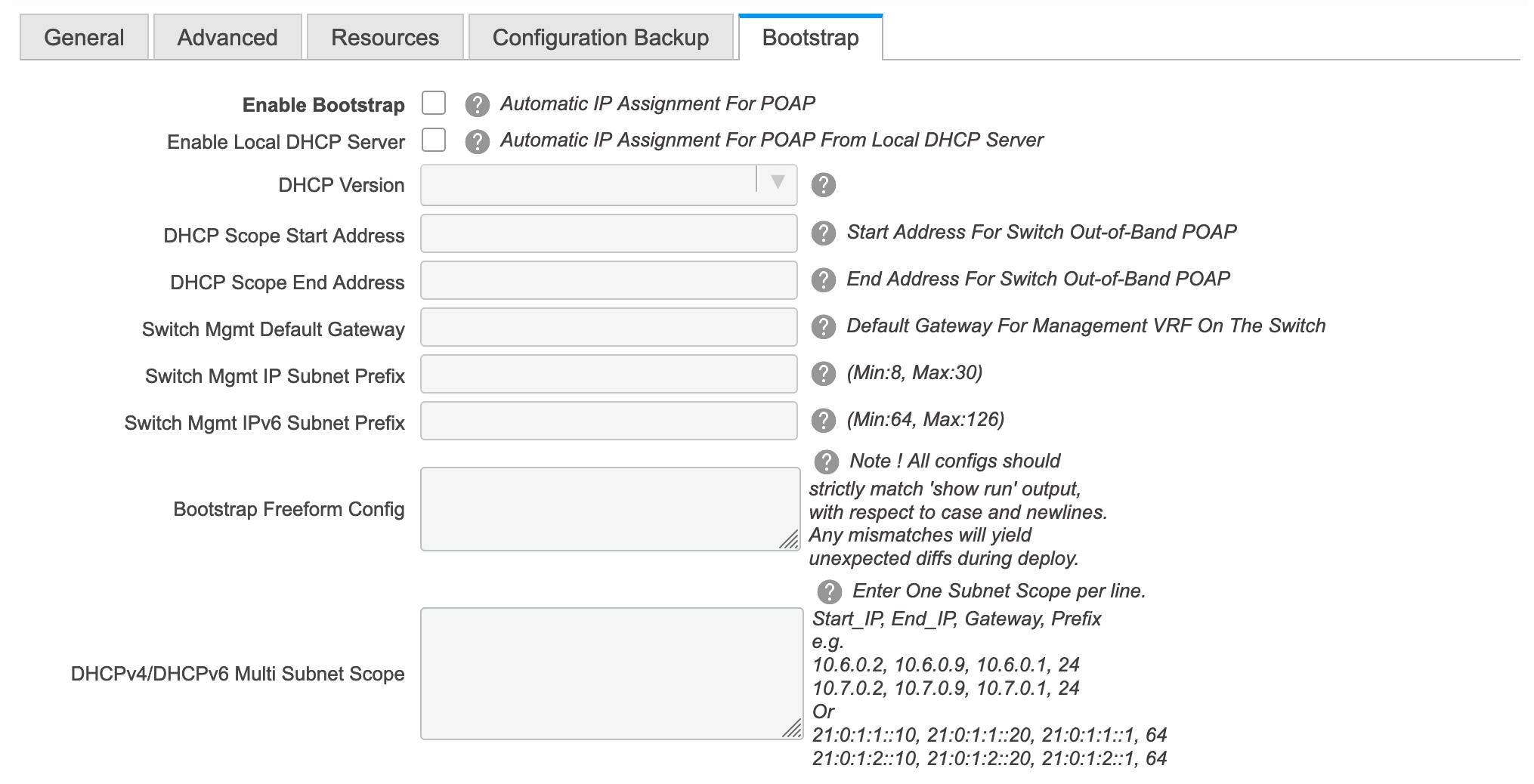
Enable Bootstrap - Select this check box to enable the bootstrap feature.
After you enable bootstrap, you can enable the DHCP server for automatic IP address assignment using one of the following methods:
-
External DHCP Server: Enter information about the external DHCP server in the Switch Mgmt Default Gateway and Switch Mgmt IP Subnet Prefix fields.
-
Local DHCP Server: Enable the Local DHCP Server checkbox and enter details for the remaining mandatory fields.
Enable Local DHCP Server - Select this check box to initiate enabling of automatic IP address assignment through the local DHCP server. When you select this check box, all the remaining fields become editable.
DHCP Version – Select DHCPv4 or DHCPv6 from this drop-down list. When you select DHCPv4, the Switch Mgmt IPv6 Subnet Prefix field is disabled. If you select DHCPv6, the Switch Mgmt IP Subnet Prefix is disabled.
Note
Cisco DCNM IPv6 POAP is not supported with Cisco Nexus 7000 Series Switches. Cisco Nexus 9000 and 3000 Series Switches support IPv6 POAP only when switches are either L2 adjacent (eth1 or out-of-band subnet must be a /64) or they are L3 adjacent residing in some IPv6 /64 subnet. Subnet prefixes other than /64 are not supported.
If you do not select this check box, DCNM uses the remote or external DHCP server for automatic IP address assignment.
DHCP Scope Start Address and DHCP Scope End Address - Specifies the first and last IP addresses of the IP address range to be used for the switch out of band POAP.
Switch Mgmt Default Gateway - Specifies the default gateway for the management VRF on the switch.
Switch Mgmt IP Subnet Prefix - Specifies the prefix for the Mgmt0 interface on the switch. The prefix should be between 8 and 30.
DHCP scope and management default gateway IP address specification - If you specify the management default gateway IP address 10.0.1.0 and subnet mask 24, ensure that the DHCP scope is within the specified subnet, between 10.0.1.1 and 10.0.1.254.
Switch Mgmt IPv6 Subnet Prefix - Specifies the IPv6 prefix for the Mgmt0 interface on the switch. The prefix should be between 112 and 126. This field is editable if you enable IPv6 for DHCP.
Bootstrap Freeform Config - (Optional) Enter additional commands as needed. For example, if you are using AAA or remote authentication related configurations, you need to add these configurations in this field to save the intent. After the devices boot up, they contain the intent defined in the Bootstrap Freeform Config field.
Copy-paste the running-config to a freeform config field with correct indentation, as seen in the running configuration on the NX-OS switches. The freeform config must match the running config. For more information, see Resolving Freeform Config Errors in Switches.
DHCPv4/DHCPv6 Multi Subnet Scope - Specifies the field to enter one subnet scope per line. This field is editable after you check the Enable Local DHCP Server check box.
The format of the scope should be defined as:
DHCP Scope Start Address, DHCP Scope End Address, Switch Management Default Gateway, Switch Management Subnet Prefix
For example: 10.6.0.2, 10.6.0.9, 10.6.0.1, 24
-
-
Click Save.
After the external fabric is created, the external fabric topology page comes up.
After creating the external fabric, add switches to it.
Add Switches to the External Fabric
-
Click Add switches. The Inventory Management screen comes up.
You can also add switches by clicking Tabular View > Switches > + .
-
Enter the IP address (Seed IP) of the switch.
-
Choose the device type from the Device Type drop-down list.
The options are NX-OS, IOS XE, IOS XR, and Other.
-
Choose NX-OS to discover a Cisco Nexus switch.
-
Choose IOS XE to discover a CSR device.
-
Choose IOS XR to discover an ASR device.
-
Choose Other to discover non-Cisco devices.
Click the appropriate radio button. Refer the Connecting Cisco Data Center and a Public Cloud chapter for more information on adding Cisco CSR 1000v.
Refer the Adding non-Nexus Devices to External Fabrics section for more information on adding other non-Nexus devices.
Config compliance is disabled for all non-Nexus devices except for Cisco CSR 1000v.
-
-
Enter the administrator username and password of the switch.
-
Click Start discovery at the bottom part of the screen. The Scan Details section comes up shortly. Since the Max Hops field was populated with 2, the switch with the specified IP address and switches two hops from it are populated.
-
Select the check boxes next to the concerned switches and click Import into fabric.
You can discover multiple switches at the same time. The switches must be properly cabled and connected to the DCNM server and the switch status must be manageable.
The switch discovery process is initiated. The Progress column displays the progress. After DCNM discovers the switch, the screen closes and the fabric screen comes up again. The switch icons are seen at the centre of the fabric screen.
-
Click Refresh topology to view the latest topology view.
-
External Fabric Switch Settings - The settings for external fabric switches vary from the VXLAN fabric switch settings. Right-click on the switch icon and set or update switch options.
The options are:
Set Role – By default, no role is assigned to an external fabric switch. The allowed roles are Edge Router and Core Router. Assign the Core Router role for a Multi-Site Inter-Fabric Connection (IFC) and the Edge Router role for a VRF Lite IFC between the external fabric and VXLAN fabric border devices.
Note
Changing of switch role is allowed only before executing Save & Deploy.
Modes – Active/Operational mode.
vPC Pairing – Select a switch for vPC and then select its peer.
Manage Interfaces – Deploy configurations on the switch interfaces.
Straight-through FEX, Active/Active FEX, and breakout of interfaces are not supported for external fabric switch interfaces.
View/edit Policies – Add, update and delete policies on the switch. The policies you add to a switch are template instances of the templates available in the template library. After creating policies, you should deploy them on the switch using the Deploy option available in the View/edit Policies screen.
History – View per switch deployment history.
Preview Config - View the pending configuration and the side-by-side comparison of the running and expected configuration.
Deploy Config – Deploy per switch configurations.
Discovery - You can use this option to update the credentials of the switch, reload the switch, rediscover the switch, and remove the switch from the fabric.
-
Click Save & Deploy at the top right part of the screen. The template and interface configurations form the configuration provisioning on the switches.
When you click Save & Deploy, the Configuration Deployment screen comes up.
-
Click Deploy Config at the bottom part of the screen to initiate pending configuration onto the switch.
-
Close the screen after deployment is complete.
Note
If a switch in an external fabric does not accept default credentials, you should perform one of the following actions:
-
Remove the switch in the external fabric from inventory, and then rediscover.
-
LAN discovery uses both SNMP and SSH, so both passwords need to be the same. You need to change the SSH password to match the SNMP password on the switch. If SNMP authentication fails, discovery is stopped with authentication error. If SNMP authentication passes but SSH authentication fails, DCNM discovery continues, but the switch status shows a warning for the SSH error.
-
Move an External Fabric Under an MSD Fabric
You should go to the MSD fabric page to associate an external fabric as its member.
-
Click Control > Fabric Builder to go to the Fabric Builder screen.
-
Click within the MSD-Parent-Fabric box to go to its topology screen.
-
In the topology screen, go to the Actions panel and click Move Fabrics.
The Move Fabric screen comes up. It contains a list of fabrics. The external fabric is displayed as a standalone fabric.
-
Select the radio button next to the external fabric and click Add.
Now, in the Scope drop-down box at the top right part of the screen, you can see that the external fabric appears under the MSD fabric.
-
Click ← at the top left part of the screen to go to the Fabric Builder screen. In the MSD fabric box’s Member Fabrics field, the external fabric is displayed.
External Fabric Depiction in an MSD Fabric Topology
The MSD topology screen displays MSD member fabrics and external fabrics together. The external fabric External65000 is displayed as part of the MSD topology.
Note |
When you deploy networks or VRFs for the VXLAN fabric, the deployment page (MSD topology view) shows the VXLAN and external fabrics that are connected to each other. |
External Fabric Switch Operations
In the external fabric topology screen, click Tabular view option in the Actions panel, at the left part of the screen. The Switches | Links screen comes up.
The Switches tab is for managing switch operations and the Links tab is for viewing fabric links. Each row represents a switch in the external fabric, and displays switch details, including its serial number.
The buttons at the top of the table are explained, from left to right direction. Some options are also available when you right-click the switch icon. However, the Switches tab enables you to provision configurations on multiple switches (for adding and deploying policies, etc) simultaneously.
-
Add switches to the fabric. This option is also available in the topology page (Add switches option in Actions panel).
-
Initiate the switch discovery process by DCNM afresh.
-
Update device credentials such as authentication protocol, username and password.
-
Reload the switch.
-
Remove the switch from the fabric.
-
View/edit Policies – Add, update and delete a policy on multiple switches simultaneously. The policies are template instances of templates in the template library. After creating a policy, you should deploy it on the switches using the Deploy option available in the View/edit Policies screen.
Note
If you select multiple switches and deploy a policy instance, then it will be deployed on all the selected switches.
-
Manage Interfaces – Deploy configurations on the switch interfaces.
-
History – View deployment history on the selected switch.
-
Deploy – Deploy switch configurations.
External Fabric Links
You can only view and delete external fabric links. You cannot create links or edit them.
To delete a link in the external fabric, do the following:
-
Go to the topology screen and click the Tabular view option in the Actions panel, at the left part of the screen.
The Switches | Links screen comes up.
-
Choose one or more checkboxes and click the Delete icon at the top left part of the table.
The links are deleted.
Move Neighbor Switch to External Fabric
-
Click Add switches. The Inventory Management screen comes up.
-
Click Move Neighbor Switches tab.
-
Select the switch and click Move Neighbor at the top right part of the screen.
To delete a neighbor, select a switch and click Delete Neighbor at the top right part of the screen.
Discovering New Switches
Procedure
| Step 1 |
Power on the new switch in the external fabric after ensuring that it is cabled to the DCNM server. Boot the Cisco NX-OS and setup switch credentials. |
||
| Step 2 |
Execute the write, erase, and reload commands on the switch. Choose Yes to both the CLI commands that prompt you to choose Yes or No. |
||
| Step 3 |
On the DCNM UI, choose Control > Fabric Builder. The Fabric Builder screen is displayed. It contains a list of fabrics wherein a rectangular box represents each fabric. |
||
| Step 4 |
Click Edit Fabric icon at the top right part of the fabric box. The Edit Fabric screen is displayed. |
||
| Step 5 |
Click the Bootstrap tab and update the DHCP information. |
||
| Step 6 |
Click Save at the bottom right part of the Edit Fabric screen to save the settings. |
||
| Step 7 |
In the Fabric Builder screen, click within the fabric box. The fabric topology screen appears. |
||
| Step 8 |
In the fabric topology screen, from the Actions panel at the left part of the screen, click Add switches. The Inventory Management screen comes up. |
||
| Step 9 |
Click the POAP tab. In an earlier step, the reload command was executed on the switch. When the switch restarts to reboot, DCNM retrieves the serial number, model number, and version from the switch and displays them on the Inventory Management along screen. Also, an option to add the management IP address, hostname, and password are made available. If the switch information is not retrieved, refresh the screen using the Refresh icon at the top right part of the screen.
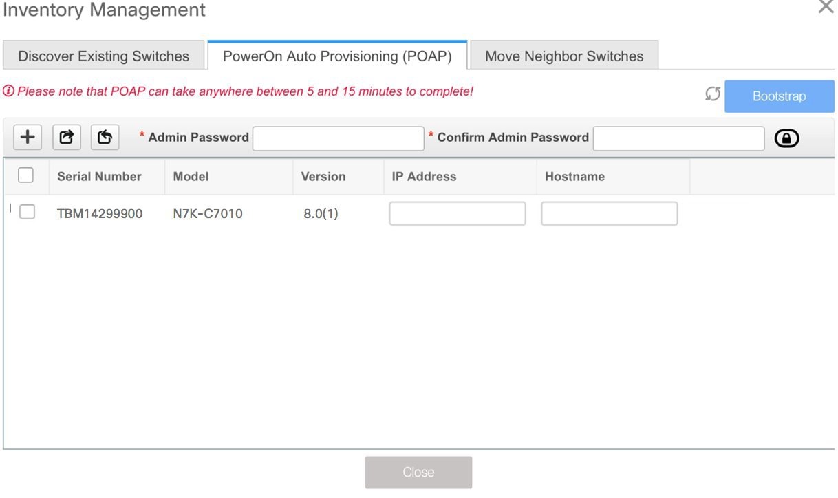 Select the checkbox next to the switch and add switch credentials: IP address and host name. Based on the IP address of your device, you can either add the IPv4 or IPv6 address in the IP Address field. Beginning with Release 11.2(1), you can provision devices in advance. To pre-provision devices, refer to Pre-provisioning a Device. |
||
| Step 10 |
In the Admin Password and Confirm Admin Password fields, enter and confirm the admin password. This admin password is applicable for all the switches displayed in the POAP window.
|
||
| Step 11 |
(Optional) Use discovery credentials for discovering switches.
|
||
| Step 12 |
Click Bootstrap at the top right part of the screen. DCNM provisions the management IP address and other credentials to the switch. In this simplified POAP process, all ports are opened up. |
||
| Step 13 |
After the bootstrapping is complete, close the Inventory Management screen to go to the fabric topology screen. |
||
| Step 14 |
In the fabric topology screen, from the Actions panel at the left part of the screen, click Refresh Topology. After the added switch completes POAP, the fabric builder topology screen displays the added switch with some physical connections. |
||
| Step 15 |
Monitor and check the switch for POAP completion. |
||
| Step 16 |
Click Save & Deploy at the top right part of the fabric builder topology screen to deploy pending configurations (such as template and interface configurations) onto the switches.
During fabric creation, if you have entered AAA server information (in the Manageability tab), you must update the AAA server password on each switch. Else, switch discovery fails. |
||
| Step 17 |
After the pending configurations are deployed, the Progress column displays 100% for all switches. |
||
| Step 18 |
Click Close to return to the fabric builder topology. |
||
| Step 19 |
Click Refresh Topology to view the update. All switches must be in green color indicating that they are functional. The switch and the link are discovered in DCNM. Configurations are built based on various policies (such as fabric, topology, and switch generated policies). The switch image (and other required) configurations are enabled on the switch. |
||
| Step 20 |
Right-click and select History to view the deployed configurations. 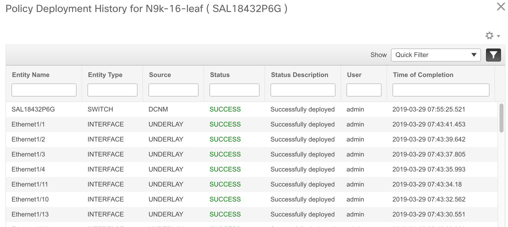 Click the Success link in the Status column for more details. An example: 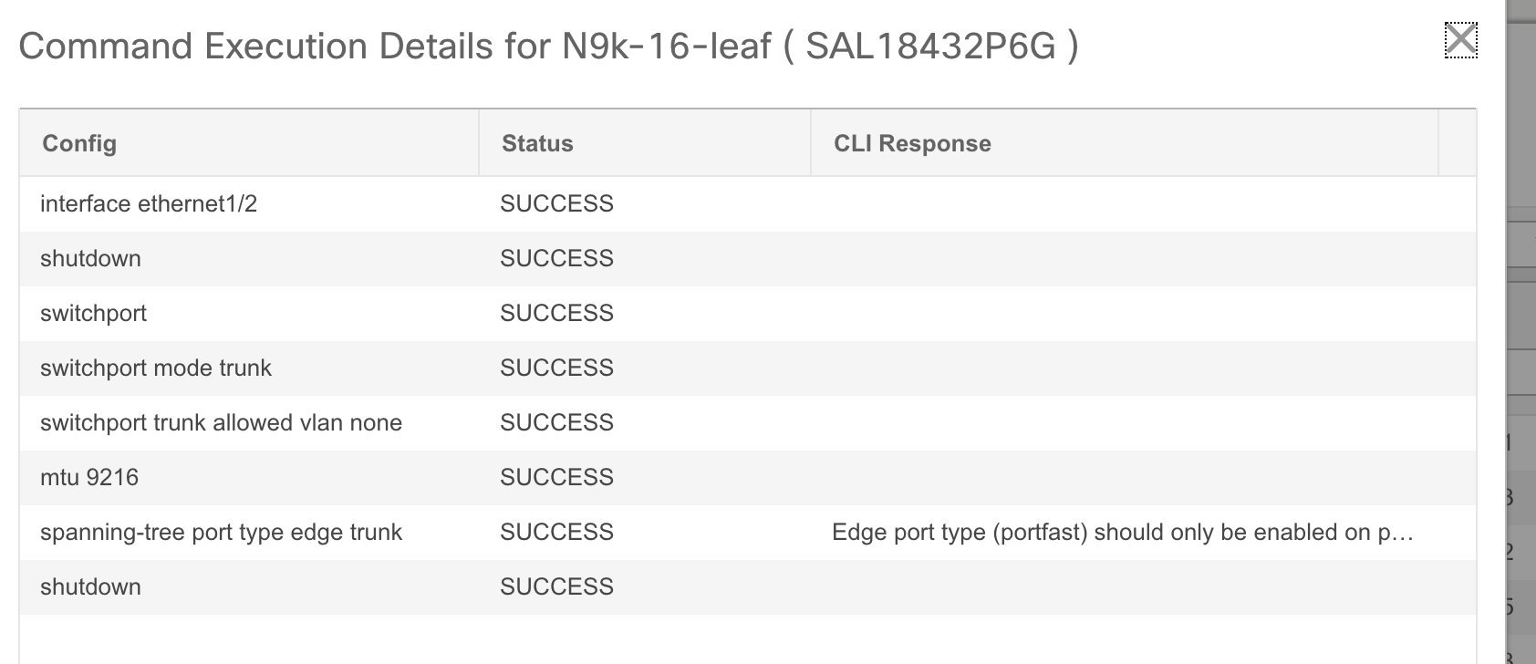 |
||
| Step 21 |
On the DCNM UI, the discovered switches can be seen in the fabric topology. Up to this step, the POAP is completed with basic settings. All the interfaces are set to trunk ports. You must setup interfaces through the Control > Interfaces option for any additional configurations, but not limited to the following:
|
Adding non-Nexus Devices to External Fabrics
You can discover the following non-Nexus devices in an external fabric:
-
IOS-XE family devices: Cisco CSR 1000v, Cisco IOS XE Gibraltar 16.10.x
-
IOS-XR family devices: ASR 9000 Series Routers, IOS XR Release 6.5.2 and Cisco NCS 5500 Series Routers, IOS XR Release 6.5.3
-
Arista 4.2 (Any model)
Only Cisco Nexus switches and Cisco CSR 1000v support SNMPv3 discovery. Hence, configure all the non-Nexus devices except Cisco CSR 1000v before adding it to the external fabric. However, Cisco DCNM can only access the basic device information like system name, serial number, model, version, interfaces, up time, and so on. Cisco DCNM does not support the CDP and LLDP of these devices.
The settings that are not applicable for non-Nexus devices appear blank, even if you get many options when you right-click a non-Nexus device in the fabric topology window. You cannot add or edit interfaces for ASR 9000 Series Routers and Arista switches.
See the Connecting Cisco Data Center and a Public Cloud chapter to see a use case to add Cisco CSR 1000v, Cisco IOS XE Gibraltar 16.10.x to an external fabric.
To add non-Nexus devices to an external fabric in the fabric topology window, perform the following steps:
Before you begin
Ensure that the configurations are pushed for non-Nexus devices before adding them to an external fabric. You cannot push configurations in a fabric in the monitor mode.
Procedure
| Step 1 |
Click Add switches in the Actions pane. The Inventory Management dialog box appears. |
||||||||||||
| Step 2 |
Enter values for the following fields under the Discover Existing Switches tab:
|
||||||||||||
| Step 3 |
Click Start Discovery. The fabric topology window appears, and a pop-up message appears at the bottom-right about the device discovery. For example: <ip-address> added for discovery
|
||||||||||||
| Step 4 |
Click Tabular view in the Actions pane. The switches and links window appears, where you can view the scan details. The discovery status is discovering in red with a warning icon next to it if the discovery is in progress. |
||||||||||||
| Step 5 |
View the details of the device. After the discovery of the device:
|
||||||||||||
| Step 6 |
Go back to the fabric topology window and refresh the topology. |
What to do next
Pre-provisioning a Device
Note |
Ensure that you enter DHCP details in the Bootstrap tab in the fabric settings. |
-
The pre-provisioned devices support the following configurations in DCNM:
-
Base management
-
vPC Pairing
-
Intra-Fabric links
-
Interface breakout configuration
-
-
The pre-provisioned devices do not support the following configurations in DCNM:
-
Inter-Fabric links
-
Host ports
-
vPCs to the access switches or hosts
-
FEX
-
Overlay network configurations
-
-
When a device is being pre-provisioned has breakout links, you need to specify the corresponding breakout command along with the switch's model and gateway in the Data field in the Add a new device to pre-provisioning window in order to generate the breakout PTI.
Note the following guidelines:
-
Multiple breakout commands can be separated by a semicolon (;).
-
The definitions of the fields in the data JSON object are as follows:
-
modulesModel: (Mandatory) Specifies the switch module’s model information.
-
gateway: (Mandatory) Specifies the default gateway for the management VRF on the switch. This field is required to create the intent to pre-provision devices. You need to enter the gateway even if it is in the same subnet as DCNM to create the intent as part of pre-provisioning a device.
-
breakout: (Optional) Specifies the breakout command provided in the switch.
-
portMode: (Optional) Specifies the port mode of the breakout interface.
-
The examples of the values in the Data field are as follows:
-
{"modulesModel": ["N9K-C93180LC-EX"], "gateway": "10.1.1.1/24"}
-
{"modulesModel": ["N9K-C93180LC-EX"],"breakout": "interface breakout module 1 port 1 map 10g-4x", "portMode": "hardware profile portmode 4x100G+28x40G", "gateway": "172.22.31.1/24" }
-
{"modulesModel": ["N9K-X9736C-EX", "N9K-X9732C-FX", "N9K-C9516-FM-E2", "N9K-C9516-FM-E2", "N9K-C9516-FM-E2", "N9K-C9516-FM-E2", "N9K-SUP-B+", "N9K-SC-A", "N9K-SC-A"], "gateway": "172.22.31.1/24"}
-
{"breakout":"interface breakout module 1 port 50 map 10g-4x" , "gateway": "172.16.1.1/24", "modulesModel": ["N9K-C93180YC-EX "]}
-
{"modulesModel": ["N9K-X9732C-EX", "N9K-X9732C-EX", "N9K-C9504-FM-E", "N9K-C9504-FM-E", "N9K-SUP-B", "N9K-SC-A", "N9K-SC-A"], "gateway": "172.29.171.1/24", "breakout":"interface breakout module 1 port 1,11,19 map 10g-4x; interface breakout module 1 port 7 map 25g-4x"}
-
Procedure
| Step 1 |
1. Click Control > Fabric Builder. The Fabric Builder screen is displayed. |
||
| Step 2 |
Click within the fabric box. |
||
| Step 3 |
From the Actions panel, click the Add switches option. The Inventory Management screen is displayed. |
||
| Step 4 |
Click the POAP tab. |
||
| Step 5 |
In the POAP tab, do the following:
IP Address: Specify the IPv4 or IPv6 address of the new device. For information about the Data field, see the examples provided in guidelines. The device details appear in the POAP screen. You can add more devices for pre-provisioning. At the top left part of the window, Export and Import icons are provided to export and import the .csv file that contains the switch information. Using the Import option, you can pre-provision multiple devices. Add new devices’ information in the .csv file with all the mandatory fields (SerialNumber, Model, version, IpAddress, Hostname and Data fields [JSON Object]). The Data column consists of the model name of the module to identify the hardware type from the fabric template. A .csv file screenshot: |
||
| Step 6 |
Enter the administration password in the Admin Password and Confirm Admin Password fields. |
||
| Step 7 |
Select the device(s) and click Bootstrap at the top right part of the screen. The leaf1 device appears in the external fabric topology. From the Actions panel, click Tabular View. You cannot deploy the fabric till the status of all the pre-provisioned switch(es) are displayed as ok under the Discovery Status column.
You need to click Save & Deploy in the fabric after the switch(es) are online to provision the host ports. This action must be performed before overlays are provisioned for the host port attachment. This is a representation of the leaf1 switch. When you connect leaf1 to the fabric, the switch is provisioned with the IP address 10.1.1.1. |
Configuration Compliance in External Fabrics
With external fabrics, any Nexus switch can be imported into the fabric, and there is no restriction on the type of deployment. It can be LAN Classic, VXLAN, FabricPath, vPC, HSRP, etc. When switches are imported into an external fabric, the configuration on the switches is retained so that it is non-disruptive. Only basic policies such as the switch username and mgmt0 interface are created after a switch import.
In the external fabric, for any intent that is defined in the DCNM, configuration compliance (CC) ensures that this intent is present on the corresponding switch. If this intent is not present on the switch, CC reports an OUT-OF-SYNC status. Additionally, there will be a Pending Config generated to push this intent to the switch to change the status to IN-SYNC. Any additional configuration that is on the switch but not in intent defined in DCNM, will be ignored by CC, as long as there is no conflict with anything in the intent.
When there is user-defined intent added on DCNM and the switch has additional configuration under the same top-level command, as mentioned earlier, CC will only ensure that the intent defined in DCNM is present on the switch. When this user defined intent on DCNM is deleted as a whole with the intention of removing it from the switch and the corresponding configuration exists on the switch, CC will report an OUT-OF-SYNC status for the switch and will generate Pending Config to remove the config from the switch. This Pending Config includes the removal of the top-level command. This action leads to removal of the other out-of-band configurations made on the switch under this top-level command as well. If you choose to override this behavior, the recommendation is that, you create a freeform policy and add the relevant top-level command to the freeform policy.
Let us see this behavior with an example.
-
A switch_freeform policy defined by the user in DCNM and deployed to the switch.
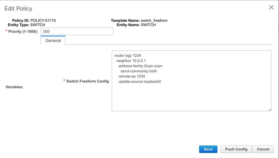
-
Additional configuration exists under router bgp in Running config that does not exist in user-defined DCNM intent Expected config. Note that there is no Pending Config to remove the additional config that exists on the switch without a user defined intent on DCNM.
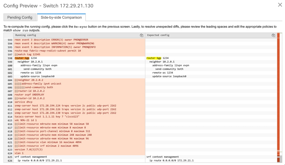
-
The Pending Config and the Side-by-side Comparison when the intent that was pushed earlier via DCNM is deleted from DCNM by deleting the switch_freeform policy that was created in the Step 1.
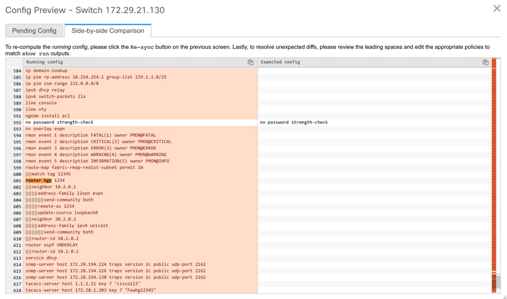
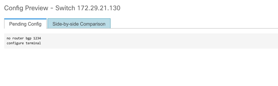
-
A switch_freeform policy with the top-level router bgp command needs to be created. This enables CC to generate the configuration needed to remove only the desired sub-config which was pushed from DCNM earlier.
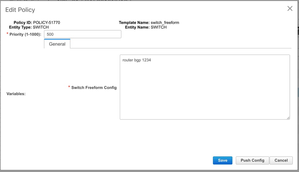
-
The removed configuration is only the subset of the configuration that was pushed earlier from DCNM.
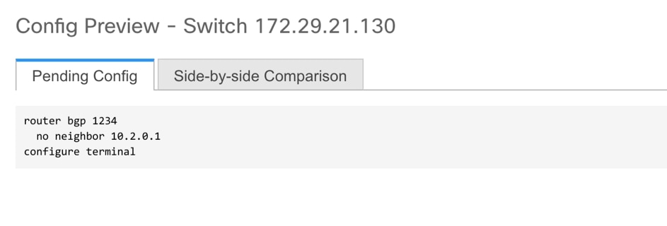
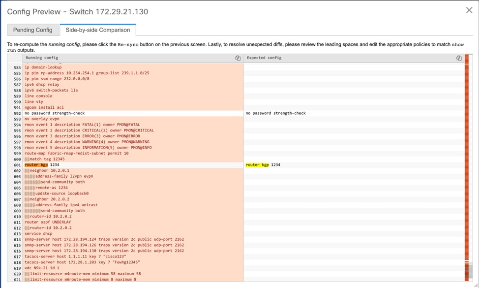
For interfaces on the switch in the external fabric, DCNM either manages the entire interface or does not manage it at all. CC checks interfaces in the following ways:
-
For any interface, if there is a policy defined and associated with it, then this interface is considered as managed. All configurations associated with this interface must be defined in the associated interface policy. This is applicable for both logical and physical interfaces. Otherwise, CC removes any out-of-band updates made to the interface to change the status to IN-SYNC.
-
Interfaces created out-of-band (applies for logical interfaces such as port-channels, sub interfaces, SVIs, loopbacks, etc.), will be discovered by DCNM as part of the regular discovery process. However, since there is no intent for these interfaces, CC will not report an OUT-OF-SYNC status for these interfaces.
-
For any interface, there can always be a monitor policy associated with it in DCNM. In this case, CC will ignore the interface’s configuration when it reports the IN-SYNC or OUT-OF-SYNC config compliance status.
-
Restore Fabric
Procedure
| Step 1 |
Choose Control > Fabrics > Fabric Builder and select a fabric. |
||||
| Step 2 |
Select Restore Fabric from the Actions menu. Restore Fabric window appears. |
||||
| Step 3 |
Select the time for which you want to restore the configuration. Valid values are 1m, 3m, 6m, YTD, 1y, and All. You can zoom into the graph. By default 1m, which is one month, backup information will be displayed. 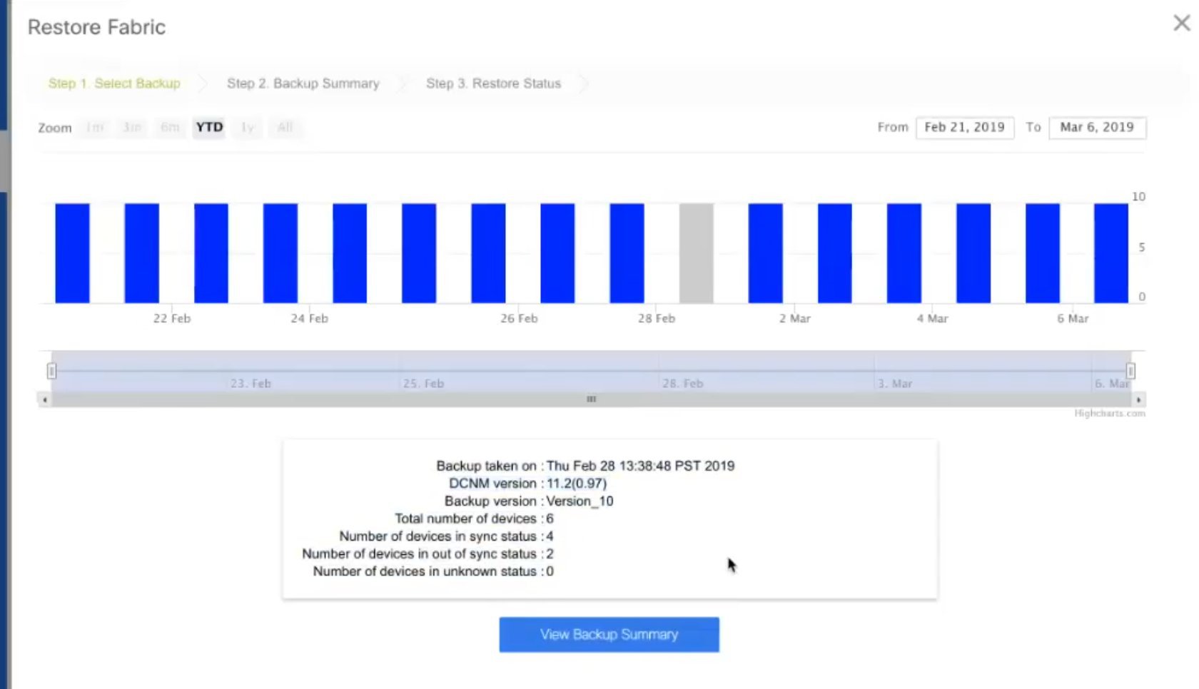 When you select a backup version, the vertical bar representing it turns grey, and corresponding information is displayed at the bottom part of the screen. It includes the backup date, DCNM version, total number of devices, number of devices in sync, and the number of devices out of sync. You can select a custom date range either by rearranging the date slide below the vertical bars, or using the From and To boxes at the top right part of the screen. |
||||
| Step 4 |
Choose the backup you want to restore. You can choose the automatic or manual backup. The automatic backup that is initiated from the Configuration Backup tab in the Fabric Settings dialog box. The manual backup is initiated by clicking Backup Now from the Actions pane in the fabric topology window. |
||||
| Step 5 |
Click Next to see the selected backup information of the devices in sync. The switch name, switch serial number, IP address, status, Restore Supported (indicating whether the device supports checkpoint rollback or not), the configuration details of the devices, and the VRF appear.
By default, the management VRF is displayed in the VRF column because it is used for the copy operation during the restore process. If you want to use a different VRF for the copy operation, update the VRF column. To update the same VRF for all devices, use the Apply for all devices option at the bottom left part of the screen. A sample screenshot: 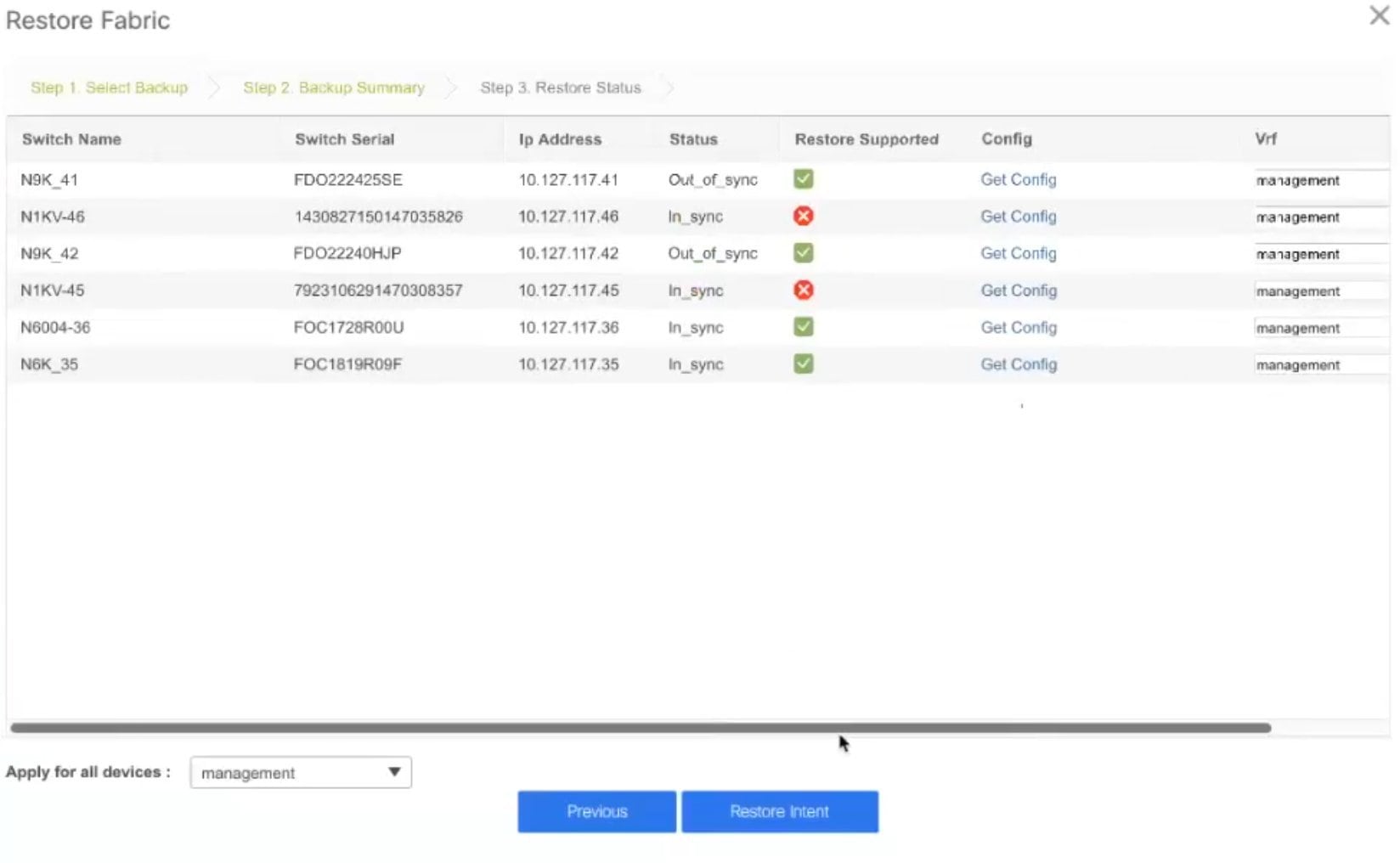
|
||||
| Step 6 |
Click Get Config to preview device configuration details. Config Preview window appears, which has three tabs.
|
||||
| Step 7 |
Go back to View Backup Summary window. |
||||
| Step 8 |
Click Restore Intent to proceed with the restoring. The Restore Status window appears. You can view the status of Validating Backup, Restoring fabric intent, Restoring underlay intent, Restoring interface intent, Restoring overlay intent and Restoring config for each switch. The valid values for the status of any action will be In Progress, Pending, Completed, or Failed.
|
||||
| Step 9 |
Click Close after the restore process is complete. |
Creating a vPC Setup in the External Fabric
Procedure
| Step 1 |
Right-click one of the two designated vPC switches and choose vPC Pairing. The Select vPC peer dialog box comes up. It contains a list of potential peer switches. Ensure that the Recommended column for the vPC peer switch is updated as true. |
| Step 2 |
Click the radio button next to the vPC peer switch and choose vpc_pair from the vPC Pair Template drop-down list. Only templates with the VPC_PAIR template sub type are listed here. 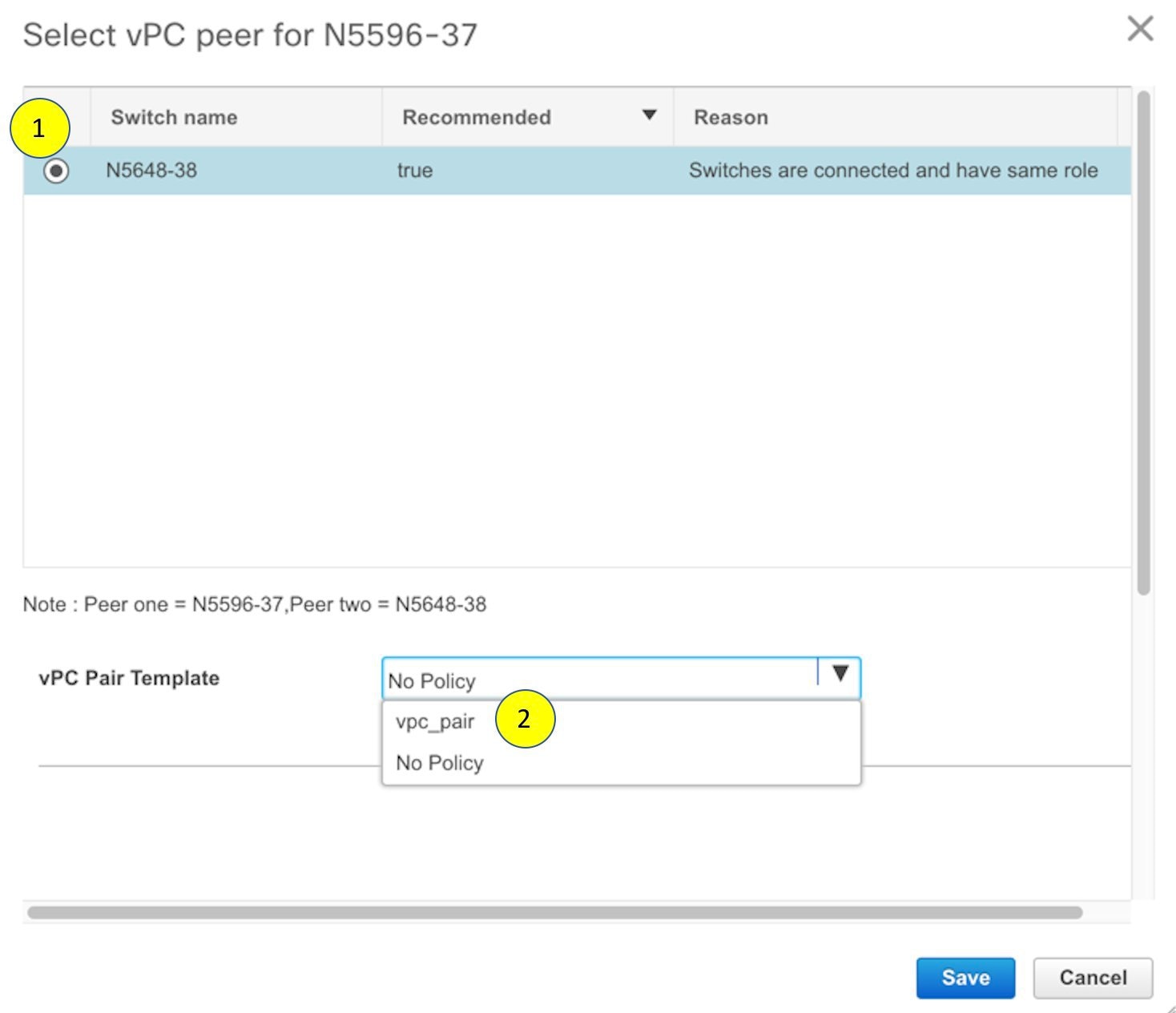 The vPC Domain and vPC Peerlink tabs appear. You must fill up the fields in the tabs to create the vPC setup. The description for each field is displayed at the extreme right. 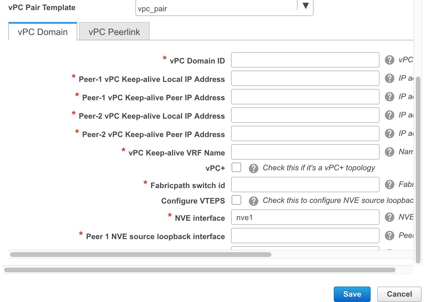 vPC Domain tab: Enter the vPC domain details. vPC+: If the switch is part of a FabricPath vPC + setup, enable this check box and enter the FabricPath switch ID field. Configure VTEPs: Check this check box to enter the source loopback IP addresses for the two vPC peer VTEPs and the loopback interface secondary IP address for NVE configuration. NVE interface: Enter the NVE interface. vPC pairing will configure only the source loopback interface. Use the freeform interface manager for additional configuration. NVE loopback configuration: Enter the IP address with the mask. vPC pairing will only configure primary and secondary IP address for loopback interface. Use the freeform interface manager for additional configuration. 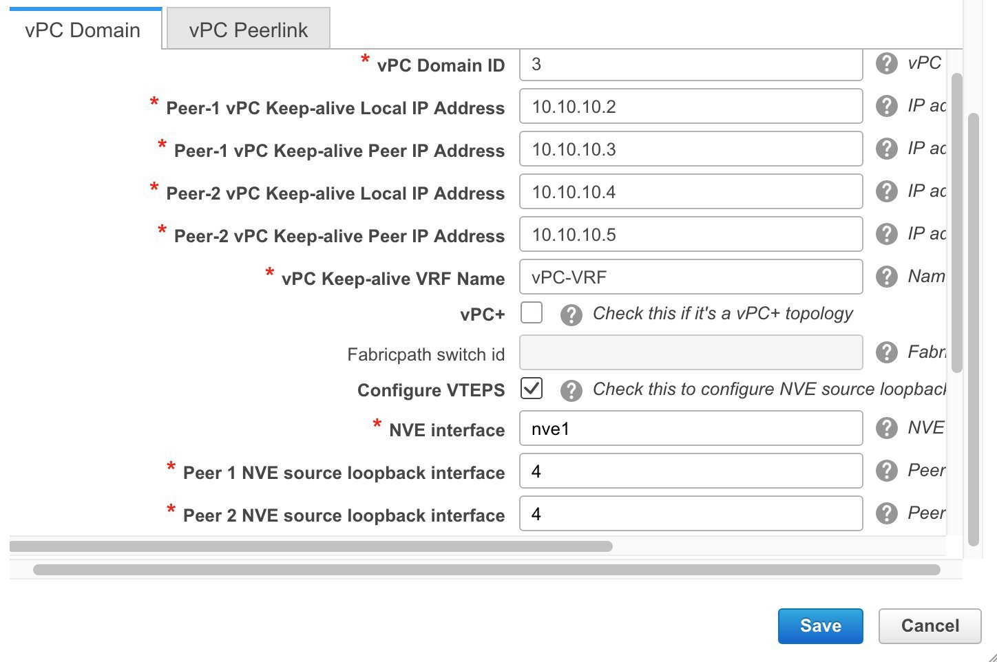 vPC Peerlink tab: Enter the vPC peer-link details. Switch Port Mode: Choose trunk or access or fabricpath. If you select trunk, then corresponding fields (Trunk Allowed VLANs and Native VLAN) are enabled. If you select access, then the Access VLAN field is enabled. If you select fabricpath, then the trunk and access port related fields are disabled. 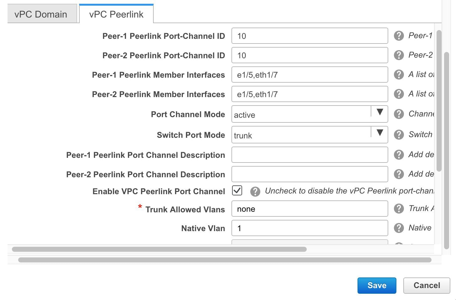 |
| Step 3 |
Click Save. The fabric topology window appears. The vPC setup is created. 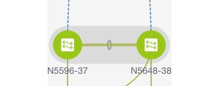 To update vPC setup details, do the following:
|
Undeploying a vPC Setup in the External Fabric
Procedure
| Step 1 |
Right-click a vPC switch and choose vPC Pairing. The vPC peer screen comes up. |
||
| Step 2 |
Click Unpair at the bottom right part of the screen. The vPC pair is deleted and the fabric topology window appears. |
||
| Step 3 |
Click Save & Deploy. The Config Deployment dialog box appears. |
||
| Step 4 |
(Optional) Click the value under the Preview Config column. View the pending configuration in the Config Preview dialog box. The following configuration details are deleted on the switch when you unpair: vPC feature, vPC domain, vPC peerlink, vPC peerlink member ports, loopback secondary IPs, and host vPCs. However, the host vPCs and port channels are not removed. Delete these port channels from the Interfaces window if required.
|
Multi-Site Domain for VXLAN BGP EVPN Fabrics
A Multi-Site Domain (MSD) is a multifabric container that is created to manage multiple member fabrics. An MSD is a single point of control for definition of overlay networks and VRFs that are shared across member fabrics. When you move fabrics (that are designated to be part of the multifabric overlay network domain) under the MSD as member fabrics, the member fabrics share the networks and VRFs created at the MSD-level. This way, you can consistently provision network and VRFs for different fabrics, at one go. It significantly reduces the time and complexity involving multiple fabric provisionings.
Since server networks and VRFs are shared across the member fabrics (as one stretched network), the new networks and VRFs provisioning function is provided at the MSD fabric level. Any new network and VRF creation is only allowed for the MSD. All member fabrics inherit any new network and VRF created for the MSD.
In DCNM 11.1(1) release, in addition to member fabrics, the topology view for the MSD fabric is introduced. This view displays all member fabrics, and how they are connected to each other, in one view.
Also, a deployment view is introduced for the MSD fabric. You can deploy overlay networks (and VRFs) on member fabrics from a single topology deployment screen, instead of visiting each member fabric deployment screen separately and deploying.
Note |
|
A few fabric-specific terms:
-
Standalone fabric: A fabric that is not part of an MSD is referred as a standalone fabric from the MSD perspective. Before the MSD concept, all fabrics were considered standalone, though two or more such fabrics can be connected with each other.
-
Member fabrics: Fabrics that are part of an MSD are called member fabrics or members. Create a standalone fabric (of the type Easy_Fabric) first and then move it within an MSD as a member fabric.
When a standalone fabric is added to the MSD, the following actions take place:
-
The standalone fabric's relevant attributes and the network and VRF definitions are checked against that of the MSD. If there is a conflict, then the standalone fabric addition to the MSD fails. If there are no conflicts, then the standalone fabric becomes a member fabric for the MSD. If there is a conflict, the exact conflicts are logged in the pending errors log for the MSD fabric. You can remedy the conflicts and then attempt to add the standalone fabric to the MSD again.
-
All the VRFs and networks definitions from the standalone fabric that do not have presence in the MSD are copied over to the MSD and in turn inherited to each of its other existing member fabrics.
-
The VRFs (and their definitions) from the MSD (such as the MSD's VRF, and L2 and L3 VNI parameters that do not have presence in the standalone fabric) are inherited into the standalone fabric that just became a member.
Fabric and Switch Instance Variables
While the MSD provisions a global range of network and VRF values, some parameters are fabric-specific and some parameters are switch-specific. The parameters are called fabric instance and switch instance variables.
Fabric instance values can only be edited or updated in the fabric context from the VRFs and Networks window. The appropriate fabric should be selected in the SCOPE drop-down list to edit the fabric instance values. Some of the examples of fabric instance variables are BGP ASN, Multicast group per network or VRF, etc. For information about editing multicast group address, see Editing Networks in the Member Fabric.
Switch instance values can be edited on deployment of the network on the switch. For example, VLAN ID.
MSD and Member Fabric Process Flow
An MSD has multiple sites (and hence, multiple member fabrics under an MSD). VRFs and networks are created for the MSD and get inherited by the member fabrics. For example, VRF-50000 (and L3 network with ID 50000), and L2 networks with IDs 30000 and 30001 are created for the MSD, in one go.
A high-level flow chart of the MSD and member fabric creation and MSD-to-member fabric inheritance process:
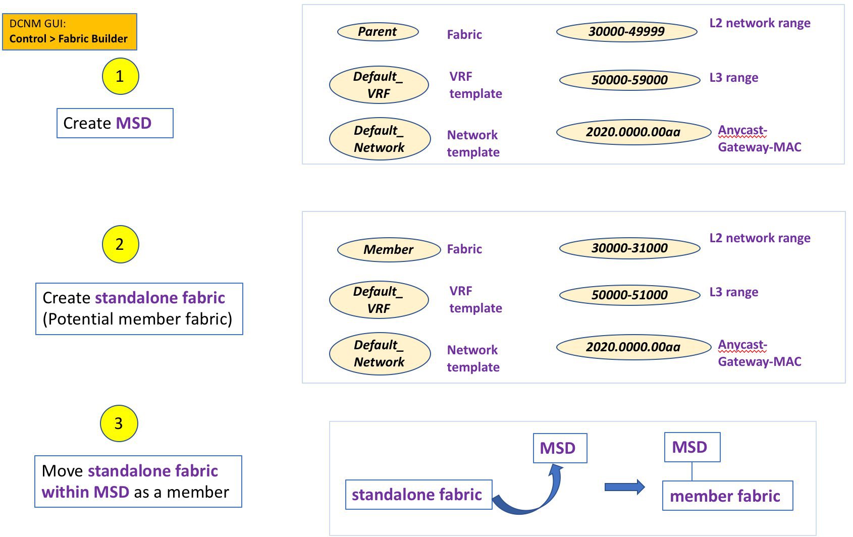
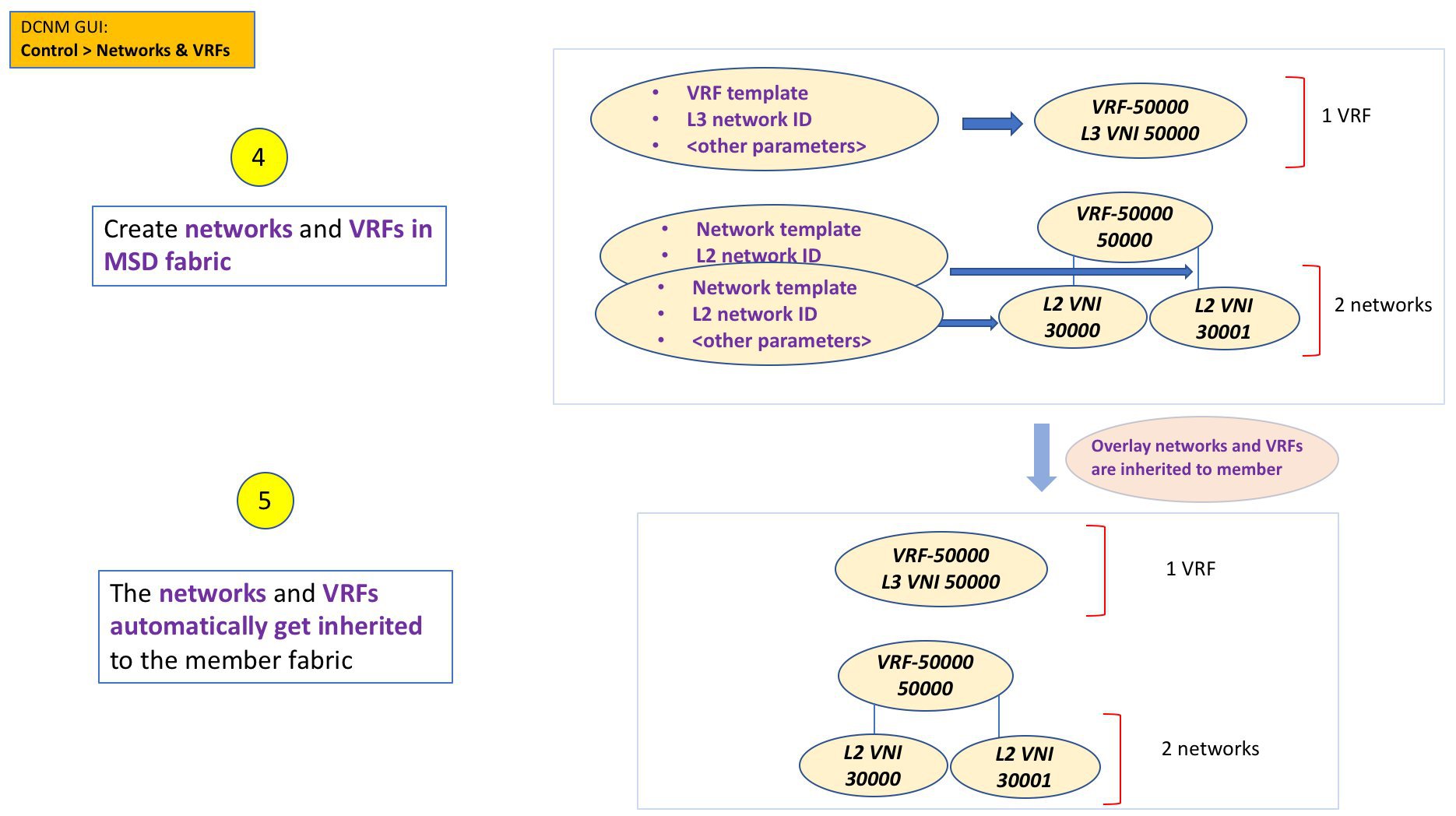
The sample flow explained the inheritance from the MSD to one member. An MSD has multiple sites (and hence, multiple member fabrics under an MSD). A sample flow from an MSD to multiple members:
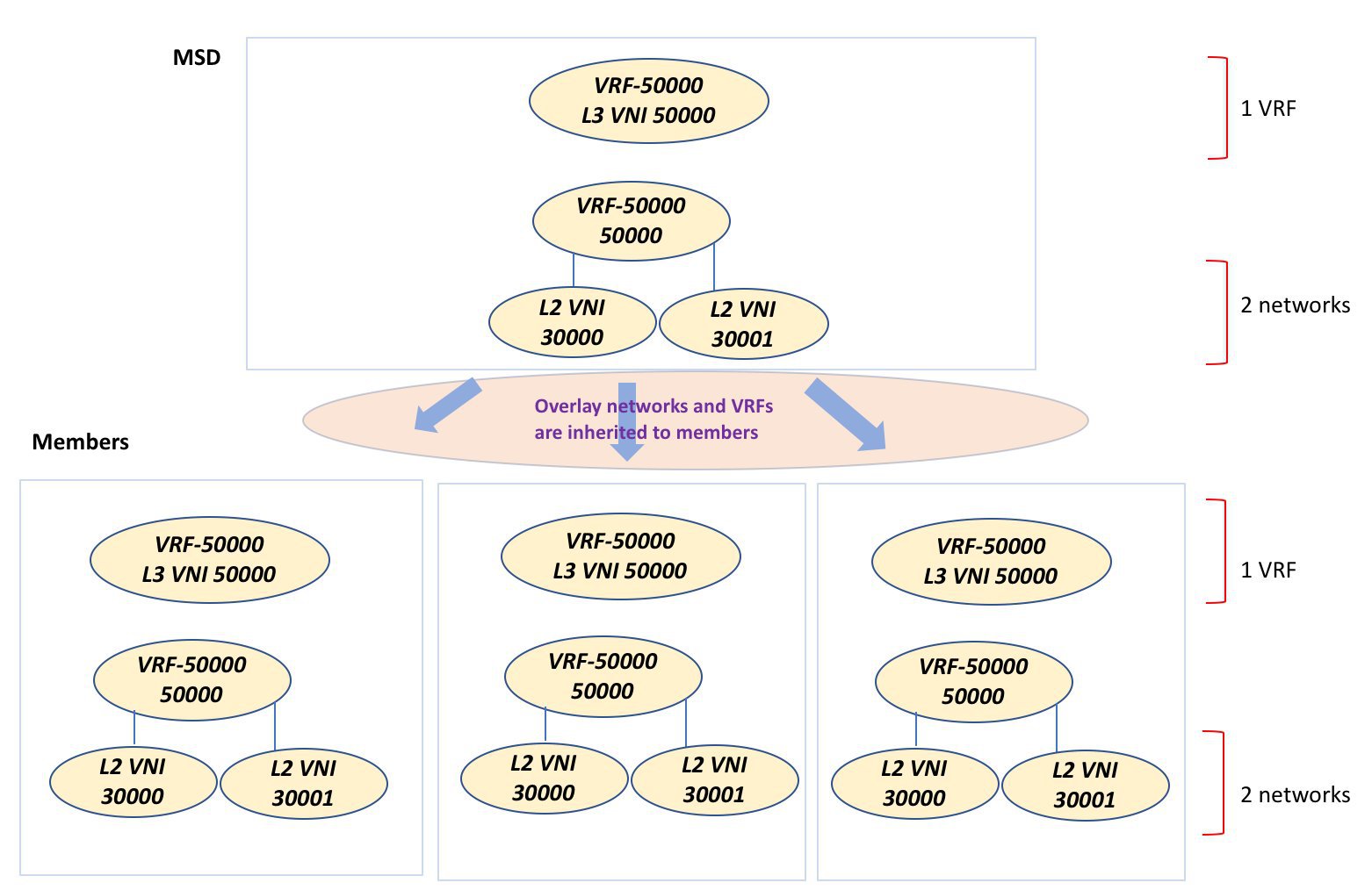
In this example, VRF-50000 (and L3 network with ID 50000), and L2 networks with IDs 30000 and 30001 are created in one go. Networks and VRFs are deployed on the member fabric switches, one after another, as depicted in the image.
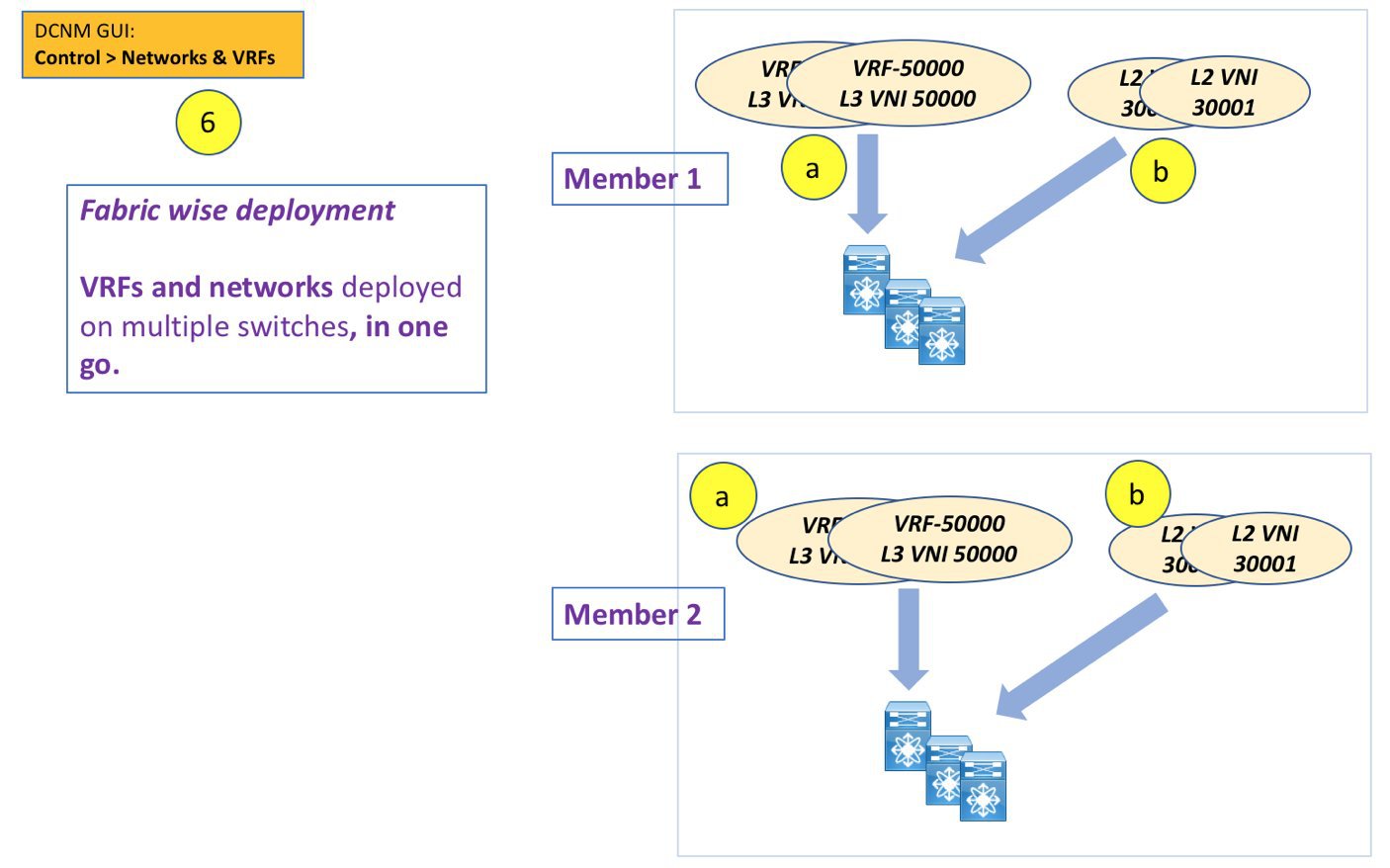
In DCNM 11.1(1), you can provision overlay networks through a single MSD deployment screen.
Note |
If you move a standalone fabric with existing networks and VRFs to an MSD, DCNM does appropriate validation. This is explained in detail in an upcoming section. |
Upcoming sections in the document explain the following:
-
Creation of an MSD fabric.
-
Creation of a standalone fabric (as a potential member) and its movement under the MSD as a member.
-
Creation of networks and VRFs in the MSD and their inheritance to the member fabrics.
-
Deployment of networks and VRFs from the MSD and member fabric topology views.
-
Other scenarios for fabric movement:
-
Standalone fabric with existing networks and VRFs to an MSD fabric.
-
Member fabric from one MSD to another.
-
Creating an MSD Fabric and Associating Member Fabrics to It
The process is explained in two steps:
-
Create an MSD fabric.
-
Create a new standalone fabric and move it under the MSD fabric as a member fabric.
Creating an MSD Fabric
-
Click Control > Fabric Builder.
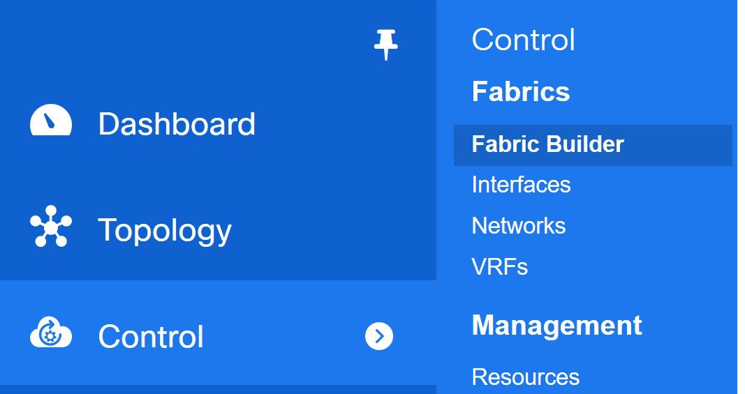
The Fabric Builder screen comes up. When you view the screen for the first time, the Fabrics section has no entries. After you create a fabric, it is displayed on the Fabric Builder screen, wherein a rectangular box represents each fabric.
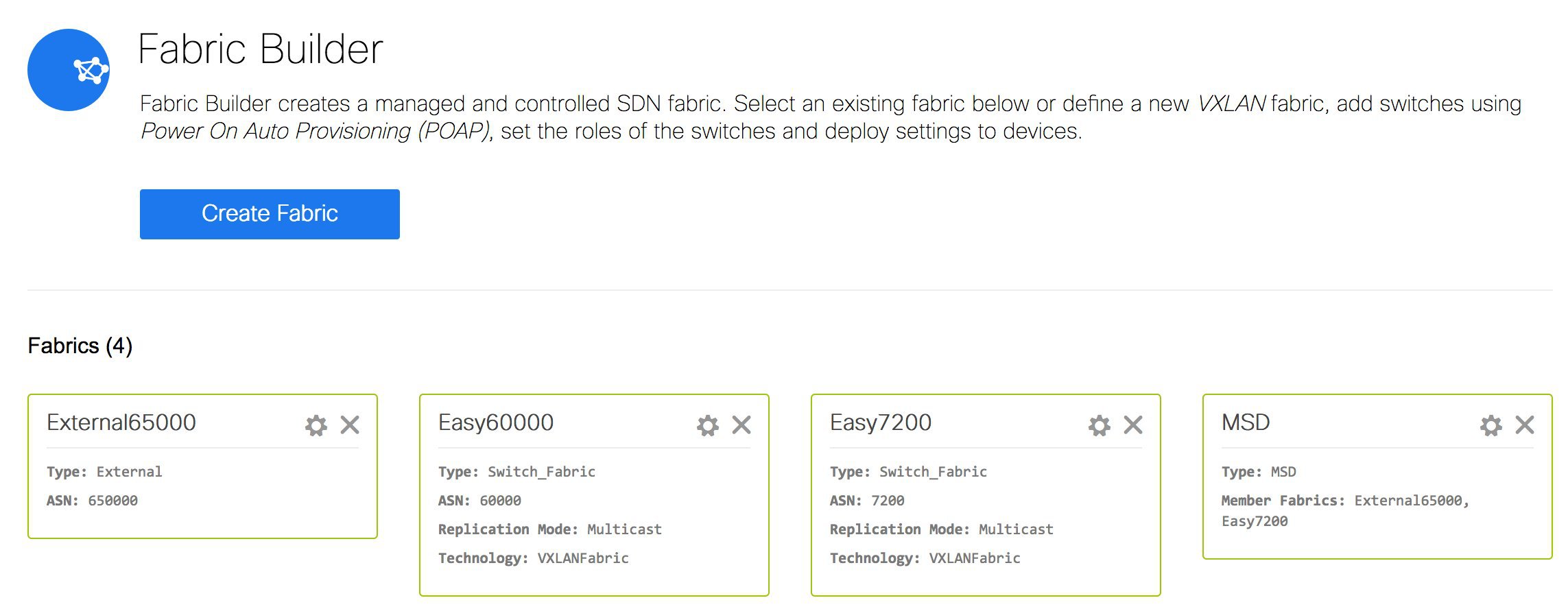
A standalone or member fabric contains Switch_Fabric in the Type field, its AS number in the ASN field and mode of replication, Multicast or Ingress Replication, in the Replication Mode field. Since no device or network traffic is associated with an MSD fabric as it is a container, it does not have these fields.
-
Click the Create Fabric button. The Add Fabric screen comes up. The fields are:
Fabric Name - Enter the name of the fabric.
Fabric Template - This field has template options for creating specific types of fabric. Choose MSD_Fabric. The MSD screen comes up.
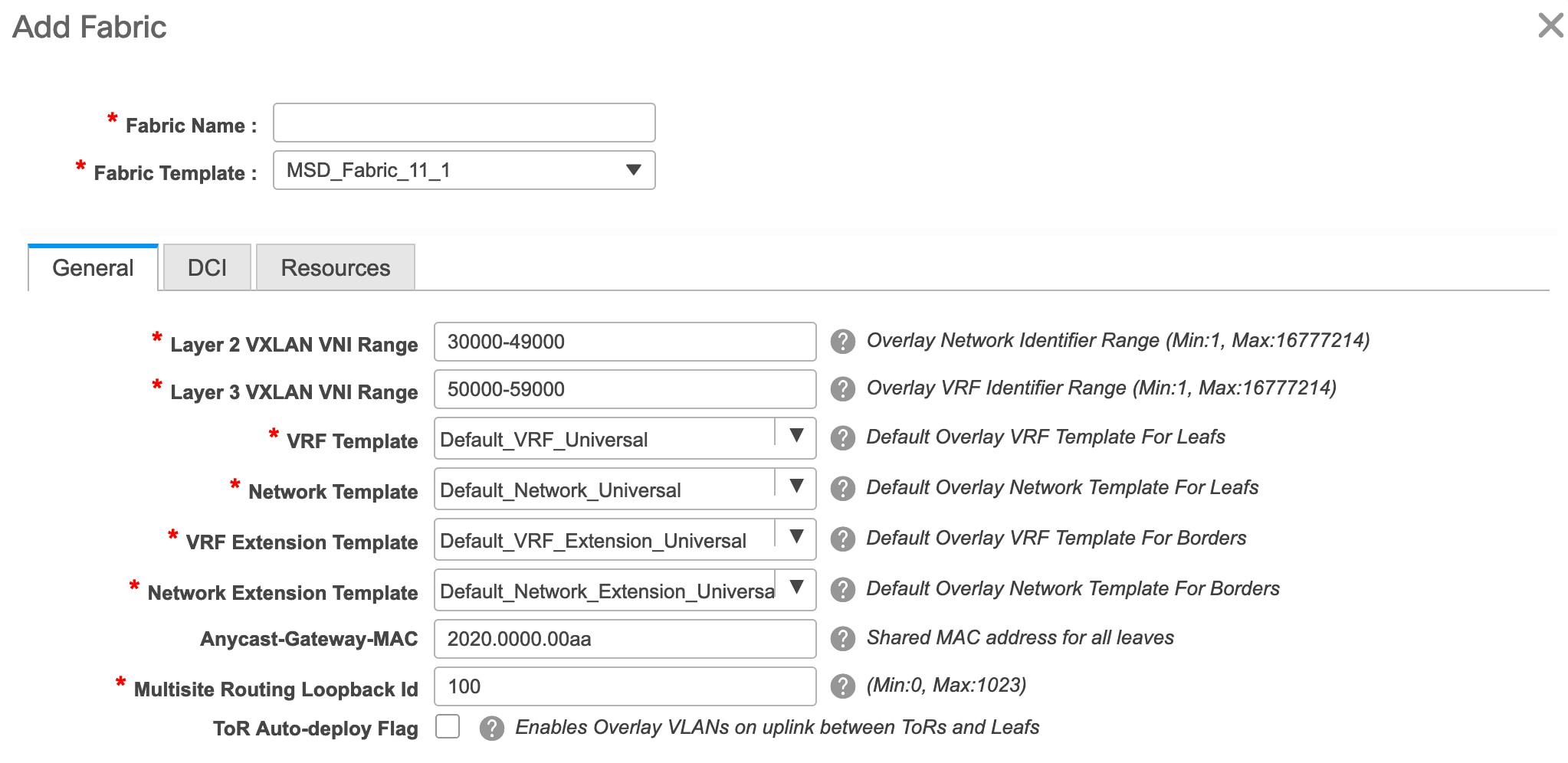
The fields in the screen are explained:
In the General tab, all fields are autopopulated with data. The fields consist of the Layer 2 and Layer 3 VXLAN segment identifier range, the default network and VRF templates, and the anycast gateway MAC address. Update the relevant fields as needed.
Layer 2 VXLAN VNI Range - Layer 2 VXLAN segment identifier range.
Layer 3 VXLAN VNI Range - Layer 3 VXLAN segment identifier range.
VRF Template - Default VRF template.
Network Template - Default network template.
VRF Extension Template - Default VRF extension template.
Network Extension Template - Default network extension template.
Anycast-Gateway-MAC - Anycast gateway MAC address.
Multisite Routing Loopback Id – The multicast routing loopback ID is populated in this field.
ToR Auto-deploy Flag - Select this check box to enable automatic deployment of the networks and VRFs in the Easy Fabric to the ToR switches in the External Fabric when you click Save & Deploy in the MSD fabric.
-
Click the DCI tab.
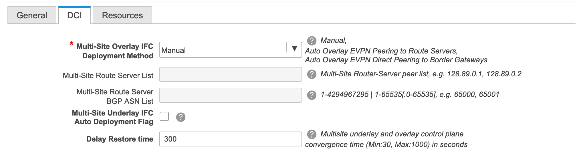
The fields are:
Multi-Site Overlay IFC Deploy Method – Choose how you will connect the data centers through the BGW, manually, in a back-to-back fashion or through a route server.
If you choose to connect them through a route server, you should enter the route server details.
Multi-Site Route Server List – Specify the IP addresses of the route server. If you specify more than one, separate the IP addresses by a comma.
Multi-Site Route Server BGP ASN List – Specify the BGP AS Number of the router server. If you specify more than one route server, separate the AS Numbers by a comma.
Multi-Site Underlay IFC Auto Deployment Flag - Check the check box to enable auto configuration. Uncheck the check box for manual configuration.
Delay Restore Time - Specifies the multi-site underlay and overlay control planes convergence time. The minimum value is 30 seconds and the maximum value is 1000 seconds.
-
Click the Resources tab.
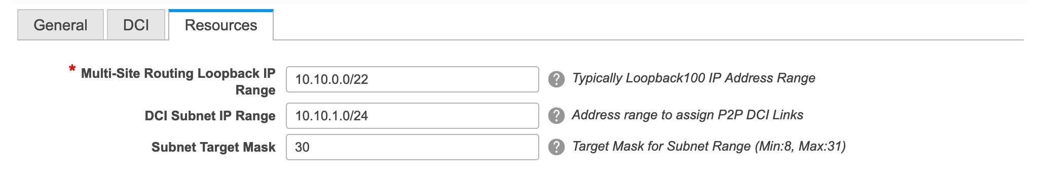
MultiSite Routing Loopback IP Range – Specify the Multi-Site loopback IP address range used for the EVPN Multi-Site function.
A unique loopback IP address is assigned from this range to each member fabric because each member site must have a Loopback 100 IP address assigned for overlay network reachability. The per-fabric loopback IP address is assigned on all the BGWs in a specific member fabric.
DCI Subnet IP Range and Subnet Target Mask – Specify the Data Center Interconnect (DCI) subnet IP address and mask.
-
Click Save.
A message appears briefly at the bottom right part of the screen, indicating that you have created a new MSD fabric. After fabric creation, the fabric page comes up. The fabric name MSD-Parent-Fabric appears at the top left part of the screen.
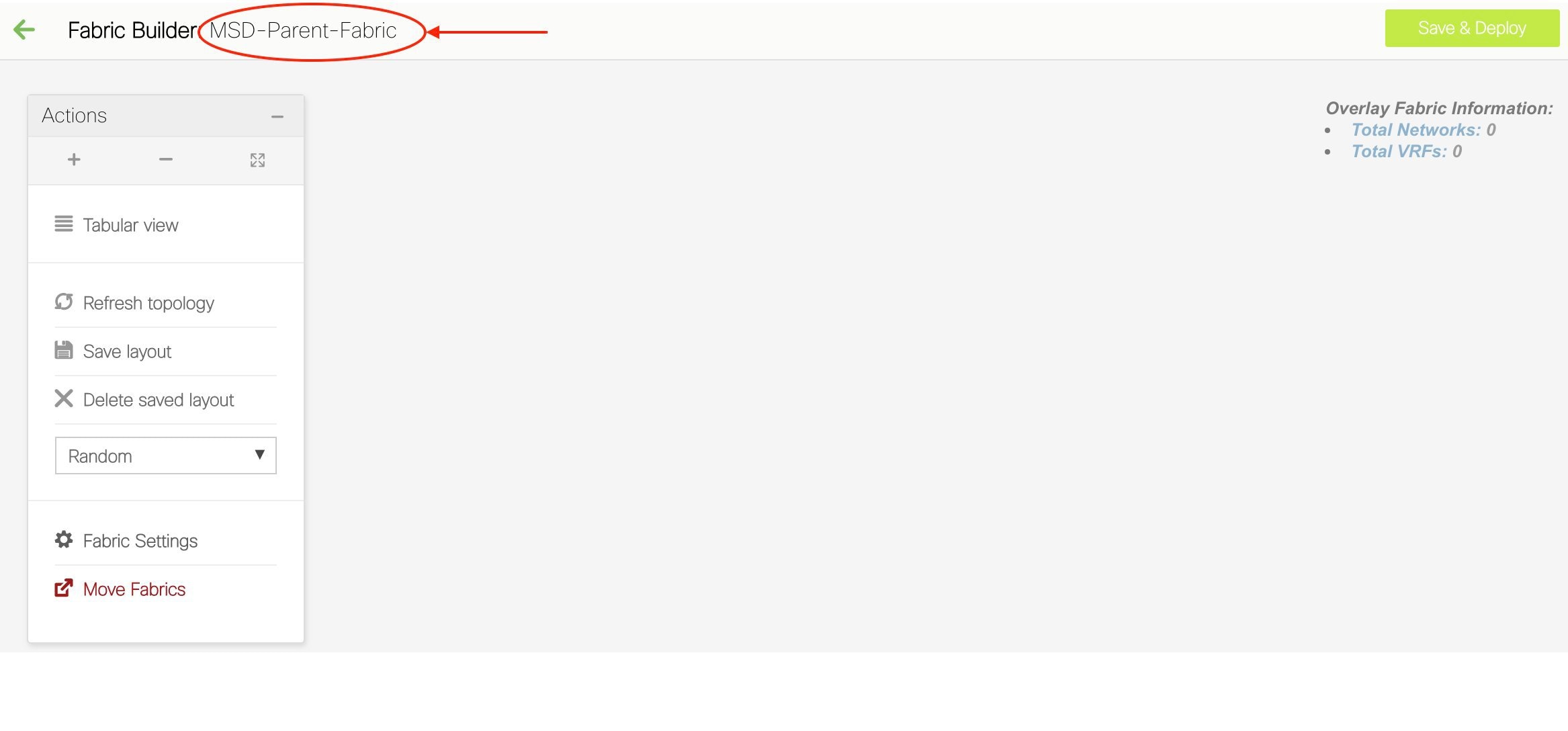
Since the MSD fabric is a container, you cannot add a switch to it. The Add Switches button that is available in the Actions panel for member and standalone fabrics is not available for the MSD fabric.
When a new MSD is created, the newly created MSD fabric instance appears (as a rectangular box) on the Fabric Builder page. To go to the Fabric Builder page, click the ← button at the top left part of the MSD-Parent-Fabric page.
An MSD fabric is displayed as MSD in the Type field, and it contains the member fabric names in the Member Fabrics field. When no member fabric is created, None is displayed.
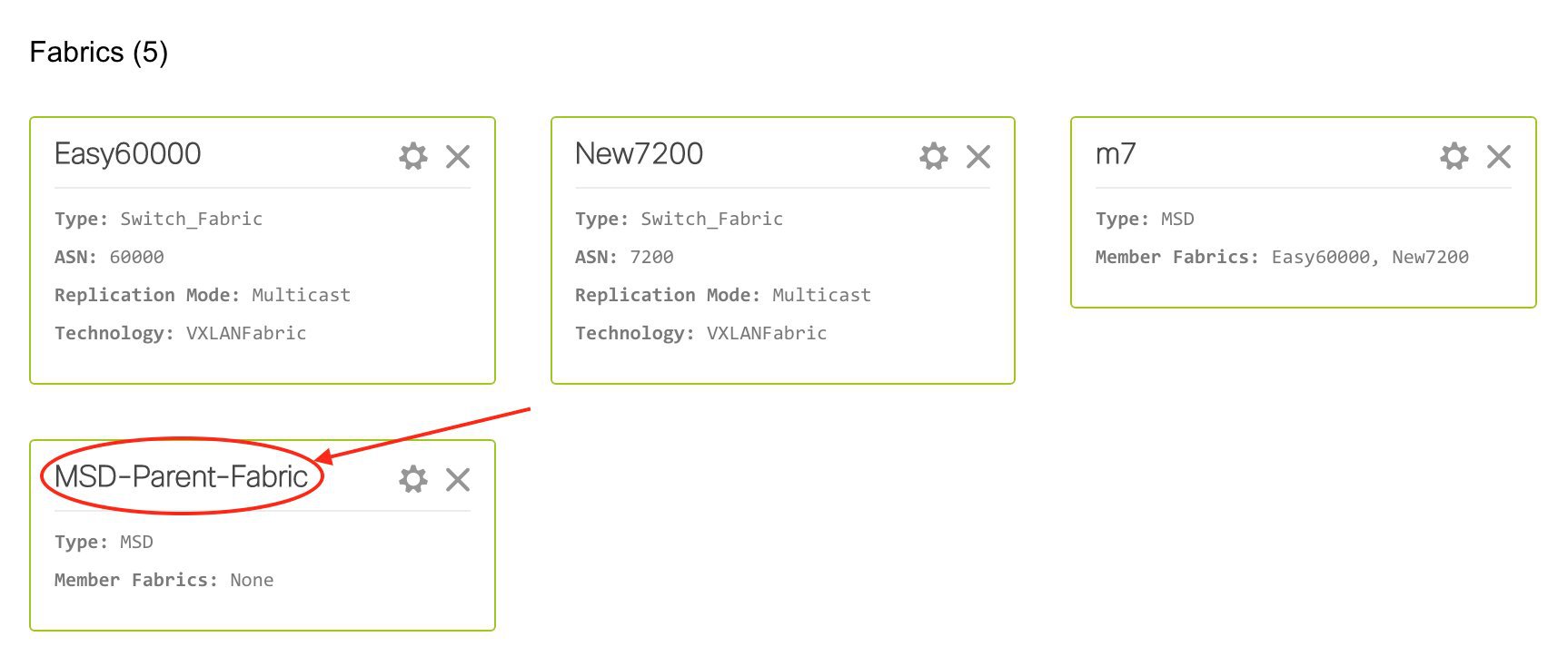
The steps for creation of an MSD fabric and moving member fabrics under it are:
-
Create an MSD fabric.
-
Create a new standalone fabric and move it under the MSD fabric as a member fabric.
Step 1 is completed. Step 2 is explained in the next section.
Creating and Moving a New Fabric Under the MSD Fabric as a Member
A new fabric is created as a standalone fabric. After you create a new fabric, you can move it under an MSD as a member. As a best practice, when you create a new fabric that is a potential member fabric (of an MSD), do not add networks and VRFs to the fabric. Move the fabric under the MSD and then add networks and VRFs for the MSD. That way, there will not be any need for validation (or conflict resolution) between the member and MSD fabric network and VRF parameters.
New fabric creation is explained in the Easy Fabric creation process. In the MSD document, fabric movement is covered. However, some pointers about a standalone (potential member) fabric:
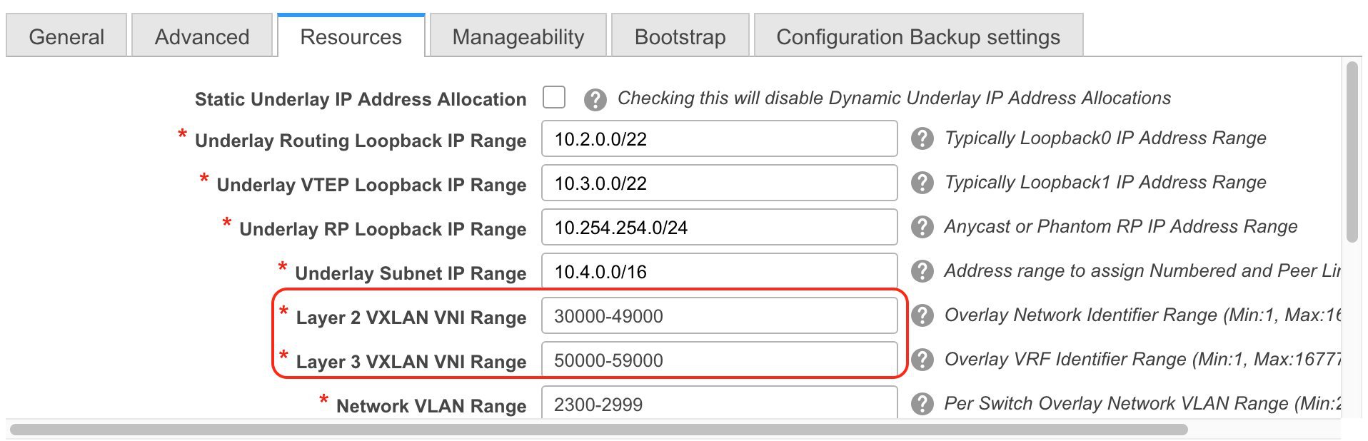
The values that are displayed in the screen are automatically generated. The VXLAN VNI ID ranges (in the L2 Segment ID Range and L3 Partition ID Range fields) allocated for new network and VRF creation are values from the MSD fabric segment ID range. If you want to update the VXLAN VNI ranges or the VRF and Network VLAN ranges, ensure the following:
-
If you update a range of values, ensure that it does not overlap with other ranges.
-
You must update one range of values at a time. If you want to update more than one range of values, do it in separate instances. For example, if you want to update L2 and L3 ranges, you should do the following:
-
Update the L2 range and click Save.
-
Click the Edit Fabric option again, update the L3 range and click Save.
-
Ensure that the Anycast Gateway MAC, the Network Template and the VRF Template field values are the same as the MSD fabric. Else, member fabric movement to the MSD fail.
Other pointers:
-
Ensure that the Anycast Gateway MAC, the Network Template and the VRF Template field values are the same as the MSD fabric. Else, member fabric movement to the MSD fail.
-
The member fabric should have a Site ID configured and the Site ID must be unique among the members.
-
The BGP AS number should be unique for a member fabric.
-
The underlay subnet range for loopback0 should be unique.
-
The underlay subnet range for loopback1 should be unique.
After you click Save, a note appears at the bottom right part of the screen indicating that the fabric is created. When a fabric is created, the fabric page comes up. The fabric name appears at the top left part of the screen.
Simultaneously, the Fabric Builder page also displays the newly created fabric, Member1.
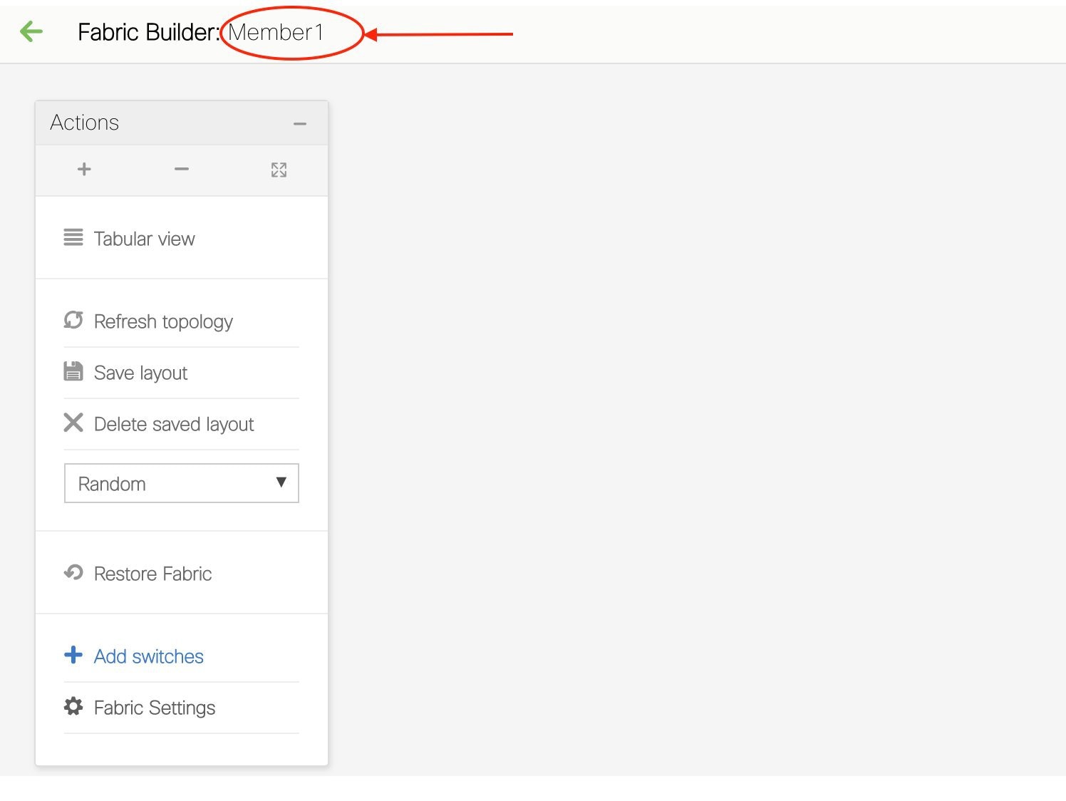
Simultaneously, the Fabric Builder page also displays the newly created fabric, Member1.
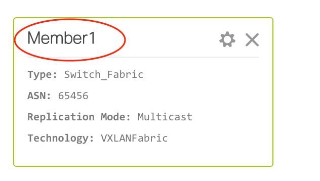
Moving the Member1 Fabric Under MSD-Parent-Fabric
You should go to the MSD fabric page to associate a member fabric under it.
If you are on the Fabric Builder page, click within the MSD-Parent-Fabric box to go to the MSD-Parent-Fabric page.
[If you are in the Member1 fabric page, you should go to the MSD-Parent-Fabrics-Docs fabric page. Click <- above the Actions panel. You will reach the Fabric Builder page. Click within the MSD-Parent-Fabric box].
-
In the MSD-Parent-Fabric page, go to the Actions panel and click Move Fabrics.
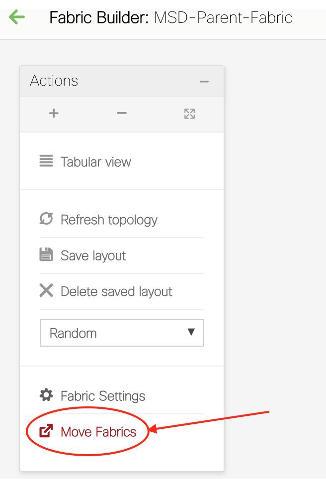
The Move Fabric screen comes up. It contains a list of fabrics.
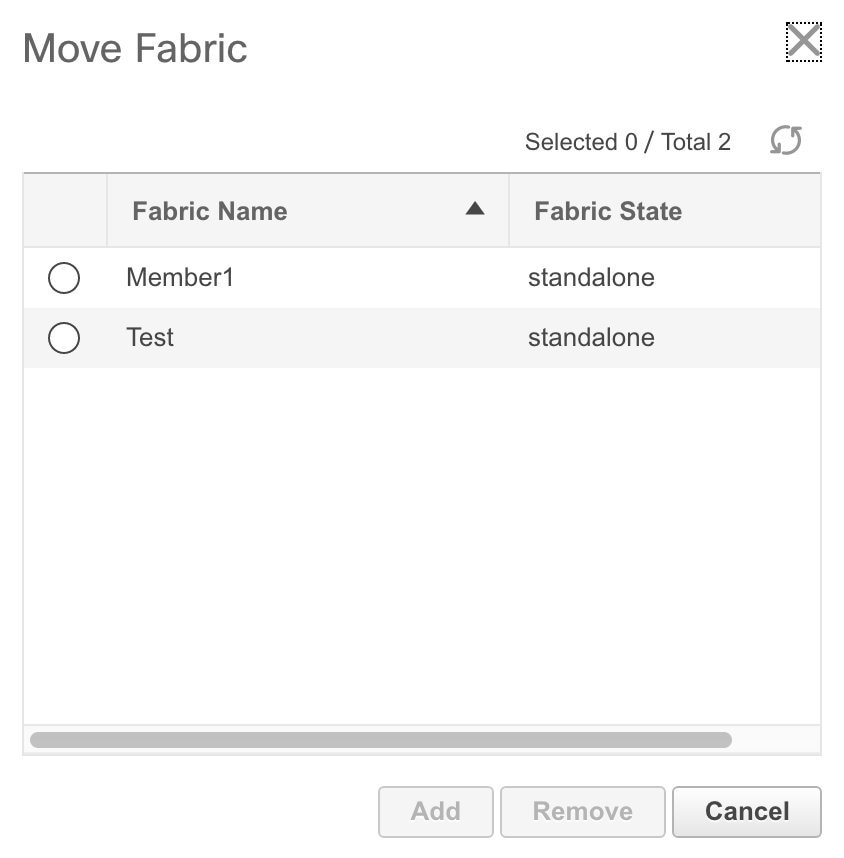
Member fabrics of other MSD container fabrics are not displayed here.
The Member1 fabric is still a standalone fabric. A fabric is considered a member fabric of an MSD fabric only when you associate it with the MSD fabric. Also, each standalone fabric is a candidate for being an MSD fabric member, until you associate it to one of the MSD fabrics.
-
Since Member1 fabric is to be associated with the MSD fabric, select the Member1 radio button. The Add button is enabled.
-
Click Add.
Immediately, a message appears at the top of the screen indicating that the Member1 fabric is now associated with the MSD fabric MSD-Parent-Fabric. Now, the MSD-Parent-Fabric fabric page appears again.
-
Click the Move Fabrics option to check the fabric status. You can see that the fabric status has changed from standalone to member.
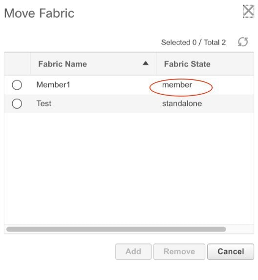
-
Close this screen.
-
Click ← above the Actions panel to go to the Fabric Builder page.
You can see that Member1 is now added to MSD fabric and is displayed in the Member Fabrics field.
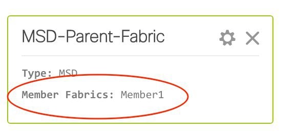
MSD Fabric Topology View Pointers
-
MSD fabric topology view - Member fabrics and their switches are displayed. A boundary defines each member fabric. All fabric devices of the fabric are confined to the boundary.
All links are displayed, including intra-fabric links and Multi-Site (underlay and overlay), and VRF Lite links to remote fabrics.
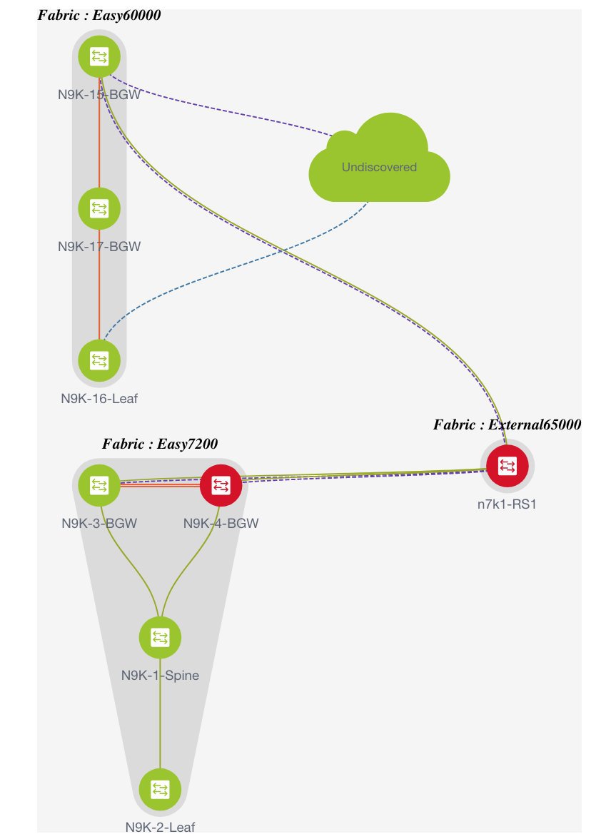
-
Member fabric topology view - A member fabric and its switches are displayed. In addition, the connected external fabric is displayed.
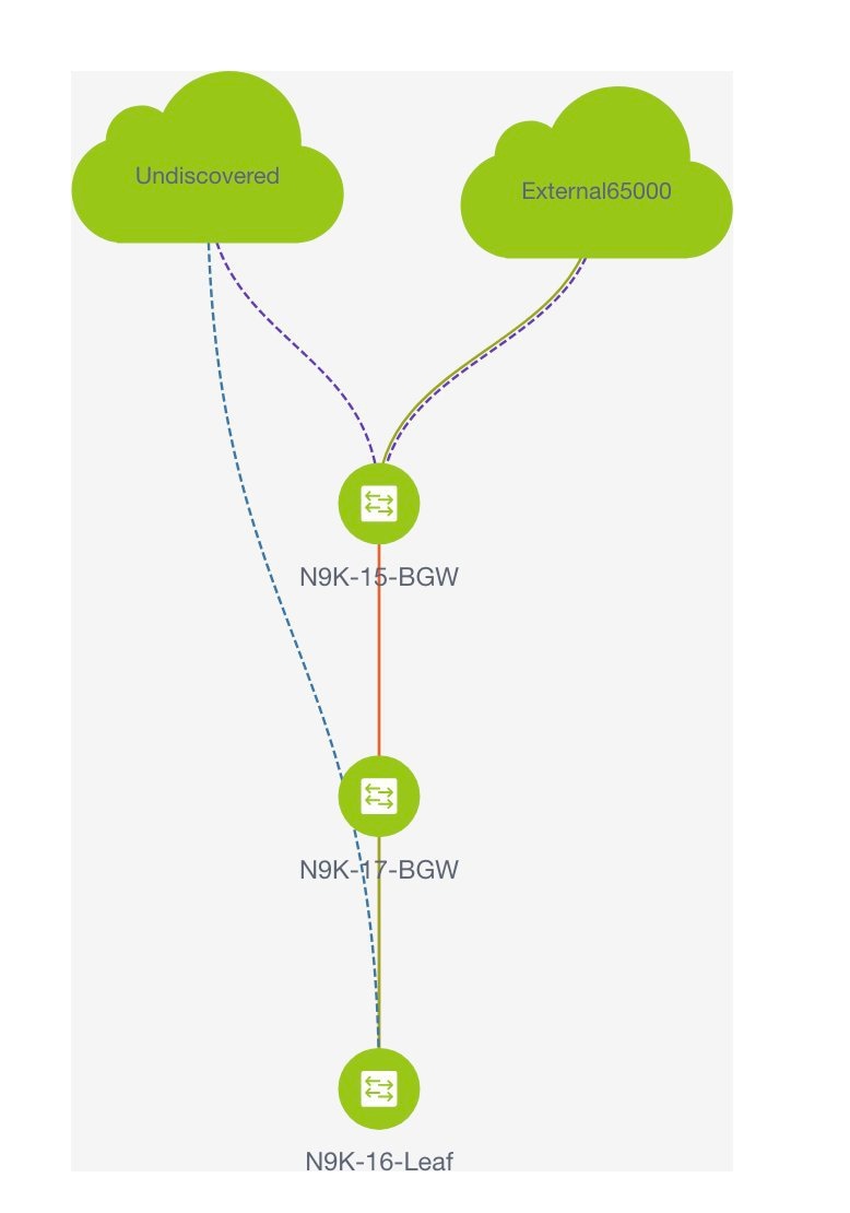
-
A boundary defines a standalone VXLAN fabric, and each member fabric in an MSD fabric. A fabric’s devices are confined to the fabric boundary. You can move a switch icon by dragging it. For a better user experience, in addition to switches, DNCM 11.2(1) release allows you to move an entire fabric. To move a fabric, place the cursor within the fabric boundary (but not on a switch icon), and drag it in the desired direction.
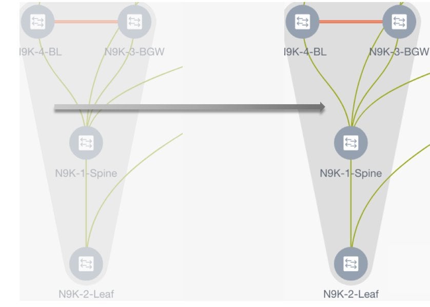
Adding and Editing Links
To add a link, right-click anywhere in the topology and use the Add Link option. To edit a link, right-click on the link and use the Edit Link option.
Alternatively, you can use the Tabular view option in the Actions panel.
To know how to add links between border switches of different fabrics (inter-fabric links) or between switches in the same fabric (intra-fabric links), refer the Fabric Links topic.
Creating and Deploying Networks and VRFs in an MSD Fabric
In standalone fabrics, networks and VRFs are created for each fabric. In an MSD fabric, networks and VRFs should be created at the MSD fabric level. The networks and VRFs are inherited by all the member networks. You cannot create or delete networks and VRFs for member fabrics. However, you can edit them.
For example, consider an MSD fabric with two member fabrics. If you create three networks in the MSD fabric, then all three networks will automatically be available for deployment in both the member fabrics.
Though member fabrics inherit the MSD fabric's networks and VRFs, you have to deploy the networks and VRFs distinctly, for each fabric.
In DCNM 11.1(1) release, a deployment view is introduced for the MSD, in addition to the per-fabric deployment view. In this view, you can view and provision overlay networks for all member fabrics within the MSD, at once. However, you still have to apply and save network and VRF configurations distinctly, for each fabric.
Note |
Networks and VRFs are the common identifiers (represented across member fabrics) that servers (or end hosts) are grouped under so that traffic can be sent between the end hosts based on the network and VRF IDs, whether they reside in the same or different fabrics. Since they have common representation across member fabrics, networks and VRFs can be provisioned at one go. As the switches in different fabrics are physically and logically distinct, you have to deploy the same networks and VRFs separately for each fabric. |
For example, if you create networks 30000 and 30001 for an MSD that contains two member fabrics, the networks are automatically created for the member fabrics and are available for deployment.
In DCNM 11.1(1) release, you can deploy 30000 and 30001 on the border devices of all member fabrics through a single (MSD fabric) deployment screen. Prior to this, you had to access the first member fabric deployment screen, deploy 30000 and 300001 on the fabric's border devices, and then access the second member fabric deployment screen and deploy again.
Networks and VRFs are created in the MSD and deployed in the member fabrics. The steps are explained below:
-
Create networks and VRFs in the MSD fabric.
-
Deploy the networks and VRFs in the member fabric devices, one fabric at a time.
Creating Networks in the MSD Fabric
-
Click Control > Networks (under Fabrics submenu).
The Networks screen comes up.
-
Choose the correct fabric from SCOPE. When you select a fabric, the Networks screen refreshes and lists networks of the selected fabric.
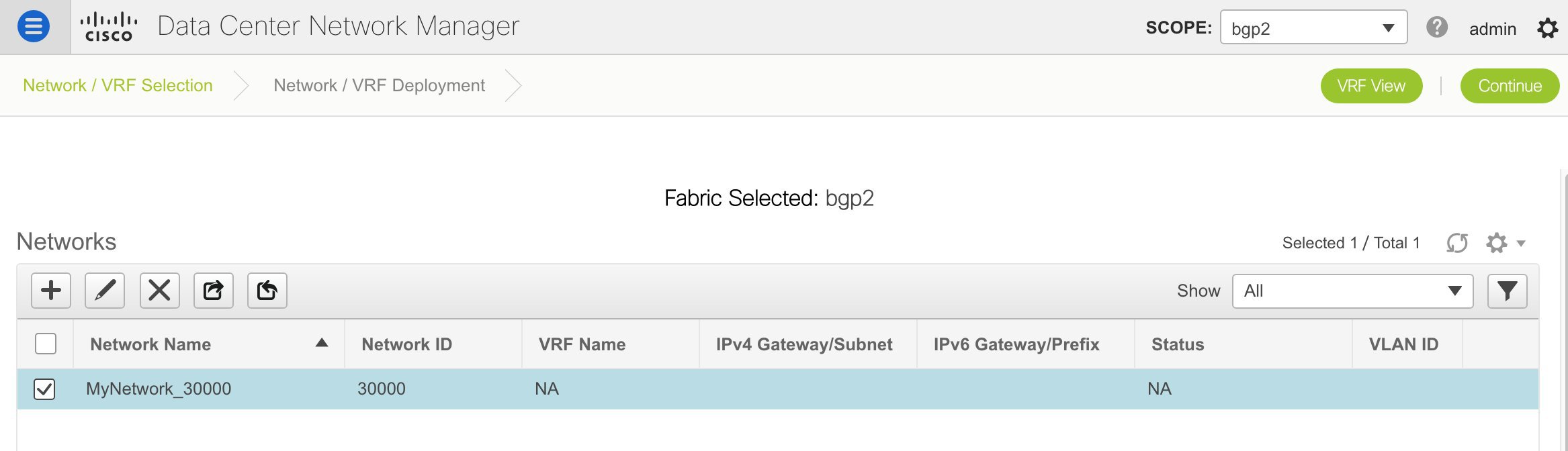
-
Select MSD-Parent-Fabric from the list and click Continue at the top right part of the screen.
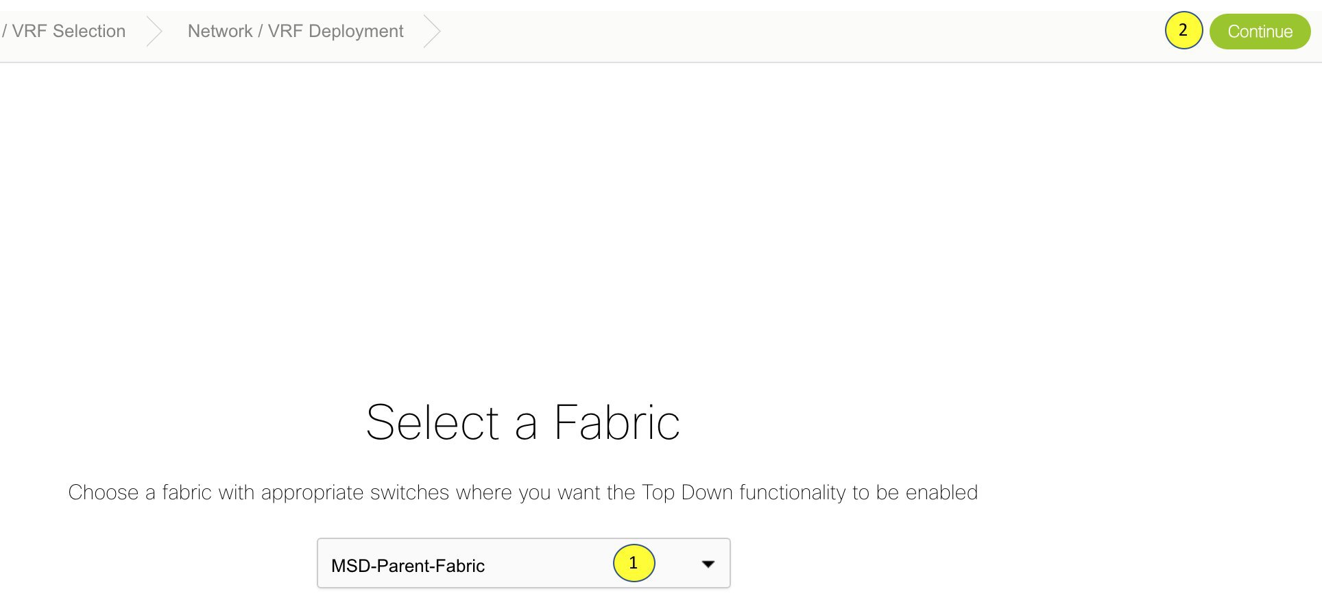
The Networks page comes up. This lists the list of networks created for the MSD fabric. Initially, this screen has no entries.
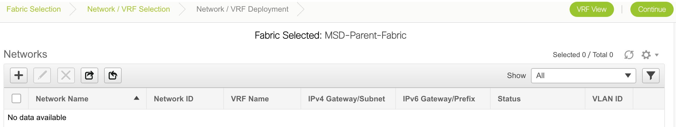
-
Click the + button at the top left part of the screen (under Networks) to add networks to the MSD fabric. The Create Network screen comes up. Most of the fields are autopopulated.
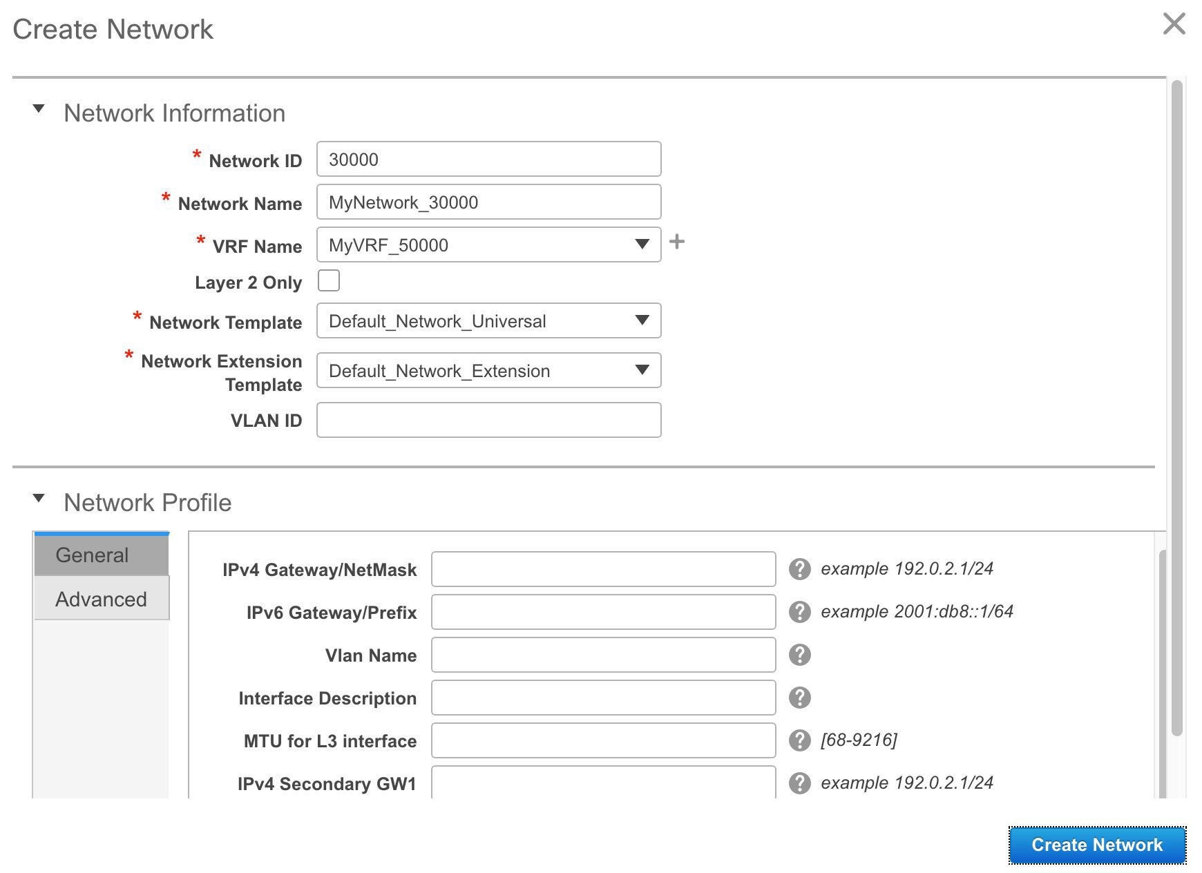
The fields in this screen are:
Network ID and Network Name - Specifies the Layer 2 VNI and name of the network. The network name should not contain any white spaces or special characters except underscore (_) and hyphen (-).
VRF Name - Allows you to select the Virtual Routing and Forwarding (VRF).
When no VRF is created, this field is blank. If you want to create a new VRF, click the + button. The VRF name should not contain any white spaces or special characters except underscore (_), hyphen (-), and colon (:).
Note
You can also create a VRF by clicking the VRF View button on the Networks page.
Layer 2 Only - Specifies whether the network is Layer 2 only.
Network Template - Allows you to select a network template.
Network Extension Template - This template allows you to extend the network between member fabrics.
VLAN ID - Specifies the corresponding tenant VLAN ID for the network.
Network Profile section contains the General and Advanced tabs, explained below.
General tab
IPv4 Gateway/NetMask - Specifies the IPv4 address with subnet.
IPv6 Gateway/Prefix - Specifies the IPv6 address with subnet.
VLAN Name - Enter the VLAN name.
If the VLAN is mapped to more than one subnet, enter the anycast gateway IP addresses for those subnets.
Interface Description - Specifies the description for the interface.
MTU for the L3 interface - Enter the MTU for Layer 3 interfaces.
IPv4 Secondary GW1 - Enter the gateway IP address for the additional subnet.
IPv4 Secondary GW2 - Enter the gateway IP address for the additional subnet.
Advanced tab - Optionally, specify the advanced profile settings by clicking the Advanced tab. The options are:
-
ARP Suppression
-
DHCPv4 Server 1 and DHCPv4 Server 2 - Enter the DHCP relay IP address of the first and second DHCP servers.
-
DHCPv4 Server VRF - Enter the DHCP server VRF ID.
-
Loopback ID for DHCP Relay interface - Enter the loopback ID of the DHCP relay interface.
-
Routing Tag – The routing tag is autopopulated. This tag is associated with each gateway IP address prefix.
-
TRM enable – Select the checkbox to enable TRM.
-
L2 VNI Route-Target Both Enable - Select the check box to enable automatic importing and exporting of route targets for all L2 virtual networks.
-
Enable L3 Gateway on Border - Select the checkbox to enable the Layer 3 gateway on the border device.
A sample of the Create Network screen:
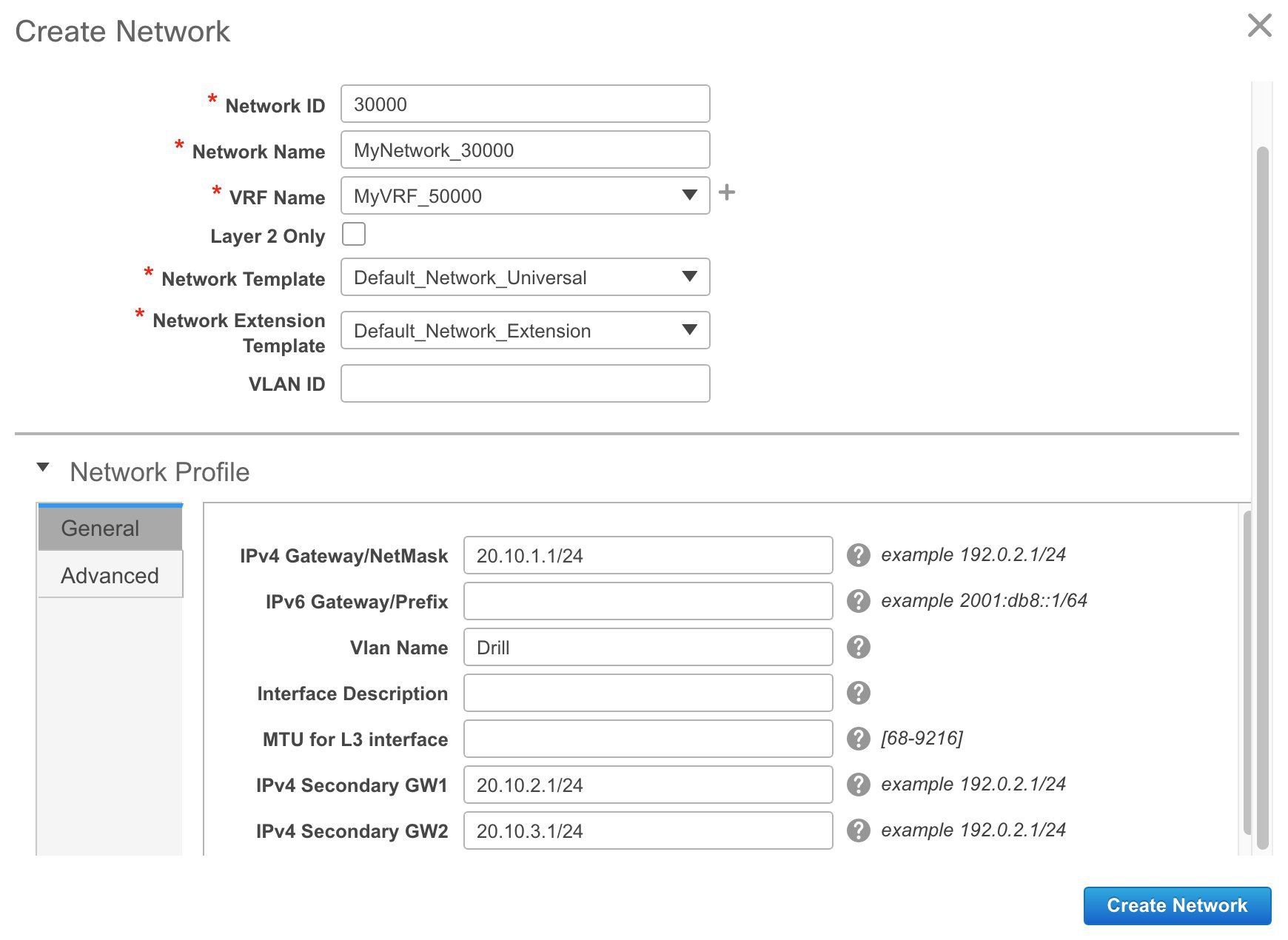
Advanced tab:
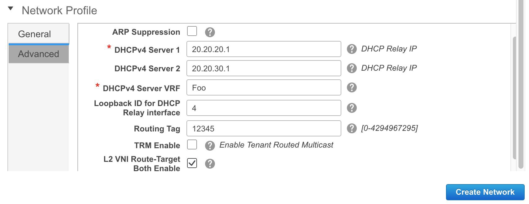
-
-
Click Create Network. A message appears at the bottom right part of the screen indicating that the network is created. The new network (MyNetwork_30000) appears on the Networks page that comes up.
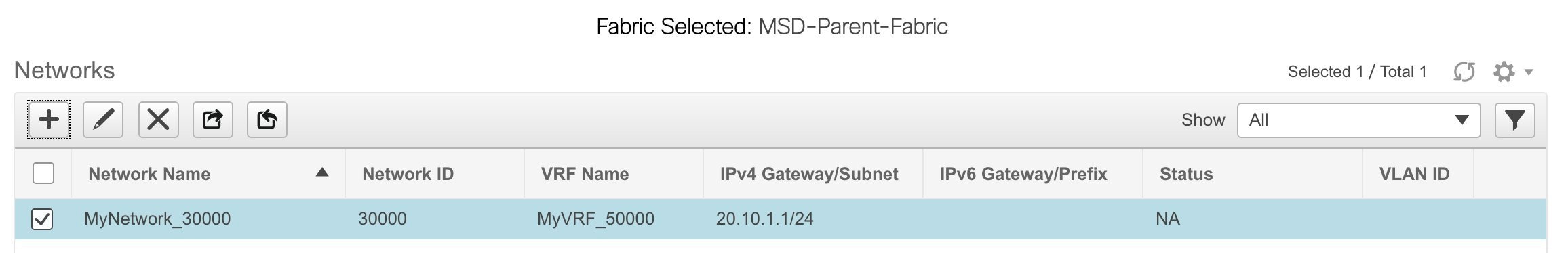
Editing Networks in the MSD Fabric
-
In the Networks screen of the MSD fabric, select the network you want to edit and click the Edit icon at the top left part of the screen.
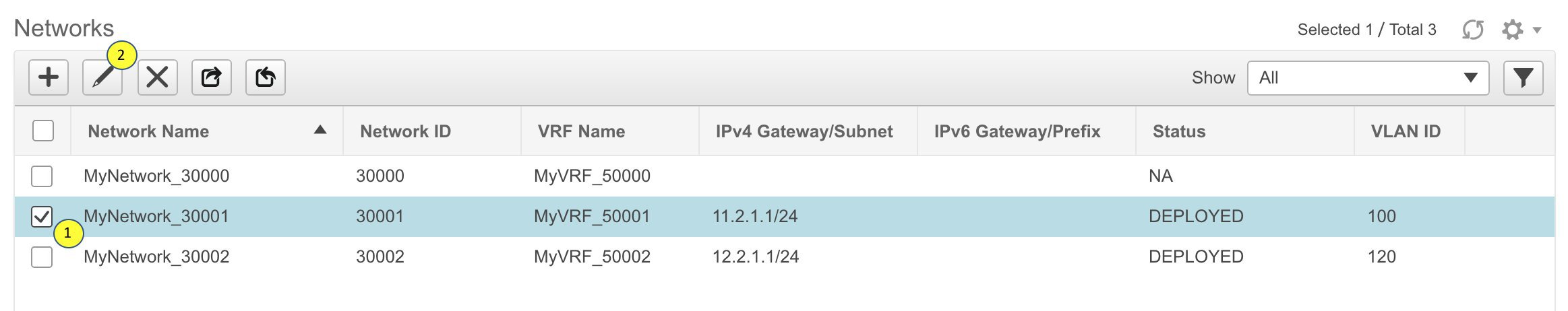
The Edit Network screen comes up.
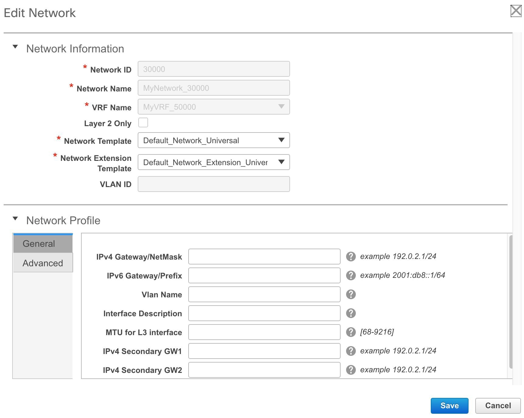
You can edit the Network Profile part (General and Advanced tabs) of the MSD fabric network.
-
Click Save at the bottom right part of the screen to save the updates.
Network Inheritance from MSD-Parent-Fabric to Member1
MSD-Parent-Fabric fabric contains one member fabric, Member1. Go to the Select a Fabric page to access the Member1 fabric.
-
Click Control > Networks (under Fabrics submenu).
The Networks screen comes up.
-
Choose the correct fabric from SCOPE. When you select a fabric, the Networks screen refreshes and lists networks of the selected fabric.
Editing Networks in the Member Fabric
An MSD can contain multiple fabrics. These fabrics forward BUM traffic via Multicast or Ingress replication. Even if all the fabrics use multicast for BUM traffic, the multicast groups within these fabrics need not be the same.
When you create a network in MSD, it is inherited by all the member fabrics. However, the multicast group address is a fabric instance variable. To edit the multicast group address, you need to navigate to the member fabric and edit the network. For more information about the Multicast Group Address field, see Creating Networks for the Standalone Fabric.
-
Select the network and click the Edit option at the top left part of the window. The Edit Network window comes up.
-
Update the multicast group address in one of the following ways:
-
Under Network Profile, click the Generate Multicast IP button to generate a new multicast group address for the selected network, and click Save.
-
Click the Advanced tab in the Network Profile section, update the multicast group address, and click Save.
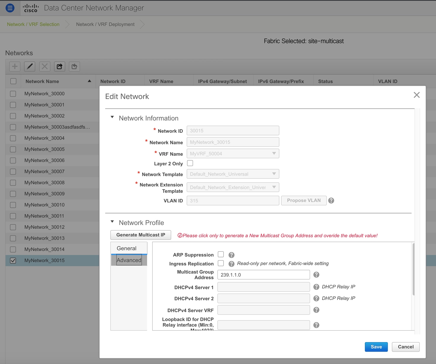
-
Note |
The Generate Multicast IP option is only available for member fabric networks and not MSD networks. |
Deleting Networks in the MSD and Member Fabrics
You can only delete networks from the MSD fabric, and not member fabrics. To delete networks and corresponding VRFs in the MSD fabric, follow this order:
-
Undeploy the networks on the respective fabric devices before deletion.
-
Delete the networks from the MSD fabric. To delete networks, use the delete (X) option at the top left part of the Networks screen. You can delete multiple networks at once.
Note
When you delete networks from the MSD fabric, the networks are automatically removed from the member fabrics too.
-
Undeploy the VRFs on the respective fabric devices before deletion.
-
Delete the VRFs from the MSD fabric by using the delete (X) option at the top left part of the screen. You can delete multiple VRF instances at once.
Creating VRFs in the MSD Fabric
-
From the MSD fabric's Networks page, click the VRF View button at the top right part of the screen to create VRFs.
-
Choose the correct fabric from SCOPE. When you select a fabric, the VRFs screen refreshes and lists VRFs of the selected fabric.
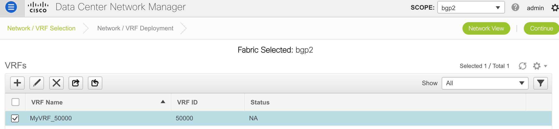
-
Choose the MSD fabric (MSD-Parent-Fabric) from the drop-down box and click Continue. The Networks page comes up.
-
Click VRF View at the top right part of the Networks page].
The VRFs page comes up. This lists the list of VRFs created for the MSD fabric. Initially, this screen has no entries.
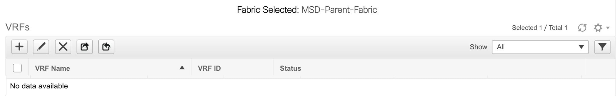
-
-
Click the + button at the top left part of the screen to add VRFs to the MSD fabric. The Create VRF screen comes up. Most of the fields are autopopulated.
The fields in this screen are:
VRF ID and VRF Name - The ID and name of the VRF.
The VRF ID is the VRF VNI or the L3 VNI of the tenant.
Note
For ease of use, the VRF creation option is also available while you create a network.
VRF Template - This is populated with the Default_VRF template.
VRF Extension Template - This template allows you to extend the VRF between member fabrics.
-
General tab – Enter the VLAN ID of the VLAN associated with the VRF, the corresponding Layer 3 virtual interface, and the VRF ID.
-
Advanced tab
Routing Tag – If a VLAN is associated with multiple subnets, then this tag is associated with the IP prefix of each subnet. Note that this routing tag is associated with overlay network creation too.
Redistribute Direct Route Map – Specifies the route map name for redistribution of routes in the VRF.
Max BGP Paths and Max iBGP Paths – Specifies the maximum BGP and iBGP paths.
TRM Enable – Select the checkbox to enable TRM.
If you enable TRM, then the RP address, the RP loopback ID and the underlay multicast address must be entered.
Is RP external - Select the checkbox if a fabric-external device is designated as RP.
RP Address and RP Loopback ID – Specifies the loopback ID and IP address of the RP.
Underlay Multicast Address – Specifies the multicast address associated with the VRF. The multicast address is used for transporting multicast traffic in the fabric underlay.
Overlay Multicast Groups – Specifies the multicast address for the VRF, used in the fabric overlay.
Enable IPv6 link-local Option - Select the checkbox to enable the IPv6 link-local option.
Advertise Host Routes - Select the checkbox to control advertisement of /32 and /128 routes to Edge Routers.
Advertise Default Route - Select the checkbox to control advertisement of default routes within the fabric.
A sample screenshot:
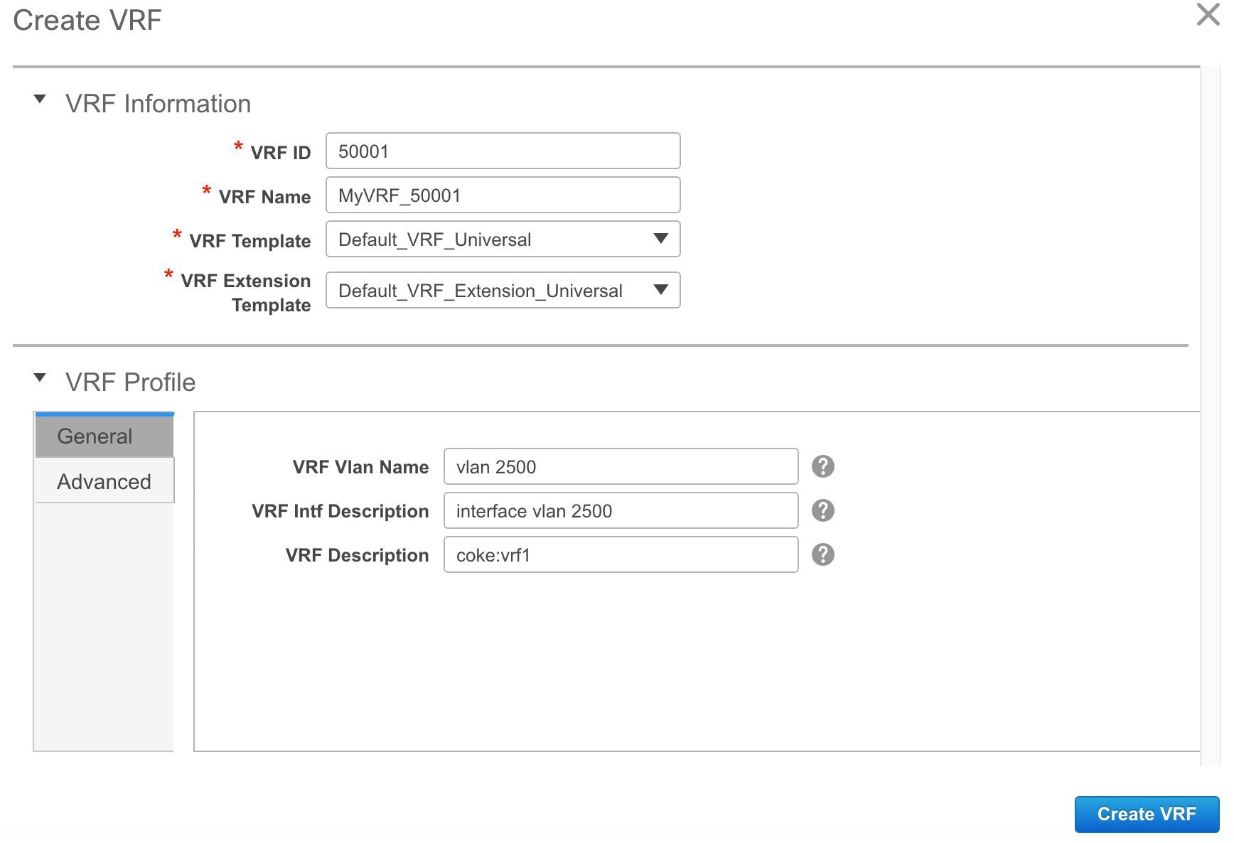
Advanced tab:
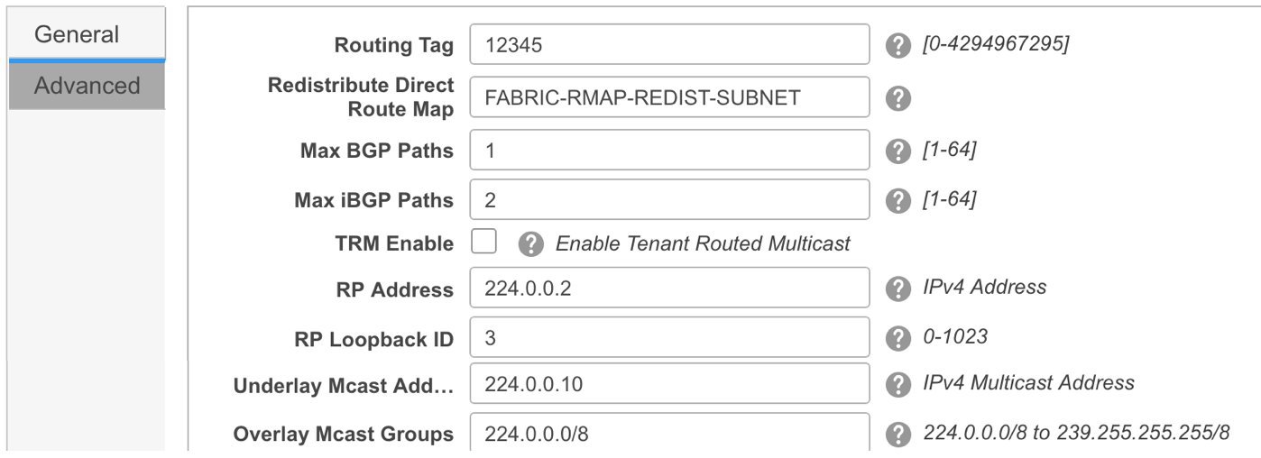
-
Click Create VRF.
The MyVRF_50000 VRF is created and appears on the VRFs page.
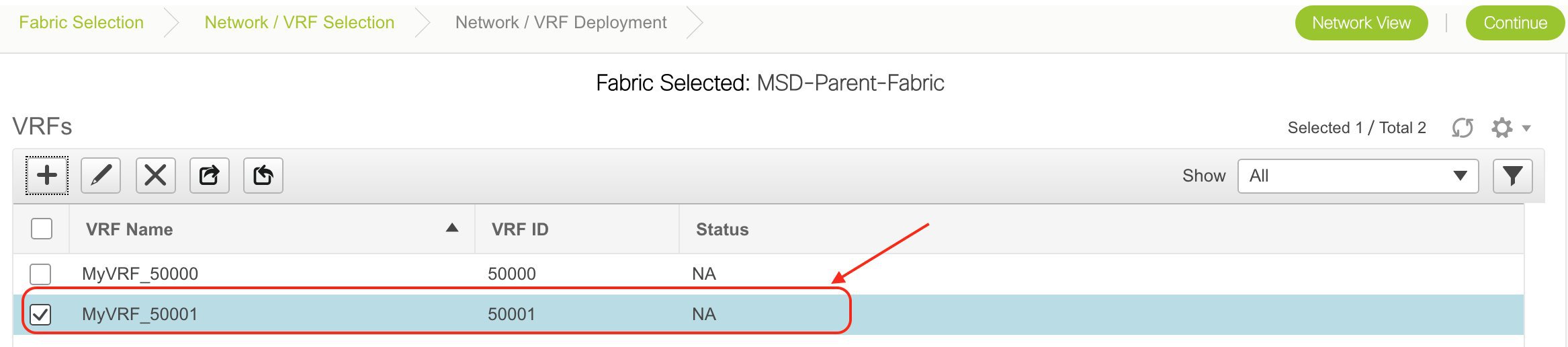
Editing VRFs in the MSD Fabric
-
In the VRFs screen of the MSD fabric, select the VRF you want to edit and click the Edit icon at the top left part of the screen.
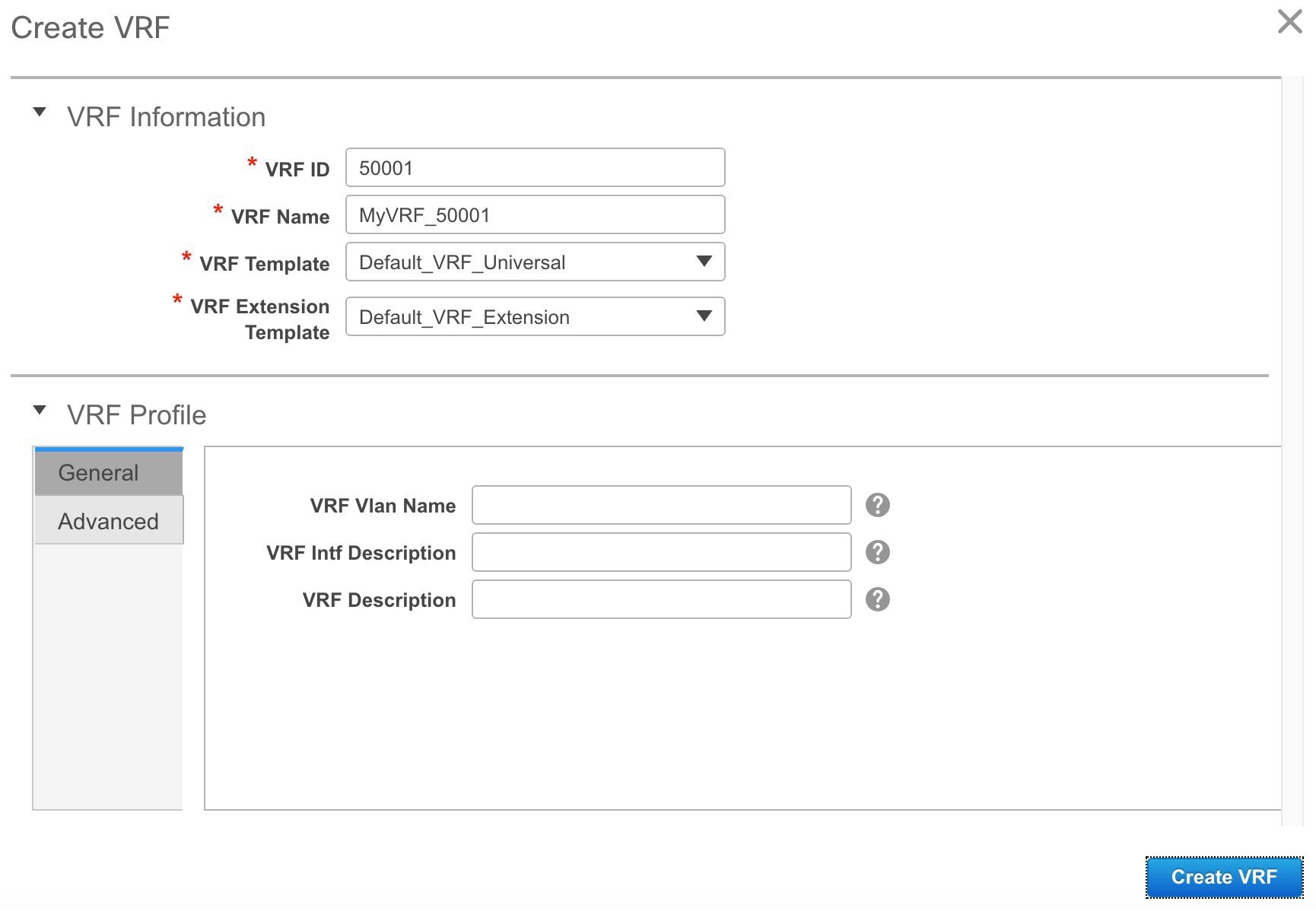
The Edit VRF screen comes up.
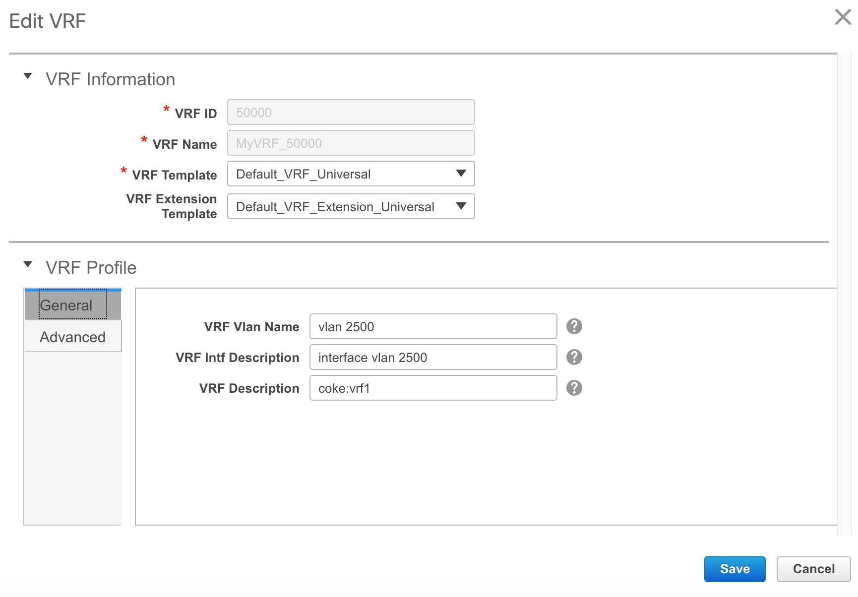
You can edit the VRF Profile part (General and Advanced tabs).
-
Click Save at the bottom right part of the screen to save the updates.
VRF Inheritance from MSD-Parent-Fabric to Member1
MSD-Parent-Fabric contains one member fabric, Member1. Do the following to access the member fabric page.
-
Choose the correct fabric from SCOPE. When you select a fabric, the VRFs screen refreshes and lists VRFs of the selected fabric.
-
Click the VRF View button. On the VRFs page, you can see that the VRF created for the MSD is inherited to its member.
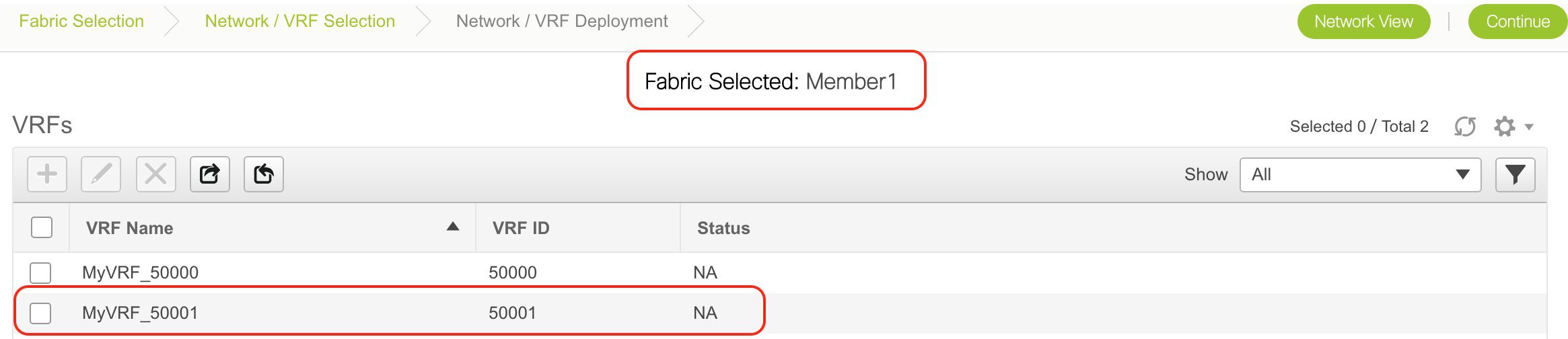
Deleting VRFs in the MSD and Member Fabrics
You can only delete networks from the MSD fabric, and not member fabrics. To delete networks and corresponding VRFs in the MSD fabric, follow this order:
-
Undeploy the networks on the respective fabric devices before deletion.
-
Delete the networks from the MSD fabric.
-
Undeploy the VRFs on the respective fabric devices before deletion.
-
Delete the VRFs from the MSD fabric by using the delete (X) option at the top left part of the screen. You can delete multiple VRF instances at once.
Note
When you delete VRFs from the MSD fabric, they are automatically removed from the member fabrics too.
Editing VRFs in the Member Fabric
You cannot edit VRF parameters at the member fabric level. Update VRF settings in the MSD fabric. All member fabrics are automatically updated.
Deleting VRFs in the Member Fabric
You cannot delete VRFs at the member fabric level. Delete VRFs in the MSD fabric. The deleted VRFs are automatically removed from all member fabrics.
Step 1 of the following is explained. Step 2 information is mentioned in the next subsection.
-
Create networks and VRFs in the MSD fabric.
-
Deploy the networks and VRFs in the member fabric devices, one fabric at a time.
Deployment and Undeployment of Networks and VRFs in Member Fabrics
Before you begin, ensure that you have created networks at the MSD fabric level since the member fabric inherits networks and VRFs created for the MSD fabric.
Note |
The deployment (and undeployment) of networks and VRFs in member fabrics are the same as explained for standalone fabrics. Refer the standalone fabric documentation (Networks Deployment and VRFs Deployment sections in the Networks and VRFs Creation and Deployment in a Standalone Fabric topic). |
Removing a Fabric From an MSD
To remove a fabric from an MSD fabric, perform the following steps:
Before you begin
Procedure
| Step 1 |
From the Fabric Builder window, click an MSD fabric. |
| Step 2 |
Click Move Fabric in the Actions menu. |
| Step 3 |
In the Move Fabric window, select the respective radio button of the fabric that you want to remove and click Remove. In the fabric removal notification window, click Close. |
| Step 4 |
Click Save & Deploy for the MSD in the Fabric Builder window. |
| Step 5 |
Click Deploy Config in the Config Deployment window. Click Close. |
| Step 6 |
Navigate to the fabric that you removed from MSD and click Save & Deploy. |
| Step 7 |
Click Deploy Config in the Config Deployment window. Click Close. |
Moving a Standalone Fabric (With Existing Networks and VRFs) to an MSD Fabric
If you move a standalone fabric with existing networks and VRFs to an MSD fabric as a member, ensure that common networks (that is, L2 VNI and L3 VNI information), anycast gateway MAC, and VRF and network templates are the same across the fabric and the MSD. DCNM validates the standalone fabric (network and VRF information) against the (network and VRF information) of the MSD fabric to avoid duplicate entries. An example of duplicate entries is two common network names with a different network ID. After validation for any conflicts, the standalone fabric is moved to the MSD fabric as a member fabric. Details:
-
The MSD fabric inherits the networks and VRFs of the standalone fabric that do not exist in the MSD fabric. These networks and VRFs are in turn inherited by the member fabrics.
-
The newly created member fabric inherits the networks and VRFs of the MSD fabric (that do not exist in the newly created member fabric).
-
If there are conflicts between the standalone and MSD fabrics, validation ensures that an error message is displayed. After the updation, when you move the member fabric to the MSD fabric, the move will be successful. A message comes up at the top of the page indicating that the move is successful.
If you move back a member fabric to standalone status, then the networks and VRFs remain as they are, but they remain relevant as in an independent fabric, outside the purview of an MSD fabric.
Switch Operations
You can right-click the switch to view various options:
-
Set Role - Assign a role to the switch. You can assign any one of the following roles to a switch:
-
Spine
-
Leaf (Default role)
-
Border
-
Border Spine
-
Border Gateway
-
Border Gateway Spine
-
Note |
|
Starting from DCNM 11.1(1), you can change switch roles if there are no overlays on the switches. The updated configuration is then generated after you click Save and Deploy. The following switch role changes are allowed:
-
Leaf to Border
-
Border to Leaf
-
Leaf to Border Gateway
-
Border Gateway to Leaf
-
Border to Border Gateway
-
Border Gateway to Border
-
Spine to Border Spine
-
Border Spine to Spine
-
Spine to Border Gateway Spine
-
Border Gateway Spine to Spine
-
Border Spine to Border Gateway Spine
-
Border Gateway Spine to Border Spine
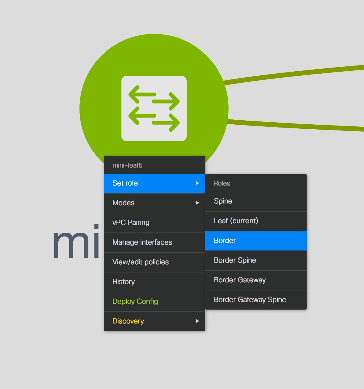
Changing of switch role from any Leaf role to any Spine role and from any Spine role to any Leaf role is not allowed.
Switch[<serial-number>]: Role change from <switch-role> to <switch-role> is not permitted.
You can then change the switch role to the role that was set earlier, or set a new role that adheres to the rules mentioned above, and configure the fabric.
If you have not created any policy template instances before clicking Save and Deploy, and there are no overlays, you can change the role of a switch to any other required role.
Switches role should be the same for VPC pairing. peer1 <serial-number>: [<switch-role>], peer2 <serial-number>: [<switch-role>]
To prevent this scenario, change the switch roles of both the switches in the vPC pair to the same role.
Fabric Multi Switch Operations
In the fabric topology screen, click Tabular view option in the Actions panel, at the left part of the screen. The Switches | Links screen comes up.
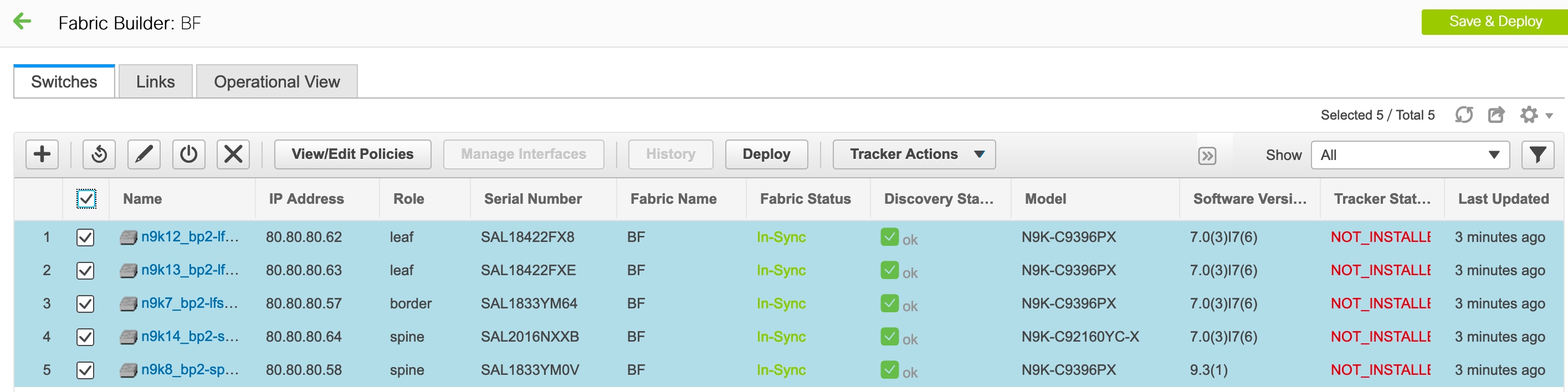
The Switches tab is for managing switch operations and the Links tab is for adding and updating fabric links. Each row represents a switch in the fabric, and displays switch details, including its serial number.
The buttons at the top of the table are explained, from left to right direction. Some options are also available when you right-click the switch icon. However, the Switches tab enables you to provision configurations on multiple switches (for example, adding and deploying policies) simultaneously.
-
Add switches to the fabric. This option is also available in the topology page (Add switches option in Actions panel).
-
Initiate the switch discovery process by DCNM afresh.
-
Update device credentials such as authentication protocol, username and password.
-
Reload the switch.
-
Remove the switch from the fabric.
-
View/Edit Policies: Add, update and delete a policy. The policies are template instances of templates in the template library. After creating a policy, you should deploy it on the switches using the Deploy option available in the View/edit Policies screen. You can select more than one policy and view them.
Note
If you select multiple switches and deploy a policy instance, then it will be deployed on all the selected switches.
-
Manage Interfaces: Deploy configurations on the switch interfaces.
-
History: View deployment history on the selected switch.
-
Deploy: Deploy switch configurations. From Cisco DCNM Release 11.3(1), you can deploy configurations for multiple devices using the Deploy button.
Note
In an MSD fabric, you can deploy configurations only on the Border Gateway, Border Gateway Spine, Border Gateway Super-Spine, or External Fabric switches.
Fabric Links
You can add links between border switches of different fabrics (inter-fabric links) or between switches in the same fabric (intra-fabric links). You can only create an inter-fabric connection (IFC) for a switch that is managed by DCNM.
There are scenarios where you might want to define links between switches before connecting them physically. The links could be inter-fabric or intra-fabric links. Doing so, you can express and represent your intent to add links. The links with intent are displayed in a different colour till they are actually converted to functional links. Once you physically connect the links, they are displayed as connected.
Management links might show up in the fabric topology as red colored links. To remove such links, right-click the link and click Delete Link.
From Cisco DCNM Release 11.1(1), the Border Spine and Border Gateway Spine roles are added to switch roles for border switches.
You can create links between existing and pre-provisioned devices as well by selecting the pre-provisioned device as the destination device.
Creating Intra-Fabric Links
-
Click Control > Fabric Builder to go to the Fabric Builder screen.
-
Click within the rectangular box that represents the fabric. The fabric topology screen comes up.
-
Click Tabular view in the Actions panel that is displayed at the left part of the screen.
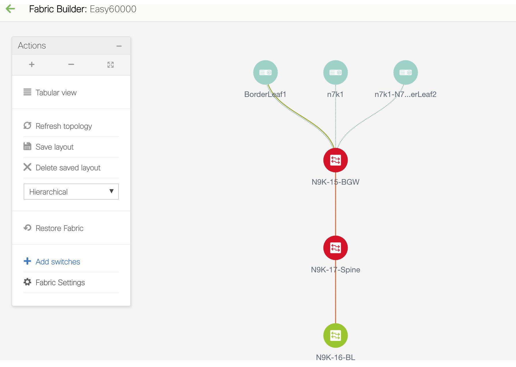
A screen with the tabs Switches and Links appears. They list the fabric switches and links in a table.
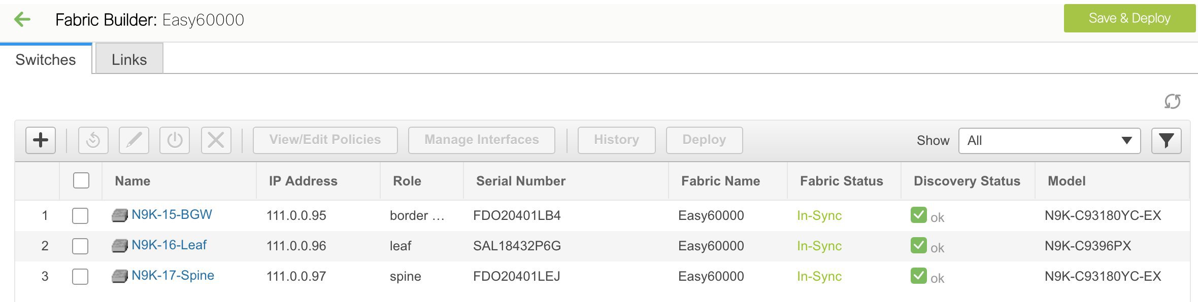
-
Click the Links tab. You can see a list of links.
The list is empty when you are yet to create a link.
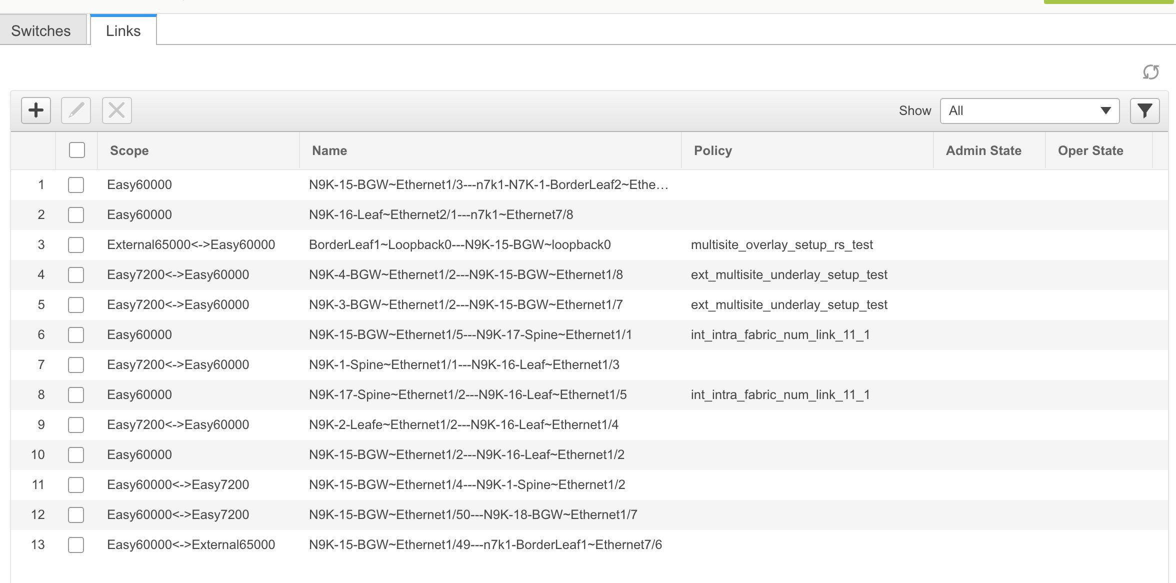
-
Click the Add (+) button at the top left part of the screen to add a link.
The Add Link screen comes up. By default, the Intra-Fabric option is chosen as the link type.
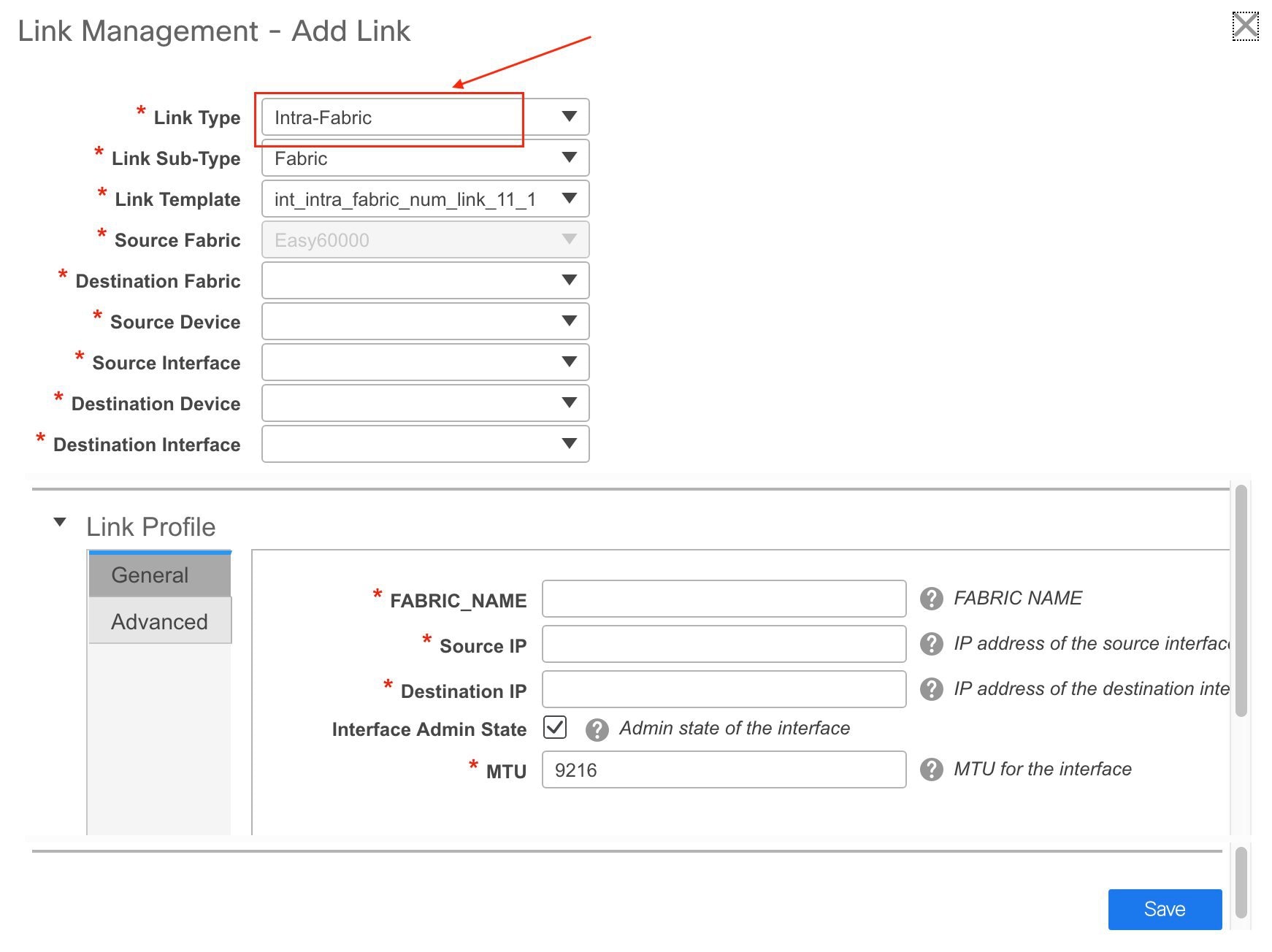
The fields are:
Link Type – Choose Intra-Fabric to create a link between two switches in a fabric.
Link Sub-Type – This field populates Fabric indicating that this is a link within the fabric.
Link Template: You can choose any of the following link templates.
-
int_intra_fabric_num_link_11_1: If the link is between two ethernet interfaces assigned with IP addresses, choose int_intra_fabric_num_link_11_1.
-
int_intra_fabric_unnum_link_11_1: If the link is between two IP unnumbered interfaces, choose int_intra_fabric_unnum_link_11_1.
-
int_intra_vpc_peer_keep_alive_link_11_1: If the link is a vPC peer keep-alive link, choose int_intra_vpc_peer_keep_alive_link_11_1.
-
int_pre_provision_intra_fabric_link: If the link is between two pre-provisioned devices, choose int_pre_provision_intra_fabric_link. After you click Save & Deploy, an IP address is picked from the underlay subnet IP pool.
Correspondingly, the Link Profile section fields is updated.
Source Fabric – The fabric name populates this field since the source fabric is known.
Destination Fabric – Choose the destination fabric. For an intra-fabric link, source and destination fabrics are the same.
Source Device and Source Interface – Choose the source device and interface.
Destination Device and Destination Interface – Choose the destination device and interface.
Note
Select the pre-provisioned device as the destination device if you are creating a link between an existing device and a pre-provisioned device.
General tab in the Link Profile section
Interface VRF – Name of a non-default VRF for this interface.
Source IP and Destination IP – Specify the source and destination IP addresses of the source and destination interfaces, respectively.
Note
The Source IP and Destination IP fields do not appear if you choose int_pre_provision_intra_fabric_link template.
Interface Admin State – Check or uncheck the check box to enable or disable the admin sate of the interface.
MTU – Specify the maximum transmission unit (MTU) through the two interfaces.
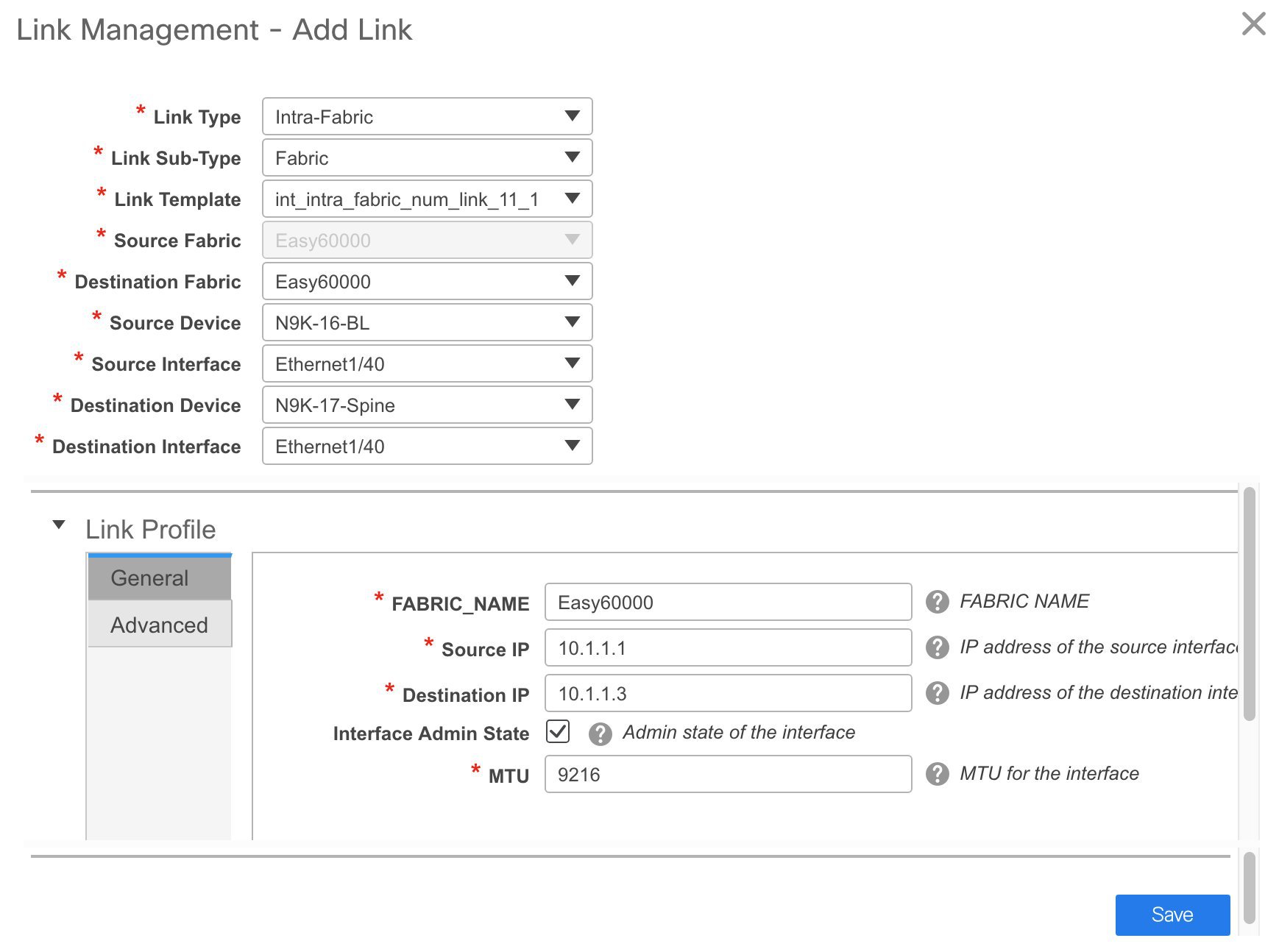
Advanced tab.
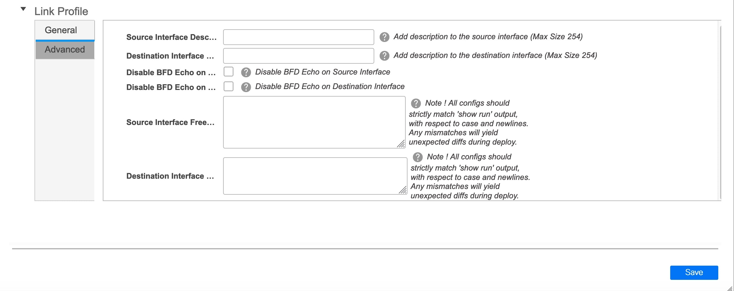
Source Interface Description and Destination Interface Description – Describe the links for later use. For example, if the link is between a leaf switch and a route reflector device, you can enter the information in these fields (Link from leaf switch to RR 1 and Link from RR 1 to leaf switch). This description will converted into a config, but will not be pushed into the switch. After Save & Deploy, it will reflect in the running configuration.
Disable BFD Echo on Source Interface and Disable BFD Echo on Destination Interface – Select the check box to disable BFD echo packets on source and destination interface.
Note that the BFD echo fields are applicable only when you have enabled BFD in the fabric settings.
Source Interface Freeform CLIs and Destination Interface Freeform CLIs: Enter the freeform configurations specific to the source and destination interfaces. You should add the configurations as displayed in the running configuration of the switch, without indentation. See Freeform Configurations on Fabric Switches section for a detailed explanation and examples.
-
-
Click Save at the bottom right part of the screen.
The new link appears in the Links tab.
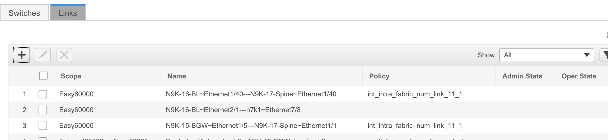
-
Click Save & Deploy to deploy the link configurations on the switches.
The Config Deployment screen comes up. It displays the configuration status on the switches. You can also view the pending configurations by clicking the respective link in the Preview Config column. When you click a link in the Preview Config column, the Config Preview window comes up. It lists the pending configurations on the switch. The Side-by-side Comparison tab displays the running configuration and expected configuration side-by-side.
-
Close the preview screen and click Deploy Config. The pending configurations are deployed.
-
After ensuring that the progress is 100% in all the rows, click Close at the bottom part of the screen. The Links screen comes up again.
Click <- at the top left part of the screen to go to the fabric topology. In the fabric topology, you can see that the link between the two devices is displayed.
Creating Inter-Fabric Links
-
Click the Links tab in the Switches | Links page. The list of previously created links are displayed. The list contains intra-fabric links (between switches in a fabric), and inter-fabric links (between BGWs or border leaf/spine switches of different fabrics).
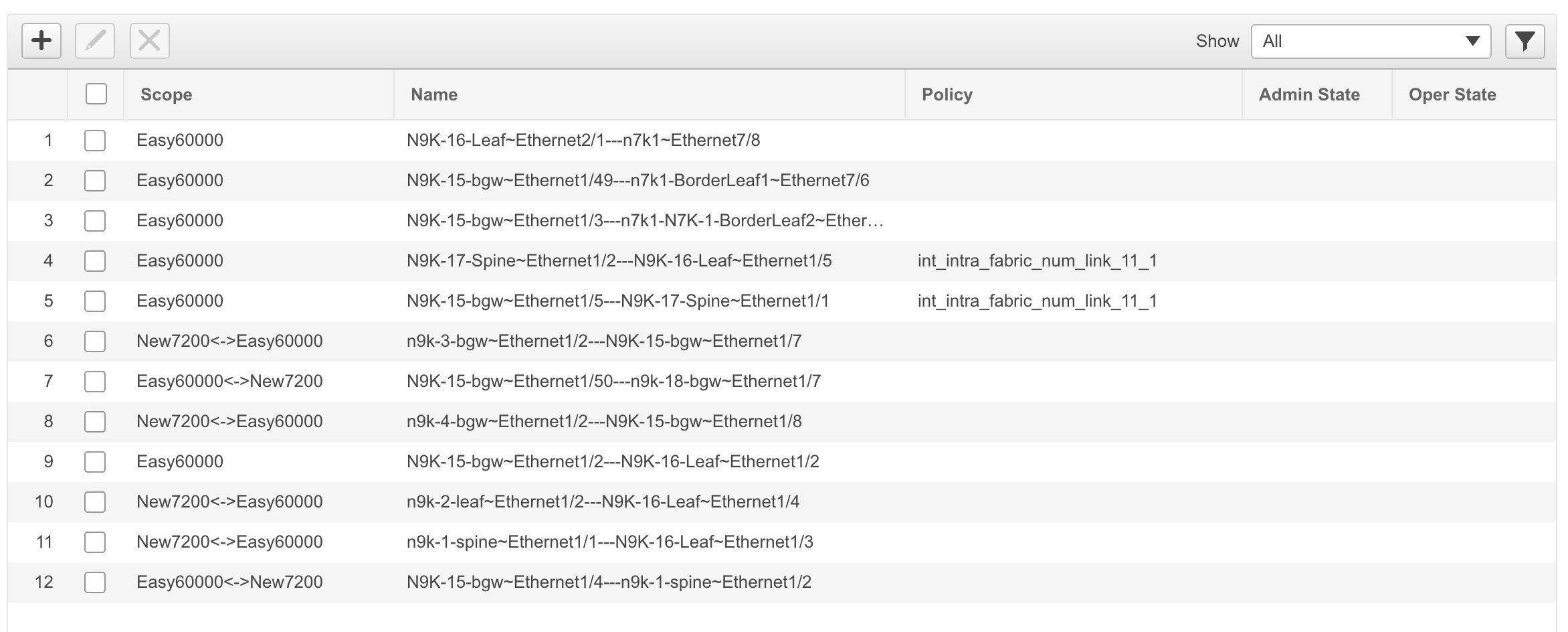
-
Click the Add (+) button at the top left part of the screen to add a link. The Add Link screen comes up.
By default, the Intra-Fabric option is chosen as the link type.
-
From the Link Type drop-down box, choose Inter-Fabric since you are creating an IFC. The screen changes correspondingly.
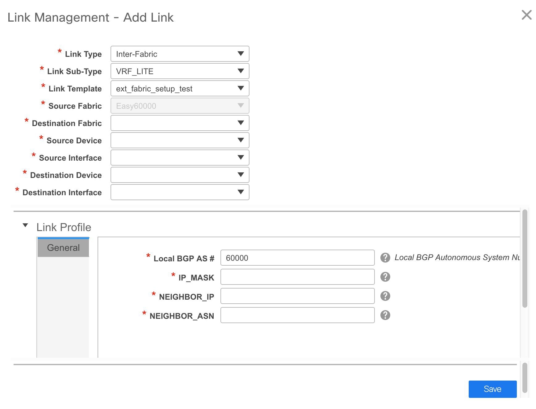
The fields for inter-fabric link creation are explained:
Link Type – Choose Inter-Fabric to create an inter-fabric connection between two fabrics, via their border switches.
Link Sub-Type – This field populates the IFC type. Choose VRF_LITE, MULTISITE_UNDERLAY, or MULTISITE_OVERLAY from the drop-down list.
The Multi-Site options are explained in the Multi-Site use case.
For information about VXLAN MPLS interconnection, see Border Provisioning Use Case in VXLAN BGP EVPN Fabrics - MPLS SR and LDP Handoff.
For information about routed fabric interconnection, see Creating Inter-Fabric Links Between a Routed Fabric and an External Fabric.
Link Template: The link template is populated.
The templates are autopopulated with corresponding pre-packaged default templates that are based on your selection.
Note
You can add, edit, or delete user-defined templates. See Template Library section in the Control chapter for more details.
Source Fabric - This field is prepopulated with the source fabric name.
Destination Fabric - Choose the destination fabric from this drop-down box.
Source Device and Source Interface - Choose the source device and Ethernet interface that connects to the destination device.
Destination Device and Destination Interface—Choose the destination device and Ethernet interface that connects to the source device.
Based on the selection of the source device and source interface, the destination information is autopopulated based on Cisco Discovery Protocol information, if available. There is an extra validation performed to ensure that the destination external device is indeed part of the destination fabric.
General tab in the Link Profile section.
Local BGP AS# - In this field, the AS number of the source fabric is autopopulated.
IP_MASK—Fill up this field with the IP address of the source interface that connects to the destination device.
NEIGHBOR_IP—Fill up this field with the IP address of the destination interface.
NEIGHBOR_ASN—In this field, the AS number of the destination device is autopopulated.
After filling up the Add Link screen, it looks like this:
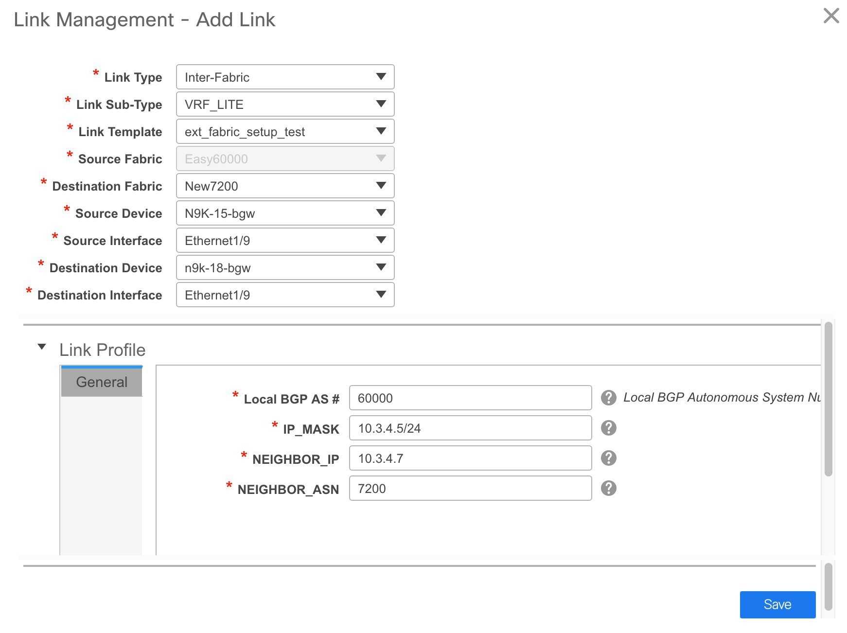
-
Click Save at the bottom right part of the screen.
The Switches|Links screen comes up again. You can see that the IFC is created and displayed in the list of links.
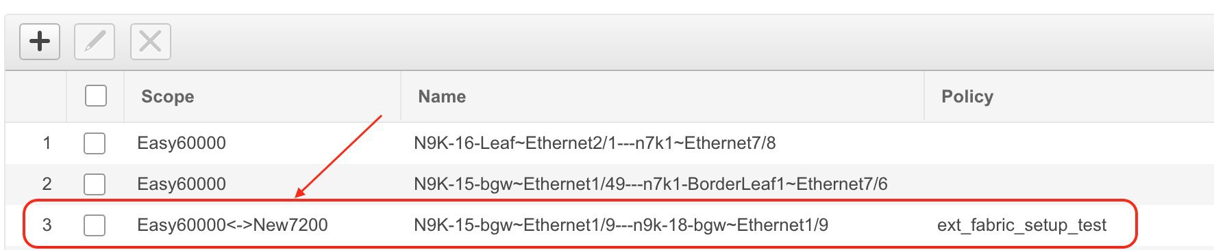
-
Click on Save & Deploy to deploy the link configurations on the switches.
The Config Deployment screen comes up. It displays the configuration status on the switches. You can also view the pending configurations by clicking the respective link in the Preview Config column. When you click a link in the Preview Config column, the Config Preview window comes up. It lists the pending configurations on the switch. The Side-by-side Comparison tab displays the running configuration and expected configuration side-by-side.
-
Close the preview screen and click Deploy Config. The pending configurations are deployed.
-
After ensuring that the progress is 100% in all the rows, click Close at the bottom part of the screen. The Links screen comes up again.
-
Click <- at the top left part of the screen to go to the fabric topology. In the fabric topology, you can see that the link between the two devices is displayed.
If the two fabrics are member fabric of an MSD, then you can see the link in the MSD topology too.
When you enable the VRF Lite function using the ToExternalOnly method or Multisite function via MSD fabric, IFCs are automatically created between the (VXLAN fabric) border/BGW device and connected (external fabric) edge router/core device. When you remove the ER/core/border/BGW device, the corresponding IFCs (link PTIs) to/from that switch are deleted on DCNM. Subsequently, DCNM removes the corresponding IFC configurations, if any, from the remaining devices on the next Save & Deploy operation. Also, if you want to remove a device that has an IFCs and overlay extensions over those IFCs, you should undeploy all overlay extensions corresponding to those IFCs for switch delete to be possible.
To undeploy VRF extensions, click Control > Networks & VRFs, select the VXLAN fabric and the extended VRFs, and undeploy the VRFs in the VRF deployment screen.
To delete the IFCs, click Control > Fabric Builder, go to the fabric topology screen, click Tabular view, and delete the IFCs from the Links tab.
Ensure that the fabric switch names are unique. If you deploy VRF extensions on switches with the same name, it leads to erroneous configuration.
The new fabric is created, the fabric switches are discovered in DCNM, the underlay networks provisioned on those switches, and the configurations between DCNM and the switches are synced. The remaining tasks are:
-
Provision interface configurations such as vPCs, loopback interface, and subinterface configurations.
-
Create overlay networks and VRFs and deploy them on the switches. [Networks and VRFs Creation and Deployment section.
Exporting Links
-
Choose , and select a fabric.
The fabric topology window appears.
-
Click Tabular view in the Actions panel.
A window with the Switches and Links tabs appears.
-
Click the Links tab.
You can see a list of links. The list is empty when you are yet to create a link.
-
Click the Export Links icon to export the links in a CSV file.
The following details of links are exported: link template, source fabric, destination fabric, source device, destination device, source switch name, destination switch name, source interface, destination interface, and nvPairs. The nvPairs field consits JSON object.
Importing Links
You can import a CSV file containing details of links to add new links to the fabric. The CSV file should have the following details of links: link template, source fabric, destination fabric, source device, destination device, source switch name, destination switch name, source interface, destination interface, and nvPairs.
Note |
|
-
Choose , and select a fabric.
The fabric topology window appears.
-
Click Tabular view in the Actions panel.
A window with the Switches and Links tabs appears.
-
Click the Links tab.
You can see a list of links. The list is empty when you are yet to create a link.
-
Click the Import Links icon.
The file server directory opens.
-
Browse the directory and select the CSV file that you want to import.
-
Click Open.
A confirmation screen appears.
-
Click Yes to import the selected file.
Viewing Details of Fabric Links
Procedure
| Step 1 |
Choose Control > Fabrics > Fabric Builder and select a fabric. The topology view of the fabric appears. |
||
| Step 2 |
Double-click any of the links. The details window appears. You can view the devices that are connected using this link, summary, and the data traffic. |
||
| Step 3 |
Click Show more details. A comparison table of the two devices connected by the link appears. It includes the following parameters of the devices: device name, name, admin status, operation status, reason, policies, overlay network, status, PC, vPC ID, speed, MTU, mode, VLANs, IP or prefix, VRF, neighbor, and description.
|
||
| Step 4 |
Click the Back icon to go back to the details window.
|
Viewing the Traffic Details of Fabric Links
In the details window of a fabric link, you can choose how you want to view the traffic details. You can view the traffic details based on the time duration, format, and export this information.
You can view the data traffic of a link for the following durations from the duration drop-down list:
-
24 Hours
-
Week
-
Month
-
Year
Show: Click Show, and choose Chart, Table, or Chart and Table from the drop-down list to see how you want to view the traffic details. Enlarge your browser window to view the details in Chart and Table format.
If you choose Chart, hover over the traffic chart to view the Rx and Tx values, along the Y axis, for the corresponding time, along X axis. You can change the time duration values of the X axis by moving the sliders in the time range selector. You can choose the Y-axis values by checking or unchecking the Rx and Tx check boxes.
Note |
If you select Week, Month, or Year as the time duration, you can also view the Peak Rx and Peak Tx values along the Y axis. |
Select Table to view the traffic information in tabular format.
Chart Type and Chart Options: Choose Area Chart or Line Chart from the Chart Type drop-down list.
You can choose the following chart options:
-
Show Fill Patterns
-
Show Datamarkers
-
Y Axis Log Scale
Actions: Export or print the traffic information by choosing the appropriate options from the Actions drop-down list.
Symmetric Automatic VRF Lite
-
Check the Auto Deploy Flag check box in the Link Management dialog box. Checking this check box enables VRF lite deployment on both ends of the link for managed devices.
-
When you extend the VRF lite in a back-to-back scenario, the VRF should already be present in the peer fabric and the VRF name should be the same. An error message appears if the VRF is not present in the peer fabric and if you try to extend the VRF lite.
-
When you extend the VRF lite between an easy fabric and an external fabric, the VRF name can be the same as that of the source fabric, default, or another VRF name. However, the child PTIs for the subinterface and the VRF creation or peering on the external fabric has the source. Hence, you cannot edit or delete the policies from the View/Edit policies window.
-
Besides the IPv6 address, enter the IP mask, IPv4 address, and the neighbor IP address as well to deploy VRF from topdown using symmetric VRF lite.
-
Deploy configurations in both the fabrics.
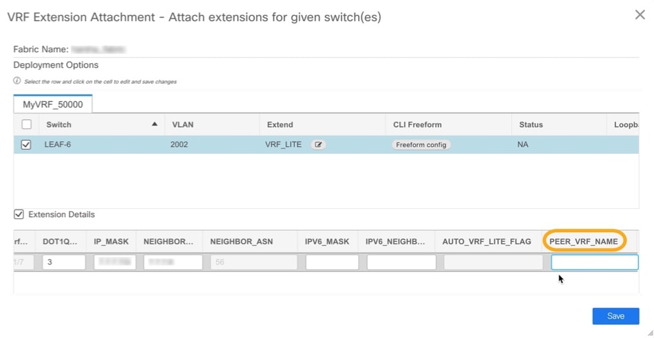
-
You can edit or delete IFCs in the Link tab in the VXLAN fabric. The extra consideration for auto configured IFCs is that, in order to prevent the regeneration of IFC on next save and deploy, change the mode back to manual mode, or save the configuration only on the relevant devices.
-
In a back-to-back scenario, if you delete the VRF lite IFC on one of the fabrics, the VRF lite is deleted from the peer fabric as well.
-
When you want to delete a VRF lite between an easy fabric and an external fabric, delete the extension in the easy fabric using the top-down approach. The extension is automatically deleted from the external fabric.
-
Deploy the configurations in both the fabrics.
See the Border Provisioning Use Case in VXLAN BGP EVPN Fabrics - VRF Lite chapter for a use case on VRF Lite.
Layer 3 Port Channels
From Cisco DCNM Release 11.3(1), Layer 3 port channels are supported in external links and interfaces. In the Interfaces window, you can select a port channel and a corresponding Layer 3 port channel interface template. This template allows you to configure various options related to Layer 3 port channels including an ability to specify all Layer 3 interface-related configurations. Layer 3 port channels are supported only in easy fabrics and external fabrics.
External connectivity using VRF_LITE will also be supported using Layer 3 port-channels. For physical routed interfaces and LAYER 3 port channel interfaces, you can set the MTU.
Configuring Layer 3 Port Channel on Interfaces
To configure a Layer 3 port channel on an interface from the Cisco DCNM Web UI, perform the following steps:
Procedure
| Step 1 |
Choose Control > Fabrics > Interfaces. The Interfaces window appears. |
| Step 2 |
Click Add Interface. The Add Interface dialog box appears. |
| Step 3 |
Choose the Port Channel type and a device. The port-channel ID is autopopulated. |
| Step 4 |
Choose the int_l3_port_channel policy. The fields under the General area changes accordingly. |
| Step 5 |
Enter the values in the fields and click Save. Only saved configurations are pushed to the device. While adding the interface, you can only modify the policy attribute after the first save. If you try to use an ID that is already used, the Resource could not be allocated error appears. |
| Step 6 |
(Optional) Click the Preview option to preview the configurations to be deployed. |
| Step 7 |
Click Deploy to deploy the specified logical interface. The newly added interface appears in the screen. You can break out and unbreakout an interface by using the breakout option at the top left. |
Configuring Layer 3 Port Channel on Subinterfaces
To configure a Layer 3 port channel on an interface from the Cisco DCNM Web UI, perform the following steps:
Procedure
| Step 1 |
Choose Control > Fabrics > Interfaces. The Interfaces window appears. |
| Step 2 |
Choose a Layer 3 port channel interface. |
| Step 3 |
Click Add Interface. The Add Interface dialog box appears. |
| Step 4 |
Choose the Subinterface type. The subinterface ID and policy are autopopulated, and the fields under the General area changes accordingly. |
| Step 5 |
Enter the values in the fields and click Save. Only saved configurations are pushed to the device. |
| Step 6 |
(Optional) Click the Preview option to preview the configurations to be deployed. |
| Step 7 |
Click Deploy to deploy the specified logical interface. A confirmation window appears, and the newly added subinterface appears in the list. |
Configuring Layer 3 Port Channel for Inter-fabric Connectivity
To configure a Layer 3 port channel link from the Fabric Builder window, perform the following steps:
Before you begin
Procedure
| Step 1 |
Choose an easy fabric or an external fabric, for which you want to extend the VRF-Lite. The fabric topology window appears. |
| Step 2 |
Click Tabular view in the Actions pane. All the components of this fabric are listed with their status and other details accordingly in different tabs. |
| Step 3 |
Choose the Links tab. |
| Step 4 |
Click the Add Link icon. The Add Link dialog box appears. |
| Step 5 |
Choose Inter-Fabric link type. |
| Step 6 |
Choose VRF_LITE link sub-type. |
| Step 7 |
Choose the link template from the Link Template drop-down list. Valid values are ext_fabric_setup_11_1 and service_link_trunk. |
| Step 8 |
Enter the details for all other fields accordingly. |
| Step 9 |
Enter the details for fields in the Link Profile area wherever necessary. You can set the MTU. The Ext_VRF_Lite_Jython auto-deploy template is used for VRF-Lite configuration on the device in the fabric. |
| Step 10 |
Click Save.
|
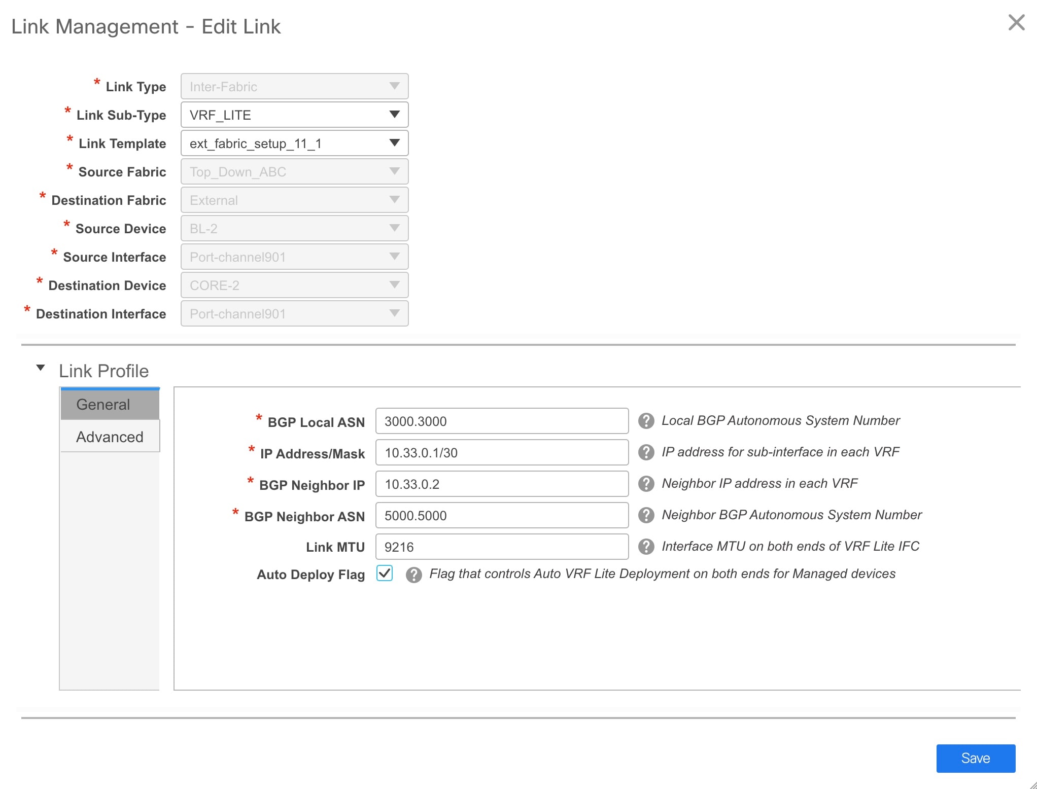
What to do next
Operational Support for a Fabric
From Cisco DCNM 11.3(1), the operational support for a fabric is provided. This feature provides the following information:
-
Operational status of a fabric
-
Alarm and event notifications
You can view the operational status information in the Operational View tab. You can view the alarm and event notifications by clicking the Alerts and Notifications icon, next to the Help icon, in the top pane of Cisco DCNM.
Viewing the Operational Status
To view the operational status of a fabric from the Fabric Builder window, perform the following steps:
Procedure
| Step 1 |
Choose a fabric. |
||||||||||||
| Step 2 |
Click Tabular view in the Actions pane. |
||||||||||||
| Step 3 |
Choose the Operational View tab. The Operational View tab has the following fields and descriptions.
All these columns are sortable. |
Viewing Logical Links
The logical links appear in the Topology window. To view the logical links from the Cisco DCNM Web UI, perform the following steps:
Procedure
| Step 1 |
Choose Topology. |
||
| Step 2 |
Check the Logical Links check box in the Show pane. The logical links between devices appear in blue color.
|
||
| Step 3 |
(Optional) Hover over the link to know the link type. |
Viewing Alerts and Event Notifications
Alert and event notifications includes health score, topology node display, alarm view, alarm policies, and notification services. An event is any action that impacts network, devices or Cisco DCNM. An alert is a notification that is triggered as part of an event to make it visible.
Support for ToR Switches
From Cisco DCNM 11.3(1), support for the Top-of-Rack (ToR) switches is added in DCNM. You can add the Layer 2 ToR switches in an external fabric, and they can be connected to the Leaf switches in the Easy Fabric. Typically, the Leaf and ToR devices are connected with back-to-back vPC connection. For more information, see Supported Topologies for ToR Switches.
Supported Topologies for ToR Switches
The following topologies with ToR switches are supported in DCNM:
-
ToR switches with back to back vPC connection to the leaf switches.
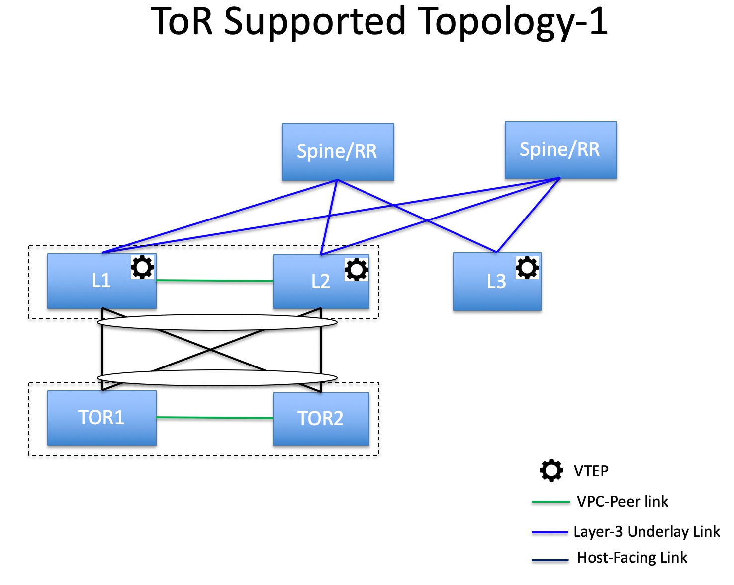
-
ToR switches with port channels connected to both the leaf switches. The L1 and L2 switches are connected as a vPC pair.
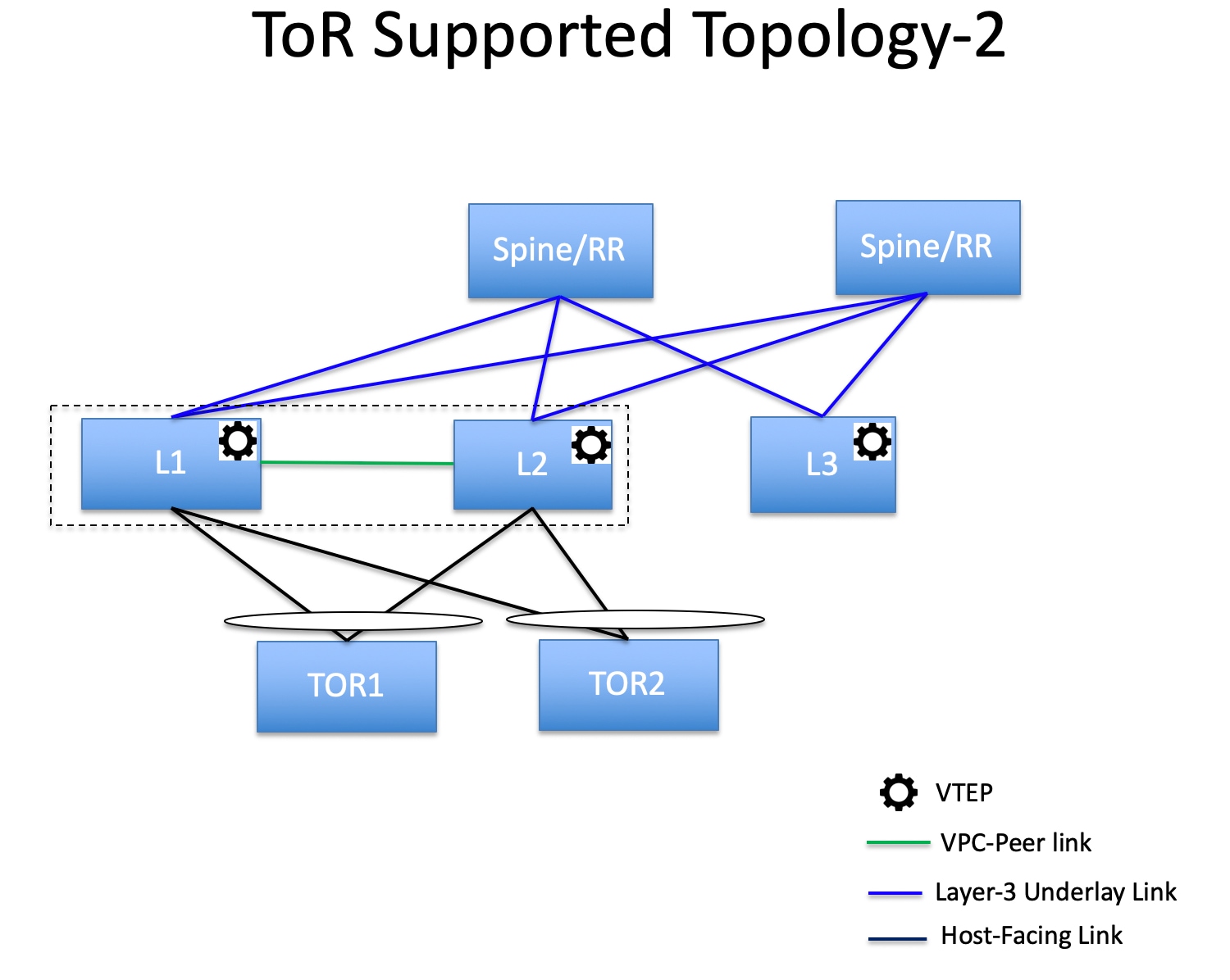
-
ToR switches with port channels directly connected to the leaf switches. The L1 and L2 switches are connected as a vPC pair.
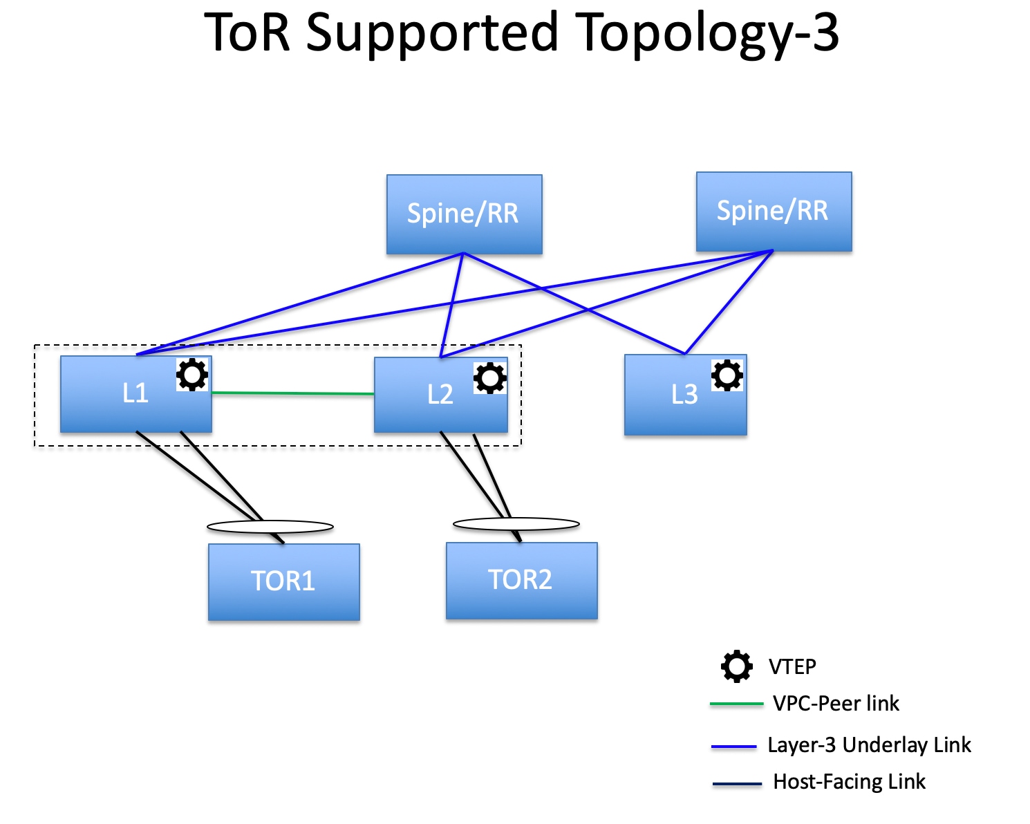
-
ToR switches with port channels directly connected to the leaf switches. vPC pairs are not configured for the leaf or ToR switches.
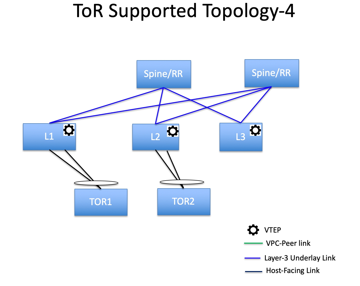
-
ToR switches directly connected to the leaf switches. vPC pairs are not configured for the leaf or ToR switches.
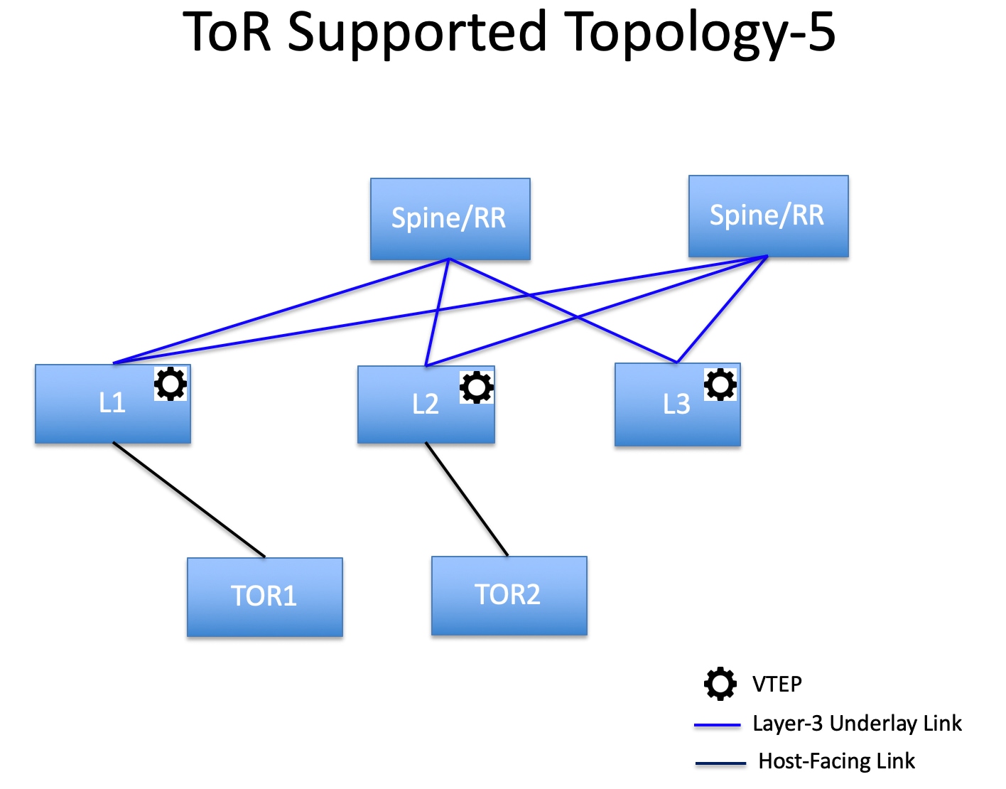
The following topology with ToR switches is not supported in DCNM:
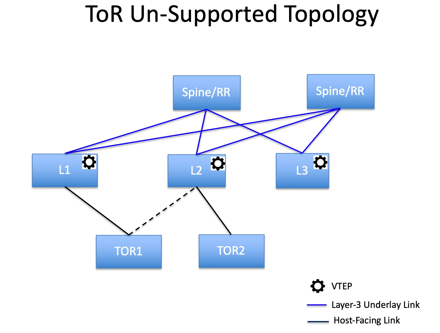
Configuring ToR Switches
Before you begin, make sure you have an Easy Fabric or create and deploy a new fabric. For more information, see Creating a New VXLAN BGP EVPN Fabric.
Note |
DCNM supports the trunk_host policies for the ToR switches. Make sure ToR has vPC policies, port channel, and trunk host. These policies are used to connect the ToR switches in the external fabric to the Leaf switches in the Easy Fabric. |
Procedure
| Step 1 |
Create an external fabric and add two ToR switches. For more information, see Creating an External Fabric. The number of ToR switches can be more than two. This procedure shows how to configure ToR switches as shown in the ToR Topology-1, where ToR switches are connected using vPC. The following are the different scenarios for connecting the ToR switches:
After adding the ToR switches, make sure that the role for the ToR switches is selected as ToR. |
||
| Step 2 |
Right-click a ToR switch and select vPC Pairing. Select the second ToR switch as a vPC Peer. |
||
| Step 3 |
Under vPC Pair Template, enter all the relevant details for a vPC connection between both the ToR switches. For more information about fields and their descriptions, see Creating a vPC Setup in the External Fabric.
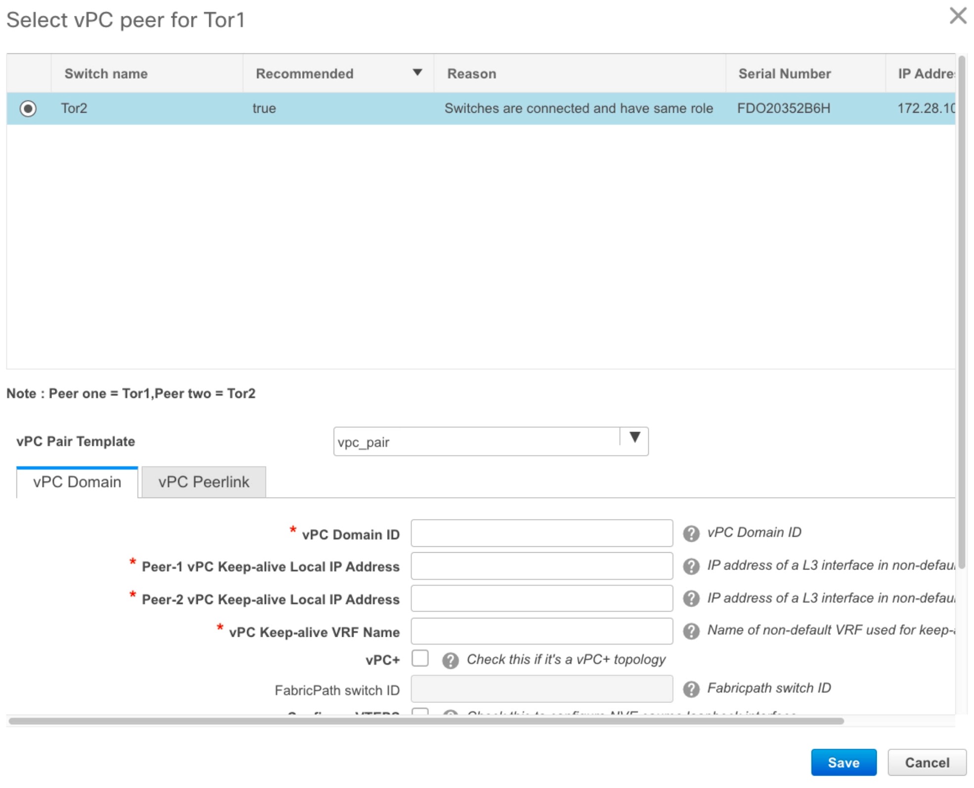 |
||
| Step 4 |
Click Save & Deploy, and then click Deploy Config. |
||
| Step 5 |
After the progress bar shows 100% in the Config Deployment window, click Close. 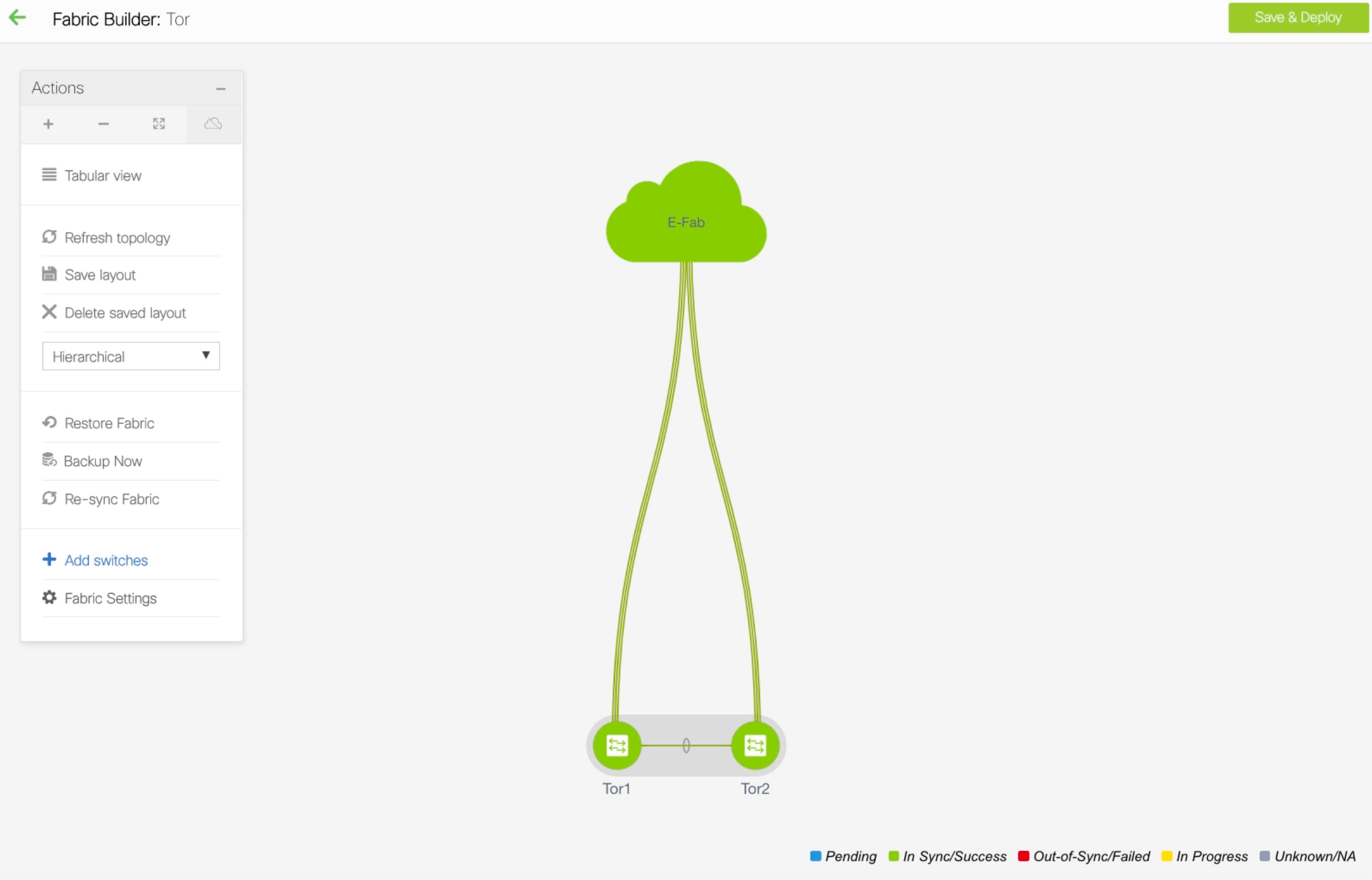 |
||
| Step 6 |
Create an MSD fabric. While creating the MSD fabric, under the General tab, select the ToR Auto-deploy Flag check box. This action enables automatic deployment of the networks and VRFs in the Easy Fabric to the ToR switches in the External Fabric when you click Save & Deploy in the MSD fabric. For more information, see Deploying Networks on ToR Switches. For information about the remaining tabs and fields, see Creating an MSD Fabric. 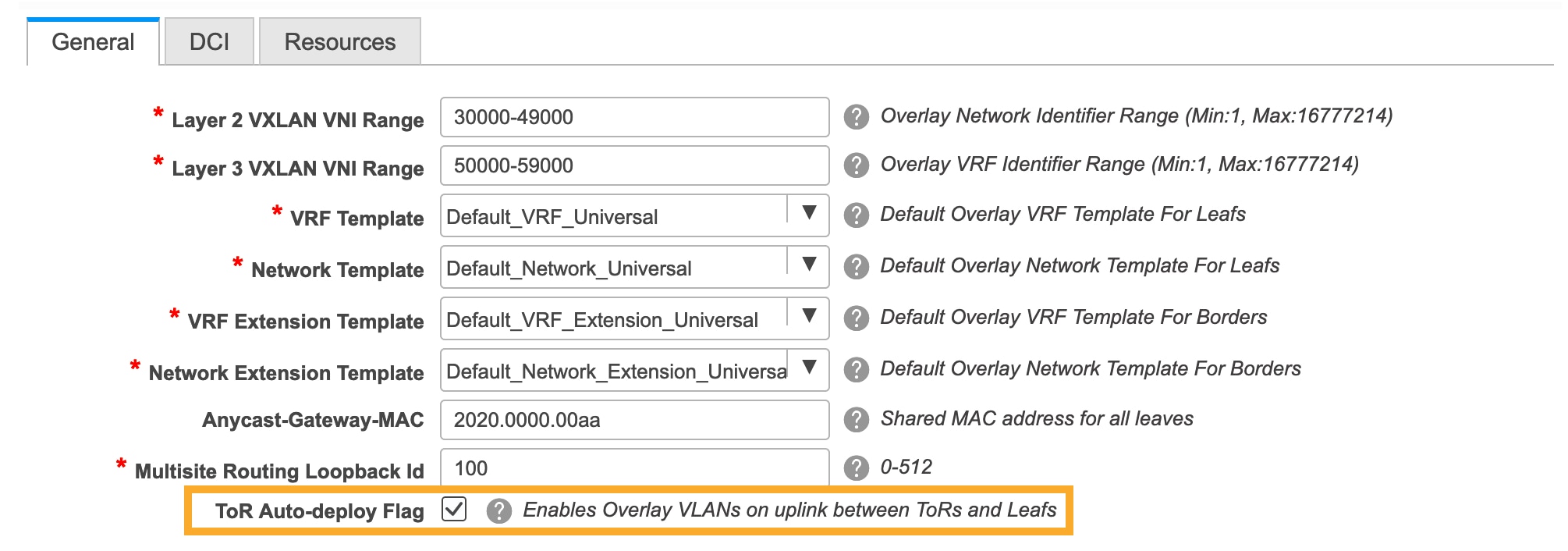 |
||
| Step 7 |
Click Move Fabric in the Action panel. In the Move Fabric window, select the Easy Fabric and click Add. Similarly, move the external fabric that contains the ToR switches to the MSD fabric. 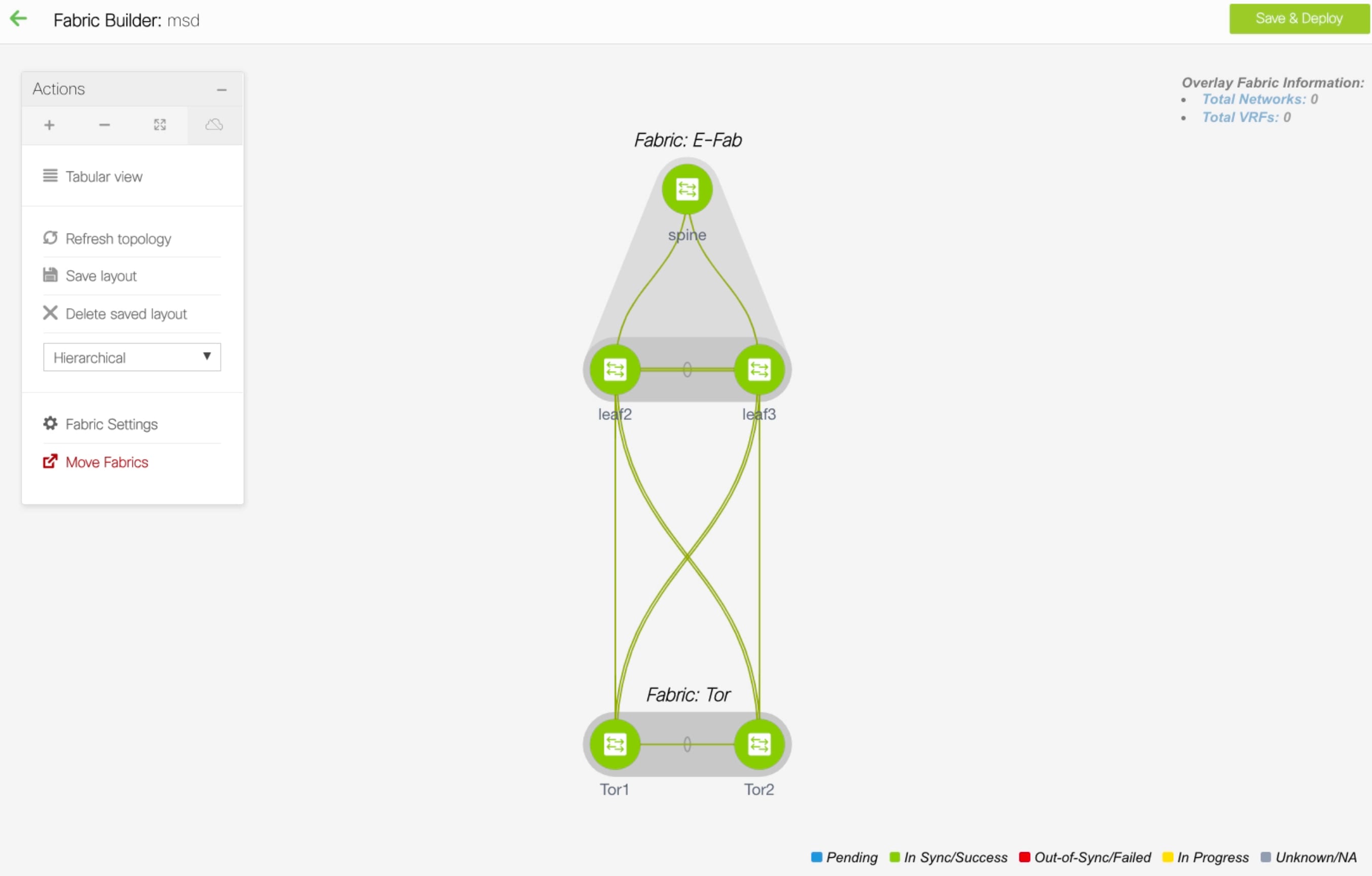 |
||
| Step 8 |
Click the Back icon and click the Easy fabric containing the leaf switches. |
||
| Step 9 |
You need to create a vPC between the leaf and ToR switches. Right-click a leaf switch and select Manage Interfaces. |
||
| Step 10 |
In the Manage Interfaces window, click the Add icon to create a vPC. Enter all the relevant details in the Add Interface window and click Save. 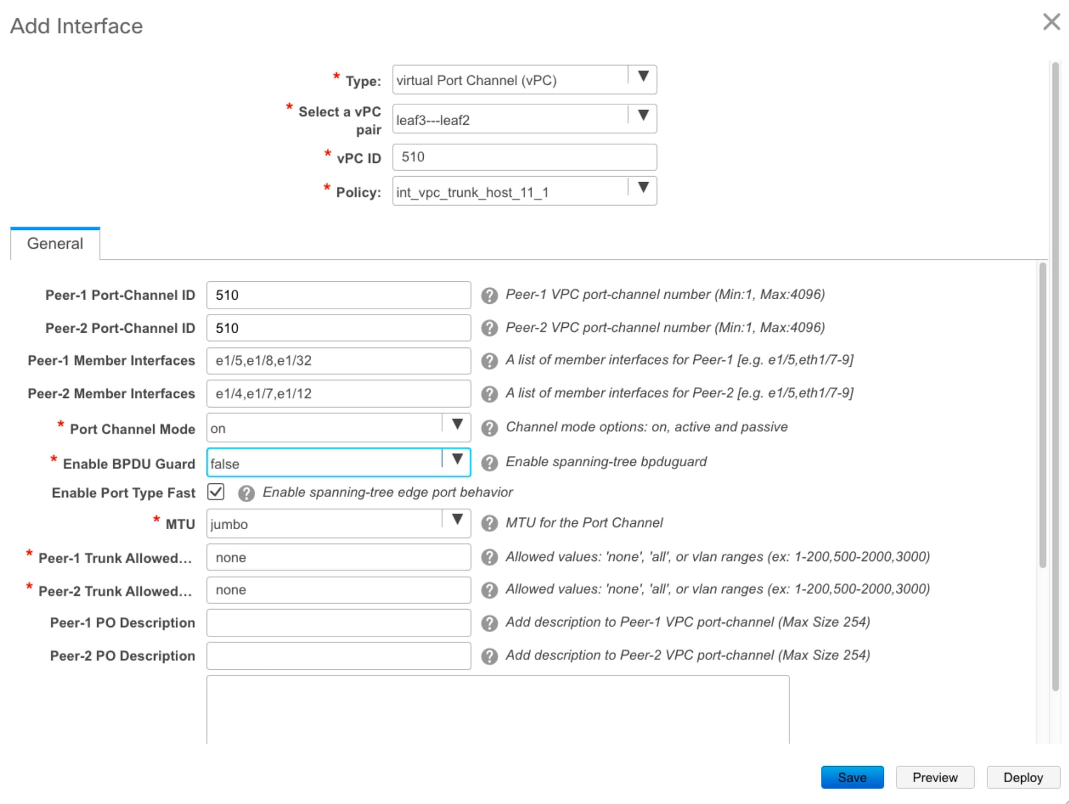 For more information about the fields in this window, see Adding Interfaces. After saving all the information, click Deploy. Similarly, follow the Steps 9 and 10 to create a vPC in the ToR switch as well. 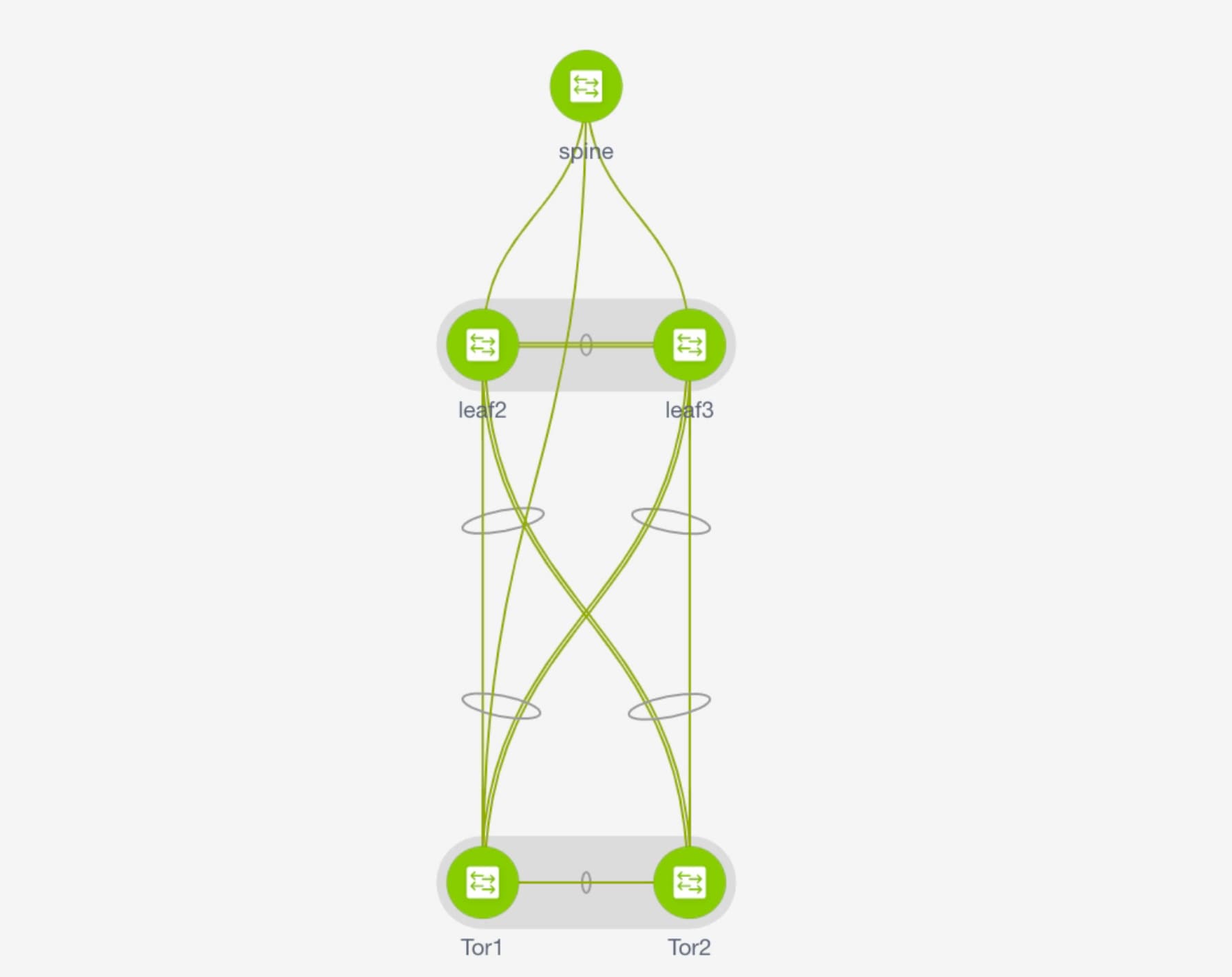 |
Deploying Networks on ToR Switches
Procedure
| Step 1 |
Navigate to Control > Networks. |
||
| Step 2 |
In the Networks window, from the SCOPE drop-down list, select the MSD fabric. |
||
| Step 3 |
Select the networks that you want to deploy or create a new network. For information about creating a network, see Creating Networks for the Standalone Fabric. Click Continue. |
||
| Step 4 |
In the Network Deployment window, select the Multi-select check box and drag the cursor over the leaf switches in the Easy Fabric. 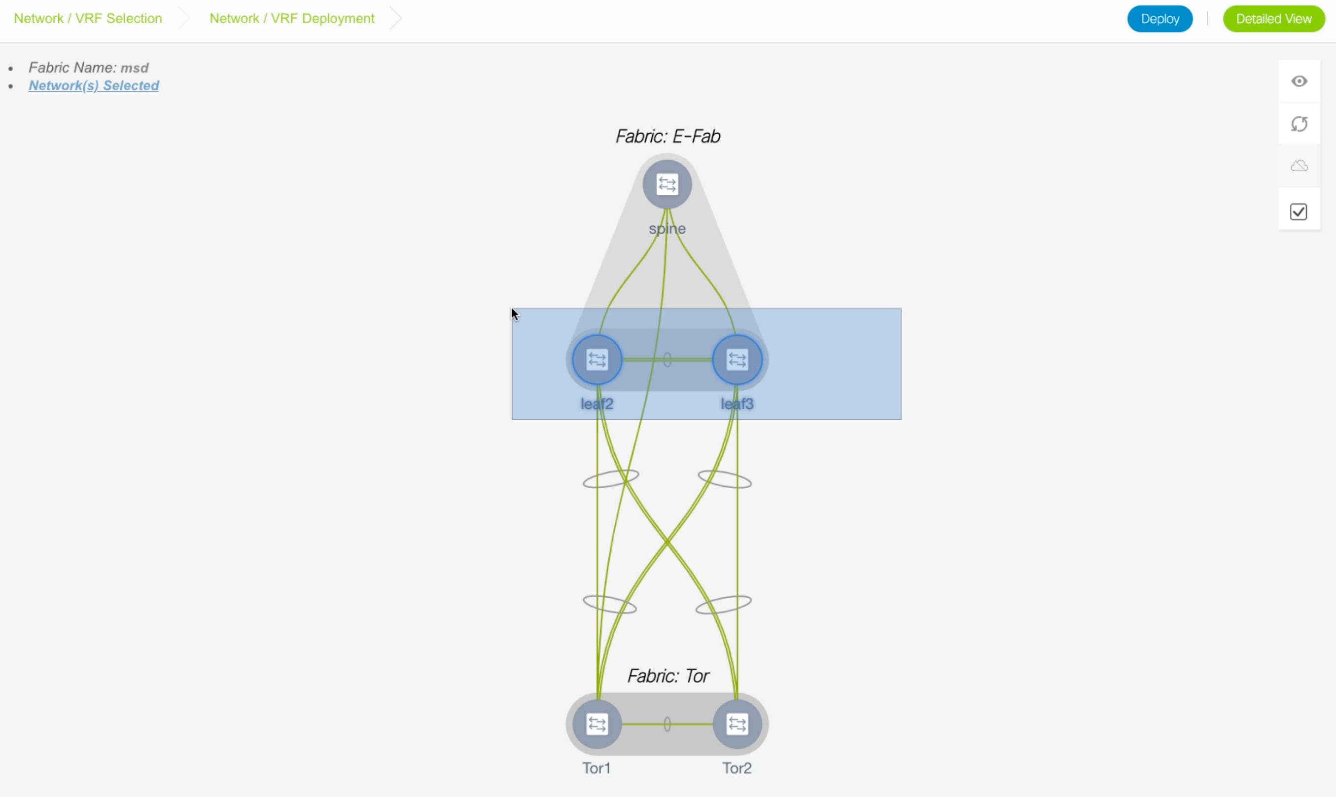 |
||
| Step 5 |
In the Network Attachment window, click ... in the Interfaces column. 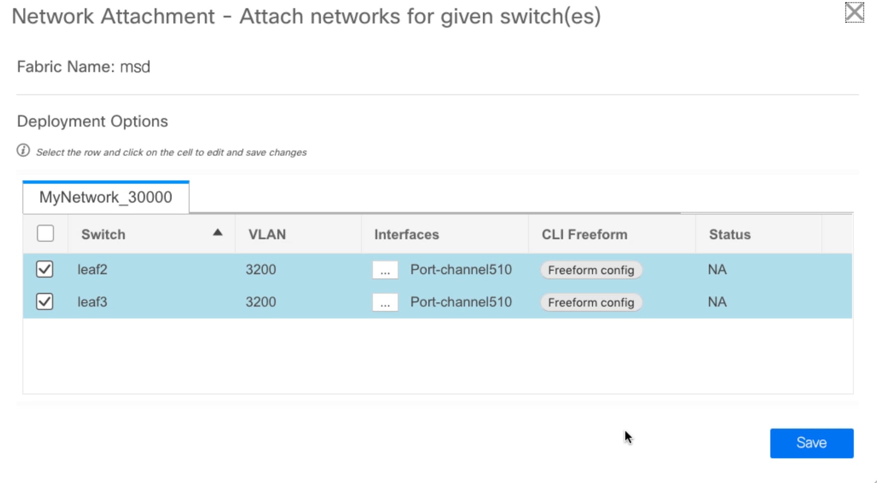 The Interfaces window lists interfaces or port channels. You can select interfaces/port channels to associate them with the selected network. These port channels connect the leaf switches to the ToR switches. The networks will be deployed on these port channels. Click Save and close this window. |
||
| Step 6 |
Click Deploy. Now the VLANs are deployed on the leaf switches. |
||
| Step 7 |
Navigate to Control > Fabric Builder. |
||
| Step 8 |
Click the MSD fabric and click Save & Deploy. The networks created and deployed on the leaf switches in the Easy Fabric are also deployed on the ToR switches in the external fabric. This step allows the same VLANs to be configured on the ToR switches that are deployed on the leaf switches in the Step 6.
|
vPC Fabric Peering
You can create a virtual peer link for two switches or change the existing physical peer link to a virtual peer link. Only greenfield deployments support vPC fabric peering in Cisco DCNM, Release 11.2(1). However, both greenfield as well as brownfield deployments support vPC fabric peering in Cisco DCNM, Release 11.3(1). This feature is applicable for Easy_Fabric_11_1 and Easy_Fabric_eBGP fabric templates.
Note |
The Easy_Fabric_eBGP fabric does not support brownfield import. |
Guidelines and Limitations
The following are the guidelines and limitations for vPC fabric pairing.
-
vPC fabric peering is supported from Cisco DCNM Release 11.2(1) and Cisco NX-OS Release 9.2(3).
-
Only Cisco Nexus N9K-C9332C Switch, Cisco Nexus N9K-C9364C Switch, Cisco Nexus N9K-C9348GC-FXP Switch as also the Cisco Nexus 9000 Series Switches that ends with FX, and FX2 support vPC fabric peering.
-
Cisco Nexus N9K-C93180YC-EX Switch supports vPC fabric peering from Cisco DCNM, Release 11.3(1) and Cisco NX-OS, Release 9.3(1).
-
If you use other Cisco Nexus 9000 Series Switches, a warning will appear during Save & Deploy. A warning appears in this case because these switches will be supported in future releases.
-
If you try pairing switches that do not support vPC fabric peering, using the Use Virtual Peerlink option, a warning will appear when you deploy the fabric.
-
You can convert a physical peer link to a virtual peer link and vice-versa with or without overlays.
-
Switches with border gateway leaf roles do not support vPC fabric peering.
-
vPC fabric peering is not supported for Cisco Nexus 9000 Series Modular Chassis and FEXs. An error appears during Save & Deploy if you try to pair any of these.
-
Brownfield deployments and greenfield deployments support vPC fabric peering in Cisco DCNM, Release 11.3(1).
-
However, you can import switches that are connected using physical peer links and convert the physical peer links to virtual peer links after Save & Deploy. To update a TCAM region during the feature configuration, use the hardware access-list tcam ingress-flow redirect 512 command in the configuration terminal.
Fields and Description
To view the vPC pairing window of a switch, from the fabric topology window, right-click the switch and choose vPC Pairing. The vPC pairing window for a switch has the following fields:
|
Field |
Description |
||
|---|---|---|---|
|
Use Virtual Peerlink |
Allows you to enable or disable the virtual peer linking between switches. |
||
|
Switch name |
Specifies all the peer switches in a fabric.
|
||
|
Recommended |
Specifies if the peer switch can be paired with the selected switch. Valid values are true and false. Recommended peer switches will be set to true. |
||
|
Reason |
Specifies why the vPC pairing between the selected switch and the peer switches is possible or not possible. |
||
|
Serial Number |
Specifies the serial number of the peer switches. |
You can perform the following with the vPC Pairing option:
Creating a Virtual Peer Link
Procedure
| Step 1 |
Choose Control > Fabrics. The Fabric Builder window appears. |
||
| Step 2 |
Choose a fabric with the Easy_Fabric_11_1 or Easy_Fabric_eBGP fabric templates. The fabric topology window appears.  |
||
| Step 3 |
Right-click a switch and choose vPC Pairing from the drop-down list. The window to choose the peer appears. 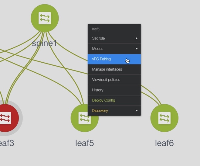
<switch-name> has a Network/VRF attached. Please detach the Network/VRF before vPC Pairing/Unpairing |
||
| Step 4 |
Check the Use Virtual Peerlink check box. |
||
| Step 5 |
Choose a peer switch and check the Recommended column to see if pairing is possible. If the value is true, pairing is possible. You can pair switches even if the recommendation is false. However, you will get a warning or error during Save & Deploy. |
||
| Step 6 |
Click Save.
|
||
| Step 7 |
In the Fabric Topology window, click Save & Deploy. The Config Deployment window appears. |
||
| Step 8 |
Click the field against the switch in the Preview Config column. The Config Preview window appears for the switch. |
||
| Step 9 |
View the vPC link details in the pending configuration and the side-by-side configuration. |
||
| Step 10 |
Close the window. |
||
| Step 11 |
Click the pending errors icon next to the Save & Deploy icon to view errors and warnings, if any. If you see any warnings that are related to TCAM, click the Resolve icon. A confirmation dialog box about reloading switches appears. Click OK. You can also reload the switches from Tabular view in the fabric topology window. The switches that are connected through vPC fabric peering, are enclosed in a gray cloud.
|
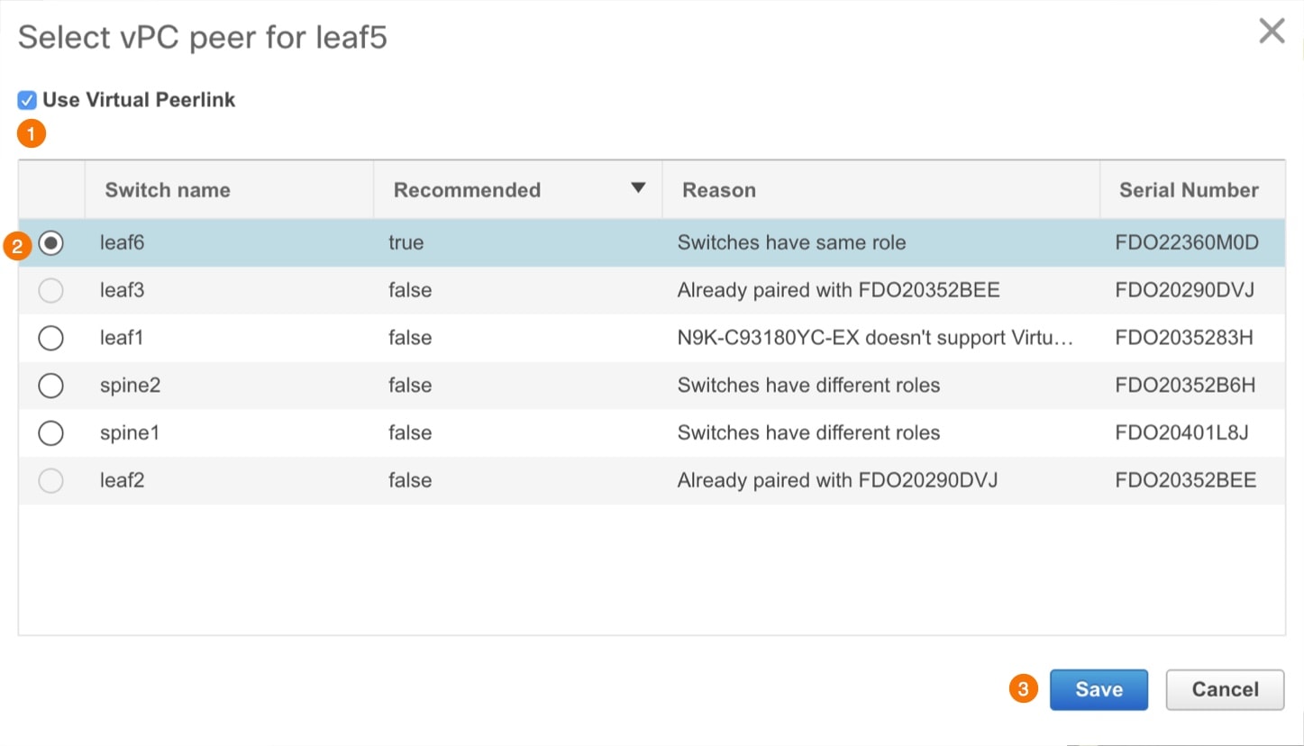
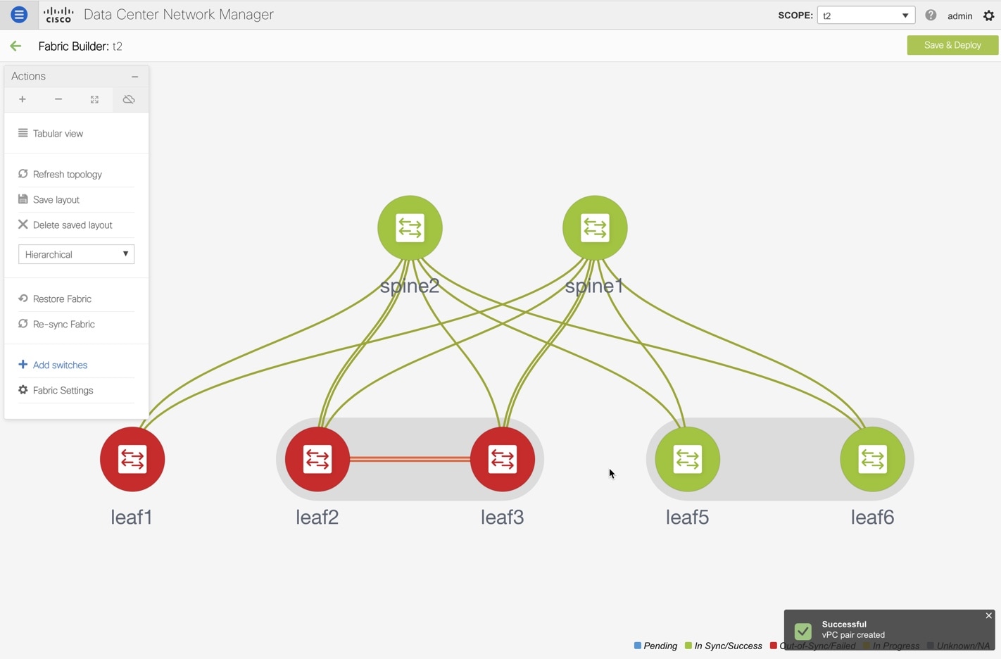
Converting a Physical Peer Link to a Virtual Peer Link
Before you begin
-
Plan the conversion from physical peer link to virtual peer link during the maintenance window of switches.
-
Ensure the switches support vPC fabric peering. Only the following switches support vPC fabric peering:
-
Cisco Nexus N9K-C9332C Switch, Cisco Nexus N9K-C9364C Switch, and Cisco Nexus N9K-C9348GC-FXP Switch
-
Cisco Nexus 9000 Series Switches that ends with FX, FX2, and FX2-Z
-
Procedure
| Step 1 |
Choose Control > Fabrics. The Fabric Builder window appears. |
||
| Step 2 |
Choose a fabric with the Easy_Fabric_11_1 or Easy_Fabric_eBGP fabric templates. |
||
| Step 3 |
Right-click the switch that is connected using the physical peer link and choose vPC Pairing from the drop-down list. The window to choose the peer appears.
<switch-name> has a Network/VRF attached. Please detach the Network/VRF before vPC Pairing/Unpairing |
||
| Step 4 |
Check the Recommended column to see if pairing is possible. If the value is true, pairing is possible. You can pair switches even if the recommendation is false. However, you will get a warning or error during Save & Deploy. |
||
| Step 5 |
Check the Use Virtual Peerlink check box. The Unpair icon changes to Save. |
||
| Step 6 |
Click Save.
|
||
| Step 7 |
In the Fabric Topology window, click Save & Deploy. The Config Deployment window appears. |
||
| Step 8 |
Click the field against the switch in the Preview Config column. The Config Preview window appears for the switch. |
||
| Step 9 |
View the vPC link details in the pending configuration and the side-by-side configuration. |
||
| Step 10 |
Close the window. |
||
| Step 11 |
Click the pending errors icon next to the Save & Deploy icon to view errors and warnings, if any. If you see any warnings that are related to TCAM, click the Resolve icon. A confirmation dialog box about reloading switches appears. Click OK. You can also reload the switches from Tabular view in the fabric topology window. The physical peer link between the peer switches turns red. Delete this link. The switches are connected only through a virtual peer link and are enclosed in a gray cloud. |
Converting a Virtual Peer Link to a Physical Peer Link
Before you begin
Procedure
| Step 1 |
Choose Control > Fabrics. The Fabric Builder window appears. |
| Step 2 |
Choose a fabric with the Easy_Fabric_11_1 or Easy_Fabric_eBGP fabric templates. |
| Step 3 |
Right-click the switch that is connected through a virtual peer link and choose vPC Pairing from the drop-down list. The window to choose the peer appears. |
| Step 4 |
Uncheck the Use Virtual Peerlink check box. The Unpair icon changes to Save. |
| Step 5 |
Click Save. |
| Step 6 |
In the Fabric Topology window, click Save & Deploy. The Config Deployment window appears. |
| Step 7 |
Click the field against the switch in the Preview Config column. The Config Preview window appears for the switch. |
| Step 8 |
View the vPC peer link details in the pending configuration and the side-by-side configuration. |
| Step 9 |
Close the window. |
| Step 10 |
Click the pending errors icon next to the Save & Deploy icon to view errors and warnings, if any. If you see any warnings that are related to TCAM, click the Resolve icon. The confirmation dialog box about reloading switches appears. Click OK. You can also reload the switches from Tabular view in the fabric topology window. The virtual peer link, represented by a gray cloud, disappears and the peer switches are connected through a physical peer link. |
Viewing and Editing Policies
Cisco DCNM provides the ability to group a set of switches, and allows you to push a set of underlay configurations to the group. This release enables you to create a policy template, and apply it to multiple selected switches.
To view, add, deploy, or edit a policy, perform the following steps:
Procedure
| Step 1 |
Choose Control > Fabric Builder. |
||
| Step 2 |
Select any available fabric, and then click Tabular view. |
||
| Step 3 |
Select multiple switches in switches tab, and click View/Edit Policies.
|
Viewing Policies
Procedure
| Step 1 |
Choose Control > Fabric Builder. |
||
| Step 2 |
Select any available fabric, and then click Tabular view. |
||
| Step 3 |
Select multiple switches in the switches tab and click View/Edit Policies. Policies are listed in view or edit policies table for multiple switches.
|
||
| Step 4 |
Select a policy and click the View button to view its configs.
|
||
| Step 5 |
In the View/Edit Policies window, click View All to view all the configurations pushed to the switches using policies. 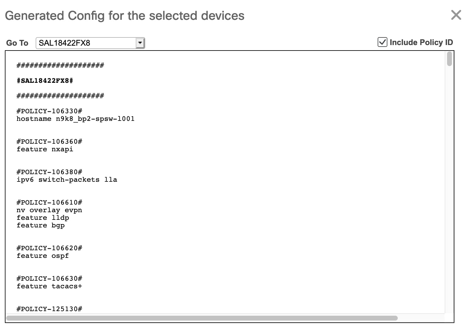 Go To: Select a device from this drop-down list to navigate to its starting config. This option is applicable only when you view policies for multiple devices. Include Policy ID: Select this check box to view policy IDs for all the policies. By default, this check box is selected. |
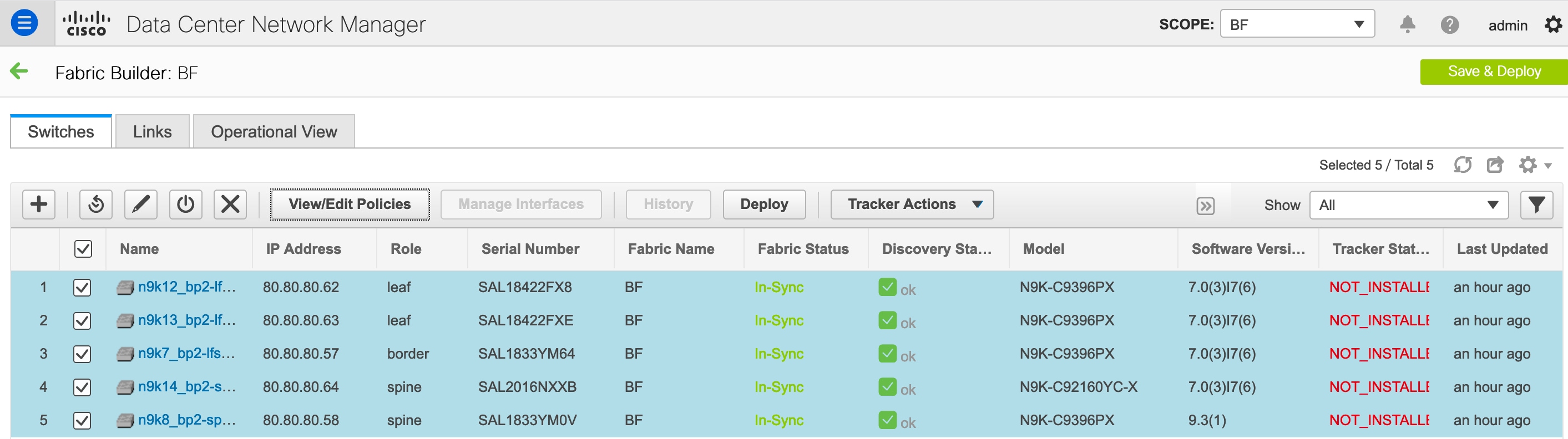
Adding a Policy
Procedure
| Step 1 |
Choose Control > Fabric Builder. |
| Step 2 |
Select any available fabric, and then click Tabular view. |
| Step 3 |
Select a single or multiple switches in the Switches tab, and click the View/Edit Policies button. |
| Step 4 |
Click the Add icon. |
| Step 5 |
Select a policy template and enter the mandatory parameters data and click Save. PTI is added per each device based on n-number of devices selection.
Policy: Select a policy from this drop-down list. Priority: Specify a priority for the policy. The applicable values are from 1 to 1000. The default value is 500. The lower number in the Priority field means that there is a higher priority for the generated configuration and POAP startup-configuration. For example, features are 50, route-maps are 100, and vpc-domain is 200. Description: (Optional) Specify a description for the policy. This field is used to differentiate multiple freeform policies. The Description column is added in the View/Edit Policies window, which you can use to filter or find policies based on description. |
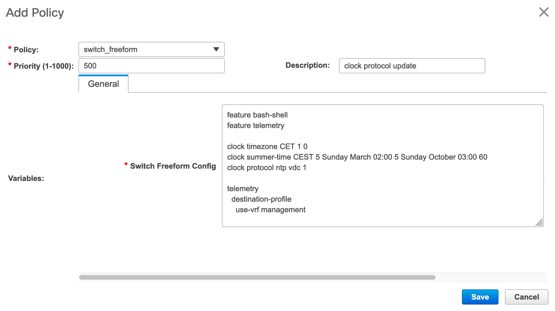
Deploying Policies
Procedure
| Step 1 |
Choose Control > Fabric Builder. |
| Step 2 |
Select any available fabric, and then click Tabular view. |
| Step 3 |
Select multiple switches in the switches tab, and click the View/Edit Policies button. |
| Step 4 |
Select multiple polices, and then click Push Config. The selected PTI’s configs are pushed to the group of switches. |
Editing a Policy
Note |
Multiple policy editing is not supported. |
Procedure
| Step 1 |
Choose Control > Fabric Builder. |
||
| Step 2 |
Select any available fabric, and then click Tabular view. |
||
| Step 3 |
Select multiple switches in the switches tab, and click the View/Edit Policies button. 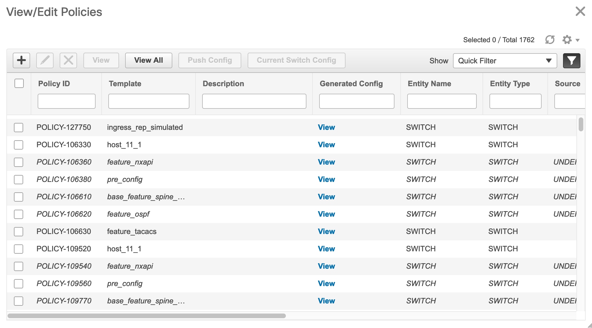
|
||
| Step 4 |
Select a PTI, click Edit to modify the required data, and then click Save to save the PTI. |
||
| Step 5 |
Select a PTI, click Edit to modify the required data, and then click Push Config to push the policy config to the device.
|
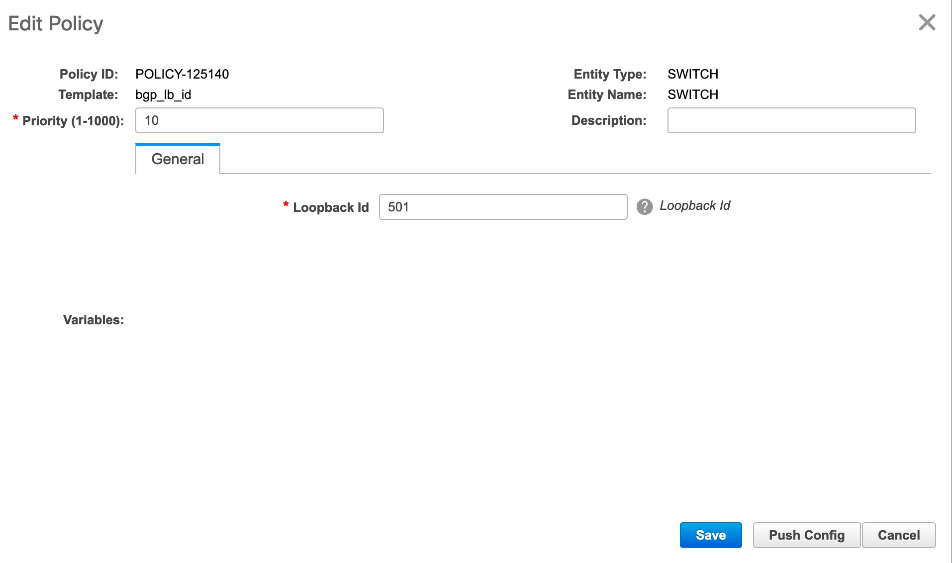
Current Switch Configuration
Procedure
| Step 1 |
Choose Control > Fabric Builder. |
||
| Step 2 |
Select any available fabric, and then click Tabular view. |
||
| Step 3 |
Select multiple switches in the switches tab, and click View/Edit Policies. |
||
| Step 4 |
Click Current Switch Config. The current switch configuration appears in the Running Config dialog box.
|
Changing Fabric Interface Numbering
Procedure
| Step 1 |
Select an existing fabric from the Fabric Builder window. |
| Step 2 |
Click Tabular view in the Actions menu. |
| Step 3 |
Click the Links tab. |
| Step 4 |
Select the link connecting a Spine and a Leaf, and click the Update Link icon. |
| Step 5 |
In the Link Template field, select int_intra_fabric_unnum_link_11_1. |
| Step 6 |
Click Save and close the Link Management - Edit Link window. |
| Step 7 |
Repeat this procedure for the all the links connecting a Spine and a Leaf. |
| Step 8 |
Navigate back to the fabric, and click the Fabric Settings in the Actions menu. |
| Step 9 |
Under the General tab, select unnumbered from the Fabric Interface Numbering drop-down list. |
| Step 10 |
Click Save and close the window. |
| Step 11 |
Click Save & Deploy to deploy the updated configuration. |
Retrieving the Authentication Key
Retrieving the 3DES Encrypted OSPF Authentication Key
-
SSH into the switch.
-
On an unused switch interface, enable the following:
config terminal
    feature ospf
    interface Ethernet1/1
       no switchport
       ip ospf message-digest-key 127 md5 ospfAuth
In the example, ospfAuth is the unencrypted password.
Note
This Step 2 is needed when you want to configure a new key.
-
Enter the show run interface Ethernet1/1 command to retrieve the password.
Switch # show run interface Ethernet1/1
   interface Ethernet1/1
     no switchport
     ip ospf message-digest key 127 md5 3 sd8478f4fsw4f4w34sd8478fsdfw
     no shutdown
The sequence of characters after md5 3 is the encrypted password.
-
Update the encrypted password into the OSPF Authentication Key field.
Retrieving the Encrypted IS-IS Authentication Key
To get the key, you must have access to the switch.
-
SSH into the switch.
-
Create a temporary keychain.
config terminal
   key chain isis
   key 127
   key-string isisAuth
In the example, isisAuth is the plaintext password. This will get converted to a Cisco type 7 password after the CLI is accepted.
-
Enter the show run | section “key chain” command to retrieve the password.
key chain isis
   key 127
       key-string 7 071b245f5a
The sequence of characters after key-string 7 is the encrypted password. Save it.
-
Update the encrypted password into the ISIS Authentication Key field.
-
Remove any unwanted configuration made in Step 2.
Retrieving the 3DES Encrypted BGP Authentication Key
-
SSH into the switch and enable BGP configuration for a non-existent neighbor.
Note
Non-existent neighbor configuration is a temporary BGP neighbor configuration for retrieving the password.
router bgp
   neighbor 10.2.0.2 remote-as 65000
   password bgpAuth
In the example, bgpAuth is the unencrypted password.
-
Enter the show run bgp command to retrieve the password. A sample output:
neighbor 10.2.0.2
   remote-as 65000
   password 3 sd8478fswerdfw3434fsw4f4w34sdsd8478fswerdfw3434fsw4f4w3
The sequence of characters after password 3 is the encrypted password.
-
Update the encrypted password into the BGP Authentication Key field.
-
Remove the BGP neighbor configuration.
Retrieving the Encrypted BFD Authentication Key
-
SSH into the switch.
-
On an unused switch interface, enable the following:
switch# config terminal
switch(config)# int e1/1
switch(config-if)# bfd authentication keyed-SHA1 key-id 100 key cisco123
In the example, cisco123 is the unencrypted password and the key ID is 100.
Note
This Step 2 is needed when you want to configure a new key.
-
Enter the show running-config interface command to retrieve the key.
switch# show running-config interface Ethernet1/1

interface Ethernet1/1
description connected-to- switch-Ethernet1/1
no switchport
mtu 9216
bfd authentication Keyed-SHA1 key-id 100 hex-key 636973636F313233
no ip redirects
ip address 10.4.0.6/30
no ipv6 redirects
ip ospf network point-to-point
ip router ospf 100 area 0.0.0.0
no shutdown
The BFD key ID is 100 and the encrypted key is 636973636F313233.
-
Update the key ID and key in the BFD Authentication Key ID and BFD Authentication Key fields.
Return Material Authorization (RMA)
This section describes how to replace a physical switch in a Fabric when using Cisco DCNM Easy Fabric mode.
Prerequisites
-
Fabric is assumed to be up and running, and minimal disruption is desired when replacing the switch. Also, the switch must be replaced with a switch of the same model (ASIC type) and physical port configuration.
-
To use the POAP RMA flow, you must configure the fabric for bootstrap (POAP).
-
To copy the FEX configurations for the RMA of switches which have FEX deployed, you may need to perform the Save and Deploy operation one or two times.
Guidelines and Limitations
-
The switch must be replaced with a switch of the same model (ASIC type) and physical port configuration. If not, the old switch must be removed and a new switch (replacement) added as a new switch into the fabric.
POAP RMA Flow
Procedure
| Step 1 |
Choose Control > Fabric Builder. |
| Step 2 |
Click the Fabric where you want to perform RMA. |
| Step 3 |
Move the device into maintenance mode. To move a device into maintenance mode, right-click on the device, and then choose Modes > Maintenance Mode. 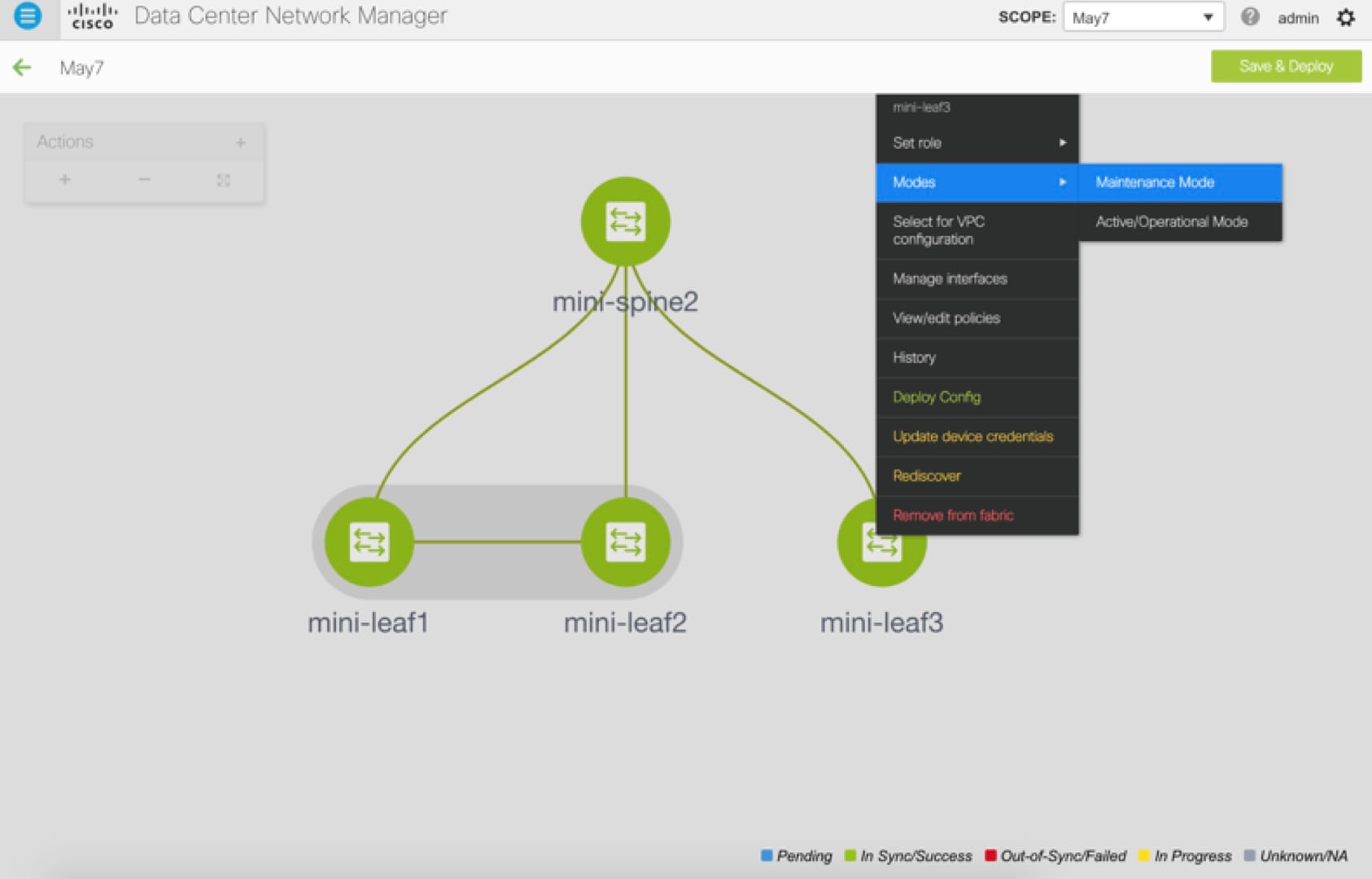 |
| Step 4 |
Physically replace the device in the network. Physical connections should be made in the same place on the replacement switch as they existed on the original switch. |
| Step 5 |
Provision RMA flow and select the replacement device. 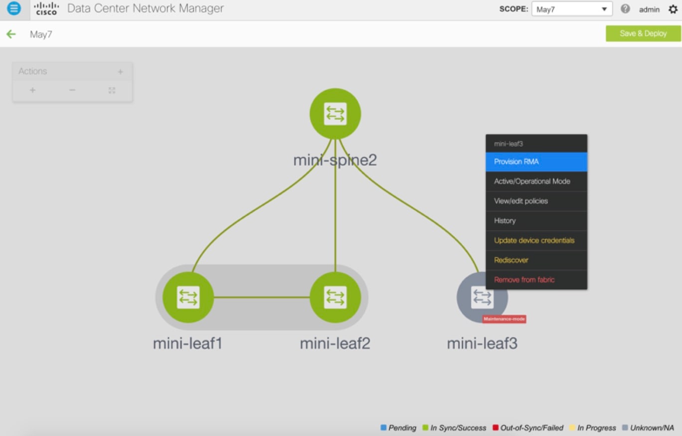 |
| Step 6 |
The Provision RMA UI will show the replacement device 5-10 minutes after it is powered on. 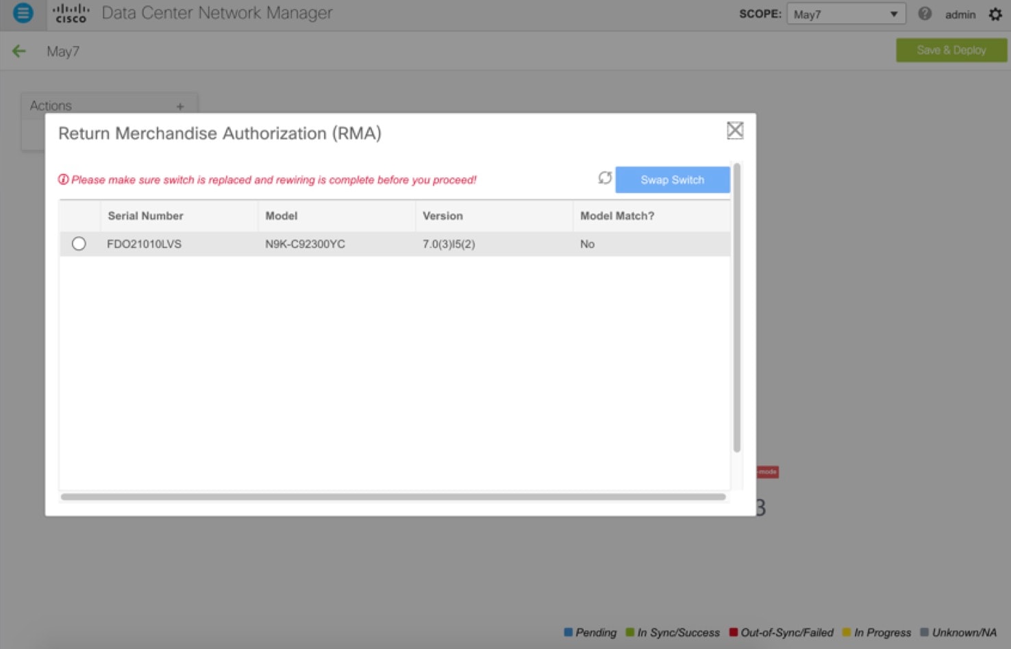 |
| Step 7 |
Select the correct replacement device and click Swap Switch. This begins POAP with the full “expected” configuration for that device. Total POAP time is generally around 10-15 minutes. 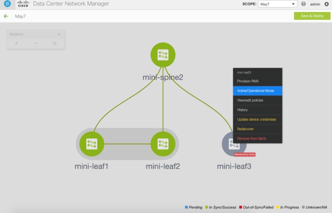 |
Manual RMA Flow
Use this flow when “Bootstrap” is not possible (or not desired), including cases that are IPv6 only for the initial Cisco DCNM 11.0(1) release.
Procedure
| Step 1 |
Place the device in maintenance mode (optional). 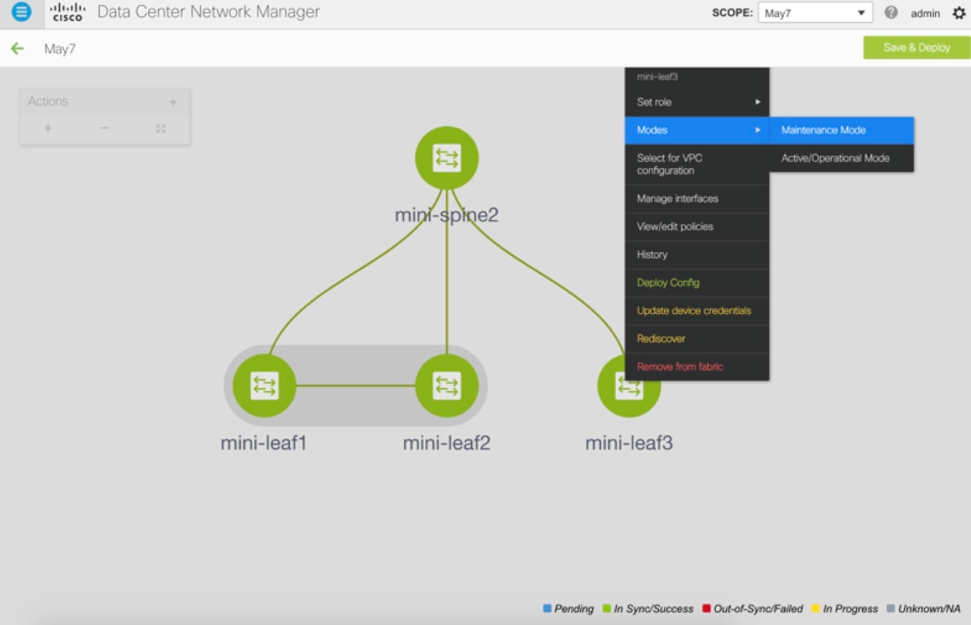 |
| Step 2 |
Physically replace the device in the network. |
| Step 3 |
Log in through Console and set the Management IP and credentials. |
| Step 4 |
The Cisco DCNM rediscovers the new device (or you can manually choose Discovery > Rediscover). |
| Step 5 |
Deploy the expected configuration using Deploy. 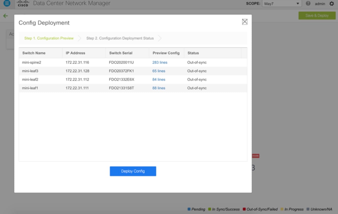 |
| Step 6 |
Depending on the configuration, if breakout ports or FEX ports are in use, you have to deploy again to completely restore the configuration. |
| Step 7 |
After a successful deployment, and the device is “In-Sync,” you must move the device back to Normal Mode. 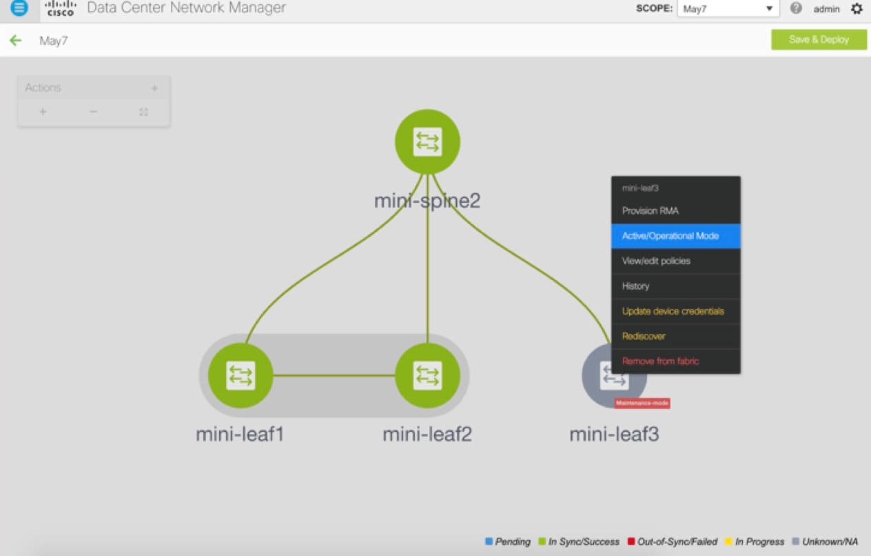 |
RMA for User with Local Authentication
Note |
This task is only applicable to non-POAP switches. |
Use the following steps to perform RMA for a user with local authentication:
Procedure
| Step 1 |
After the new switch comes online, SSH into the switch and reset the local user passwords with the cleartext password using the “username” command. Reset the local user passwords to resync the SNMP password. The password is stored in the configuration file in a nontransferable form. |
| Step 2 |
Wait for the RMA to complete. |
| Step 3 |
Update Cisco DCNM switch_snmp_user policy for the switch with the new SNMP MD5 key from the switch. |
Interfaces
The Interfaces option displays all the interfaces that are discovered for the switch, Virtual Port Channels (vPCs), and intended interfaces missing on the device.
You can use the following functions:
-
Create, deploy, view, edit and delete a port channel, vPC, Straight-through FEX, Active-Active FEX, loopback, and subinterface.
Note
The following features are unsupported for the brownfield migration of switches with the Cisco NX-OS Release 7.0(3)I4(8b) and 7.0(4)I4(x) images:
-
FEX on switches other than Cisco Nexus 9300 Series switches and Cisco Nexus 9500 Series switches with X9500 line cards
-
AA-FEX
For information about the platform support for FEX, refer to your platform and NX-OS documentation to check the feature compatibility.
-
-
Create tunnel interfaces for Cisco Cloud Services Router 1000v Series (Cisco CSR 1000v Series).
-
Create breakout and unbreakout ports.
-
Shut down and bring up interfaces.
-
Rediscover ports and view interface configuration history.
-
Apply host policies on interfaces and vPCs. For example, int_trunk_host_11_1, int_access_host_11_1, and so on.
-
View interface information such as its admin status, operation status, reason, policy, speed, MTU, mode, VLANs, IP/Prefix, VRF, port channel, and the neighbor of the interface.
Note
The Neighbor column provides details of connected switches that are discovered, intent links, and Virtual Machine Manager (VMM) connectivity. You can navigate to the Switch dashboard of the corresponding switch by clicking it. However, intent links and VMM links are not hyperlinked and you cannot navigate to the corresponding Switch dashboard.
The Status column displays the following statuses of an interface:
-
Blue: Pending
-
Green: In Sync/Success
-
Red: Out-of-Sync/Failed
-
Yellow: In Progress
-
Grey: Unknown/NA
-
However, you cannot add or edit interfaces for ASR 9000 Series Routers and Arista switches.
You can filter and view information for any of the given fields (such as Device Name). The following table describes the buttons that appear on this page.
Note |
|
|
Field |
Description |
|---|---|
|
Add |
Allows you to add a logical interface such as a port channel, vPC, Straight-through FEX, Active-Active FEX, loopback and subinterface. |
|
Breakout, Unbreakout |
Allows you to breakout an interface or unbreakout interfaces that are in breakout state. |
|
Edit |
Allows you to edit and change policies that are associated with an interface. |
|
Delete |
Allows you to delete a logical interface that is created from the Interfaces screen. An interface having a policy that is attached from an overlay and underlay cannot be deleted. |
|
No Shutdown |
Allows you to enable an interface (no shutdown or admin up). |
|
Shutdown |
Allows you to shut down the interface. |
|
Show |
Allows you to display the interface show commands. A show command requires show templates in the template library. |
|
Rediscover |
Allows you to rediscover or recalculate the compliance status on the selected interfaces. |
|
Interface History |
Allows you to display the interface deployment history details. |
|
Deploy |
Allows you to deploy or redeploy saved interface configurations. |
This section contains the following:
Adding Interfaces
Procedure
| Step 1 |
Choose Control > Interfaces. You see the Scope option at the top right part of the screen. If you want to view interfaces for a specific fabric, select the fabric window from the list. |
||
| Step 2 |
Click Add to add a logical interface. The Add Interface window appears. |
||
| Step 3 |
In the Type drop-down list, choose the type of the interface.
|
||
| Step 4 |
In the Select a Device field, choose the device. Devices are listed based on the fabric and interface type. External fabric devices are not listed for ST FEX and AA FEX. In the case of vPC or Active to Active FEX, select the vPC switch pair. |
||
| Step 5 |
Enter the ID value in the respective interface ID field (Port-channel ID, vPC ID, Loopback ID and Subinterface ID) that is displayed, based on the selected interface. You can override this value. The new value is used only if it is available in the Resource Manager pool. Else, it results in an error. |
||
| Step 6 |
In the Policy field, you can select the policy to be applied on an interface. The field only lists the Interface Python Policy with tag interface_edit_policy and filtered based on the interface type. You must not create a _upg interface policy. For example, you should not create a policy using the vpc_trunk_host_upg, port_channel_aa_fex_upg, port_channel_trunk_host_upg, and trunk_host_upg options. |
||
| Step 7 |
Click Save to save the configurations.
Only saved configurations are pushed to the device. While adding the interface, you can only modify the policy attribute after the first save. If you try to use an ID that is already used, you will encounter the Resource could not be allocated error. |
||
| Step 8 |
(Optional) Click the Preview option to preview the configurations to be deployed. |
||
| Step 9 |
Click Deploy to deploy the specified logical interface. The newly added interface appears in the screen. Breakout or Unbreakout: You can break out and unbreakout an interface by using the breakout option at the top left part of the screen. |
Editing Interfaces
To edit the interfaces from the Cisco DCNM Web UI, perform the following steps:
Note |
The Edit Interface allows you to change the policy and add or remove an interface from a port channel or vPC. |
Procedure
| Step 1 |
Choose Control > Interfaces. You can break out and unbreak out an interface by using the breakout option at the top left part of the screen. |
| Step 2 |
Select the interface check box to edit an interface or vPC. Select corresponding check boxes for editing multiple interfaces. You cannot edit multiple port channels and vPC. You cannot edit interfaces of different types at the same time. |
| Step 3 |
Click Edit to edit an interface. The variables that are shown in the Edit Configuration window are based on the template and its policy. Select the appropriate policy. Preview the policy, save it and deploy the same. This window lists only Interface Python Policy with the tag interface_edit_policy and filtered based on the interface type. In a vPC setup, the two switches are in the order the switch names are displayed in the edit window. For example, if Switch Name is displayed as LEAF1:LEAF2, then Leaf1 is peer switch one and Leaf2 is peer switch two. During overlay network deployment on switches, the network can be associated with trunk interfaces. The trunk interface to network association is reflected in the Interfaces screen. You can update such interfaces. For interface policies that are not created from the Control > Interfaces screen, you can edit some configurations but not change the policy itself. The policy and fields that cannot be edited are grayed out. The following are some examples of policies that cannot be edited:
|
Editing Interfaces Associated with Links
There are two types of links, namely intra-fabric links and inter-fabric links. As the name implies, intra-fabric links are set up between devices within the same Easy fabric and are typically used for spine-leaf connectivity. Inter-fabric links are set up between the Easy fabric, and typically other external or Easy fabrics. They are used for external WAN and/or DCI connectivity. A policy is associated with each link that effectively states the configuration that is applied to both ends of the link. In other words, the link policy becomes the parent of the individual child interface policies that are associated with the two interfaces that form the link. In this scenario, you must edit the link policy to edit the interface policy fields such as description, IP address, and any per interface freeform config. The following procedure shows how to edit the interfaces associated with links:
Procedure
| Step 1 |
Choose Control > Fabric Builder, and select the fabric containing the link. |
| Step 2 |
Click Tabular view in the Actions panel. A window with the Switches and Links tabs appears. |
| Step 3 |
Click the Links tab. |
| Step 4 |
Select the link that you want to edit and click the Update Link icon. 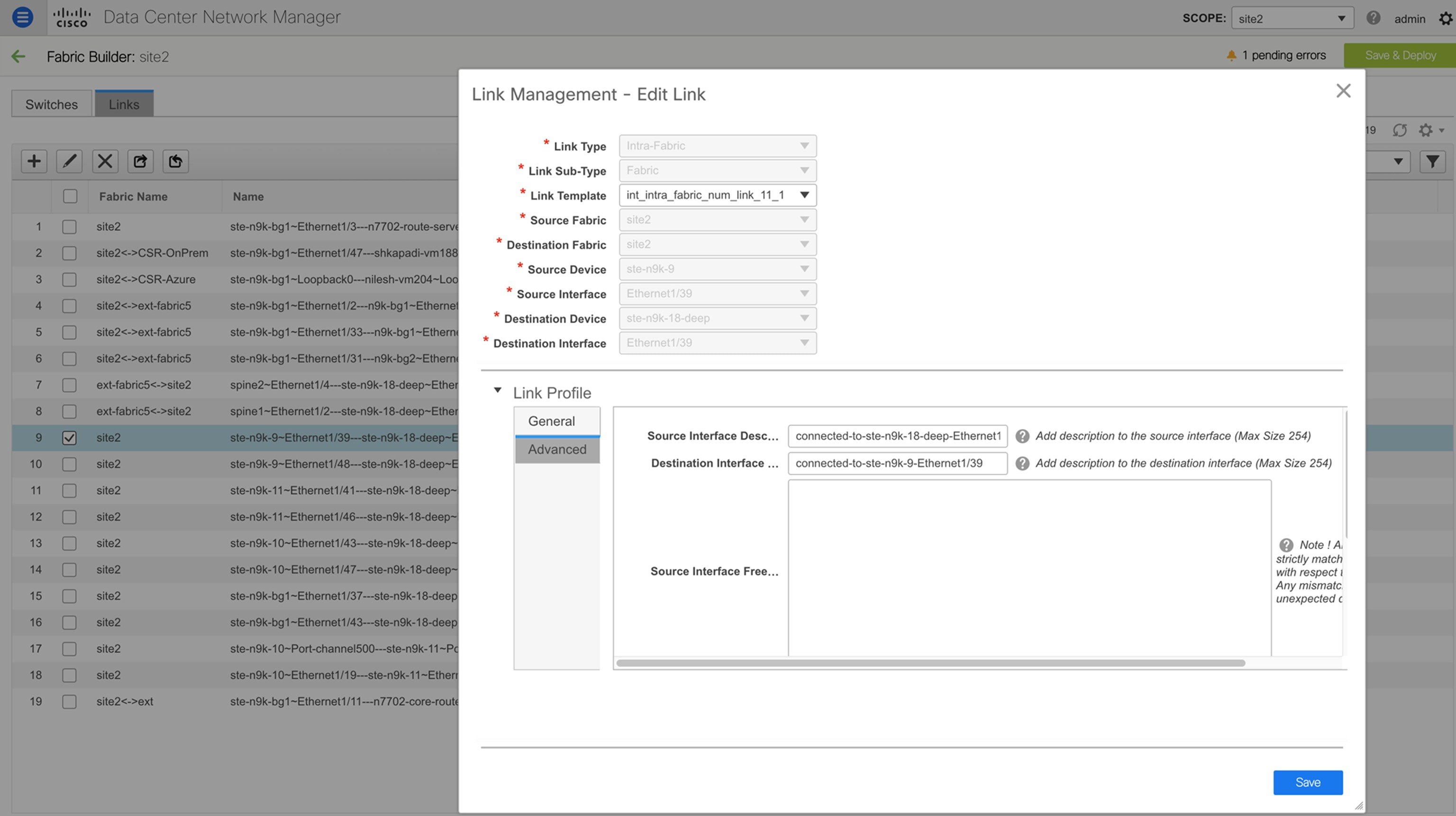 Update the link based on your requirements and click Save. |
Deleting Interfaces
To delete the interfaces from the Cisco DCNM Web UI, perform the following steps:
Note |
This option allows you to delete only logical ports, port channels, and vPCs. You can delete the interface if it does not have overlay or underlay policy attached. When a port channel or vPC is removed, the corresponding member ports get the default policy associated. The Default Policy can be configured in server.properties file. |
Procedure
| Step 1 |
Choose Control > Interfaces. |
| Step 2 |
Select the interfaces. |
| Step 3 |
Click Delete to delete the interface. You cannot delete logical interfaces created in the fabric underlay. |
Shutting Down and Bringing Up Interfaces
Procedure
| Step 1 |
Choose Control > Interfaces. |
| Step 2 |
Select the interfaces that you want to shut down or bring up. |
| Step 3 |
Click Shutdown to disable the selected interfaces. For example, you may want to isolate a host from the network or a host that is not active in the network. |
| Step 4 |
Click No Shutdown to bring up the selected interfaces. |
Viewing Interface Configuration
Procedure
| Step 1 |
Choose Control > Interfaces. Select the interface whose configurations you want to view. |
| Step 2 |
In the Interface Show Commands window, select the action from the Show drop-down box and click Execute. The interface configurations are displayed in the Output section, at the right of the screen. For Show commands, you must have corresponding show templates for interface or interface sub types like port channel or vPC, defined in the Template Library. |
Rediscovering Interfaces
Procedure
| Step 1 |
Choose Control > Interfaces. |
| Step 2 |
Select the interfaces that you want to rediscover. |
| Step 3 |
Click Rediscover to rediscover the selected interfaces. For example, after you edit or enable an interface, you can rediscover the interface. |
Viewing Interface History
Procedure
| Step 1 |
Choose Control > Interfaces. |
| Step 2 |
Select the interface. |
| Step 3 |
Click Interface History to view the configuration history on the interface. |
| Step 4 |
Click Status to view each command that is configured for that configuration instance. |
Deploying Interface Configurations
Procedure
| Step 1 |
Choose Control > Interfaces. |
||
| Step 2 |
Choose an interface you want to deploy.
|
||
| Step 3 |
Click Deploy to deploy or redeploy configurations that are saved for an interface. After you deploy the interface configuration, the interface status information is updated. However, the overall switch-level state may be in the pending state, which is in blue. The overall switch-level state goes to the pending state whenever there is a change in intent from any module, such as interface, link, policy template update, top-down, or so on. In the pending state, a switch may have pending configurations or switch-level recomputation. The switch-level recomputation occurs when:
Preview or deploy the switches to review their state and to understand the root cause of their pending state. Save and deploy for a fabric-wide recomputation. |
Creating External Fabric Interfaces
You can add and edit port channel, vPC, subinterface, and loopback interfaces for external fabric devices. You cannot add Straight-through FEX and Active-Active FEX functions.
The Breakout port function is only supported for Cisco Nexus 9000 and 3000 series switches in the external fabric.
When you add an interface to an external fabric device, the Resource Manager is not in sync with the device. So, ensure that the value populated in the ID field (Port-channel ID, vPC ID, Loopback ID, etc) is not previously configured on the switch.
If you want to configure a portchannel in the external fabric, you should add and deploy the feature_lacp policy on the switches where the portchannel will be configured.
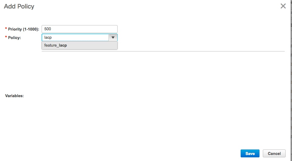
When an external fabric is set to Fabric Monitor Mode Only, you cannot deploy configurations on its switches. If you click Save & Deploy in the fabric topology screen, it displays an error message. However, the following settings (available when you right-click the switch icon) are allowed:
vPC pairing - You can designate a vPC switch pair, but it is only for reference.
View/edit policy - You can add a policy but you cannot deploy it on the switch.
Manage interfaces – You can only create intent for adding interfaces. If you try to deploy, edit, or delete interfaces, it results in an error message.
Creating and Deploying Networks and VRFs
The steps for overlay networks and VRFs provisioning are:
-
Create networks and VRFs for the fabric.
-
Deploy the networks and VRFs on the fabric switches.
Note |
The undeployment and deletion of overlay networks and VRFs are explained after the explanation of deployment. Finally, creation of external fabrics and fabric extensions from VXLAN to external fabrics are documented. |
The two steps are explained:
Viewing Networks and VRFs for a Fabric
-
Click Control > Networks from the main menu.
The Networks screen comes up. The SCOPE drop down box (at the top right part of the screen) lists all fabrics managed by the DCNM instance, in alphabetical order. You can choose the correct fabric from SCOPE. When you select a fabric, the Networks screen refreshes and lists networks of the selected fabric.
-
Click Control > VRFs from the main menu.
The VRFs screen comes up. The SCOPE drop down box (at the top right part of the screen) lists all fabrics managed by the DCNM instance, in alphabetical order. You can choose the correct fabric from SCOPE. When you select a fabric, the VRFs screen refreshes and lists VRFs of the selected fabric.
Note |
The Networks or VRFs windows are applicable only for the Easy or MSD fabrics. |
Creating Networks for the Standalone Fabric
-
Click Control > Networks (under Fabrics submenu).
The Networks screen comes up.
-
Choose the correct fabric from SCOPE. When you select a fabric, the Networks screen refreshes and lists networks of the selected fabric.
-
Click the + button at the top left part of the screen (under Networks) to add networks to the fabric. The Create Network screen comes up. Most of the fields are autopopulated.
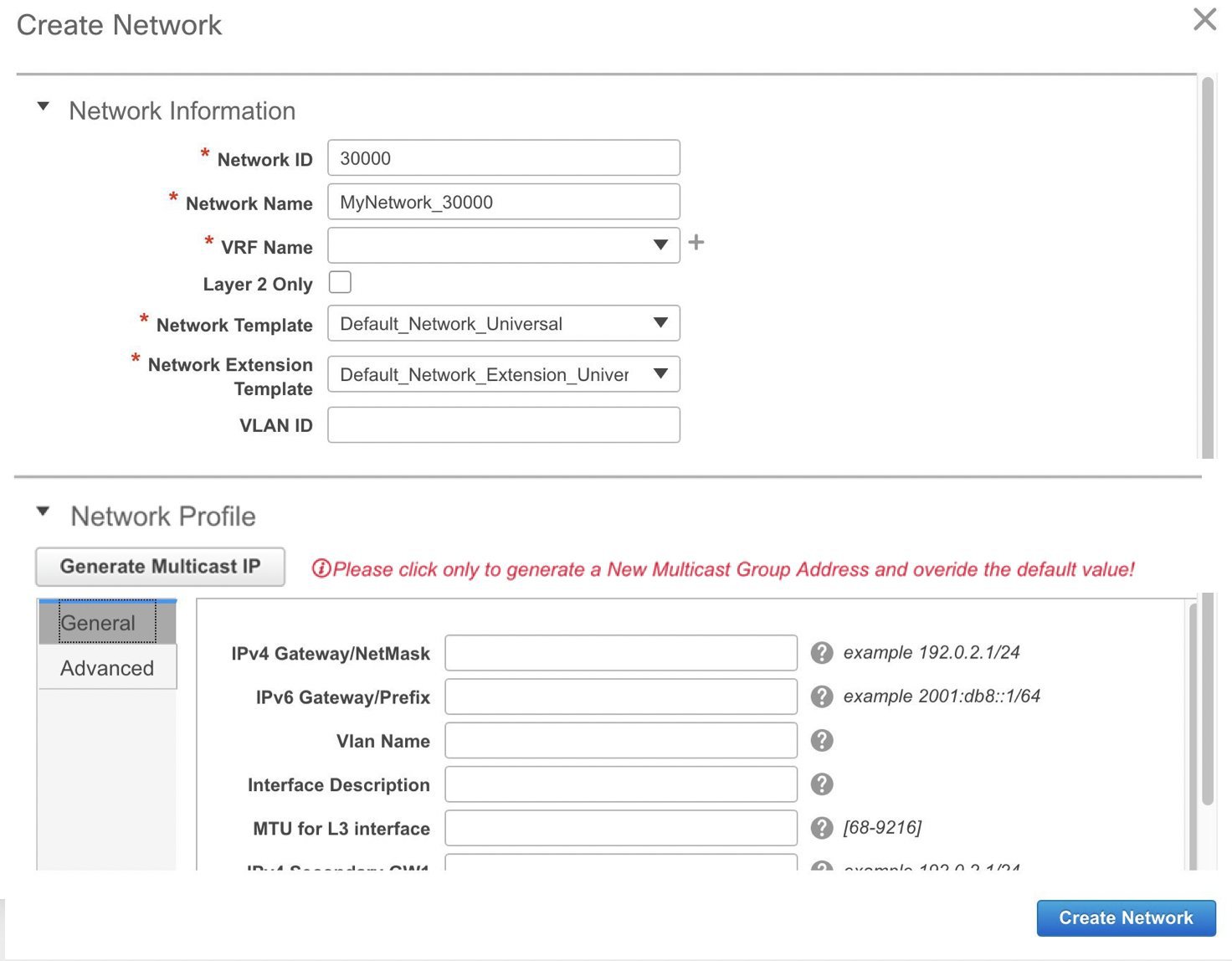
The fields in this screen are:
Network ID and Network Name: Specifies the Layer 2 VNI and name of the network. The network name should not contain any white spaces or special characters except underscore (_) and hyphen (-). The corresponding Layer 3 VNI (or VRF VNI) is generated along with VRF creation.
VRF Name: Allows you to select the Virtual Routing and Forwarding (VRF).
When no VRF is created, this field appears blank. If you want to create a new VRF, click the + button. The VRF name should not contain any white spaces or special characters except underscore (_), hyphen (-), and colon (:).
Layer 2 Only: Specifies whether the network is Layer 2 only.
Network Template: A universal template is autopopulated. This is only applicable for leaf switches.
Network Extension Template: A universal extension template is autopopulated. This allows you to extend this network to another fabric. The methods are VRF Lite, Multi Site, and so on. The template is applicable for border leaf switches and BGWs.
VLAN ID: Specifies the corresponding tenant VLAN ID for the network.
Network Profile section contains the General and Advanced tabs.
General tab
IPv4 Gateway/NetMask: Specifies the IPv4 address with subnet.
IPv6 Gateway/Prefix: Specifies the IPv6 address with subnet.
Specify the anycast gateway IP address for transporting the L3 traffic from a server belonging to MyNetwork_30000 and a server from another virtual network. By default the anycast gateway IP address is the same for MyNetwork_30000 on all switches of the fabric that have the presence of the network.
VLAN Name - Enter the VLAN name.
Interface Description: Specifies the description for the interface. This interface is a switch virtual interface (SVI).
MTU for the L3 interface - Enter the MTU for Layer 3 interfaces.
IPv4 Secondary GW1 - Enter the gateway IP address for the additional subnet.
IPv4 Secondary GW2 - Enter the gateway IP address for the additional subnet.
Advanced tab: Optionally, specify the advanced profile settings by clicking the Advanced tab:
ARP Suppression – Select the checkbox to enable the ARP Suppression function.
Ingress Replication - The checkbox is selected if the replication mode is Ingress replication.
Note
Ingress Replication is a read-only option in the Advanced tab. Changing the fabric setting updates the field.
Multicast Group Address- The multicast IP address for the network is autopopulated.
Multicast group address is a per fabric instance variable. The number of underlay multicast groups supported is only 128. If all networks are deployed on all switches, you need not use a different multicast group per L2 VNI or a network. Therefore, multicast group for all networks in a fabric remains same. If a new multicast group address is required, you can generate it by clicking the Generate Multicast IP button.
DHCPv4 Server 1 - Enter the DHCP relay IP address of the first DHCP server.
DHCPv4 Server 2 - Enter the DHCP relay IP address of the next DHCP server.
DHCPv4 Server VRF- Enter the DHCP server VRF ID.
Routing Tag – The routing tag is autopopulated. This tag is associated with each gateway IP address prefix.
TRM enable – Select the checkbox to enable TRM.
L2 VNI Route-Target Both Enable - Select the check box to enable automatic importing and exporting of route targets for all L2 virtual networks.
Enable L3 Gateway on Border - Select the checkbox to enable a Layer 3 gateway on the border switches.
A sample of the Create Network screen is given below.
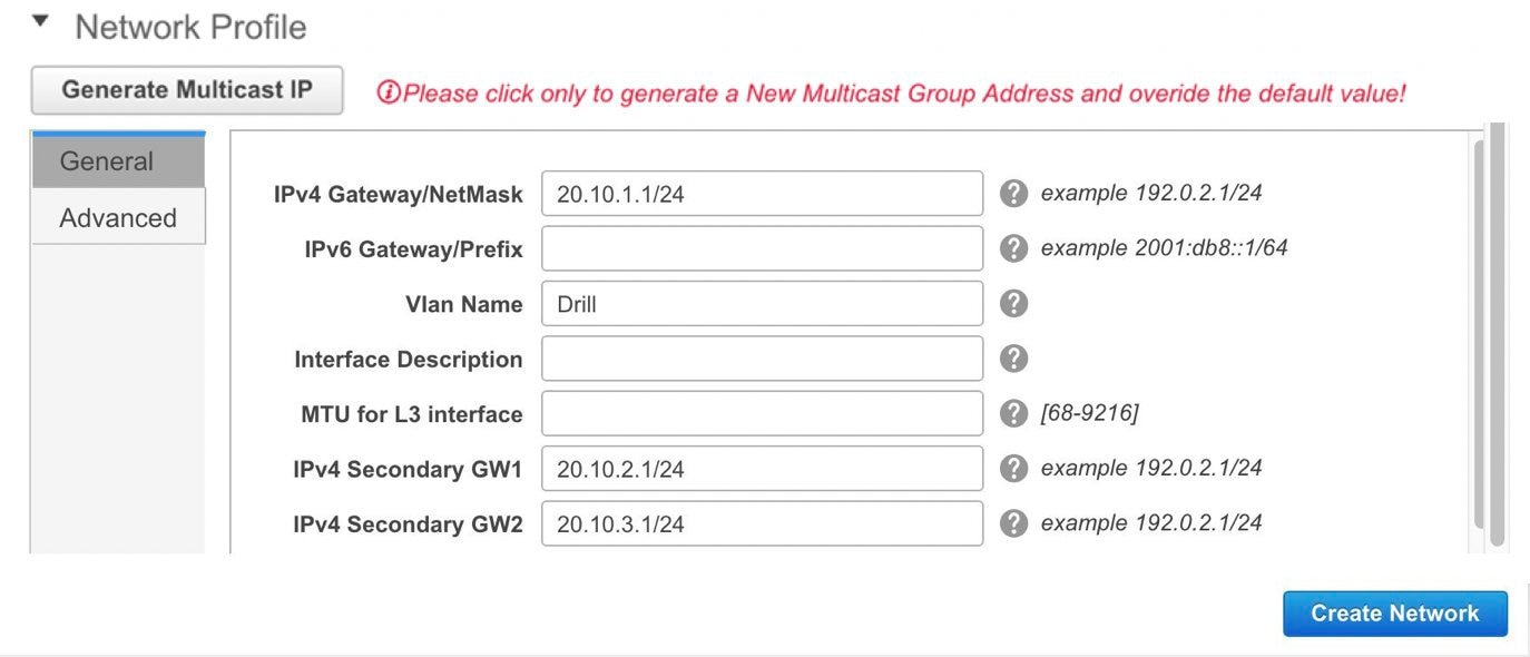
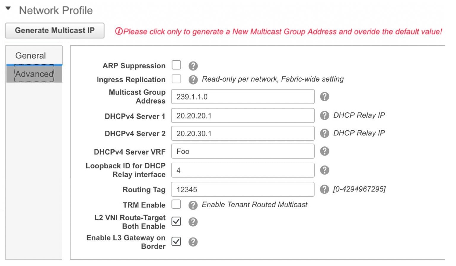
-
Click Create Network. A message appears at the bottom right part of the screen indicating that the network is created.
The new network appears on the Networks page that comes up.
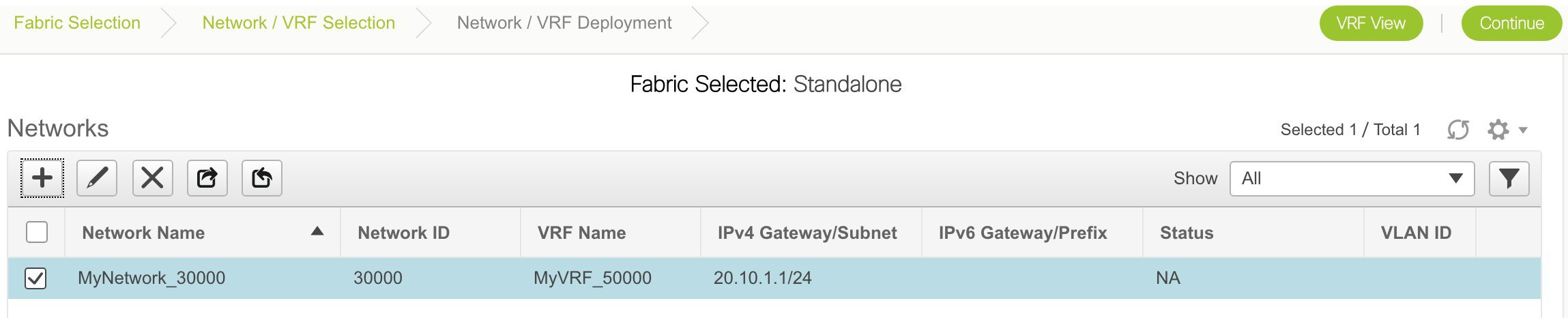
The Status is NA since the network is created but not yet deployed on the switches. Now that the network is created, you can create more networks if needed and deploy the networks on the devices in the fabric.
Export and Import Network Information
You can export network information to a .CSV file. The exported file contains information pertaining to each network, including the fabric it belongs to, the associated VRF, the network templates used to create the network, and all other configuration details that you saved during network creation.
In the Networks screen, click the Export icon to export network information as a .CSV file.
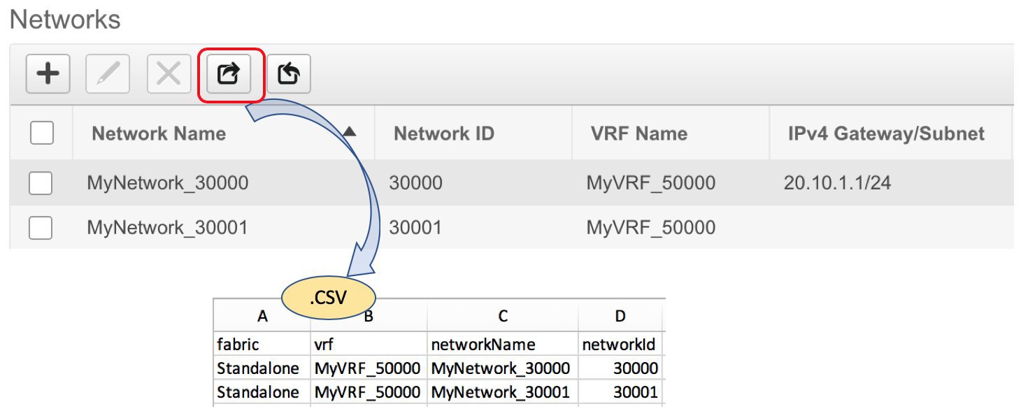
You can use the exported .CSV file for reference or use it as a template for creating new networks. To import networks, do the following:
-
Update new records in the .CSV file. Ensure that the networkTemplateConfig field contains the JSON Object. A message at the bottom right part of the screen displays errors and success messages. This screenshot depicts two new networks being imported.
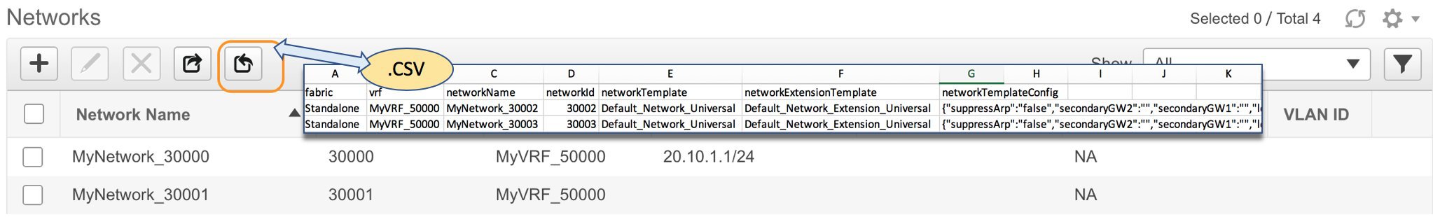
-
In the Networks screen, click the Import icon and import the .CSV file into DCNM.
You can see that the imported networks are displayed in the Networks screen.
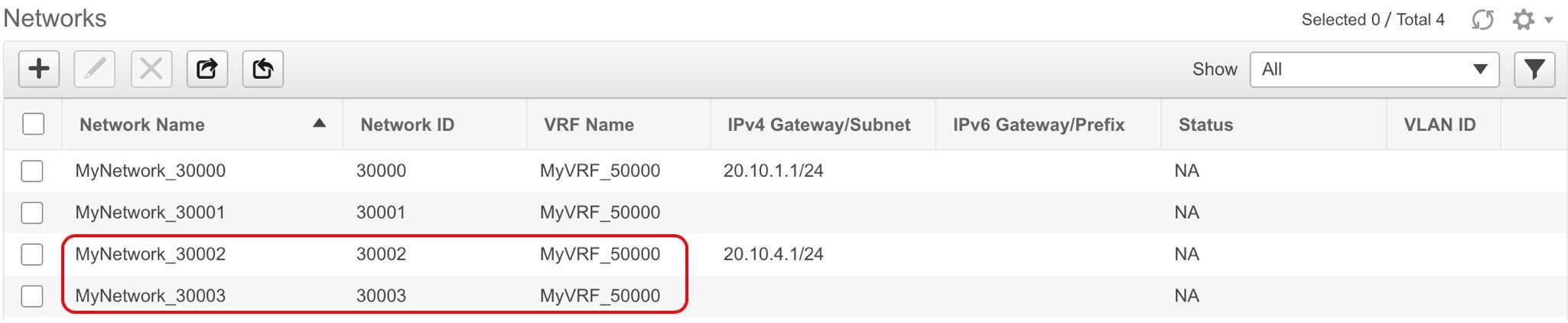
Editing Networks for the Standalone Fabric
Procedure
| Step 1 |
Click Control > Networks. |
||
| Step 2 |
Choose a fabric from the SCOPE drop-down list. |
||
| Step 3 |
Choose a network. |
||
| Step 4 |
Click the Edit icon. |
||
| Step 5 |
Update the fields in the General and Advanced tabs of the Network Profile area as needed.
|
||
| Step 6 |
Click Save at the bottom right part of the window to save the updates. |
Creating VRFs for the Standalone Fabric
-
Click Control > VRFs (under Fabrics submenu).
The VRFs screen comes up.
-
Choose the correct fabric from SCOPE. When you select a fabric, the VRFs screen refreshes and lists VRFs of the selected fabric.
-
Click the + button to add VRFs to the Standalone fabric. The Create VRF screen comes up. Most of the fields are autopopulated.
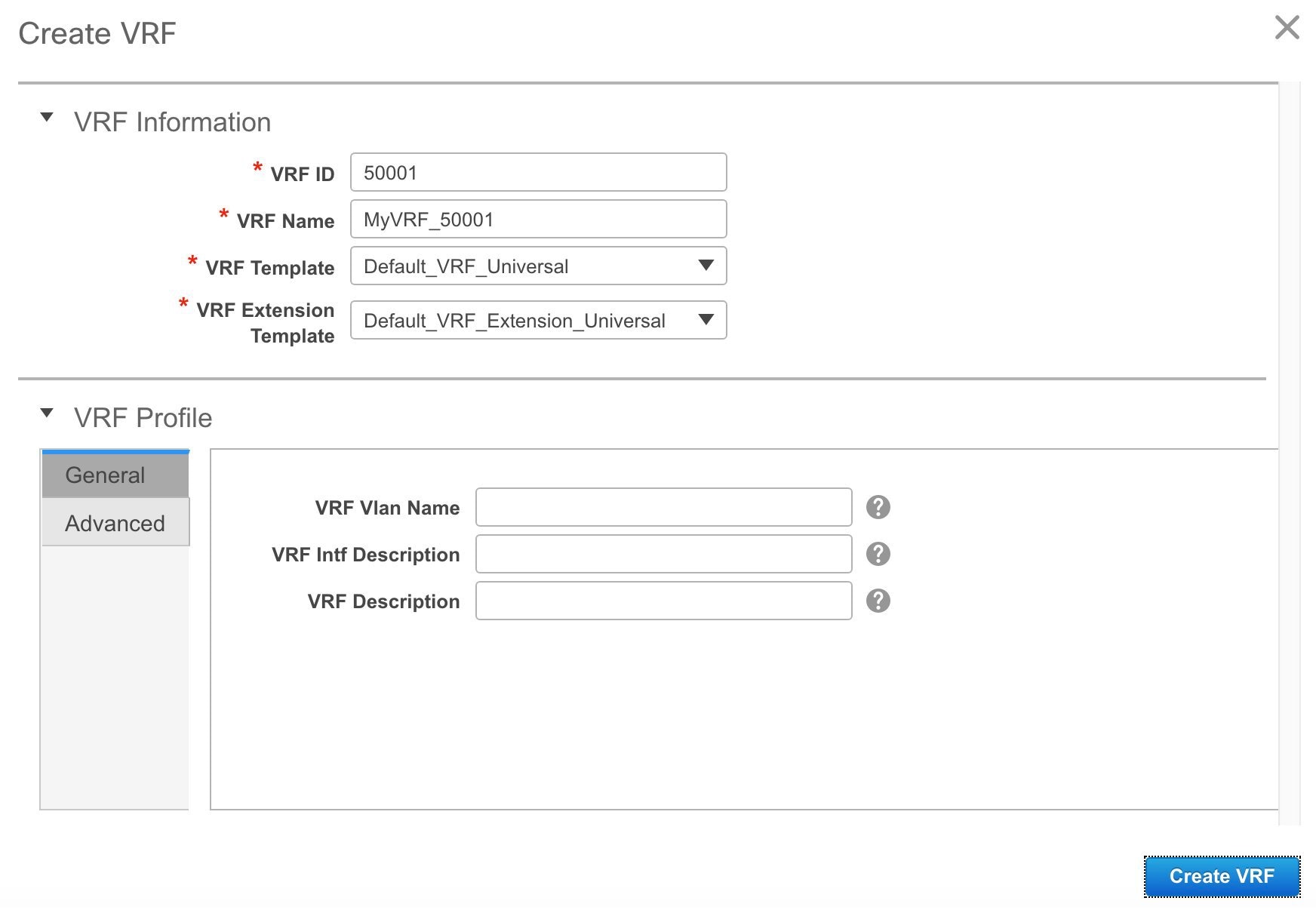
The fields in this screen are:
VRF ID and VRF Name: The ID and name of the VRF.
Note
For ease of use, the VRF creation option is also available while you create a network.
VRF Template: This template is applicable for VRF creation, and only applicable for leaf switches.
VRF Extension Template: The template is applicable when you extend the VRF to other fabrics, and is applicable for border devices.
Fill the fields in the VRF Profile section.
General tab – Enter the VLAN ID of the VLAN associated with the VRF, the corresponding Layer 3 virtual interface, and the VRF ID.
Advanced tab – The fields in the tab are autopopulated.
Routing Tag – If a VLAN is associated with multiple subnets, then this tag is associated with the IP prefix of each subnet. Note that this routing tag is associated with overlay network creation too.
Redistribute Direct Route Map – Specifies the route map name for redistribution of routes in the VRF.
Max BGP Paths and Max iBGP Paths – Specifies the maximum BGP and iBGP paths.
TRM Enable – Select the checkbox to enable TRM.
If you enable TRM, then the RP address, the RP loopback ID and the underlay multicast address must be entered.
Is RP External – Enable this checkbox if the RP is external to the fabric.
RP Address and RP Loopback ID – Specifies the loopback ID and IP address of the RP.
Underlay Multicast Address – Specifies the multicast address associated with the VRF. The multicast address is used for transporting multicast traffic in the fabric underlay.
Note
The multicast address in the Multicast address for TRM field in the fabric settings screen is populated in this field.
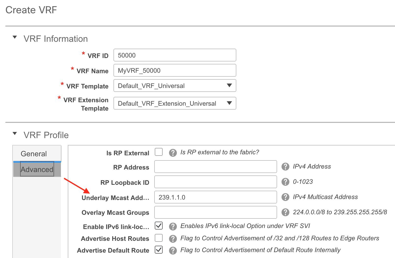
Overlay Multicast Groups – Specifies the multicast address for the VRF, used in the fabric overlay.
Enable IPv6 link-local Option – Enables the IPv6 link-local option under the VRF SVI.
Advertise Host Routes – Enable the checkbox to control advertisement of /32 and /128 routes to Edge Routers.
Advertise Default Route – Enable the checkbox to control advertisement of default routes internally.
To allow inter-subnet communication between end hosts in different VXLAN fabrics, where the subnets are present in both fabrics, you must disable the Advertise Default Route feature (clear the Advertise Default Route checkbox) for the associated VRF. This will result in /32 routes for hosts being seen in both fabrics. For example, Host1 (VNI 30000, VRF 50001) in Fabric1 can send traffic to Host2 (VNI 30001, VRF 50001) in Fabric2 only if the host route is present in both fabrics. When a subnet is present in only one fabric then default route is sufficient for inter-subnet communication.
Sample screenshots of the Create VRF screen:
Advanced tab:
-
Click Create VRF.
The MyVRF_50001 VRF is created and appears on the VRFs page.
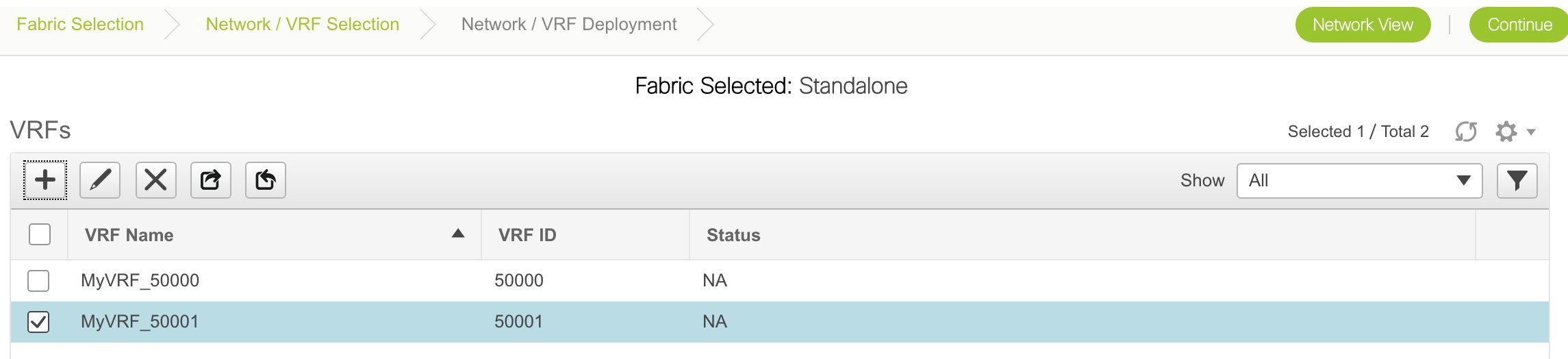
Export and Import VRF Information
You can export VRF information to a .CSV file. The exported file contains information pertaining to each VRF, including the fabric it belongs to, the templates used to create the VRF, and all other configuration details that you saved during VRF creation.
In the VRFs screen, click the Export icon to export VRF information as a .CSV file.
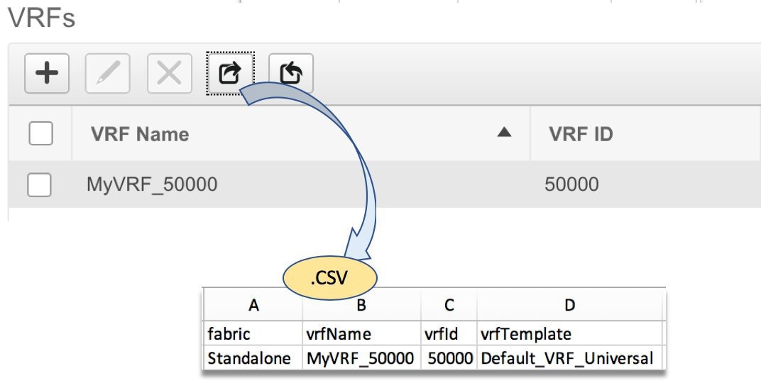
You can use the exported .CSV file for reference or use it as a template for creating new VRFs. To import VRFs, do the following:
-
Update new records in the .CSV file. Ensure that the vrfTemplateConfig field contains the JSON Object.
-
In the VRFs screen, click Import icon and import the .CSV file into DCNM.
A message at the bottom right part of the screen displays errors and success messages. This screenshot depicts a new VRF being imported.
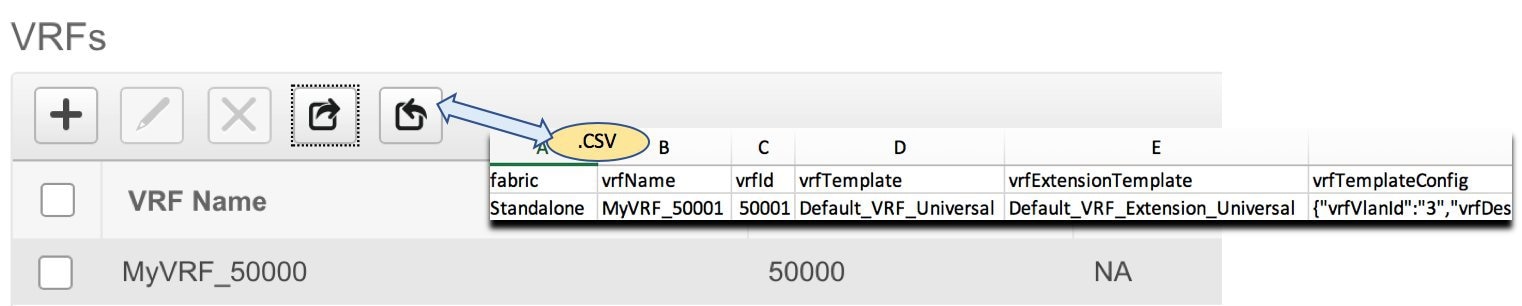
You can see that the imported VRF is displayed in the VRFs screen.
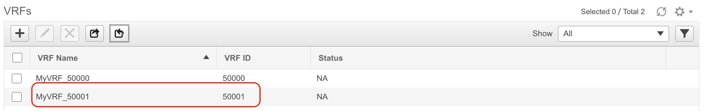
Editing VRFs for the Standalone Fabric
-
Choose the correct fabric from SCOPE. When you select a fabric, the VRFs screen refreshes and lists VRFs of the selected fabric.
-
From the Select a Fabric drop-down list, select the fabric Standalone, and click Continue on the top right part of the screen. The Networks page is displayed.
-
Click the VRF View at the top right part of the screen. The VRFs page appears.
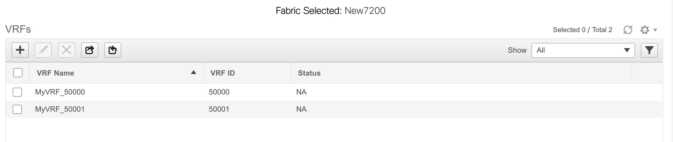
-
Select the VRF and click the Edit option at the top left part of the screen. The Edit VRF screen comes up.
-
Update the fields in the General and Advanced tabs of the VRF Profile section as needed.
-
Click Save at the bottom right part of the screen to save the updates.
Deploying Networks for the Standalone and MSD Fabrics
Before you begin: Ensure that you have created networks for the fabric.
-
Click Control > Networks (under Fabrics submenu).
The Networks screen comes up.
-
Choose the correct fabric from SCOPE. When you select a fabric, the Networks screen refreshes and lists networks of the selected fabric.
-
Select networks that you want to deploy. In this case, select the checkboxes next to both the networks and click Continue at the top right part of the screen.
The Network Deployment page appears. On this page, you can see the network topology of the Standalone fabric.
You can deploy networks simultaneously on multiple switches. The selected devices should have the same role (Leaf, Border Gateway, and so on).
Note
In an MSD fabric, all member fabrics are visible from this screen.
At the bottom right part of the screen, the color codes that represent different stages of deployment are displayed. The color of the switch icons changes accordingly. Blue for Pending state, yellow for In Progress when the provisioning is in progress, green when successfully deployed, and so on. From DCNM 11.3(1), the pending state indicates that there is a pending deployment or pending recomputation. You can click on the switch and review the pending deployments using Preview or Deploy Config options, or click Save & Deploy to recompute the state of the switch.
The overlay networks (/VRFs) provisioning status is context-specific. It is a combination of networks that you chose for provisioning and the relevant switches in the topology. In this example, it means that the networks MyNetwork_30000 and MyNetwork_30001 are yet to be deployed on any switch in this fabric.
Undiscovered cloud display – To display (or not display) an Undiscovered cloud in this screen, click the cloud icon in the vertical panel, at the top-right part of the screen. When you click the icon, the Undiscovered cloud and its links to the fabric topology are not displayed. Click the icon again to display the Undiscovered cloud.
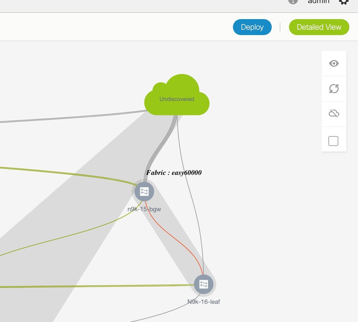
You can move the topology around the screen by clicking the left mouse button on the screen and moving it in the direction you desire. You can enlarge or shrink the switch icons proportionately by moving the cursor roller. You can also use corresponding alternatives on the touchpad.
-
Click ... in the Interfaces column.
The Interfaces box opens up. It lists interfaces or port channels. You can select interfaces/port channels to associate them with the selected network. For each interface, port type and description, channel number and connected neighbor interface details are displayed.
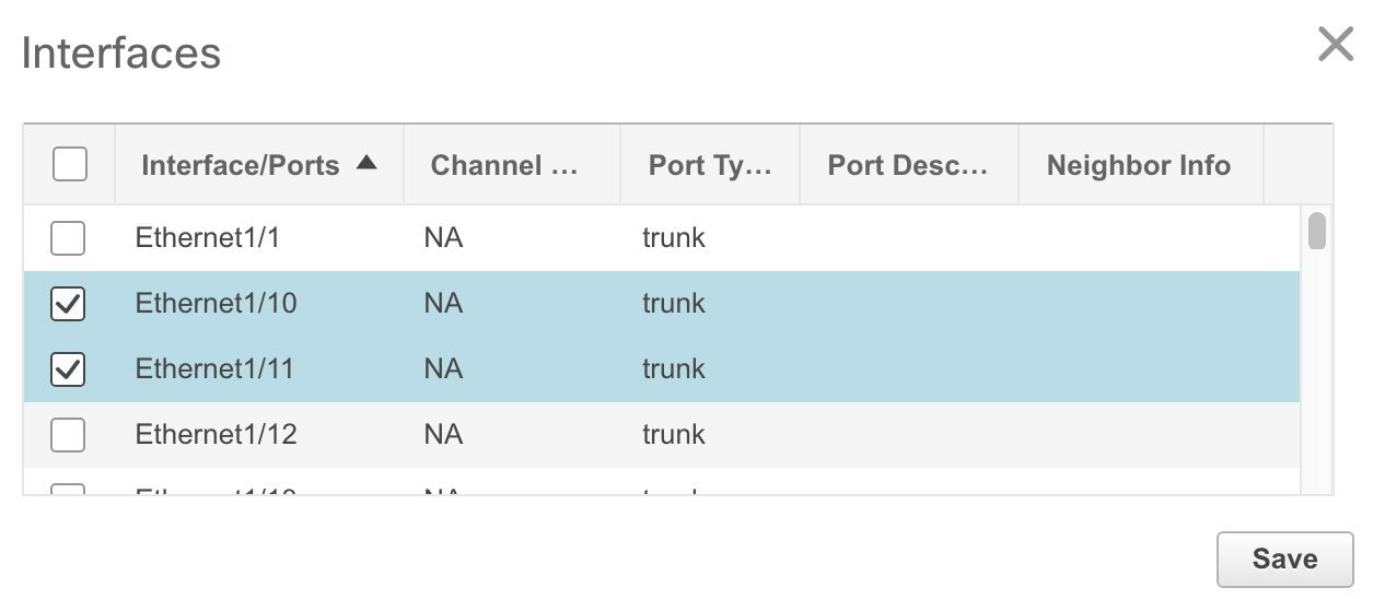
-
Double-click a switch to deploy the networks on it. For deployment of networks on multiple switches, click Multi-Select from the panel at the top right part of the screen (the topology freezes to a static state), and drag the cursor across the switches.
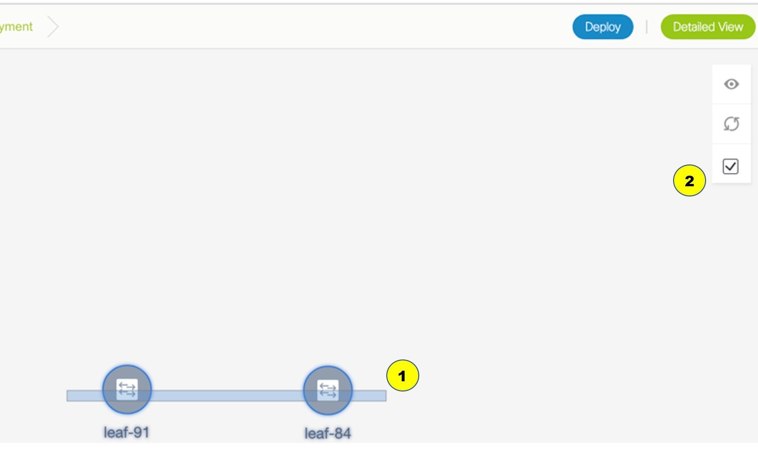
Immediately the Network Attachment dialog box appears.
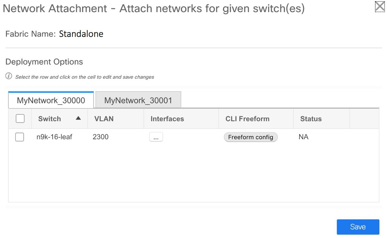
A tab represents each network (the first network is displayed by default) that is being deployed. In each network tab, the switches are displayed. Each row represents a switch.
Click the checkbox next to the Switch column to select all switches. The network is ready to be provisioned on the switches.
VLAN - Update the VLAN ID if needed.
When you update a VLAN ID and complete the network deployment process, the old VLAN is not automatically removed. To complete the process, you should go to the fabric topology screen (click Control > Fabric Builder and click within the corresponding fabric box to go to the screen) and use the Save and Deploy option.
When updating the VLAN ID for a given network, the original VLAN ID is not automatically removed from the attached trunk interface. In order to remove the old or original VLAN ID, you must perform Save and Deploy + Config Deploy operation from within the fabric in Fabric Builder. For this, go to the fabric topology screen (click Control > Fabric Builder and click within the corresponding fabric box to go to the screen) and execute the Save and Deploy operation. Verify that config compliance is removing the expected config, then execute Deploy Config operation to remove the configs.
Interfaces – Click … in the column to add interfaces associated with the selected network.
VLAN to trunk port mapping – The selected trunk ports include the VLAN as an allowed VLAN on the port.
VLAN to vPC domain mapping - If you want to associate the VLAN to port channels of a vPC domain, add the port channels from the list of interfaces. The vPC port channels include the VLAN as an allowed VLAN.
Freeform configurations – Click Freeform config to enable additional configurations on the switch. After the configurations are saved, the Freeform config button gets highlighted.
-
Select the other network tab and make the same selections.
-
Click Save (at the bottom right part of your screen) to save the configurations.
Note
Addition and removal of interfaces are displayed in the Interfaces column of the Switches Deploy screen. Though the interface-related updates (like addition or removal of trunk ports) are provisioned on the switches, the correct configurations will not reflect in the preview screen. When you add or remove a trunk or access port, the preview shows the addition or removal of configurations for the interface under that network.
The topology window appears again. Click Refresh in the vertical panel at the top right part of the screen. The blue color on the switch icons indicates that the deployment is pending. From DCNM 11.3(1), the pending state indicates that there is a pending deployment or pending recomputation. You can click on the switch and review the pending deployments using Preview or Deploy Config options, or click Save & Deploy to recompute the state of the switch.
-
Preview the configurations by clicking Preview (the eye icon above the Multi-Select option). Since MyNetwork_30000 and MyNetwork_30001 are networks of VRF 50000, the configurations contain VRF configurations followed by the network configurations.
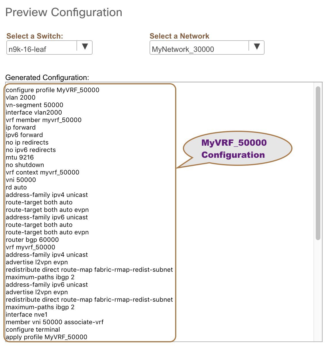
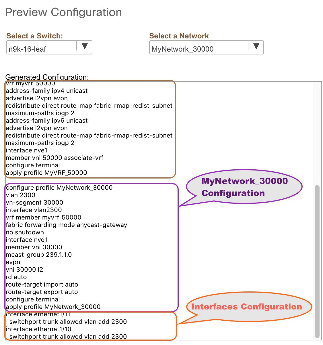
On the preview screen, you can select from the Select a switch and Select a network drop-down boxes at the top of the screen to view other network configurations.
After checking the configurations, close the screen. The Topology screen appears again.
-
Click Deploy on the top right part of the screen. The color of the switch icons changes to yellow and a message appears at the bottom right part of the screen indicating that the deployment is in progress. After the networks' deployment is complete, the color of the switch icons changes to green, indicating successful deployment.
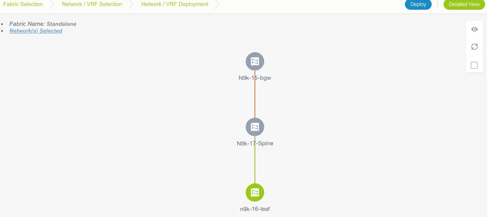
Note
The status of the switch is determined by the aggregated status of the selected networks or VRFs in the following hierarchy: Pending, In Progress, Out-of-Sync/Failed, In Sync/Success, and Unknown/NA. For example, if any one of the networks or VRFs is in the Out-of-Sync/Failed status and others are not in the Pending or In Progress status, then the switch status is Out-of-Sync/Failed. The default status is Unknown/NA, when the status is not known.
Go to the Networks page to view the individual status for all networks.
Network Deployment for an MSD Fabric
Consider a scenario wherein you are deploying the same networks on different member fabric border devices. You can choose one fabric, deploy networks on its border devices, and then choose the second fabric and deploy networks.
Alternatively, you can choose the MSD fabric, and deploy the networks from a single topology view of all member fabric border devices.
This is a topology view of an MSD fabric wherein the two member fabrics topologies and their connections are depicted. You can deploy networks on the BGWs of the fabrics at once.
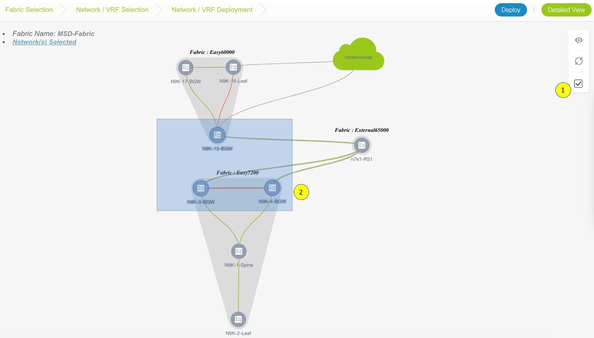
Detailed View
You can also use the Detailed View option to deploy networks and VRFs. Click Detailed View at the top right part of the screen. The Detailed View window appears. This lists the networks in a tabular view.
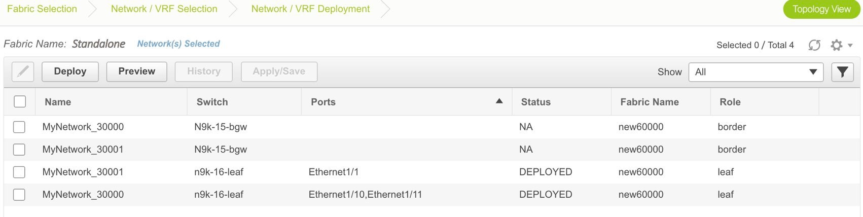
The options:
Edit - Select a network and click the Edit icon at the top left part of the screen.
Note |
If you select one network/switch entry and click on Edit, the Network Attach dialog box appears. To maintain consistency across the Topology View and Detailed View screens, the Network Attach screen displays all networks, and not just the selected network/switch. |
Preview – Click Preview to preview configurations before deployment. You can only preview pending configurations, and not uninitiated or deployed configurations.
Deploy – Click Deploy to provision networks onto the switches.
History – Select a row and click History to view the configuration instances and status. Network and VRF-wise configurations are displayed. Click in the Status column of any instance for more details.
The fields in the table contain the configuration instance in each row, the associated switch and fabric names, the switch role, trunk ports (if any), and the deployment status.
Apply/Save – Selecting a network and clicking Apply/Save will select a switch for the network to be deployed on.
On the Detailed View page, the network profile configuration history is displayed. If you have associated specific trunk interfaces to that network, then the interface configuration is displayed as a separate configuration instance.
Note |
When you upgrade from an earlier release (such as DCNM 10.4[2]) to the DCNM 11.0(1) release, overlay networks and VRFs deployment history information from the earlier DCNM release is not retained. |
Deploying VRFs for the Standalone and MSD Fabrics
-
Choose the correct fabric from SCOPE. When you select a fabric, the VRFs screen refreshes and lists VRFs of the selected fabric.
-
Select check boxes next to the VRFs that you want to deploy and click Continue at the top right part of the screen.
The VRF Deployment screen appears. On this page, you can see the topology of the Standalone fabric. The following example shows you how to deploy the VRFs MyVRF_50000 and MyVRF_50001 on the leaf switch. You can deploy VRFs simultaneously on multiple switches but of the same role (Leaf, Border Gateway, and so on).
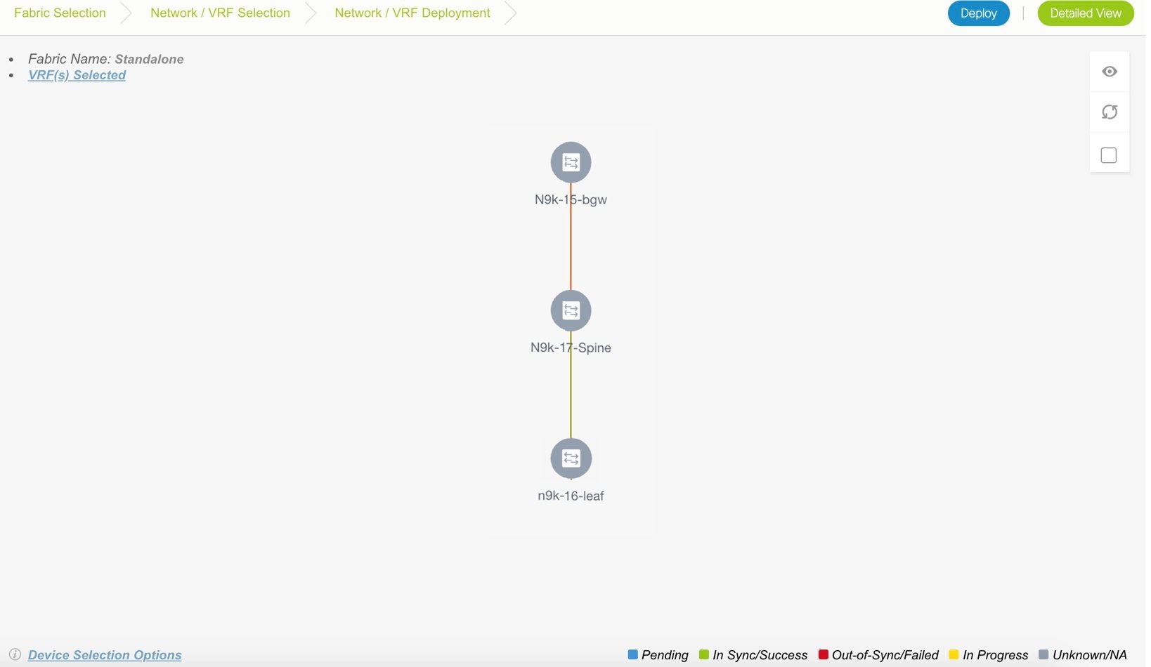
At the bottom right part of the screen, the color codes that represent different stages of deployment are displayed. The color of the switch icons changes accordingly. Blue for Pending state, yellow for In Progress state when the provisioning is in progress, red for failure state, green when successfully deployed, and so on. From DCNM 11.3(1), the pending state indicates that there is a pending deployment or pending recomputation. You can click on the switch and review the pending deployments using Preview or Deploy Config options, or click Save & Deploy to recompute the state of the switch.
The overlay networks (or VRFs) provisioning status is context-specific. It is a combination of VRFs that you chose for provisioning and the relevant switches in the topology. In this example, it means that the VRFs are yet to be deployed on any switch in this fabric.
Undiscovered cloud display – To display (or not display) an Undiscovered cloud in this screen, click the cloud icon in the vertical panel, at the top-right part of the screen. When you click the icon, the Undiscovered cloud and its links to the fabric topology are not displayed. Click the icon again to display the Undiscovered cloud.
You can move the topology around the screen by clicking the left mouse button on the screen and moving it in the direction you desire. You can enlarge or shrink the switch icons proportionately by moving the cursor roller. You can also use corresponding alternatives on the touchpad.
-
Double-click a switch to deploy VRFs on it. The VRF Attachment screen comes up.
Note
For deployment of VRFs on multiple switches, click the Multi-Select option from the panel at the top right part of the screen (This freezes the topology to a static state), and drag the cursor across the switches.
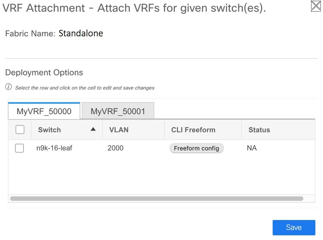
A tab represents each VRF that is being deployed (the first selected VRF is displayed by default). In each VRF tab, the selected switches are displayed. Each row represents a switch.
VLAN ID - Click within the VLAN column to update the VRF VLAN ID, if needed.
Freeform configurations – Click Freeform config to enable additional configurations on the switch. After you save freeform configurations, the Freeform config button gets highlighted.
Click the checkbox next to the Switch column to select all switches. VRF MyVRF_50000 is ready to be provisioned on the switch
-
Select the other VRF tab and make the same selections.
-
Click Save (at the bottom right part of your screen) to save VRF configurations.
The topology screen comes up again. Click the Refresh button in the vertical panel at the top right part of the screen. The blue color on the switch icons indicates that the deployment is pending. From DCNM 11.3(1), the pending state indicates that there is a pending deployment or pending recomputation. You can click on the switch and review the pending deployments using Preview or Deploy Config options, or click Save & Deploy to recompute the state of the switch.
Preview the configurations by clicking the Preview button (the eye icon above the Multi-Select option).
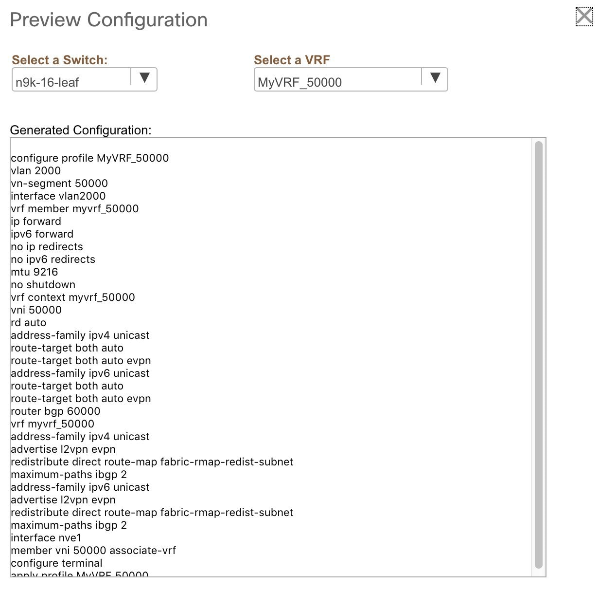
After checking the configurations, close the screen. The Topology View screen appears.
-
Click the Deploy button on the top right part of the screen. The color of the switch icons changes to yellow and a message appears at the bottom right part of the screen indicating that the deployment is in progress. After the VRF deployment is complete, the color of the switch icons changes to green, indicating successful deployment.
VRFs Deployment for an MSD Fabric
Consider a scenario wherein you are deploying the same VRFs on different member fabric border devices. You can choose one fabric, deploy VRFs on its border devices, and then choose the second fabric and deploy the VRFs.
Alternatively, you can choose the MSD fabric, and deploy the VRFs from a single topology view of all member fabric border devices at once.
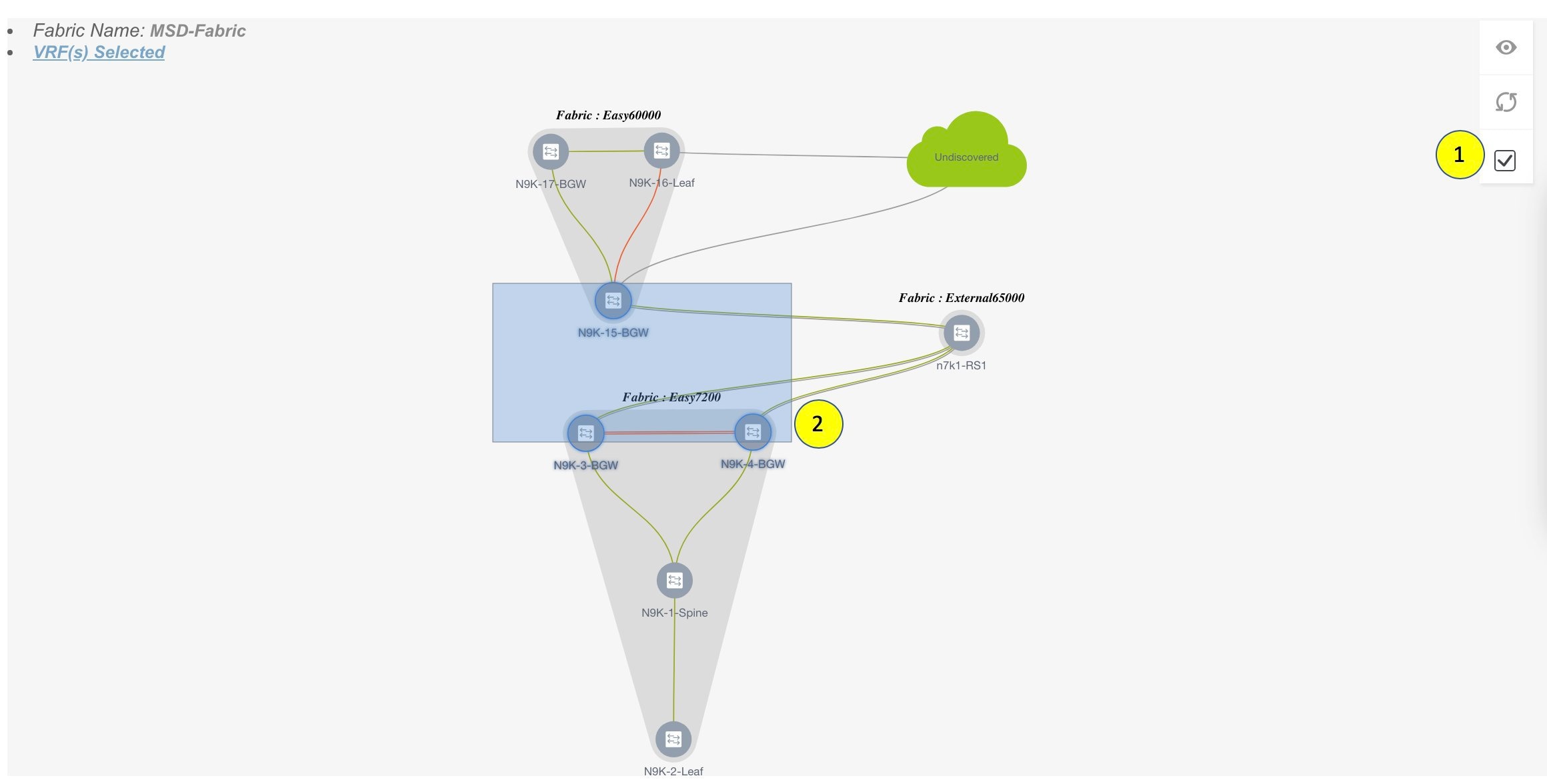
Detailed View
You can also use the Detailed View button to deploy networks and VRFs.
Click Detailed View at the top right part of the screen. The Detailed View screen comes up. This lists the VRFs in a tabular view.
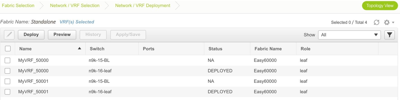
The options:
Edit - Select a VRF and click the Edit icon at the top left part of the screen.
Note |
If you select one VRF/switch entry, the VRF Attach screen comes up. To maintain consistency across the Topology View and Detailed View screens, the VRF Attach screen displays all VRFs, and not just the selected VRF/switch entry. |
Preview – Click Preview to preview configurations before deployment. You can only preview pending configurations, and not uninitiated or deployed configurations.
Deploy – Click Deploy to provision VRFs onto the switches.
History – Select a row and click History to view the configuration instances and status. Network and VRF-wise configurations are displayed. Click in the Status column of any instance for more details.
The fields in the table contain the configuration instance in each row, the associated switch and fabric names, the switch role, and the deployment status.
Apply/Save – Selecting a VRF and clicking Apply/Save will select a switch for the VRF to be deployed on.
Note |
When you upgrade from an earlier release (such as DCNM 10.4[2]) to the DCNM 11.0(1) release, overlay networks and VRFs deployment history information from the earlier DCNM release is not retained. |
Undeploying Networks for the Standalone Fabric
You can undeploy VRFs and networks from the deployment screen. The DCNM screen flow for undeployment is similar to the deployment process flow. Go to the deployment screen (Topology View) to undeploy networks:
-
Click Control > Networks (under Fabrics submenu).
The Networks screen comes up.
-
Choose the correct fabric from SCOPE. When you select a fabric, the Networks screen refreshes and lists networks of the selected fabric.
-
Select the networks that you want to undeploy and click Continue. The topology view comes up.
-
Select the Multi-Select button (if you are undeploying the networks from multiple switches), and drag the cursor across switches with the same role. The Network Attachment screen comes up.
(For a single switch, double-click the switch and the Network Attachment screen comes up).
(For a single switch, double-click the switch and the Switches Deploy screen comes up).
-
In the Network Attachment screen, the Status column for the deployed networks is displayed as DEPLOYED. Clear the check boxes next to the switches, as needed. Ensure that you repeat this on all tabs since each tab represents a network.
-
Click Save (at the bottom right part of the screen) to initiate the undeployment of the networks. The Topology View comes up again.
Note
Alternatively, you can click the Detailed View button to undeploy networks.
-
Refresh the screen, preview configurations if needed and click Deploy to remove the network configurations on the switches. After the switch icons turn green, it indicates successful undeployment.
-
Go to the Networks page to verify if the networks are undeployed.
Undeploying VRFs for the Standalone Fabric
You can undeploy VRFs from the deployment screen. The DCNM screen flow for undeployment is similar to the deployment process flow.
-
Choose Control > Fabrics > VRFs.
-
Choose the correct fabric from SCOPE. When you select a fabric, the VRFs screen refreshes and lists networks of the selected fabric.
-
Select the VRFs that you want to undeploy and click Continue. The Topology View page comes up.
-
Select the Multi-Select option (if you are undeploying the VRFs from multiple switches), and drag the cursor across switches with the same role. The VRF Attachment screen comes up.
(For a single switch, double-click the switch and the VRF Attachment screen comes up).
-
In the Switches Deploy screen, the Status column for the deployed VRFs is displayed as DEPLOYED. Clear the check boxes next to the switches, as needed. Ensure that you repeat this on all tabs since each tab represents a VRF.
-
Click Save (at the bottom right part of the screen) to initiate the undeployment of the VRFs. The topology view comes up again.
Note
Alternatively, you can click the Detailed View button to undeploy VRFs.
-
Refresh the screen, preview configurations if needed and click Deploy to remove the VRF configurations on the switches. After the switch icons turn green, it indicates successful undeployment.
-
Go to the VRFs page to verify if the networks are undeployed.
Deleting Networks and VRFs
If you want to delete networks and corresponding VRFs in the MSD fabric, follow this order:
-
Undeploy the networks, if not already done.
-
Delete the networks.
-
Undeploy the VRFs, if not already done.
-
Delete the VRFs.
Restore Fabric
Cisco DCNM supports configuration restore at fabric level. Take a backup of the configuration to restore it.
Procedure
| Step 1 |
Choose Control > Fabrics > Fabric Builder and select a fabric. |
||
| Step 2 |
Select Restore Fabric from the Actions menu. Restore Fabric window appears. |
||
| Step 3 |
Choose the time for which you want to restore the configuration. Valid values are 1m, 3m, 6m, YTD, 1y, and All. You can zoom into the graph. By default 1m, which is one month, backup information will be displayed. You can also select a custom date range. The backup information includes the backup date, total number of devices, number of devices in sync, and the number of devices out of sync. |
||
| Step 4 |
Choose the backup you want to restore. You can choose the automatic or manual backup. The automatic backup that is initiated from the Configuration Backup tab in the Fabric Settings dialog box. The manual backup is initiated by clicking Backup Now from the Actions pane in the fabric topology window. |
||
| Step 5 |
Click Next to see the selected backup information of the devices in sync. The switch name, switch serial number, IP address, and the delta configuration details of the devices appear.
|
||
| Step 6 |
Click Get Config to preview the configuration details. Config Preview window appears, which has two tabs.
|
||
| Step 7 |
Go back to View Backup Summary window. |
||
| Step 8 |
Click Restore Intent to proceed with the restoring. Restore Status window appears. You can view the status of Validating Backup, Restoring fabric intent, Restoring underlay intent, Restoring interface intent, and Restoring overlay intent. The valid values for the status of any action will be In Progress, Pending, or Failed.
|
||
| Step 9 |
Click Next after the intent is restored. Configuration Preview window appears. You can view the details of the switch name, IP address, switch serial number, preview configuration, status, and the progress in this window. |
||
| Step 10 |
Click Deploy to deploy the restored configuration. Configuration Deployment Status window appears. You can view the details of the switch name, IP address, status, status description, and the progress. |
||
| Step 11 |
Click Close after the restoring process is complete. |
Deleting a VXLAN BGP EVPN Fabric
Choose Control > Fabric Builder. On the Fabric Builder page, click X on the rectangular box that represents the fabric. Ensure the following before deleting a fabric.
-
Fabric devices should not be in transition such as migration into or out of the fabric, ongoing network or VRF provisioning, and so on. Delete a fabric after the transition is complete.
-
Remove devices that are still attached to the fabric. Remove non-Cisco Nexus 9000 Series switches first and then remove the 9000 Series switches.
Post DCNM 11.3(1) Upgrade for VXLAN BGP EVPN, External, and MSD Fabrics
Note the following guidelines after you upgrade to the DCNM Release 11.3(1):
-
As part of the upgrade from an earlier DCNM release, the fabric and associated templates are carried over to the DCNM Release 11.3(1).
-
In DCNM Release 11.3(1), some of the policy templates from the older DCNM releases are deprecated. After an upgrade to DCNM Release 11.3(1), if the deprecated policy templates are not in use, they are automatically removed from the template library. This removal does not affect any operations and helps in reducing the number of policies displayed in the DCNM template library.
-
Some of the legacy fabric templates have been deprecated and they are not supported in the DCNM Release 11.3(1). The fabrics that are using the legacy templates must be updated to use their new version.
Perform the following steps to use the new templates:
-
Edit the settings of each fabric by updating the old fabric template with the equivalent new fabric template.
The following table shows the old and new fabric template names in DCNM.
Old Template Fabric Name
New Template Fabric Name
Easy_Fabric
Easy_Fabric_11_1
External_Fabric
External_Fabric_11_1
MSD_Fabric
MSD_Fabric_11_1
-
Navigate to each fabric in the Topology view, and click Save & Deploy to deploy any changes.
If you encounter any new or unexpected pending configurations after you click Save & Deploy, refer Configuration Compliance in DCNM.

Caution
Some configuration changes can be expected as part of this step. Therefore, perform it only during a scheduled maintenance window.
-
-
If the fabric is already using the correct template with the 11_1 suffix, no additional action is needed. You can continue to use the fabric functions. However, if you want to use the new features in DCNM Release 11.3(1), you must update the fabric settings as needed and click Save & Deploy.
-
Post DCNM upgrade from Release 11.1(1) or 11.2(1) to Release 11.3(1), you could see the following diff if the fabric has a border device (border, border spine, border gateway, etc):
route-map extcon-rmap-filter-v6 deny 20
  no match ip address prefix-list host-route-v6
route-map extcon-rmap-filter-v6 deny 20
  match ipv6 address prefix-list host-route-v6
The above config is expected and it is meant to correct the route-map definition. Deployment of this diff will correct the switch configuration. If the fabric was created as Greenfield before upgrade, no additional action is needed. If the fabric was created as Brownfield before upgrade with the wrong route-map configuration on the device, this config will be captured in a switch_freeform policy. Post upgrade, you should edit the freeform policy to remove the CLI match ip address prefix-list host-route-v6 before the deployment.
Changing ISIS Configuration from Level 1 to Level 2
This procedure shows how to change ISIS configuration on switches from Level 1 to Level 2 in a VXLAN fabric deployment.
-
Choose Control > Fabrics > Fabric Builder.
-
Click a fabric in the Fabric Builder window.
-
Click Tabular view under Actions menu.
-
Search for all the base_isis policies in the Template search field.
-
Select all the base_isis policies and click the Delete icon to delete policies
-
Click Save & Deploy.
After all the base_isis policies are deleted, DCNM considers the migrated brownfield fabric as a greenfield fabric and creates the base_isis_level2 policies on the switches.
Configuration Compliance in DCNM
The entire intent or expected configuration defined for a given switch is stored in DCNM. When you want to push this configuration down to one or more switches, the configuration compliance (CC) module is triggered. CC takes the current intent, the current running configuration, and then comes up with the set of configurations that are required to go from the current running configuration to the current expected config so that everything will be IN-SYNC.
When performing a software or firmware upgrade on the switches, the current running configuration on the switches is not changed. Post upgrade, if CC finds that the current running configuration does not have the current expected configuration or intent, it reports an OUT-OF-SYNC status. There is no auto deployment of any configurations. You can preview the diffs that will get deployed to get one or more devices back IN-SYNC.
With CC, the sync is always from the DCNM to the switches. There is no reverse sync. So, if you make a change out-of-band on the switches that conflicts with the defined intent in DCNM, CC captures this diff, and indicates that the device is OUT-OF-SYNC. The pending diffs will undo the configs done out-of-band to bring back the device IN-SYNC. Note that such conflicts due to out-of-band changes are captured by the periodic CC run that occurs every 60 mins by default, or when you click the RESYNC option either on a per fabric or per switch basis. Note that you can also capture the out-of-band changes for the entire switch by using the CC REST API. For more information, see Cisco DCNM REST API Guide, Release 11.2(1).
From Cisco DCNM Release 11.2(1), to improve ease of use and readability of deployed configurations, CC in DCNM has been enhanced with the following:
-
All displayed configurations in DCNM are easily readable and understandable.
-
Repeated configuration snippets are not displayed.
-
Pending configurations precisely show only the diff configuration.
-
Side-by-side diffs has greater readability, integrated search or copy, and diff summary functions.
All freeform configurations have to strictly match the show running configuration output on the switch and any deviations from the configuration will show up as a diff during Save & Deploy. You need to adhere to the leading space indentations.
You can typically enter configuration snippets in DCNM using the following methods:
-
User-defined profile and templates
-
Switch, interface, overlay, and vPC freeform configurations
-
Network and VRF per switch freeform configurations
-
Fabric settings for Leaf, Spine, or iBGP configurations
Caution |
The configuration format should be identical to the show running configuration of the corresponding switch. Otherwise, any missing or incorrect leading spaces in the configuration can cause unexpected deployment errors and unpredictable pending configurations. If any unexpected diffs or deployment errors are displayed, check the user-provided or custom configuration snippets for incorrect values. |
If DCNM displays the "Out-of-Sync" status due to unexpected pending configurations, and this configuration is either unable to be deployed or stays consistent even after a deployment, perform the following steps to recover:
-
Check the lines of config highlighted under the Pending Config tab in the Config Preview window.
-
Check the same lines in the corresponding Side-by-side Comparison tab. This tab shows whether the diff exists in "intent", or "show run", or in both with different leading spaces. Leading spaces are highlighted in the Side-by-side Comparison tab.
-
If the pending configurations or switch with an out-of-sync status is due to any identifiable configuration with mismatched leading spaces in "intent" and "running configuration", this indicates that the intent has incorrect spacing and needs to be edited.
-
To edit incorrect spacing on any custom or user-defined policies, navigate to the switch and edit the corresponding policy:
-
If the source of the policy is UNDERLAY, you will need to edit this from the Fabric settings screen and save the updated configuration.
-
If the source is blank, it can be edited from the View/Edit policies window for that switch.
-
If the source of the policy is OVERLAY, but it is derived from a switch freeform configuration. In this case, navigate to the appropriate OVERLAY switch freeform configuration and update it.
-
If the source of the policy is OVERLAY or a custom template, perform the following steps:
-
Navigate to Administration > DCNM Server > Server Properties, set the template.in_use.check property to True. This allows the profiles or templates to be editable.
-
Edit the specific profile or template from the Control > Template Library edit window, and save the updated profile template with the right spacing.
-
Click Save & Deploy to recompute the diffs for the impacted switches.
-
After the configurations are updated, set the template.in_use.check property to False, as it slows down the performance of the DCNM system, specifically for Save & Deploy operations.
-
-
To confirm that the diffs have been resolved, click Save & Deploy after updating the policy to validate the changes.
Note |
DCNM checks only leading spaces, as it implies hierarchy of the command, especially in case of multi-command sequences. DCNM does not check any trailing spaces in command sequences. |
Example 1: Configuration Compliance in Switch Freeform Policy
Let us consider an example with an incorrect spacing in the Switch Freeform Config field.
The switch freeform policy is created as shown:
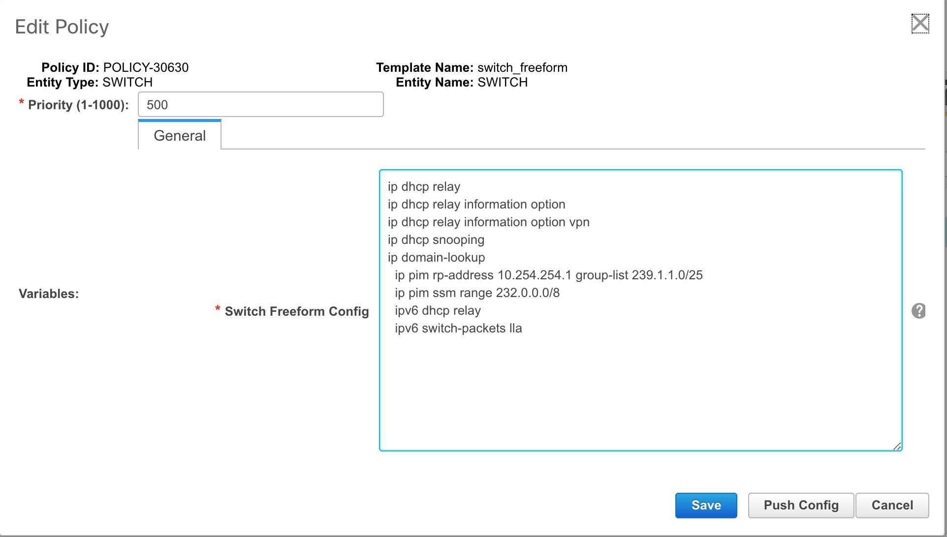
After deploying this policy successfully to the switch, DCNM persistently reports the following diffs:
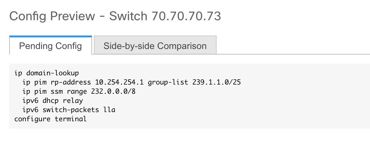
After clicking the Side-by-side Comparison tab, you can see the cause of the diff. As seen below, the ip pim rp-address line has 2 leading spaces, while the running configuration has 0 leading spaces.
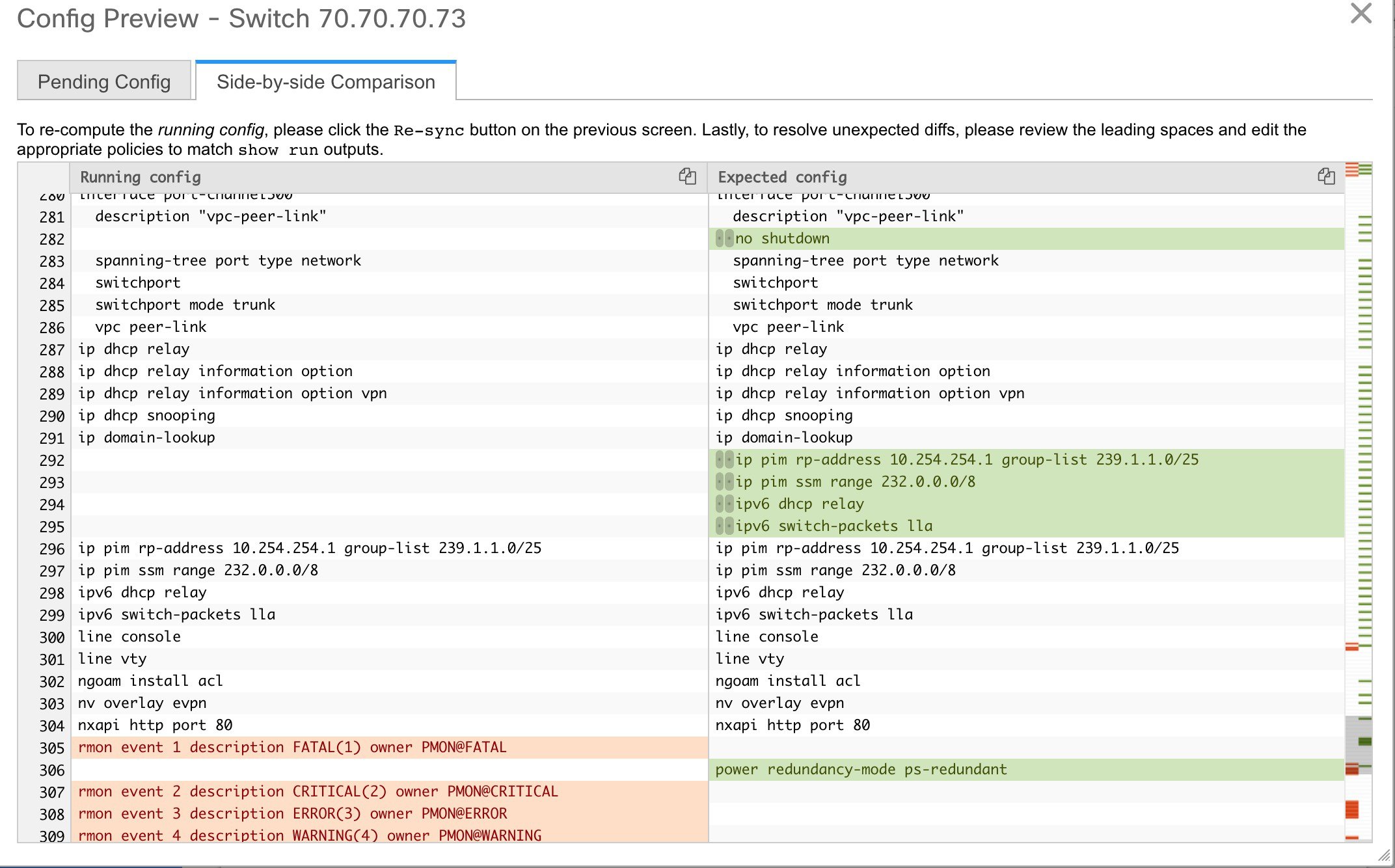
To resolve this diff, edit the corresponding Switch Freeform policy so that the spacing is correct.
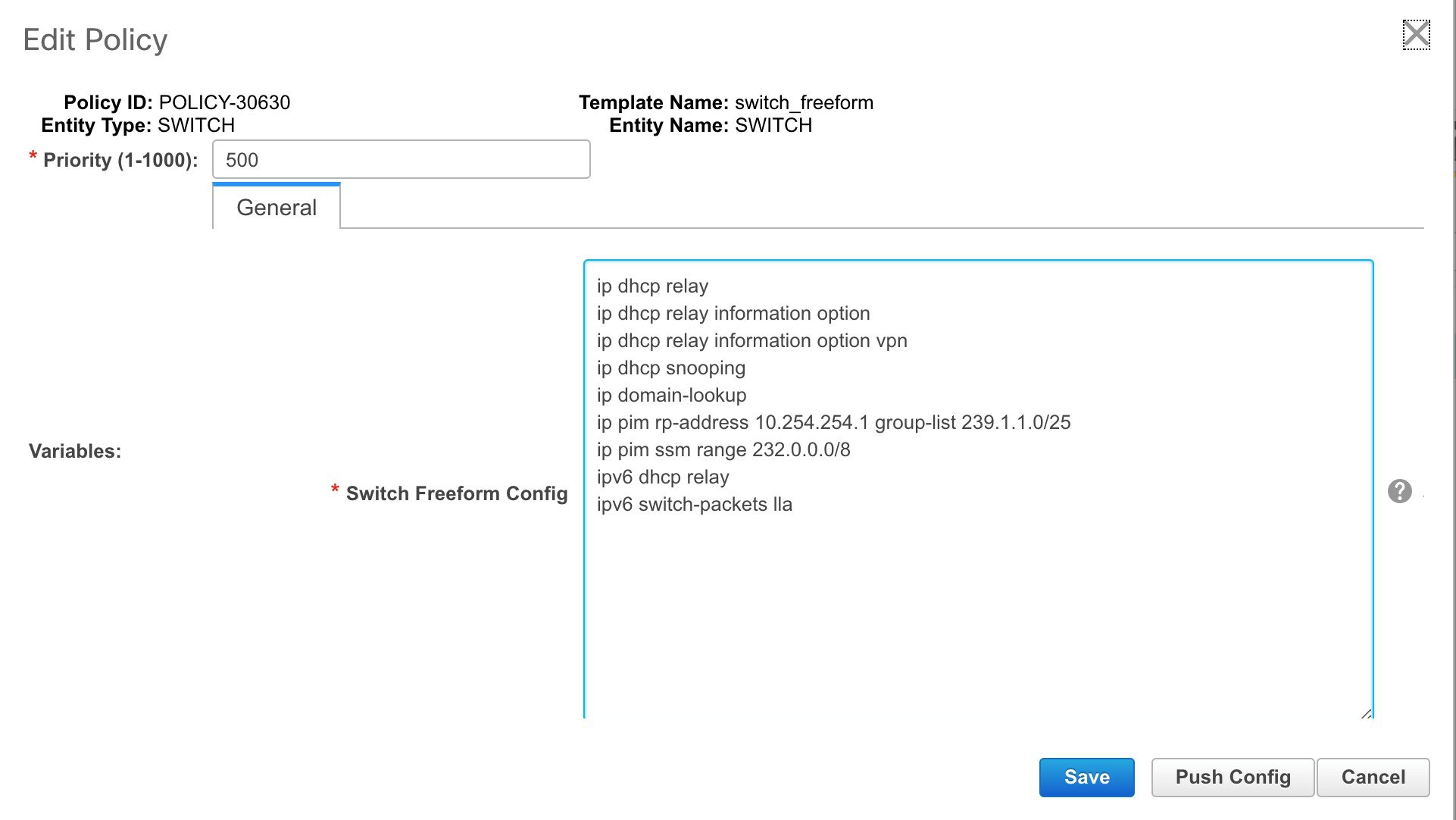
After you save, you can use the Push Config or Save & Deploy option to re-compute diffs.
As shown below, the diffs are now resolved. The Side-by-side Comparison tab confirms that the leading spaces are updated.
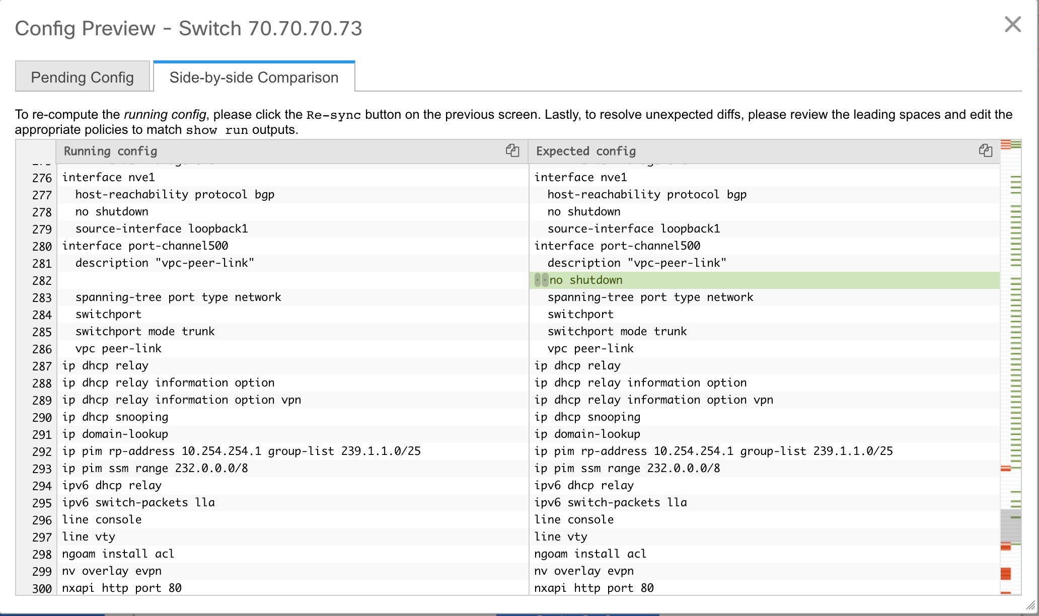
Example 2: Resolving a Leading Space Error in Overlay Configurations
Let us consider an example with a leading space error that is displayed in the Pending Config tab.
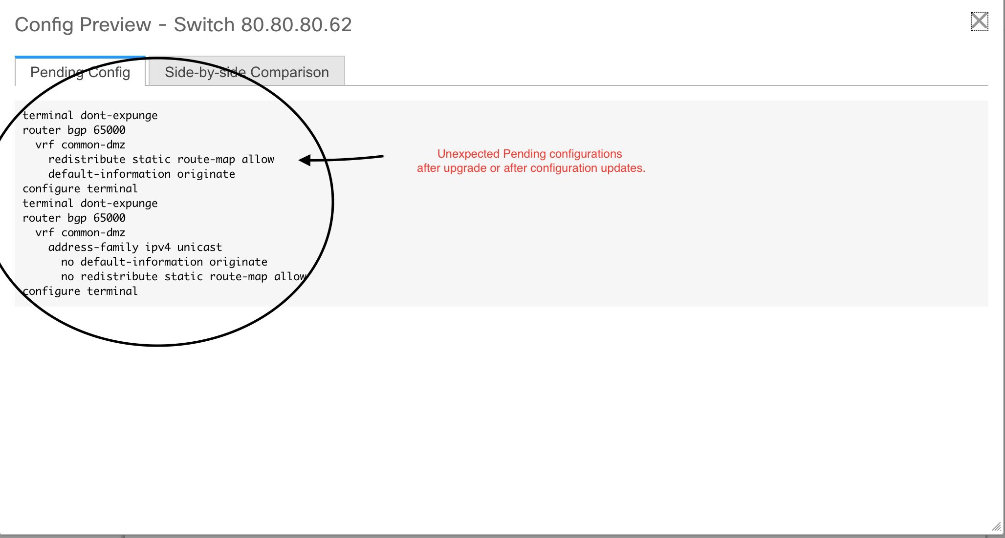
In the Side-by-side Comparison tab, search for diffs line by line to understand context of the deployed configuration.
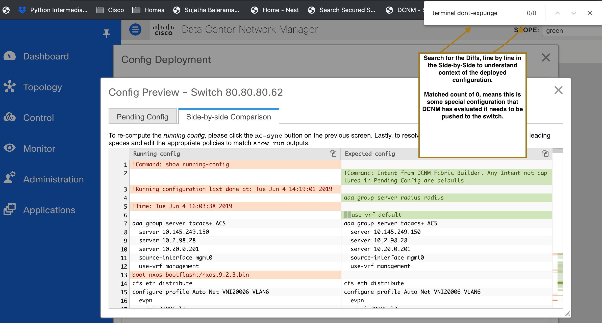
A matched count of 0 means that it is a special configuration that DCNM has evaluated to push it to the switch.
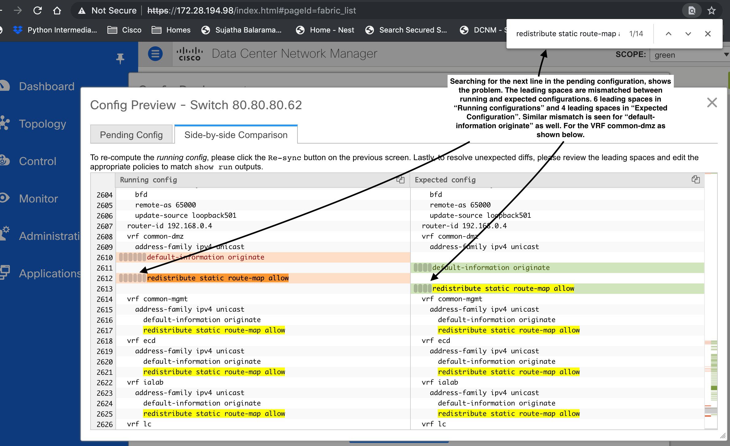
You can see that the leading spaces are mismatched between running and expected configurations.
Navigate to the respective freeform configs and correct the leading spaces, and save the updated configuration.
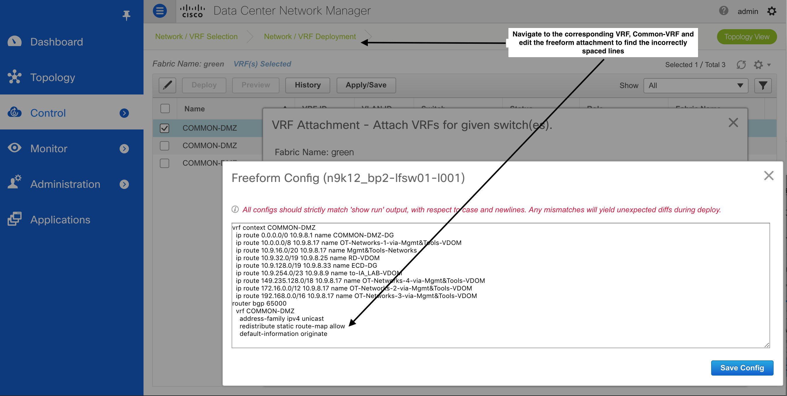
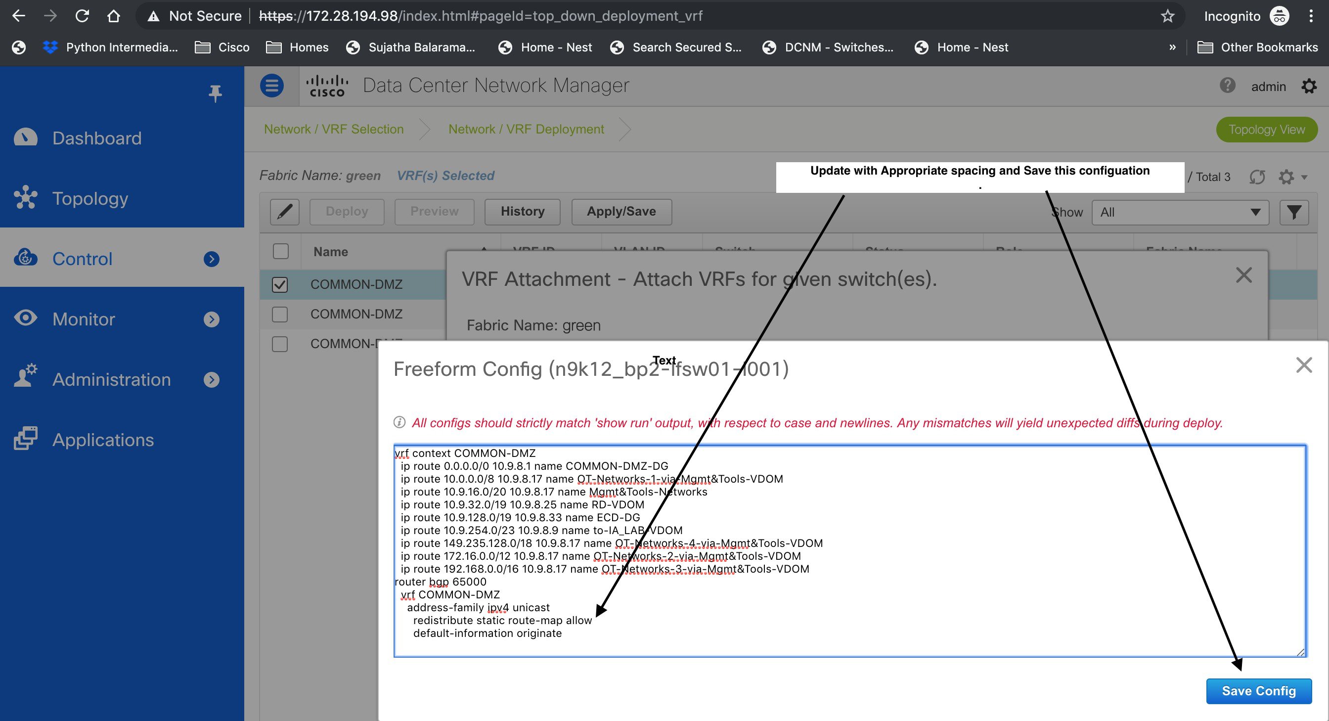
Navigate to the Fabric Builder window for the fabric and click Save & Deploy.
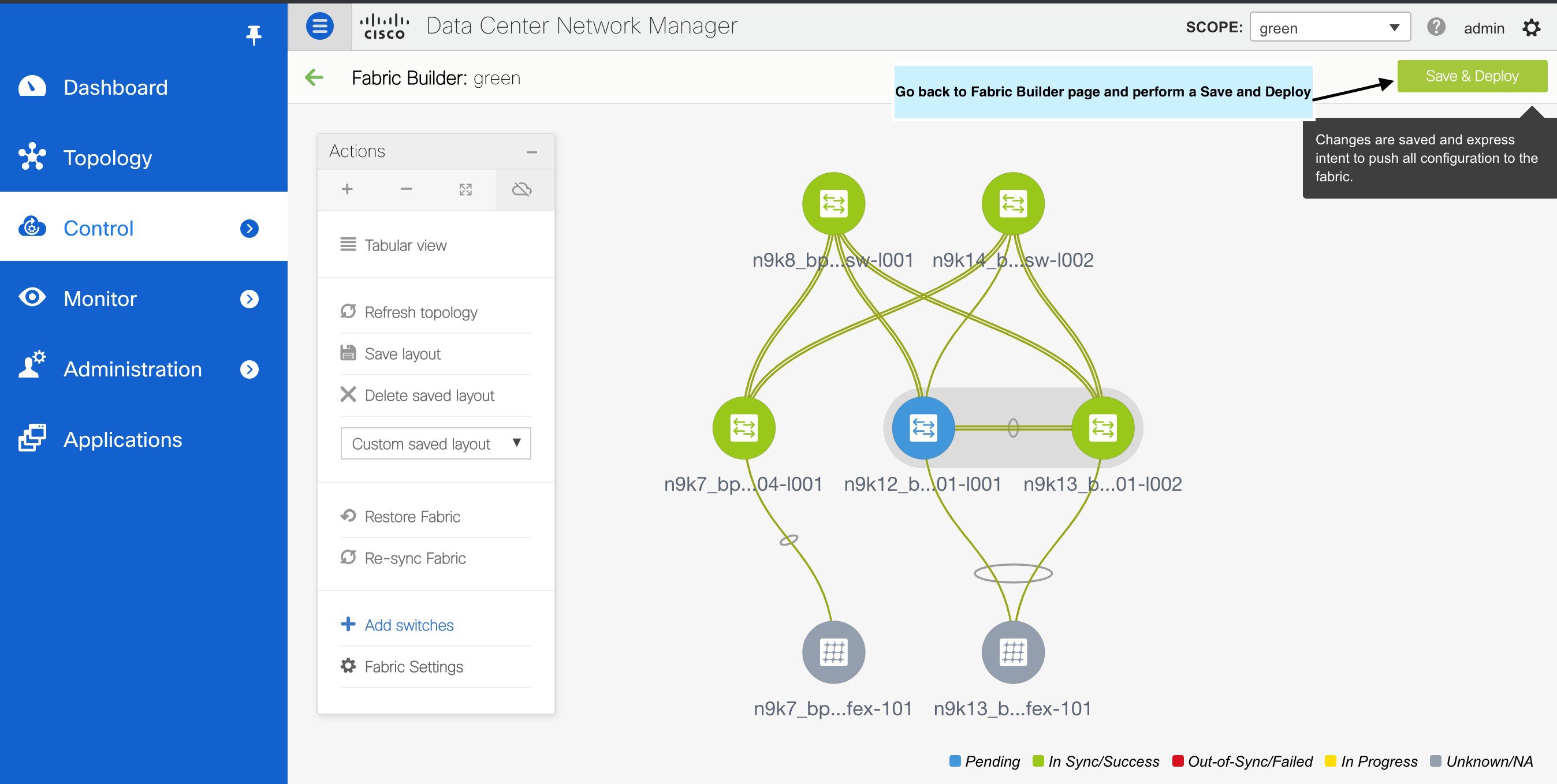
In the Config Deployment window, you can see that all the devices are in-sync.
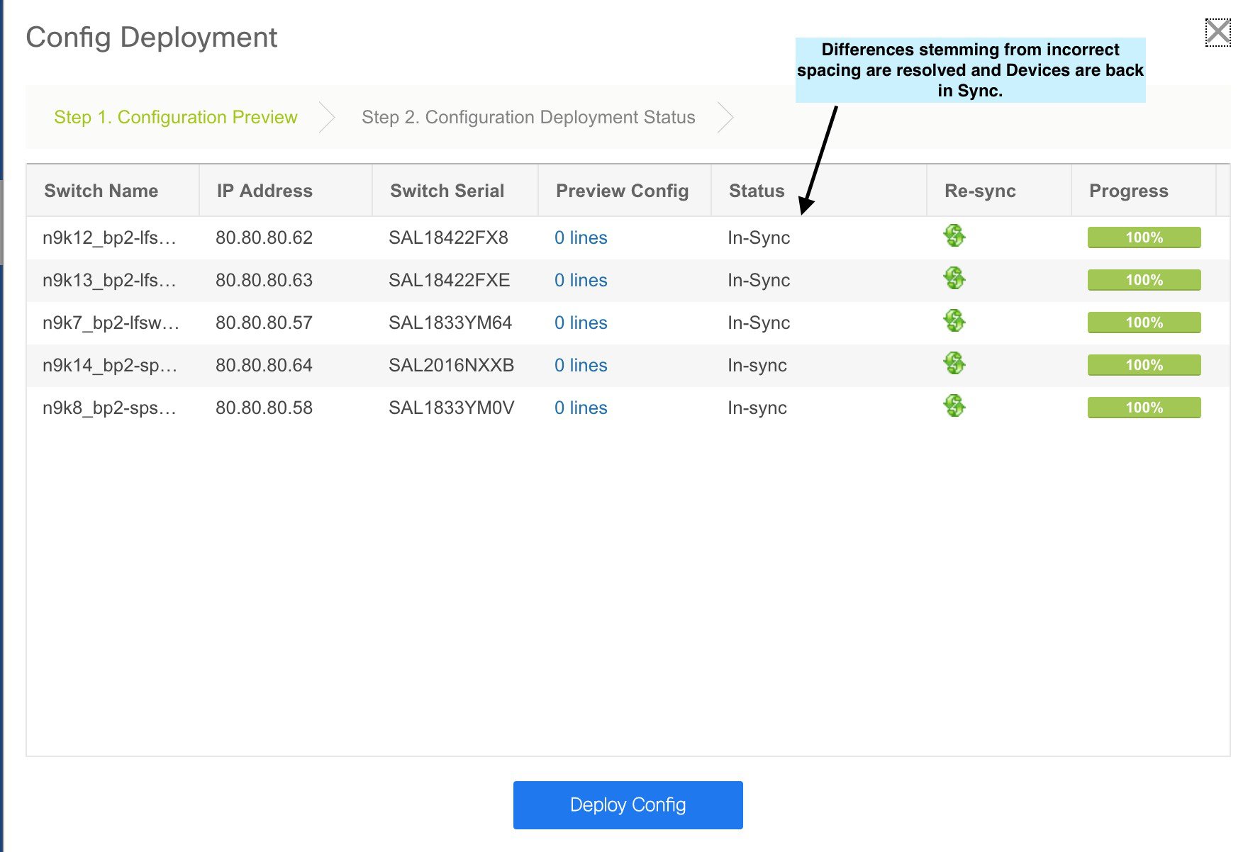
Resolving Diffs for Case Insensitive Commands
By default, all diffs generated in DCNM while comparing intent, also known as Expected Configuration, and Running Configuration, are case sensitive. However, the switch has many commands that are case insensitive, and therefore it may not be appropriate to flag these commands as differences. These outlier cases are captured in the compliance_case_insensitive_clis.txt text file.
There could be additional commands not included in the existing compliance_case_insensitive_clis.txt file that should be treated as case insensitive. If the pending configuration is due to the differences of cases between the Expected Configuration in DCNM and the Running Configuration, you can configure DCNM to ignore these case differences as follows:
-
Modify the following file on the DCNM file system:
/usr/local/cisco/dcm/dcnm/model-config/compliance_case_insensitive_clis.txt
The sample entries in compliance_case_insensitive_clis.txt file are displayed as:
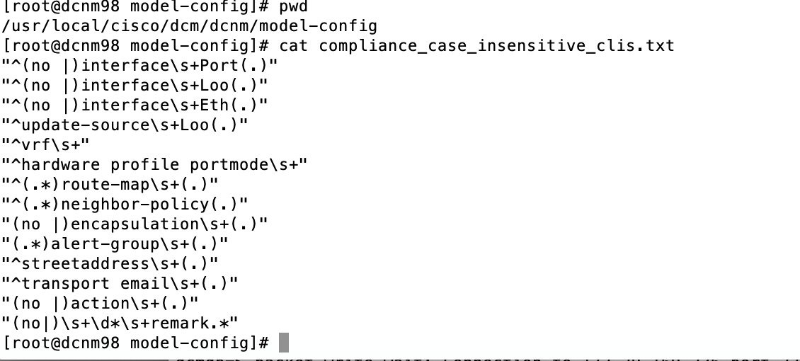
If newer patterns are detected during deployment, and they are triggering pending configurations, you can add these patterns to this file. The patterns need to be valid regex patterns.
This enables DCNM to treat the documented configuration patterns as case insensitive while performing comparisons.
-
Run the following command for each fabric to restart the config compliance container:
# docker exec -it `docker ps | grep compliance | grep <fabric name> | awk '{print $1}'` /usr/bin/pkill python -
Click Save & Deploy for fabrics to see the updated comparison outputs.
Strict Configuration Compliance
From Cisco DCNM Release 11.3(1), strict configuration compliance checks for diff between the switch configuration and the associated intent and generates no commands for the configurations that are present on the switch but are not present in the associated intent. When you click Save and Deploy, switch configurations that are not present on the associated intent are removed. You can enable this feature by selecting the Enable Strict Config Compliance checkbox under the Advanced tab in the Add Fabric or Edit Fabric window. By default, this feature is disabled
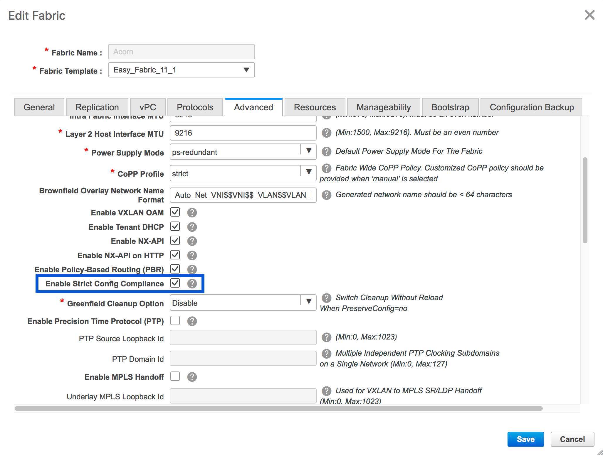
The strict config compliance feature is supported on the Easy Fabric templates - Easy_Fabric_11_1 and Easy_Fabric_eBGP. To avoid generating diff for commands that are auto-generated by the switch, such as vdc, rmon, and so on, a file that has a list of default commands is used by CC to ensure that diffs are not generated for these commands. This file is located at /usr/local/cisco/dcm/dcnm/model-config/strict_cc_exclude_clis.txt.
Note |
In case any diffs are generated after strict configuration compliance is enabled, the switch icon turns blue in color in the Fabric Builder window. |
Example: Strict Configuration Compliance
Let us consider an example in which the feature telnet command is configured on a switch but is not present in the intent. In such a scenario, the status of the switch is displayed as Out-of-sync after a CC check is done.
Now, click Preview Config of the out-of-sync switch. As the strict config compliance feature is enabled, the no form of the feature telnet command appears under Pending Config in the Preview Config window.
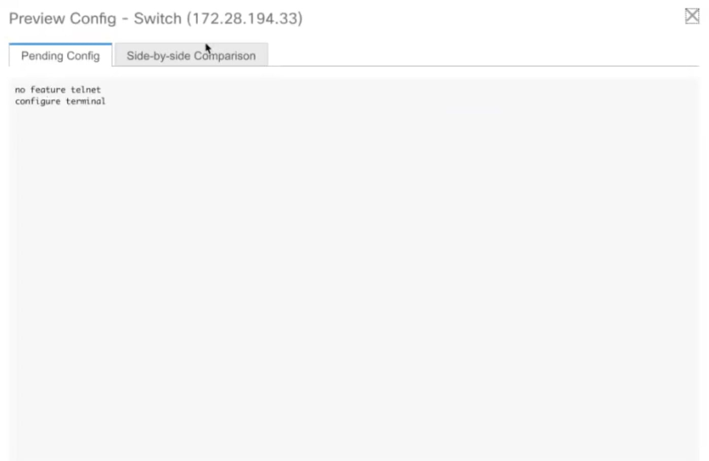
Click the Side-by-side Comparison tab to display the differences between the running configuration and the expected configuration. Starting from Cisco DCNM Release 11.3(1), the Re-sync button is also displayed at the top right corner under the Side-by-side Comparison tab in the Preview Config window. Use this option to resynchronize DCNM state when there is a large scale out-of-band change, or if configuration changes do not register in the DCNM properly.
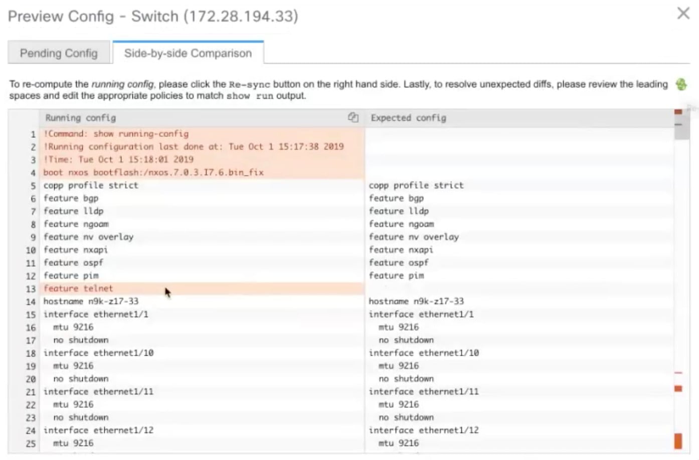
The re-sync operation does a full CC run for the switch and recollects “show run” and “show run all” commands from the switch. When you initiate the re-sync process, a progress message is displayed on the screen. During the re-sync, the running configuration is taken from the switch. The OUT-OF- SYNC/IN-SYNC status for the switch is recalculated based on the intent defined in DCNM.
Now, close the Preview Config window and click Save and Deploy. The Strict configuration compliance feature then ensures that the running config on the switch does not deviate from the intent by pushing the no form of the feature telnet command to the switch. The diff between the configurations is highlighted. The diff other than the feature telnet command are default switch and boot configurations and are ignored by the strict CC check.
In Cisco DCNM Release 11.2(1) and earlier releases, you had to right-click on a switch in the Fabric builder window and select Deploy Config to display the Config Deployment window. You then had to click Preview Config for a specific switch to bring up the Preview Config window that displays the pending configuration for that switch. This leads to a scenario in which the user may think that the preview config is inadvertently being deployed on the switch. Starting from Cisco DCNM Release 11.3(1), you can right-click on a switch in the Fabric Builder window and select Preview Config to display the Preview Config window. This window displays the pending configuration that has to be pushed to the switch to achieve configuration compliance with the intent.
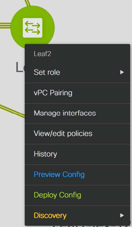
DCNM Tracker
The DCNM Tracker is an application in DCNM targeted for large-scale deployments or for users requiring prompt Out-of-band notifications. From Cisco DCNM Release 11.3(1), the configuration compliance (CC) engine packaged inside DCNM is packaged into a new form factor that can be installed to be present on the switch. The life-cycle management and authentication of the DCNM tracker is managed by DCNM. Installation of a DCNM tracker leads to the installation of a small utility that runs on the guestshell of the switch and monitors changes in intent, running configuration, and so on. The changes are then relayed back to the parent DCNM instance. Scaling out the configuration compliance engine in this way ensures that largescale deployments are not cadence bound by a single compliance engine present in DCNM.
In earlier Cisco DCNM releases, by default, a periodic configuration compliance check occurred every 60 minutes. From Cisco DCNM Release 11.3(1), use the DCNM tracker feature to enable continuous configuration compliance (CC) checks. In case the strict configuration compliance feature has also been enabled, the DCNM tracker enables continuous strict CC checks. The DCNM tracker runs a localized CC check that occurs on the switch. Configuration compliance leverages information from the DCNM tracker for configuration compliance checks for switches on which the tracker has been enabled and uses the regular configuration compliance checks for switches on which the DCNM tracker has not been installed. We recommend using the DCNM tracker for large-scale deployments and for scenarios in which prompt OOB configuration changes. By default, the DCNM tracker is not installed. The DCNM tracker is supported on Cisco Nexus 3000 Series and Cisco Nexus 9000 Series switches.
Installing the DCNM Tracker
Procedure
| Step 1 |
Choose Control > Fabric Builder. The Fabric Builder window comes up. A rectangular box represents each fabric. Select a fabric. |
| Step 2 |
Click Tabular View in the Actions window. 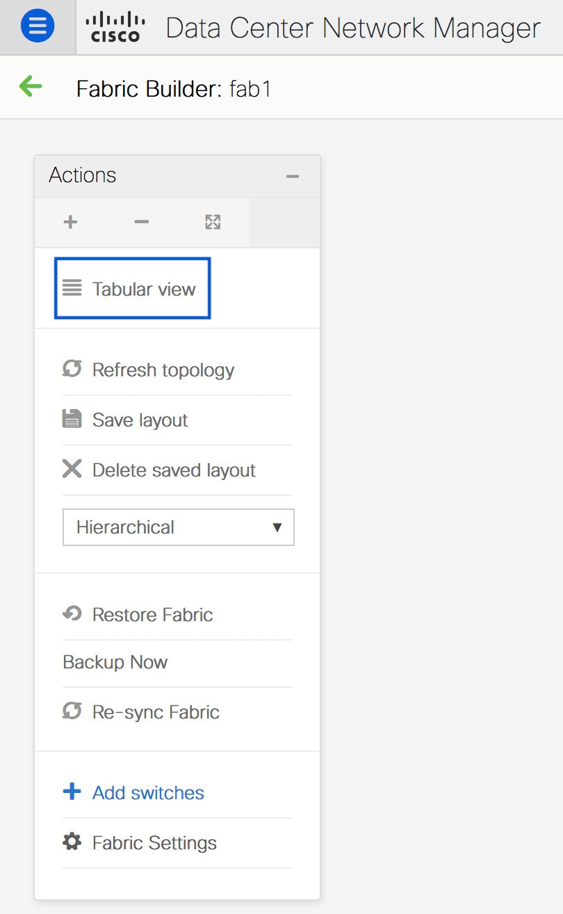 |
| Step 3 |
Select the switches on which the DCNM tracker has to be enabled and click Tracker Actions. 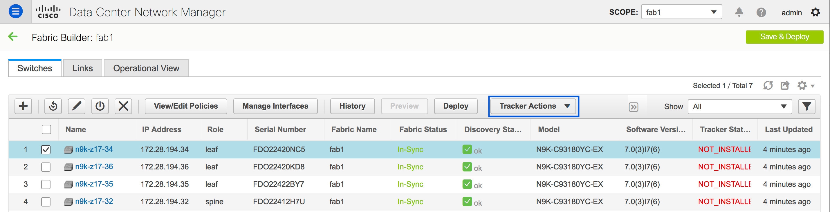 There are four options under Tracker Actions:
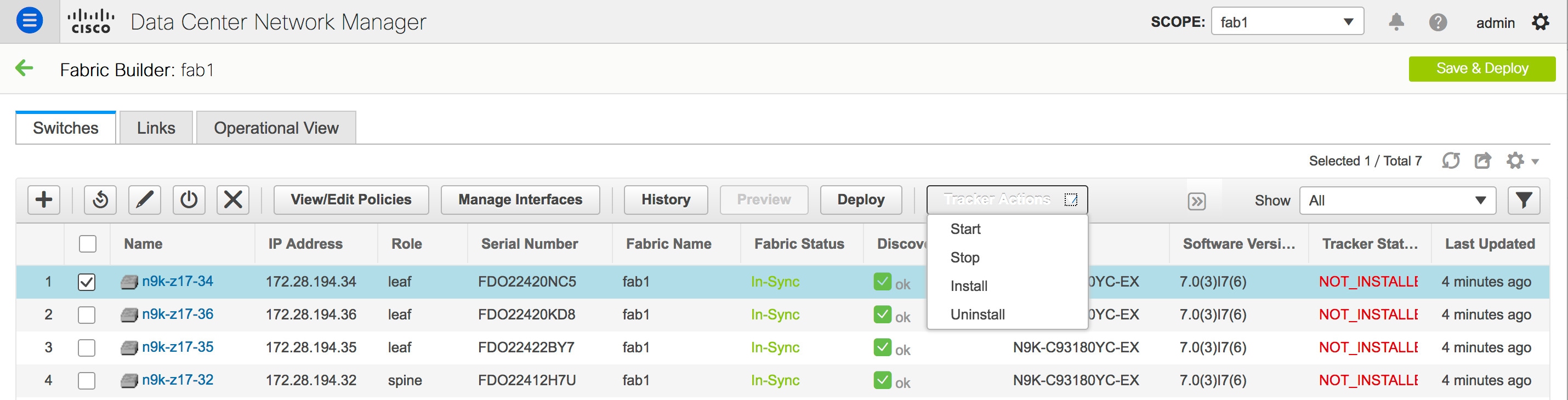 |
| Step 4 |
Click Install under Tracker Actions. 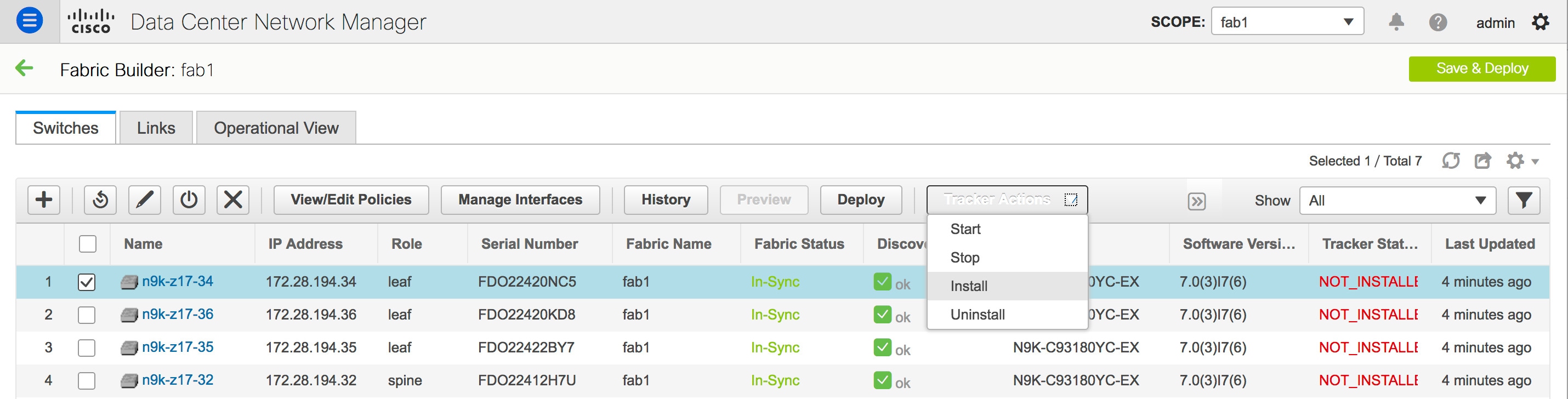 Installation of the DCNM tracker is then initiated. The DCNM tracker installation process may take up to a few minutes. A pop-up window appears after the installation has been completed stating DCNM Tracker actions completed. Please check status!. The Tracker Status comes up as RUNNING for the switch on which the DCNM tracker has been installed. In case of an error, hover over the status message under Tracker Status to view the root cause of the error. |
Uninstalling the DCNM Tracker
Click Uninstall under Tracker Actions.
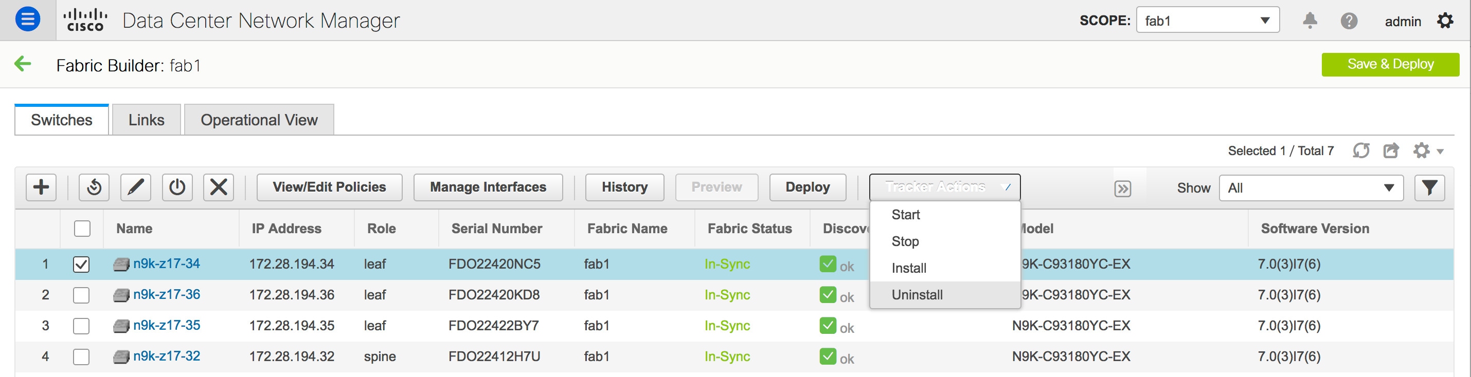
Starting the DCNM Tracker
To start the DCNM tracker on a switch on which the tracker has already been installed, click Start under Tracker Actions.
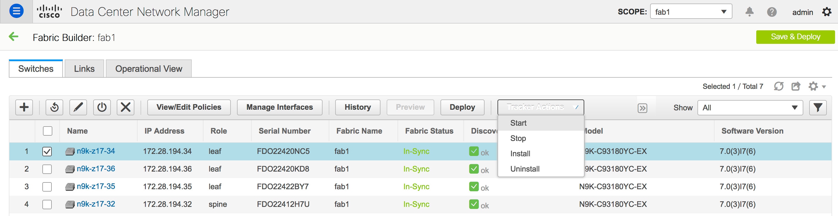
Stopping the DCNM Tracker
To stop the DCNM tracker on a switch without uninstalling the tracker, click Stop under Tracker Actions.
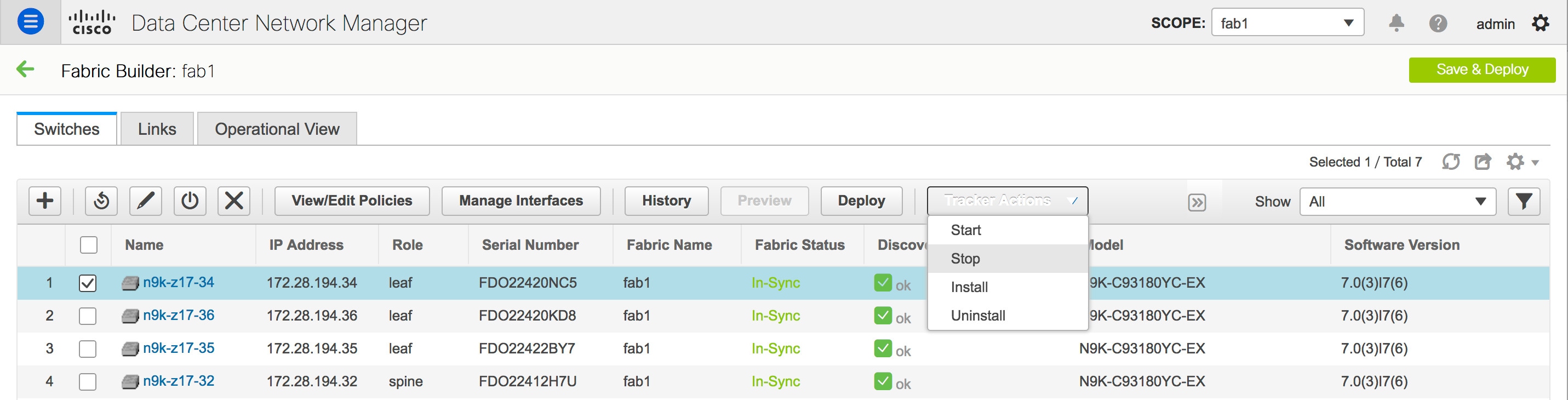
DCNM Tracker Status
The status of the DCNM tracker is displayed in the Tracker Status column under the Switches tab in the Fabric Builder window. The status messages are as listed below:
-
INSTALLED - The DCNM tracker has been installed on the switch.
-
NOT_INSTALLED - The DCNM tracker has not been installed on the switch.
-
INSTALLEDOTHER - The DCNM tracker is installed on the switch but is associated with a different DCNM instance. In such a scenario, uninstall the tracker and then re-install it. The tracker will then be associated with the current DCNM instance. Hover over the tracker status to view the IP address of the DCNM that the tracker is associated with.
-
DISCOVERING - The DCNM tracker status is being discovered. In case the tracker is in this state for more than a few minutes, select the switch and initiate a rediscovery to force a manual rediscovery of the DCNM tracker status.
-
RUNNING - The DCNM tracker is active on the switch.
-
STOPPED - The DCNM tracker has been stopped on the switch.
-
ERROR - Indicates that an error has occurred during the tracker install/uninstall/start/stop process. Hover over the tracker status for more information on the cause of the error.
-
UNSUPPORTED_PLATFORM - The DCNM tracker is not supported on this switch.
When a switch is in Unreachable discovery status, the last available tracker status of the switch is retained. For example, if the switch was in RUNNING tracker status before it becomes unreachable, the value under the Tracker Status column for this switch will still be RUNNING despite the switch being in Unreachable discovery status.
Hover over the tracker status message for more information.
Refer Configuration Compliance in DCNM for more information.
Troubleshooting - DCNM Tracker
To troubleshoot a DCNM installation in which the DCNM tracker is installed on switches, go to https://DCNM-IP/api-docs/#/Control_-_DCNM_Tracker/backup, and execute the backup REST API option under DCNMTracker.
Backup - DCNM Tracker
Go to https://DCNM-IP/api-docs/#/Control_-_DCNM_Tracker/backupTracker to back up all the tracker log files from all installed switches and save them in the DCNM instance under the /usr/local/cisco/dcm/fm/logs/dcnmtracker directory. Using the appmgr backup command will then result in collection of all the logs in this directory.
Enabling Freeform Configurations on Fabric Switches
In DCNM, you can add custom configurations through freeform policies in the following ways:
-
Fabric-wide
-
On all leaf and border leaf switches in the fabric, at once.
-
On all spine and border spine switches, at once.
-
-
On a specific switch.
Leaf switches are identified by the roles Leaf, Border and Border Gateway and spine switches by the roles Spine, Border Spine, and Border Gateway Spine.
Note |
You can deploy freeform CLIs when you create a fabric or when a fabric is already created. The following examples are for an existing fabric. However, you can use this as a reference for a new fabric. |
Deploying Fabric-Wide Freeform CLIs on Leaf and Spine Switches
-
Click Control > Fabric Builder. The Fabric Builder screen comes up. A rectangular box represents each fabric.
-
Click the Edit Fabric icon (located on the top right part of the rectangular box) for adding custom configurations to an existing fabric. The Edit Fabric screen comes up.
(If you are creating a fabric for the first time, click Create Fabric).
-
Click the Advanced tab and update the following fields:
Leaf Freeform Config – In this field, add configurations for all leaf and border leaf switches in the fabric.
Spine Freeform Config - In this field, add configurations for all Spine, Border Spine, and Border Gateway Spine switches in the fabric.
Note
Copy-paste the intended configuration with correct indentation, as seen in the running configuration on the Nexus switches. For more information, see Resolving Freeform Config Errors in Switches.
-
Click Save. The fabric topology screen comes up.
-
Click Save & Deploy at the top right part of the screen to save and deploy configurations.
Configuration Compliance functionality will ensure that the intended configuration as expressed by those CLIs are present on the switches and if they are removed or there is a mismatch, then it will flag it as a mismatch and indicate that the device is OUT-OF-SYNC.
Incomplete Configuration Compliance - On some Cisco Nexus 9000 Series switches, in spite of configuring pending switch configurations using the Save & Deploy option, there could be a mismatch between the intended and switch configuration. To resolve the issue, add a switch_freeform policy to the affected switch (as explained in the Deploy Freeform CLIs on a Specific Switch section). For example, consider the following persistent pending configurations:
line vty
logout-warning 0
After adding the above configurations in a policy and saving the updates, click Save and Deploy in the topology screen to complete the deployment process.
To bring the switch back in-sync, you can add the above configuration in a switch_freeform policy saved and deployed onto the switch.
Deploying Freeform CLIs on a Specific Switch
-
Click Control > Fabric Builder. The Fabric Builder screen comes up.
-
Click on the rectangular box that represents the fabric. The Fabric Topology screen comes up.
Note
To provision freeform CLIs on a new fabric, you have to create a fabric, import switches into it, and then deploy freeform CLIs.
-
Right-click the switch icon and select the View/edit policies option.
The View/Edit Policies screen comes up.
-
Click +. The Add Policy screen comes up.
In the Priority field, the priority is set to 500 by default. You can choose a higher priority (by specifying a lower number) for CLIs that need to appear higher up during deployment. For example, a command to enable a feature should appear earlier in the list of commands.
-
From the Policy field, select switch_freeform.
-
Add or update the CLIs in the Freeform Config CLI box.
Copy-paste the intended configuration with correct indentation, as seen in the running configuration on the Nexus switches. For more information, see Resolving Freeform Config Errors in Switches.
-
Click Save.
After the policy is saved, it gets added to the intended configurations for that switch.
-
Close the policy screens. The Fabric Topology screen comes up again.
-
Right click the switch and click Deploy Config.
The Save & Deploy option can also be used for deployment. However, the Save & Deploy option will identify mismatch between the intended and running configuration across all fabric switches.
Pointers for switch_freeform Policy Configuration:
-
You can create multiple instances of the policy.
-
For a vPC switch pair, create consistent switch_freeform policies on both the vPC switches.
-
When you edit a switch_freeform policy and deploy it onto the switch, you can see the changes being made (in the Side-by-side tab of the Preview option).
Freeform CLI Configuration Examples
Console line configuration
This example involves deploying some fabric-wide freeform configurations (for all leaf, and spine switches), and individual switch configurations.
Fabric-wide session timeout configuration:
line console
  exec-timeout 1
Console speed configuration on a specific switch:
line console
  speed 115200
ACL configuration
ACL configurations are typically configured on specific switches and not fabric-wide (leaf/spine switches). When you configure ACLs as freeform CLIs on a switch, you should include sequence numbers. Else, there will be a mismatch between the intended and running configuration. A configuration sample with sequence numbers:
ip access-list ACL_VTY
  10 deny tcp 172.29.171.67/32 172.29.171.36/32
  20 permit ip any any
ip access-list vlan65-acl
  10 permit ip 69.1.1.201/32 65.1.1.11/32
  20 deny ip any any

interface Vlan65
  ip access-group vlan65-acl in
line vty
  access-class ACL_VTY in
If you have configured ACLs without sequence numbers in a switch_freeform policy, update the policy with sequence numbers as shown in the running configuration of the switch.
After the policy is updated and saved, right click the device and select the per switch Deploy Config option to deploy the configuration. Alternatively, use the Save and Deploy option in the fabric topology screen (within Fabric Builder) so that the fabric triggers Configuration Compliance and resolves the configuration mismatch.
Resolving Freeform Config Errors in Switches
Copy-paste the running-config to the freeform config with correct indentation, as seen in the running configuration on the NX-OS switches. The freeform config must match the running config. Otherwise, configuration compliance in DCNM marks switches as out-of-sync.
Let us see an example of the freeform config of a switch.
feature bash-shell
feature telemetry

clock timezone CET 1 0
# Daylight saving time is observed in Metropolitan France from the last Sunday in March (02:00 CET) to the last Sunday in October (03:00 CEST)
clock summer-time CEST 5 Sunday March 02:00 5 Sunday October 03:00 60
clock protocol ntp

telemetry
  destination-profile
    use-vrf management
The highlighted line about the daylight saving time is a comment that is not displayed in the show running config command output. Therefore, configuration compliance marks the switch as out-of-sync because the intent does not match the running configuration.
Let us check the running config in the switch for the clock protocol.
spine1# show run all | grep "clock protocol"
clock protocol ntp vdc 1
You can see that vdc 1 is missing from the freeform config.
In this example, let us copy-paste the running config to the freeform config.
Here is the updated freeform config:
feature bash-shell
feature telemetry

clock timezone CET 1 0
clock summer-time CEST 5 Sunday March 02:00 5 Sunday October 03:00 60
clock protocol ntp vdc 1

telemetry
  destination-profile
    use-vrf management
After you copy-paste the running config and deploy, the switch will be in-sync. When you click Save & Deploy, the Side-by-side Comparison tab in the Config Preview window provides you information about the difference between the defined intent and the running config.
Layer 4-Layer 7 Service
Cisco DCNM Release 11.3(1) introduces the ability to insert Layer 4-Layer 7 (L4-L7) service devices in a data center fabric, and also enables selectively redirecting traffic to these service devices. You can add a service node, create route peering between the service node and the service leaf switch, and then selectively redirect traffic to these service nodes.
Service Node
You have to create an external fabric and specify that a service node resides in that external fabric during service node creation. DCNM does not auto-detect or discover any service node. You also have to specify the service node name, type, and form factor. The name of the service node has to be unique within a fabric. The service node is attached to a leaf, border leaf, border spine, or a border super spine switch. DCNM does not define a new switch role for a service leaf.
DCNM manages the switches that are attached to a service node. DCNM also manages the interfaces of these attached switches. Ensure that the interfaces to which the service node is attached to are in trunk mode. The L4-L7 service will not change its mode. In case the attached switches are forming a vPC pair, the name of the attached switch is a combination of both switches.
Route Peering
Route peering creates service networks. DCNM supports both static route and eBGP-based dynamic route peering options. After you specify the service network and select the peering policy for the tenant, DCNM automatically creates the service network under the specified tenant. Note that the terms, tenant and VRF, will be used interchangeably in this guide. If you select a route peering and click Deploy in the Service Nodes window, the L4-L7 service deploys the corresponding service network and VRF configuration to the leaf that is attached to the service node. Click Preview to review both the peering and service network configuration.
The automatically created service network will also be listed on the Control > Fabrics > Networks window. You can view and edit the corresponding config parameters in the Networks window. However, you cannot delete the service network. Deletion of service networks is handled automatically during the service route peering deletion process. There can be multiple route peerings defined per tenant/VRF.
Service Policy
You can only define the service policy between the created networks. The L4-L7 service does not create any VRF or network other than the service networks that are defined during route peering. The source and destination network can be a subnet, an individual IP address or the networks that are defined in the Control > Fabrics > Networks window. Note that the source or destination network can also be defined by using the any CLI keyword. This means that any IP address traffic is supported. For intra-tenant firewall, one-arm and two-arm load balancer, the L4-L7 service in DCNM uses Policy-Based Routing (PBR) for service insertion. The inter-tenant firewall does not have a service policy. You only need to create a service node and route peering for inter-tenant firewall.
As the source and destination network can be attached or deployed independent of service policy deployment, the tenant/ VRF-related service policy configuration is only attached or pushed to the switch that is attached to the service node, and the source and destination network is updated with the service policy-related configuration. You can preview and confirm the generated configuration. By default, the service policy is defined but is not enabled or attached. You have to enable or attach the service policy to activate it.
The service configuration that is related to the source and destination network will be auto-processed when the source and destination networks are to be attached, or auto-updated in case the networks are already attached or deployed. By default, DCNM will collect statistics every 5 minutes and store it in ElasticSearch for aggregation and analysis. Click the graph line under Stats in the Service Policy tab of the Service Nodes window to view the historical time-based statistics. By default, the statistics are stored for a maximum of 7 days.
The service insertion is effective only on the flows to be created. There is no impact on any existing flows. Deletion of a network is not allowed in case an enabled service policy is associated with that network.
The L4-L7 service integration is built on top of the easy fabric policy enforcement. Use the fabric builder to create a VXLAN EVPN fabric and then import Cisco Nexus 9000 Series switches into the fabric with pre-defined fabric policies.
Guidelines and Limitations for Layer 4-Layer 7 Service
-
L4-L7 service in DCNM does not manage or provision service nodes, such as firewall and load balancer.
-
This feature is supported only on VXLAN BGP EVPN fabrics.
-
The service policies defined in this feature leverage Policy-Based Routing (PBR). Refer Nexus 9000 Series NX-OS Unicast Routing Configuration Guide for PBR related configuration, constraints, and so on.
-
This feature supports Cisco Nexus 9300-EX and 9300-FX platform switches as leaf, border leaf, border spine, or border super spine switches.
-
Configurations involving intra-tenant and inter-tenant firewall for L3 networks, and one-arm and two-arm deployed load balancers, are supported.
-
The existing DCNM topology view is also leveraged to display redirected flows associated with the switches that the service node is attached to, and to locate specific redirected flows.
-
Load sharing is not supported.
-
This feature does not support Multi-Site Domains (MSD).
-
This feature creates, updates, and deletes the service network, as required. Service networks cannot be created or deleted from the Control > Fabrics > Networks window.
Configuring Fabric Settings for Layer 4-Layer 7 Service
Certain fabric settings have to be configured to enable L4-L7 service functionality. To configure these settings, click Fabric Settings under Actions in the Fabric Builder window.
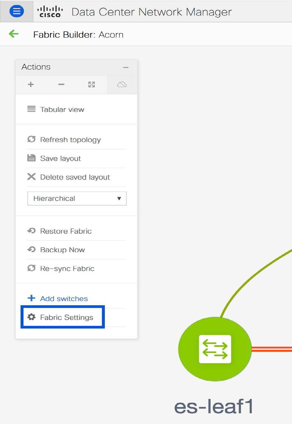
The Edit Fabric window is displayed. Click Advanced. Select the Enable Policy-Based Routing (PBR) checkbox to enable routing of packets based on the specified policy.
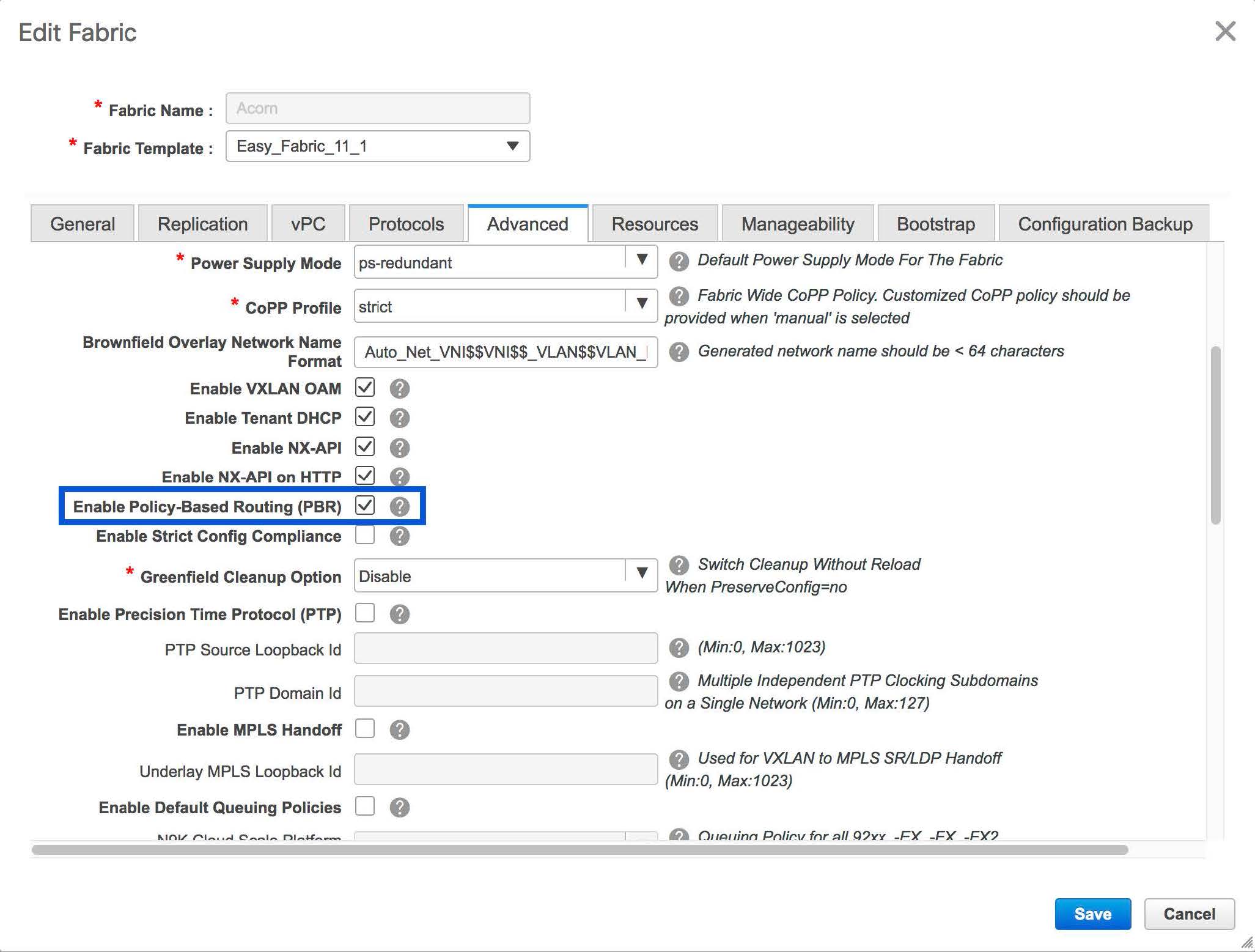
Now, click Resources. Specify a VLAN range in the Service Network VLAN Range field. This is a per switch overlay service network VLAN range. The minimum allowed value is 2 and the maximum allowed value is 3967. Also, specify a value for the Route Map Sequence Number Range field. The minimum allowed value is 1 and the maximum allowed value is 65534. Click Save and Deploy to deploy the updated configuration.
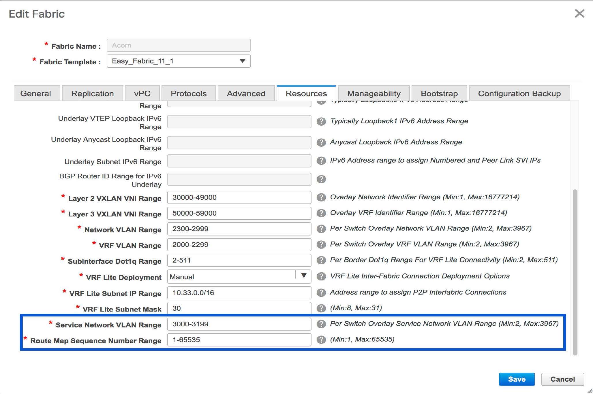
Configuring Layer 4-Layer 7 Service
To launch the L4-L7 Service, or the Elastic Service, on the Cisco DCNM Web UI, choose Control>Fabrics>Services.
The Service Nodes window is displayed. Select a valid switch fabric to display or define the service nodes, route peerings, and service policies, in that fabric.
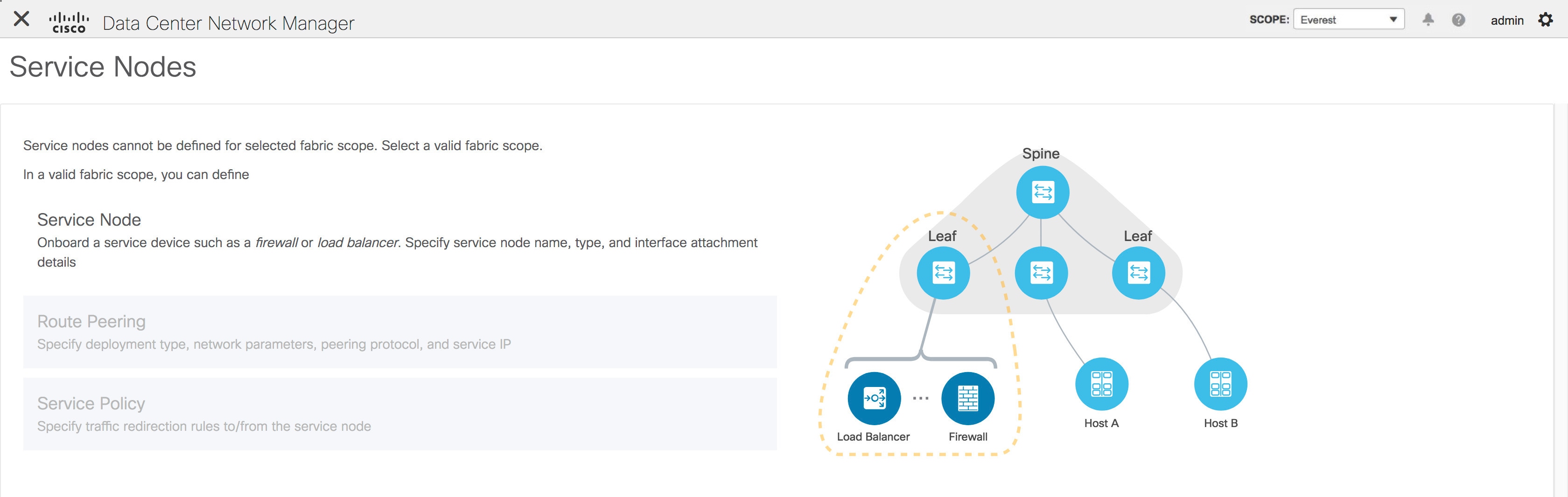
The L4-L7 service configuration procedure consists of the following steps:
Create Service Node
To create a service node, click the + icon at the top right of the Service Nodes window to display the New Service Nodes window.
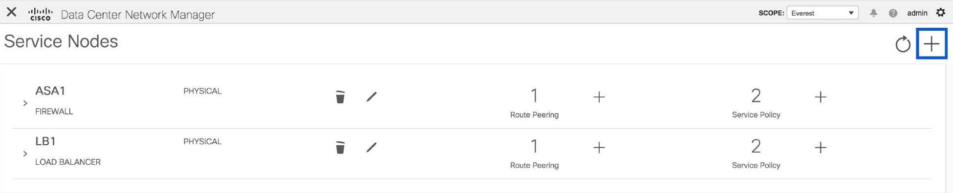
The New Service Nodes window has three steps, Create Service Node, Create Route Peering and Create Service Policy.
The Create Service Node window has two sections - Create Service Node and Switch Attachment, followed by a Link Template drop-down list. You can select service_link_trunk, service_link_port_channel_trunk and service_link_vpc from this drop-down list..
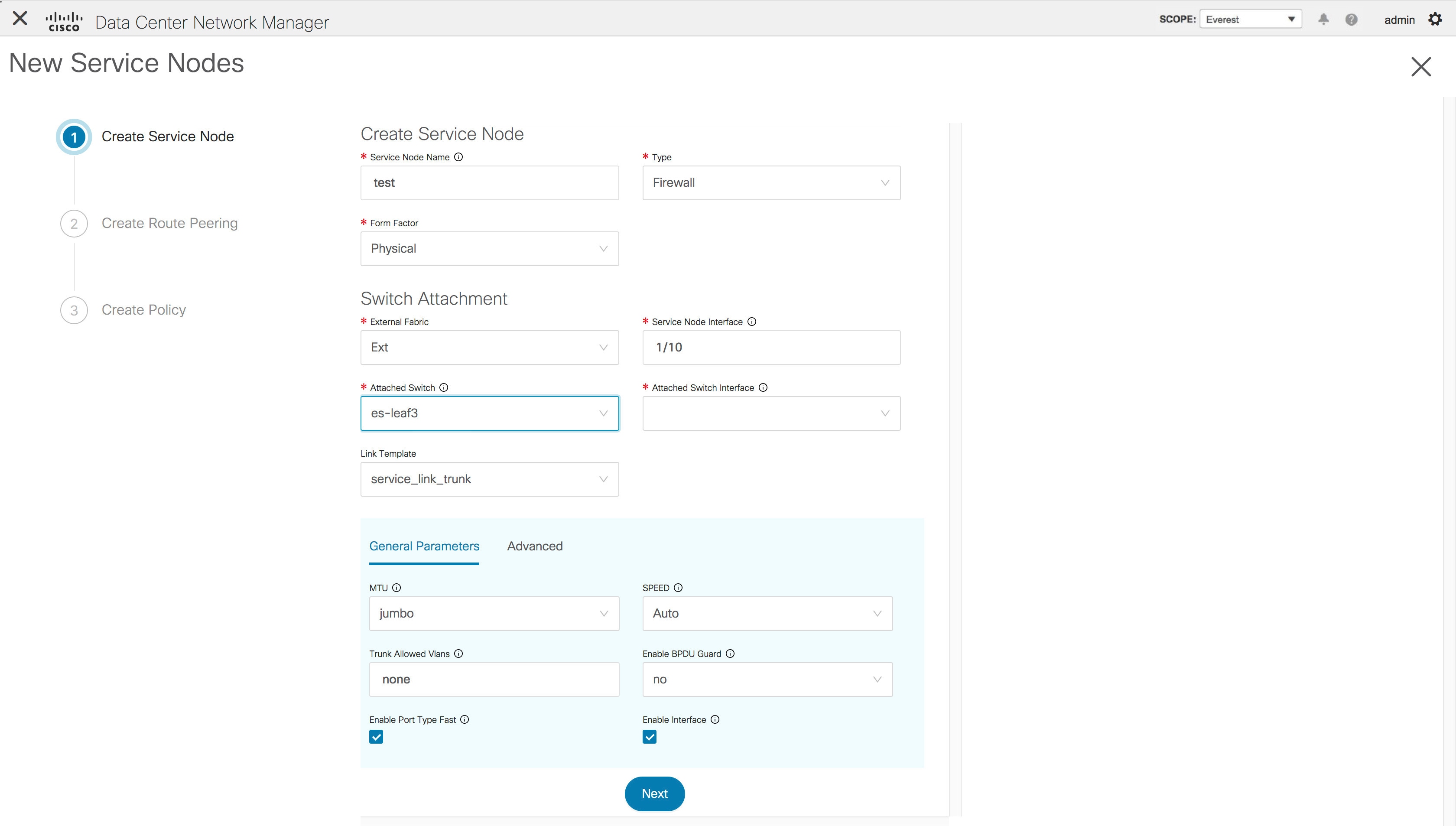
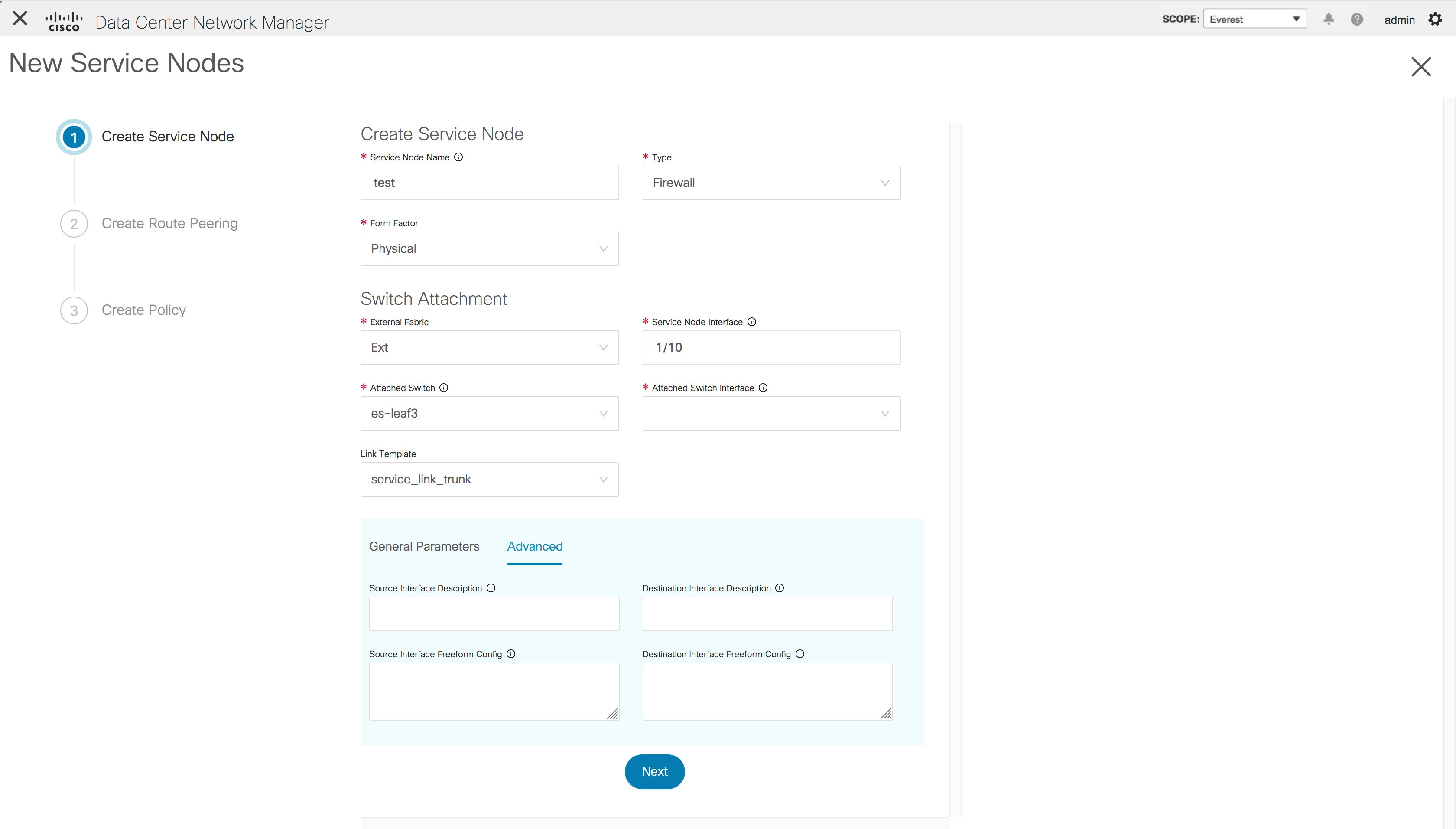
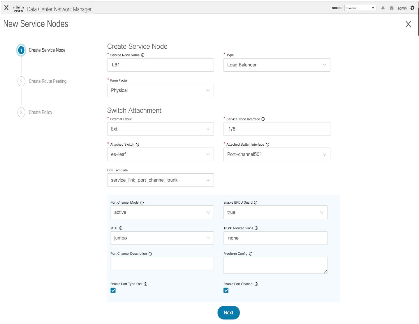
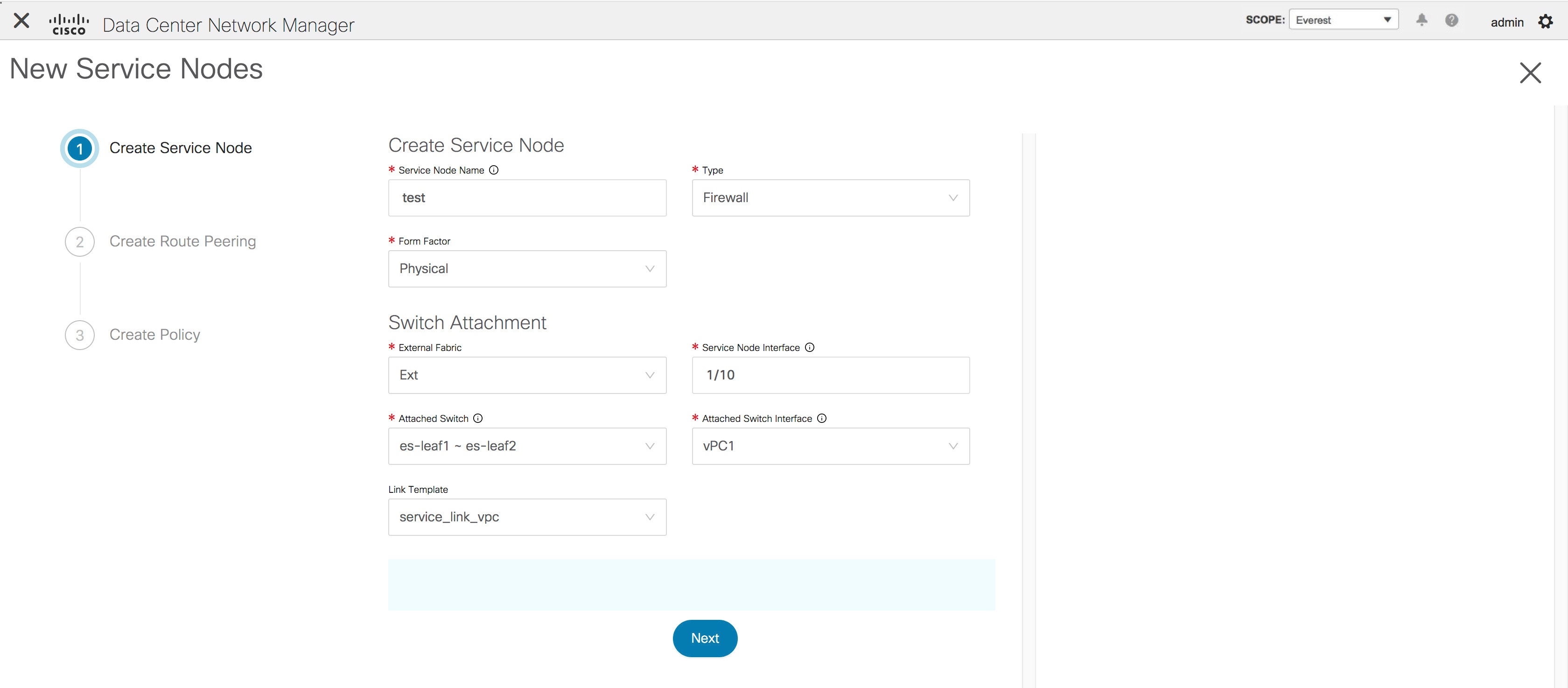
The fields in the Create Service Node window are as given below. It is mandatory to fill the fields marked with an asterisk. For more information on the fields in this window, hover over the i icon.
Create Service Node
Service Node Name - Enter a name for the service node. The name can have alphanumeric, underscore, or dash characters.
Type - Select Firewall or Load Balancer.
Form Factor - Select Physical or Virtual.
Switch Attachment
External Fabric - Specify the external fabric.
Service Node Interface - Specify the service node interface.
Attached Switch- Select a switch from the drop-down list.
Attached Switch Interface - Select the interface from the drop-down list. In case the vPC pair is selected from the Attached Leaf Switch drop-down list, the vPC channel will be shown in the Attached Leaf Switch Interface drop-down list. Otherwise, the port-channel and interfaces with trunk mode are shown in the Attached Leaf Switch Interface drop-down list.
Link Template - Select the service_link_trunk, service_link_port_channel_trunk, or the service_link_vpc template. For more information on template fields, refer Templates.
Now, click Next. A pop-up window is displayed stating that a new service node has been created successfully and the Create Route Peering window is displayed.
Create Route Peering
The fields that appear in the Create Route Peering window depend on the type of deployment chosen in the Create Service Node window. Depending on the type chosen (Firewall or Load Balancer), the types of deployments are Intra-Tenant Firewall, Inter-Tenant Firewall, One-Arm load balancer and Two-Arm load balancer.
Note |
Deletion of service network is not supported in Top-down provisioning. |
Example: Intra-Tenant Firewall Deployment
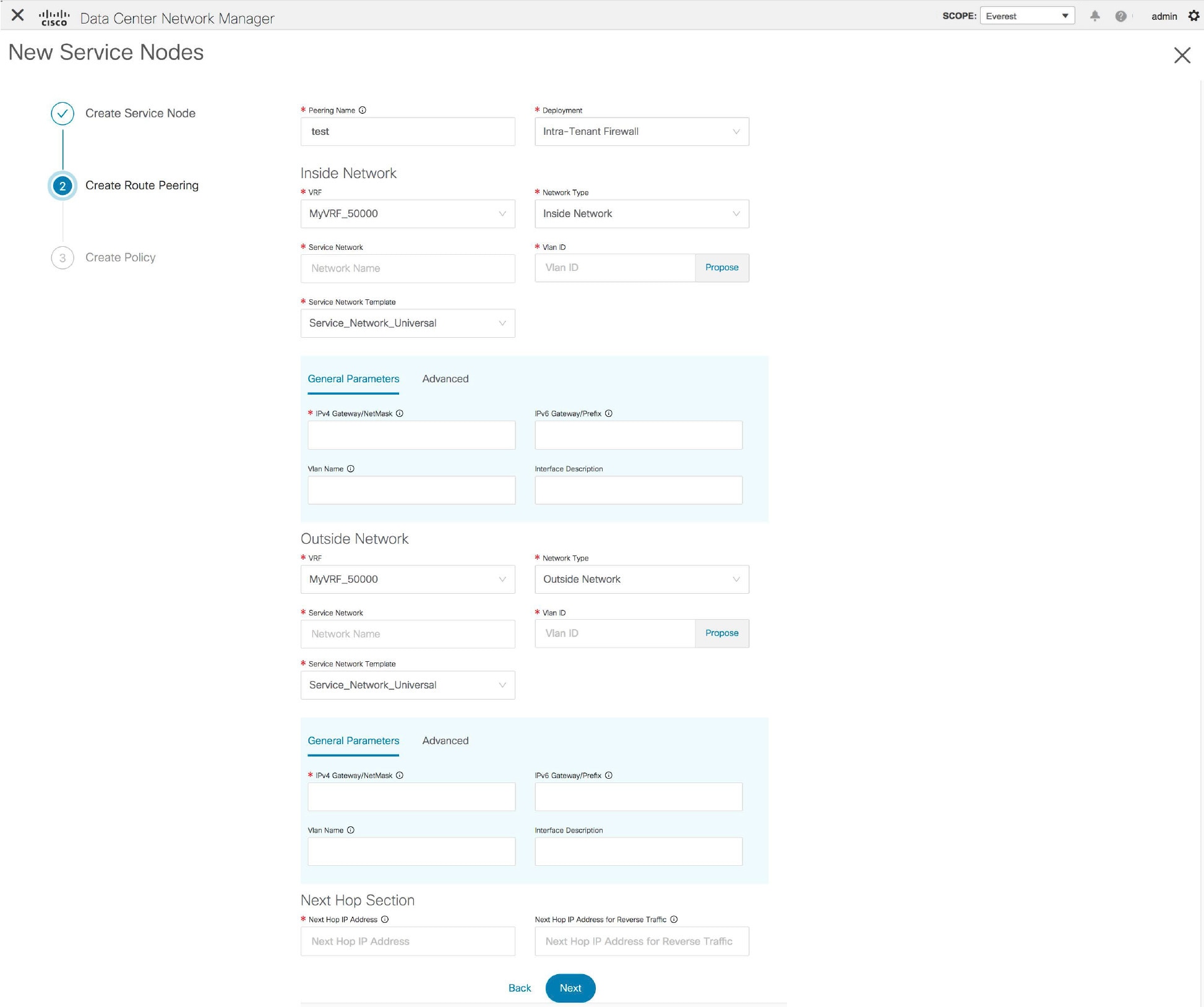
The fields in the Create Route Peering window for an Intra-Tenant Firewall deployment are as given below. It is mandatory to fill the fields marked with an asterisk. For more information on the fields in this window, hover over the i icon.
Peering Name - Specify a name for the peering. The name can have alphanumeric, underscore, or dash characters.
Deployment - Select Intra-Tenant Firewall.
Inside Network
VRF - Specify the VRF.
Network Type - Select Inside Network.
Service Network - Specify the name of the service network.
Vlan ID - Specify the VLAN ID. Valid IDs range from 2 to 3967. Click Propose to retrieve a value from the pre-defined service network VLAN range pool.
Service Network Template - Select the Service_Network_Universal template from the drop-down list. For more information on the template fields, refer Templates.
Outside Network
VRF - Specify the VRF.
Network Type - Select Outside Network.
Service Network - Specify the name of the service network.
Vlan ID - Specify the VLAN ID. Valid IDs range from 2 to 3967. Click Propose to retrieve a value from the pre-defined service network VLAN range pool.
Service Network Template - Select the Service_Network_Universal template from the drop-down list. For more information on the template fields, refer Templates.
Next Hop Section
Next Hop IP Address - Specify the next-hop IP address. This is the IP/VIP of the service node used for traffic redirection.
Next Hop IP Address for Reverse Traffic - Specify the next-hop IP address for reverse traffic. This is the IP/VIP of the service node used for traffic redirection.
Example: Inter-Tenant Firewall Deployment
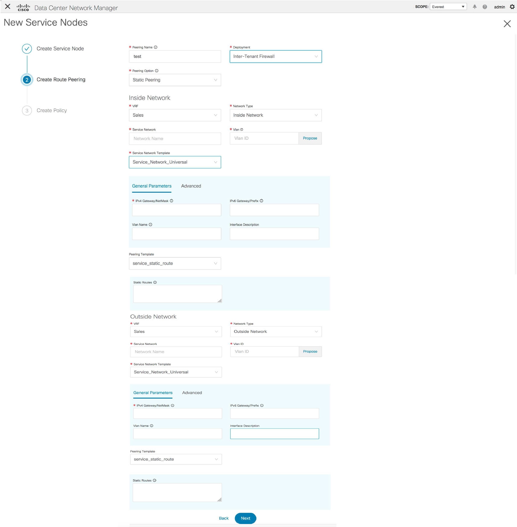
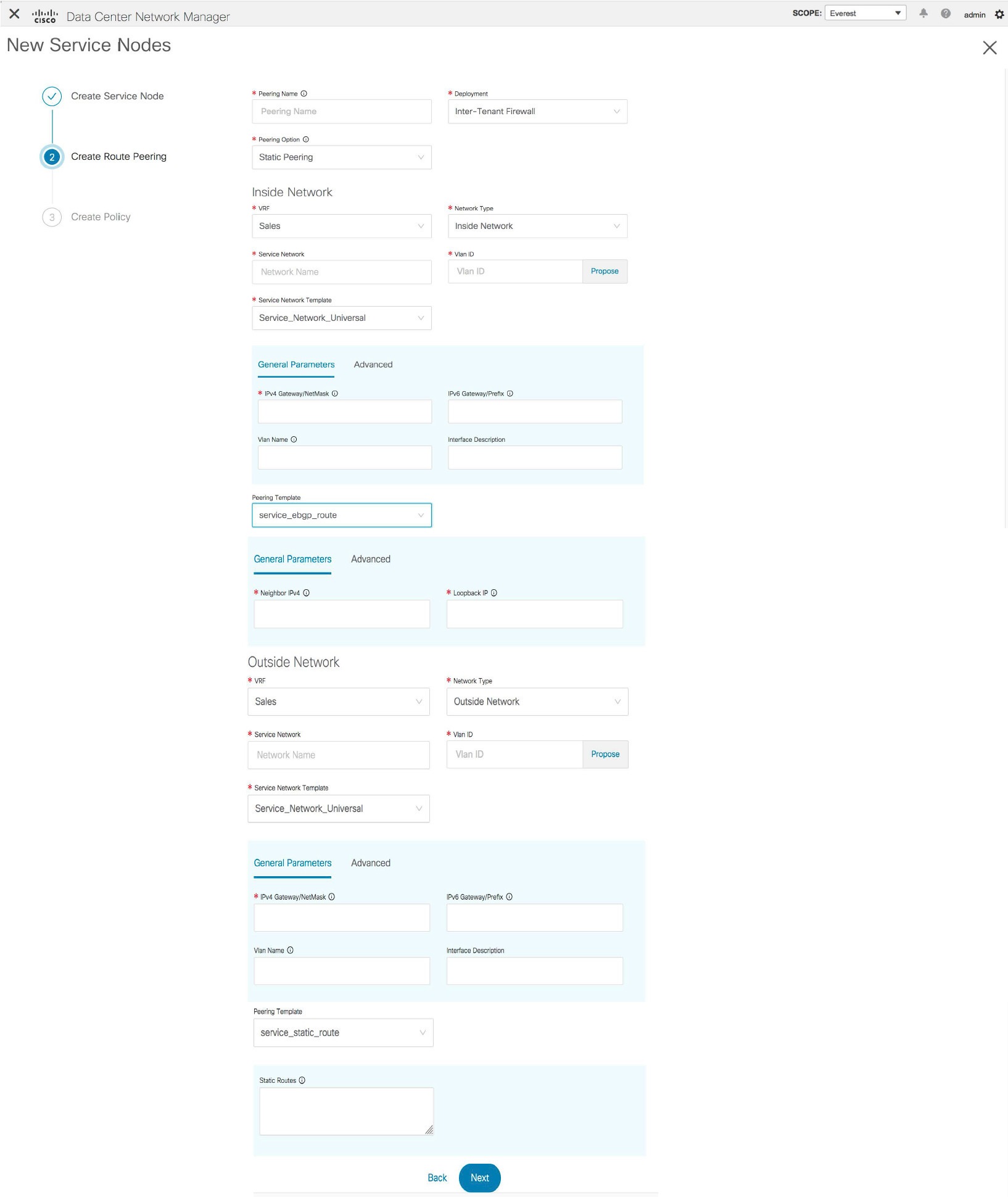
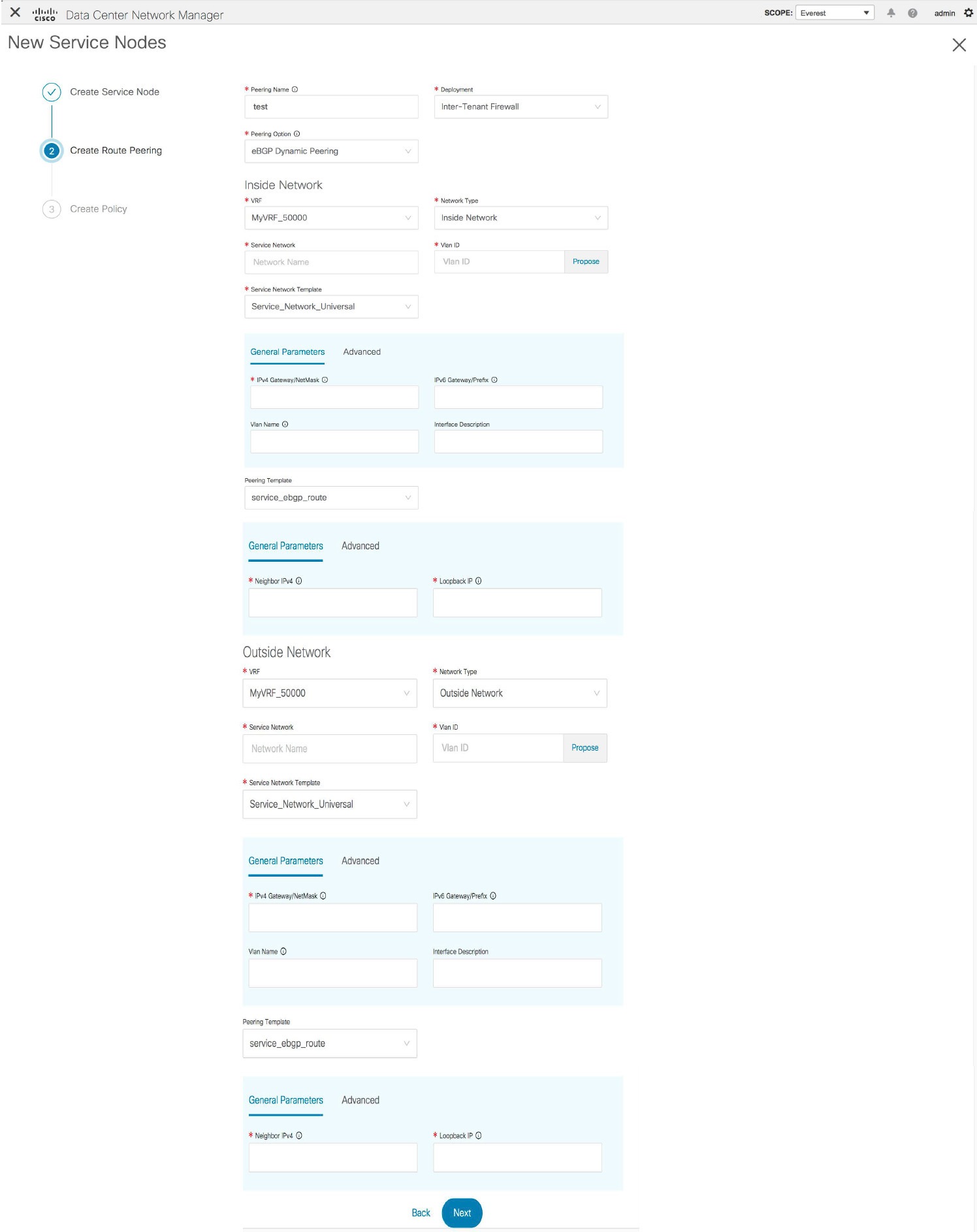
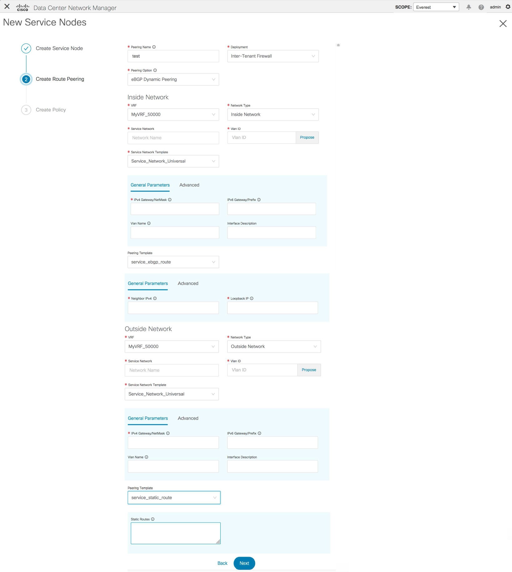
The fields in the Create Route Peering window for an Inter-Tenant Firewall deployment are as given below. It is mandatory to fill the fields marked with an asterisk.
Peering Name - Specify a name for the peering. The name can have alphanumeric, underscore, or dash characters.
Deployment - Select Inter-Tenant Firewall.
Peering Option - Select Static Peering or eBGP Dynamic Peering.
Inside Network
VRF - Select a VRF from the drop-down list..
Network Type - Select Inside Network.
Service Network - Select a service network name from the drop-down list.
Vlan ID - Specify the VLAN ID. Valid IDs range from 2 to 3967. Click Propose to retrieve a value from the pre-defined service network VLAN range pool.
Service Network Template - Select the Service_Network_Universal template from the drop-down list. For more information on the template fields, refer Templates.
Peering Template - Select service_static_route or service_ebgp_route from the drop-down list. For more information on the template fields, refer Templates.
Outside Network
VRF - Select a VRF from the drop-down list..
Network Type - Select Outside Network.
Service Network - Select a service network name from the drop-down list.
Vlan ID - Specify the VLAN ID. Valid IDs range from 2 to 3967. Click Propose to retrieve a value from the pre-defined service network VLAN range pool.
Service Network Template - Select the Service_Network_Universal template from the drop-down list. For more information on the template fields, refer Templates.
Peering Template - Select service_static_route or service_ebgp_route from the drop-down list. For more information on the template fields, refer Templates.
Example: One-Arm Mode Load Balancer
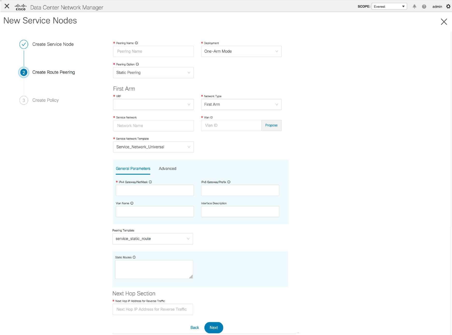
The fields in the Create Route Peering window for a One-Arm Mode load balancer deployment are as given below. It is mandatory to fill the fields marked with an asterisk.
Peering Name - Specify a name for the peering. The name can have alphanumeric, underscore, or dash characters.
Deployment - Select One-Arm Mode.
Peering Option - Select Static Peering or eBGP Dynamic Peering.
First Arm
VRF - Select a VRF from the drop-down list..
Network Type - Select First Arm.
Service Network - Select a service network name from the drop-down list.
Vlan ID - Specify the VLAN ID. Valid IDs range from 2 to 3967. Click Propose to retrieve a value from the pre-defined service network VLAN range pool.
Service Network Template - Select the Service_Network_Universal template from the drop-down list. For more information on the template fields, refer Templates.
Peering Template - Select service_static_route or service_ebgp_route from the drop-down list. For more information on the template fields, refer Templates.
Next Hop IP Address for Reverse Traffic - Specify the next-hop IP address for reverse traffic.
Example: Two-Arm Mode Load Balancer
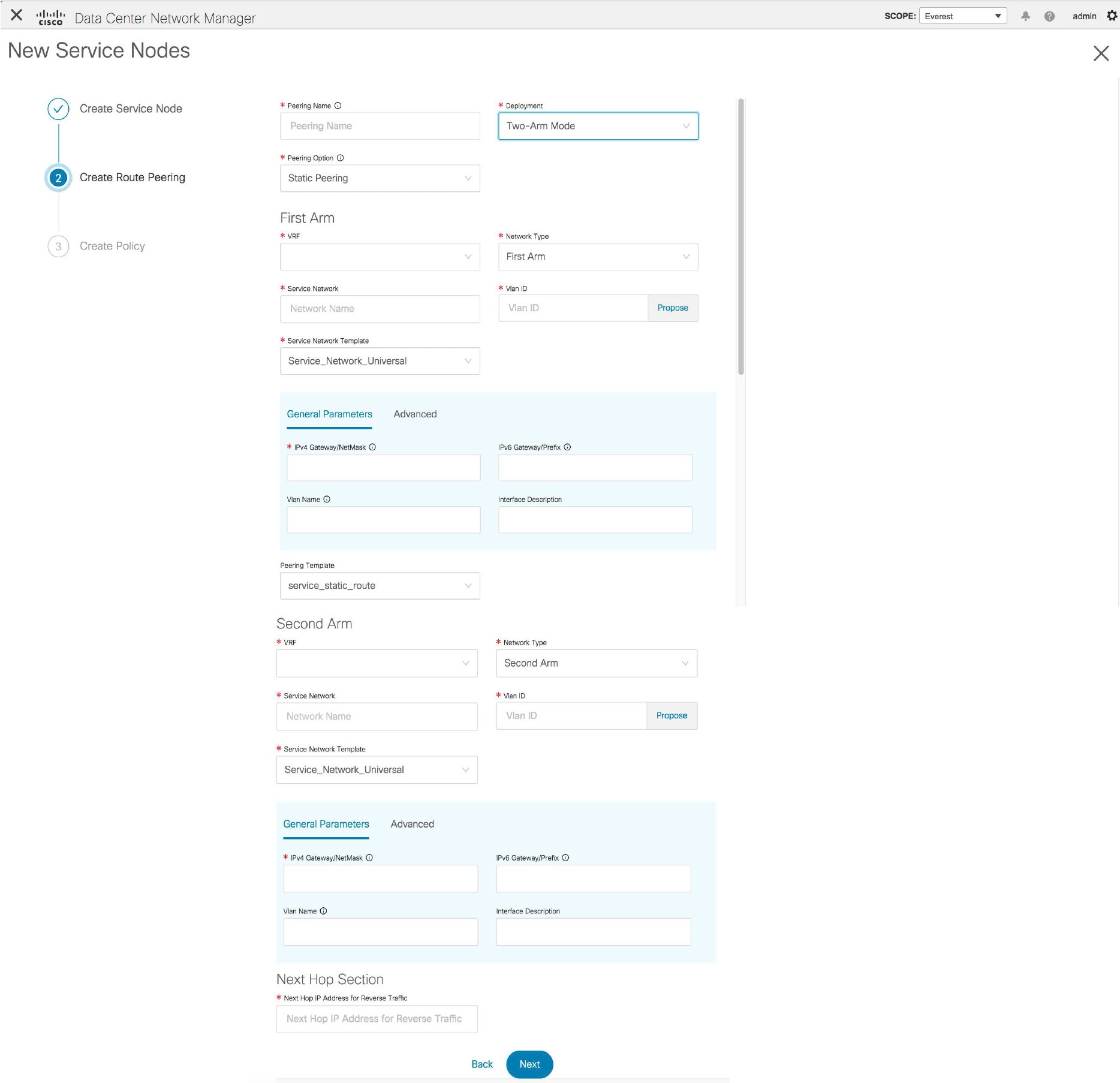
The fields in the Create Route Peering window for a Two-Arm Mode load balancer deployment are as given below. It is mandatory to fill the fields marked with an asterisk.
Peering Name - Specify a name for the peering. The name can have alphanumeric, underscore, or dash characters.
Deployment - Select Two-Arm Mode.
Peering Option - Select Static Peering or eBGP Dynamic Peering.
First Arm
VRF - Select a VRF from the drop-down list..
Network Type - Select First Arm.
Service Network - Select a service network name from the drop-down list.
Vlan ID - Specify the VLAN ID. Valid IDs range from 2 to 3967. Click Propose to retrieve a value from the pre-defined service network VLAN range pool.
Service Network Template - Select the Service_Network_Universal template from the drop-down list. For more information on the template fields, refer Templates.
Peering Template - Select service_static_route or service_ebgp_route from the drop-down list. For more information on the template fields, refer Templates.
Second Arm
VRF - Select a VRF from the drop-down list..
Network Type - Select Second Arm.
Service Network - Specify the name of the service network.
Vlan ID - Specify the VLAN ID. Valid IDs range from 2 to 3967. Click Propose to retrieve a value from the pre-defined service network VLAN range pool.
Service Network Template - Select the Service_Network_Universal template from the drop-down list. For more information on the template fields, refer Templates.
Next Hop Section
Next Hop IP Address for Reverse Traffic - Specify the next-hop IP address for reverse traffic.
Now, click Next. The Create Policy window is displayed.
Create Service Policy
The Create Policy window is displayed as given below.
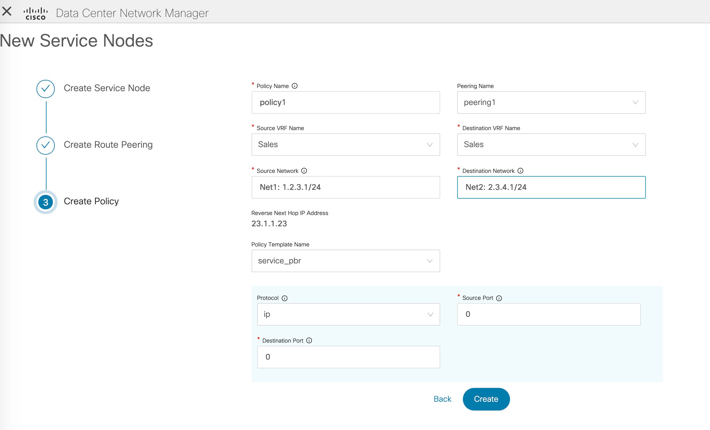
The fields in the Create Policy window are as given below. It is mandatory to fill the fields marked with an asterisk.
Policy Name - Specify a name for the policy.
Peering Name - Select a peering option from the drop-down list.
Source VRF Name - Select a source VRF from the drop-down list.
Destination VRF Name - Select a destination VRF from the drop-down list.
Source Network - Select an IP address from the drop-down list.
Destination Network - Select an IP address from the drop-down list.
Reverse Next Hop IP Address - The reverse next-hop IP address is displayed.
Policy Template Name - Select a template from the drop-down list. For more information on the template fields, refer Templates.
Protocol - Select a protocol from the drop-down list. The options are icmp, ip, tcp, and udp.
Source Port - Specify a source port number. In case the ip protocol is selected, this value is ignored.
Destination Port - Specify a destination port number. In case the ip protocol is selected, this value is ignored.
Click Create. The service policy is created.
Note |
Deletion of any service network in Top-Down provisioning that is used by Services is not allowed. Deletion of any regular network that is used in a service policy is also not allowed. |
Templates
Service Node Link Templates
service_link_trunk
General Parameters tab
MTU - Specifies the MTU for the interface. By default, this is set to jumbo.
SPEED - Specifies the speed of the interface. By default, this is set to Auto. You can change it to 100Mb, 1Gb, 10GB, 25Gb, 40Gb, or 100Gb, as required.
Trunk Allowed Vlans - Specify 'none',' all' or VLAN ranges. By default, none is specified.
Enable BPDU Guard - Specify an option from the drop-down list. The available options are true, false or no.
Enable Port Type Fast - Select the checkbox to enable spanning tree edge port behavior. By default, this is enabled.
Enable Interface - Uncheck the checkbox to disable the interface. By default, the interface is enabled.
Advanced tab
Source Interface Description - Enter a description for the source interface.
Destination Interface Description - Enter a description for the destination interface.
Source Interface Freeform Config - Enter any addition CLI for the source interface.
Destination Interface Freeform Config - Enter any addition CLI for the destination interface.
service_link_port_channel_trunk
Port Channel Mode - Select a port channel mode from the drop-down list. By default, active is specified.
Enable BPDU Guard - Specify an option from the drop-down list. The available options are true, false or no.
MTU - Specifies the MTU for the interface. By default, this is set to jumbo.
Trunk Allowed Vlans - Specify 'none',' all' or VLAN ranges. By default, none is specified.
Port Channel Description - Enter a description for the port channel.
Freeform Config - Specify the required freeform configuration CLIs.
Enable Port Type Fast - Select the checkbox to enable spanning tree edge port behavior. By default, this is enabled.
Enable Port Channel - Select the checkbox to enable the port channel. By default, this is enabled.
service_link_vpc
This template has no specifiable parameters.
Route Peering Service Network Template
Service_Network_Universal
General Parameters tab
IPv4 Gateway/Netmask - Specify the gateway IP address and mask of the service network.
IPv6 Gateway/Prefix - Specify the gateway IPv6 address and prefix of the service network.
Vlan Name - Specify a name for the VLAN.
Interface Description - Enter a description for the interface
Advanced tab
Routing Tag - Specify a routing tag. Valid values range from 0 to 4294967295.
Route Peering Templates
-
Name of the template - service_ebgp_route
service_static_route
Enter the static routes in the Static Routes field. You can enter one static route per line.
service_ebgp_route
General Parameters tab
Neighbor IPv4 - Specify the IPv4 address of the neighbor.
Loopback IP - Specify the IP address of the loopback.
Advanced tab
Neighbor IPv6 - Specify the IPv6 address of the neighbor.
Loopback IPv6 - Specify the IPv6 address of the loopback.
Route-Map TAG - Specify route-map tag that is associated with the interface ID.
Interface Description - Enter a description for the interface.
Enable Interface - Uncheck the checkbox to disable the interface. By default, the interface is enabled.
Service Policy Template
service_pbr
Protocol - Select a protocol from the drop-down list. The options are icmp, ip, tcp, and udp.
Source port - Specify a source port number. In case the ip protocol is selected, this value is ignored.
Destination port - Specify a destination port number. In case the ip protocol is selected, this value is ignored.
You can also customize the templates based on specific requirements. For more information on templates, refer Template Library.
Adding a Route Peering
Procedure
| Step 1 |
Click the Add Route Peering icon on the Service Nodes window. 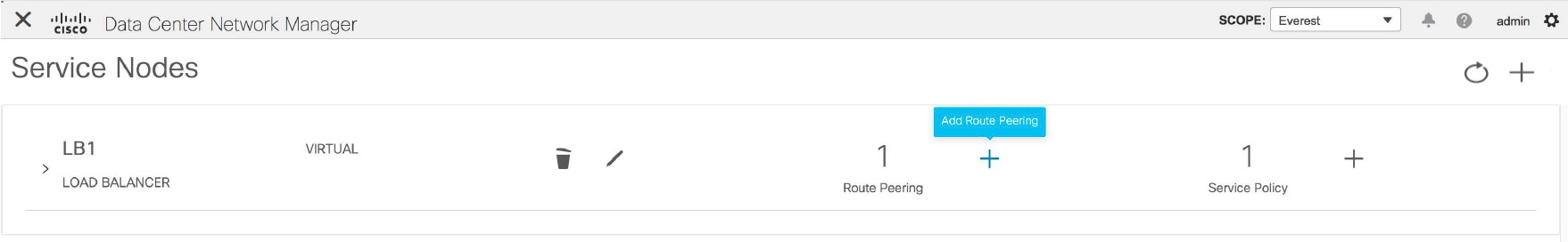 |
| Step 2 |
The Add Route Peering window is displayed. 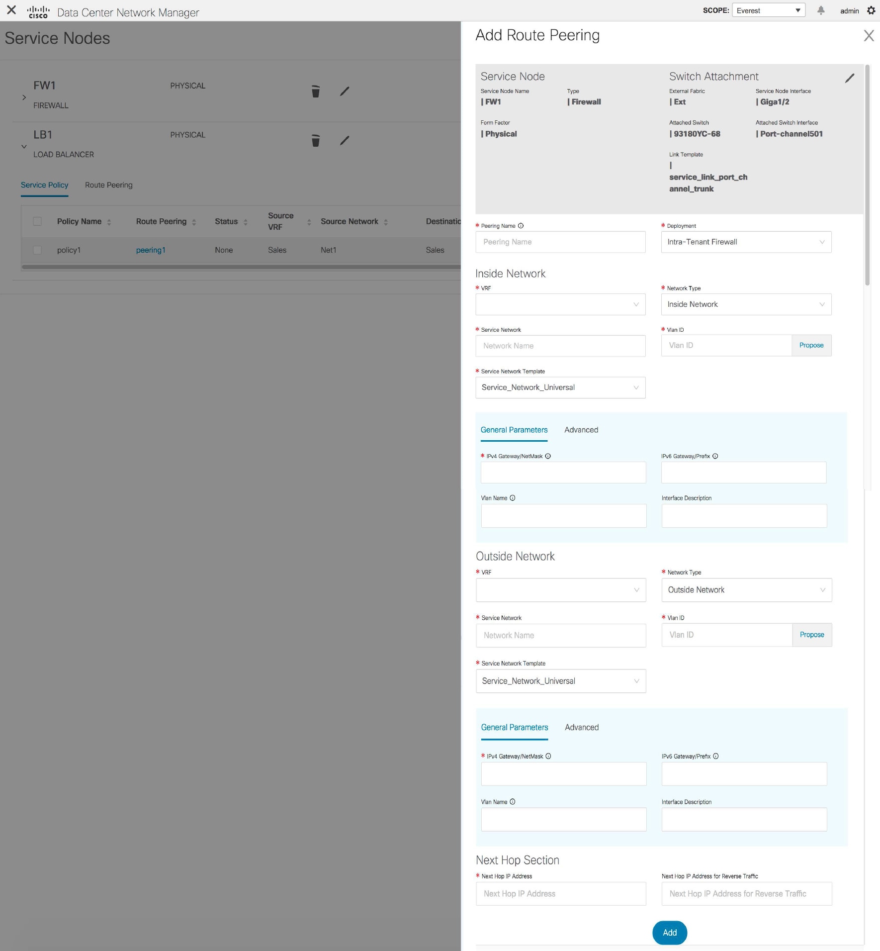 Specify the required parameters and click Add. For more information on specific fields, hover over the i icon. |
Adding a Service Policy
Procedure
| Step 1 |
Click the Add Service Policy icon on the Service Nodes window. 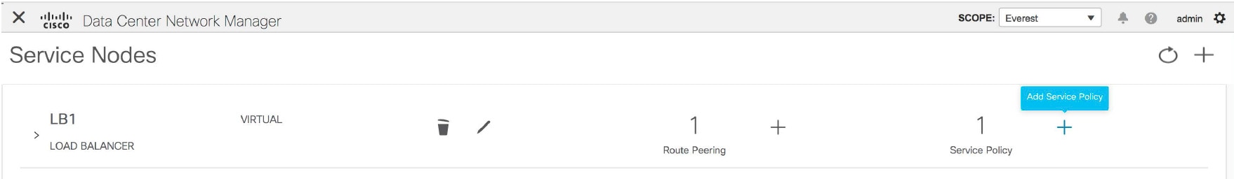 |
| Step 2 |
The Add Service Policy window is displayed. 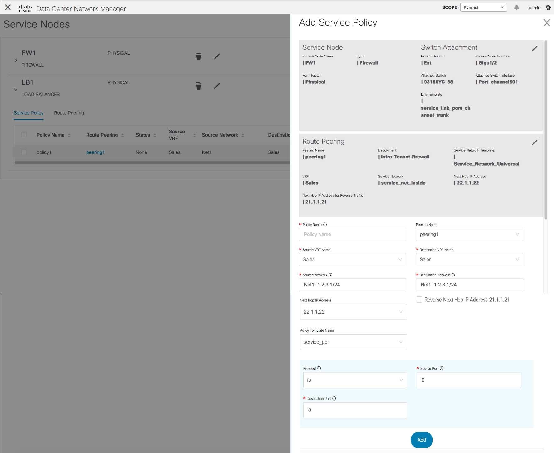 Specify the required parameters and click Add. For more information on specific fields, hover over the i icon. |
Deleting a Service Node
Procedure
| Step 1 |
Click the Delete Service Node icon on the Service Nodes window. 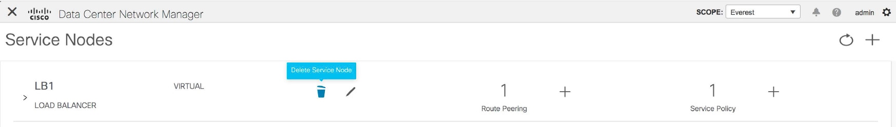 |
||
| Step 2 |
A pop-up window comes up to confirm if the node has to be deleted. Click Delete.
|
Editing a Service Node
Procedure
| Step 1 |
Click the Edit Service Node icon on the Service Nodes window. 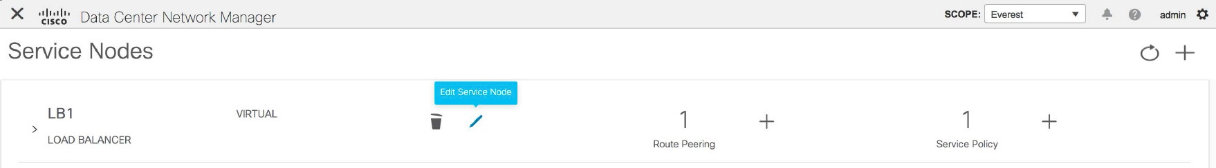 |
| Step 2 |
The Edit Service Node window is displayed. 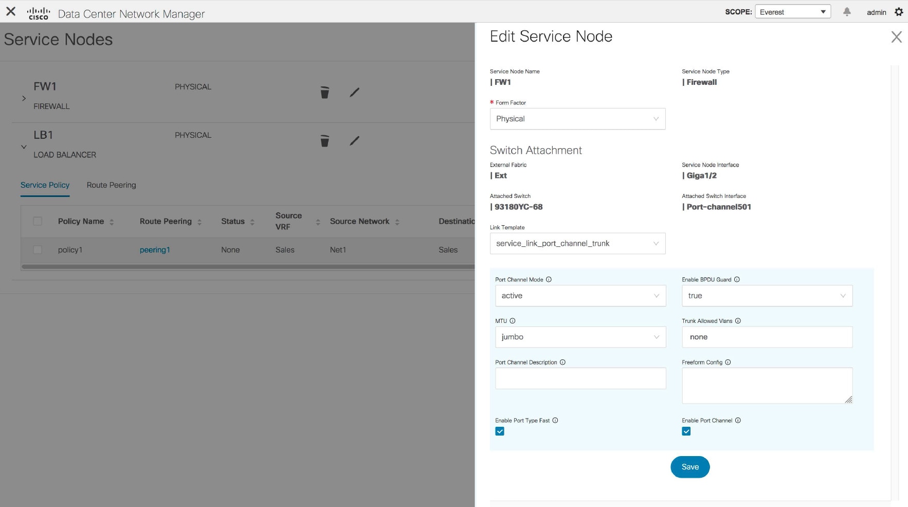 Make the required changes and click Save. |
Preview a Service Policy or a Route Peering
Procedure
| Step 1 |
Select a service policy or route peering checkbox and click Preview on the Service Nodes window. 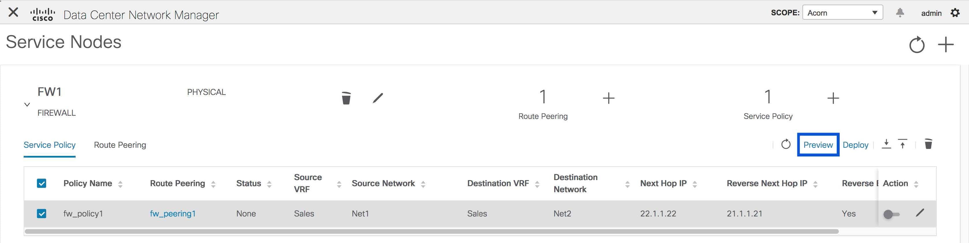 A Preview Service Policy or a Preview Route Peering window is displayed. 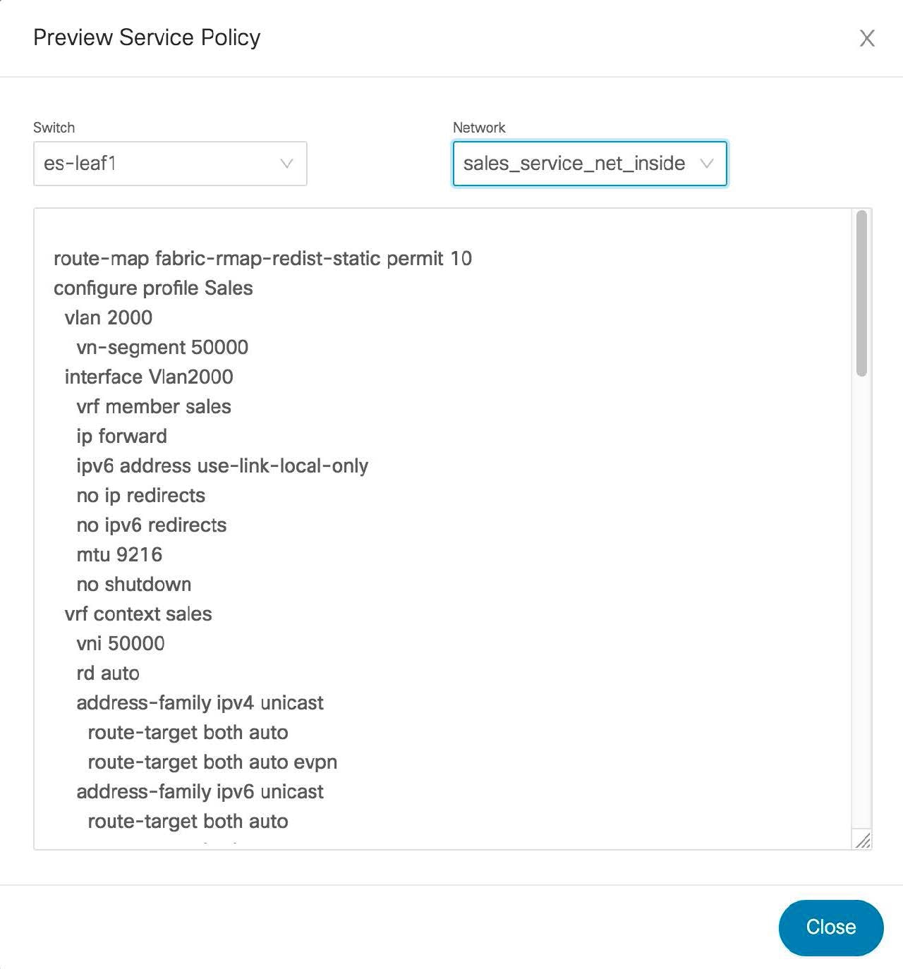 |
| Step 2 |
Select a specific switch or network from the respective drop-down lists to display the service policies or route peerings for specific switches and networks. Click Close to close the window. |
Deploying a Service Policy or a Route Peering
Procedure
| Step 1 |
Select a service policy or route peering checkbox and click Deploy on the Service Nodes window. A pop-up window is displayed asking for confirmation to deploy. 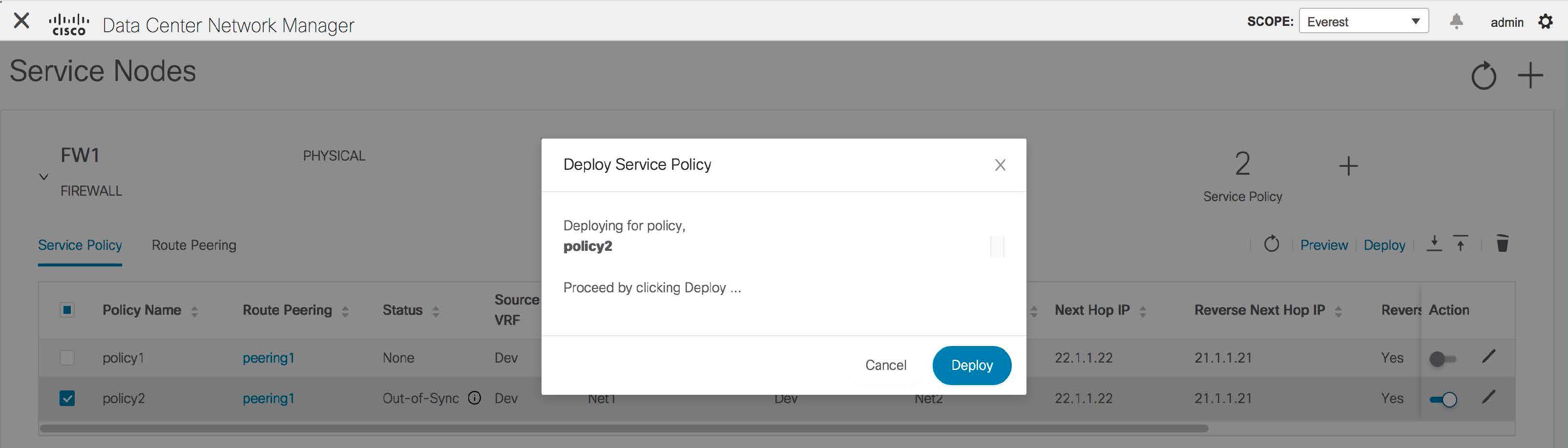 |
| Step 2 |
Click Deploy. |
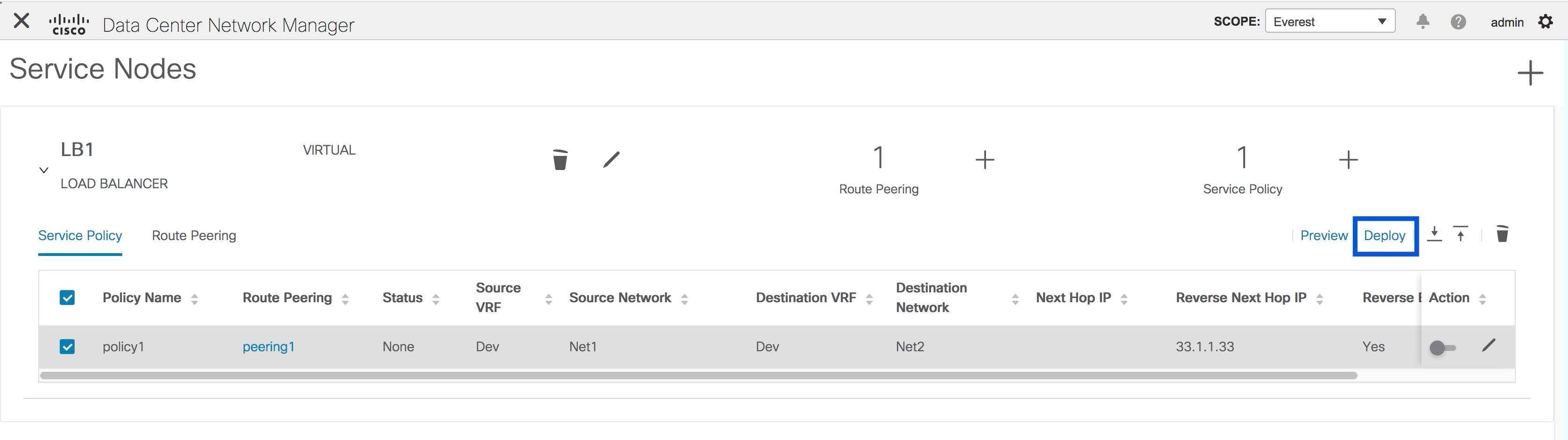
Exporting a Service Policy or a Route Peering Table
To export the service policy or route peering information as an Excel file, click the Export icon on the Service Nodes window. Click the Export icon on the Service Policy tab to export information about the service policies. Click the Export icon on the Route Peering tab to export information about the route peerings.
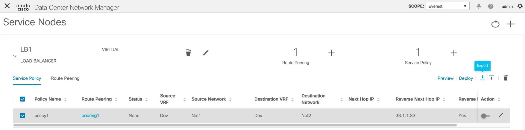
Importing a Service Policy or a Route Peering Table
To import service policy or route peering information as an Excel file, click the Import icon on the Service Nodes window. Click the Import icon on the Service Policy tab to export information about the service policies. Click the Import icon on the Route Peering tab to export information about the route peerings.
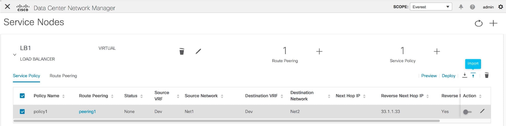
Deleting a Service Policy
Procedure
| Step 1 |
Select the service policy that has to be deleted by clicking the checkbox that is next to the name of the policy, and then click the Delete icon on the Service Nodes window. 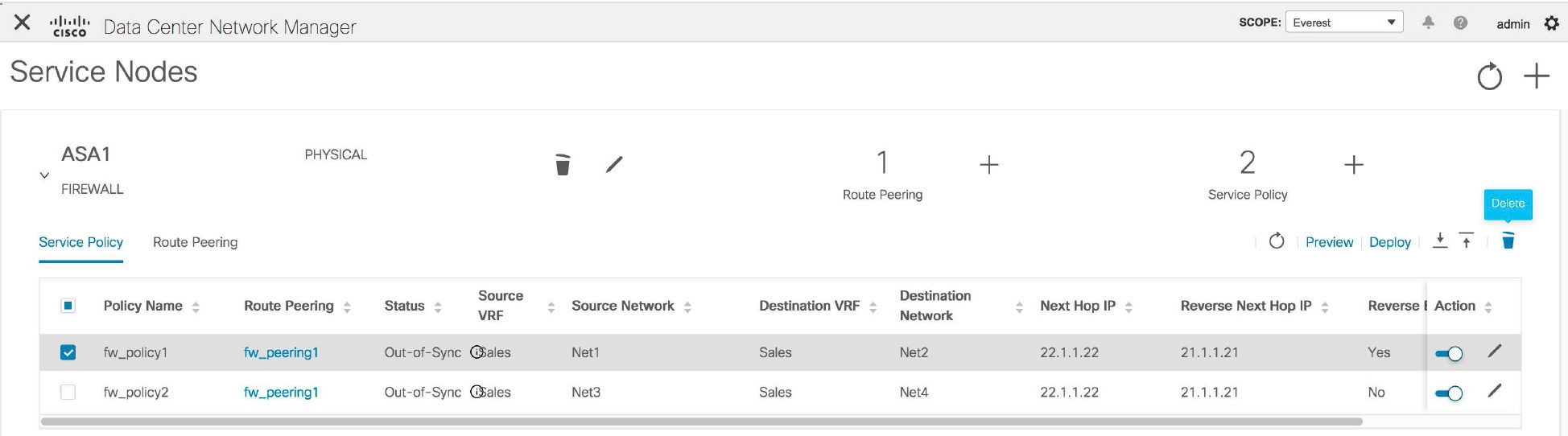 |
| Step 2 |
A pop-up window is displayed asking for confirmation to delete. Click Delete.In case the service policy that has to be deleted is attached, the pop-up window indicates that the service policy has to be detached by using the toggle in the Action column, and deploying the changes (removing the policy) before it can be deleted.  |
Deleting a Route Peering
Procedure
| Step 1 |
Select the route peering that has to be deleted by clicking the checkbox that is next to the name of the route peering, and then click the Delete icon on the Service Nodes window. 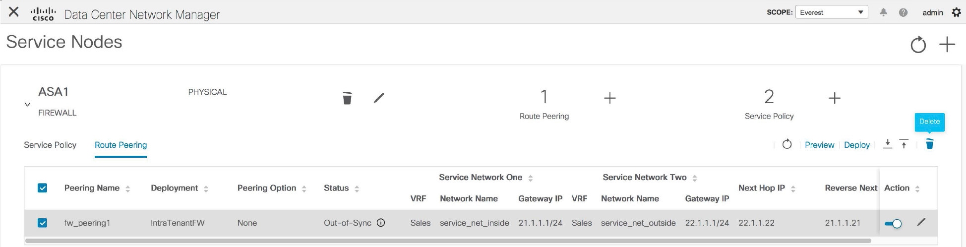 |
| Step 2 |
A pop-up window is displayed asking for confirmation to delete. Click Delete. In case the route peering that has to be deleted is attached or if the service policy associated with the route peering is active, the pop-up window indicates that the peering has to be detached by using the toggle in the Action column, deploy the changes (remove the policy), and delete the service policy associated with the route peering before the route peering can be deleted. 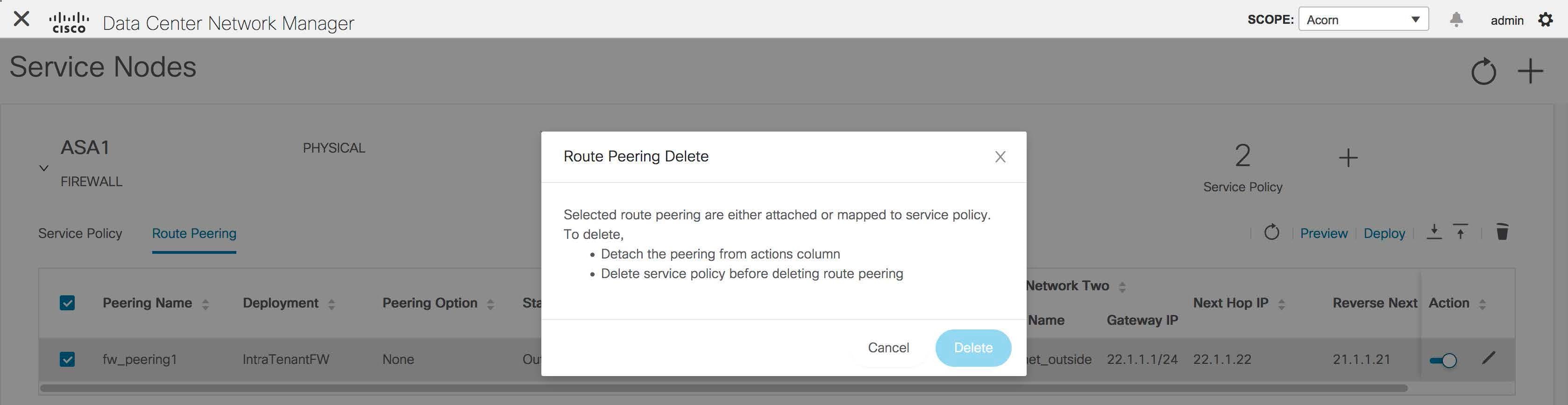 |
Viewing Service Policy Information
In the Service Nodes window, the Service Policy tab displays information about the configured service policies.
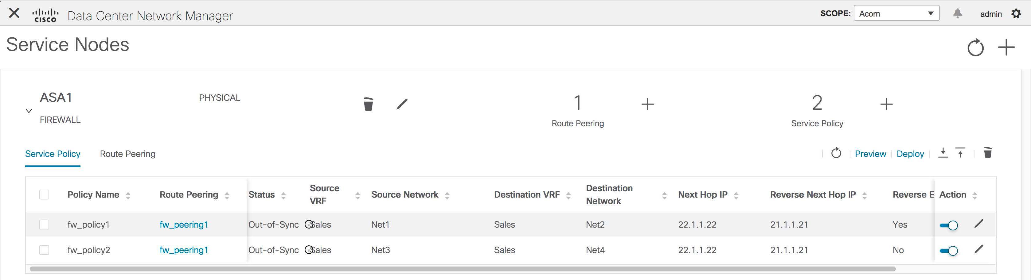
|
Field |
Description |
|---|---|
|
Policy Name |
Displays the name of the policy. |
|
Route Peering |
Displays the route peering name given for the peering configuration. Click the specified peering name to display route peering information. |
|
Status |
Displays the status of the service policy. |
|
Source VRF |
Displays the Virtual Routing and Forwarding (VRF) source. |
|
Source Network |
Displays the source network. |
|
Destination VRF |
Displays the destination VRF. |
|
Destination Network |
Displays the destination network. |
|
Next Hop IP |
Displays the next-hop IP address. |
|
Reverse Next Hop IP |
Displays the reverse next-hop IP address. |
|
Reverse Enabled |
Displays if reverse next-hop is enabled or not. |
|
Last Updated |
Displays the time at which the service policy was last updated. |
|
Stats |
Click the graph line to display cumulative statistics for a policy in a specified time range. For more information, refer Stats. |
|
Action |
Use the toggle to enable/attach or disable/detach the service policy. When the service policy is attached or enabled, the corresponding policies are applied to the VRF (tenant), source, and destination networks. 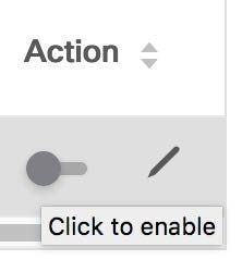 The toggle turns blue in color when the service policy is attached or enabled. 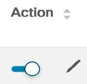 Click the Edit icon to edit the service policy.  |
Stats
In the Service Nodes window, the Service Policy tab displays statistical information about the configured service policies. Select a time range for which the statistics should be displayed from the Time Range drop-down box. You can select the date from the calendar displayed on the window and the time by clicking select time at the bottom right corner of the window. You can also display statistics from the last 15 minutes, 1 hour, 6 hours, 1 day, 1 week, and 1 month. Select the required time range and click Apply. Select a switch for which the statistics should be displayed from the Switch drop-down list. The statistics are then displayed for the selected switch in the specified time range.
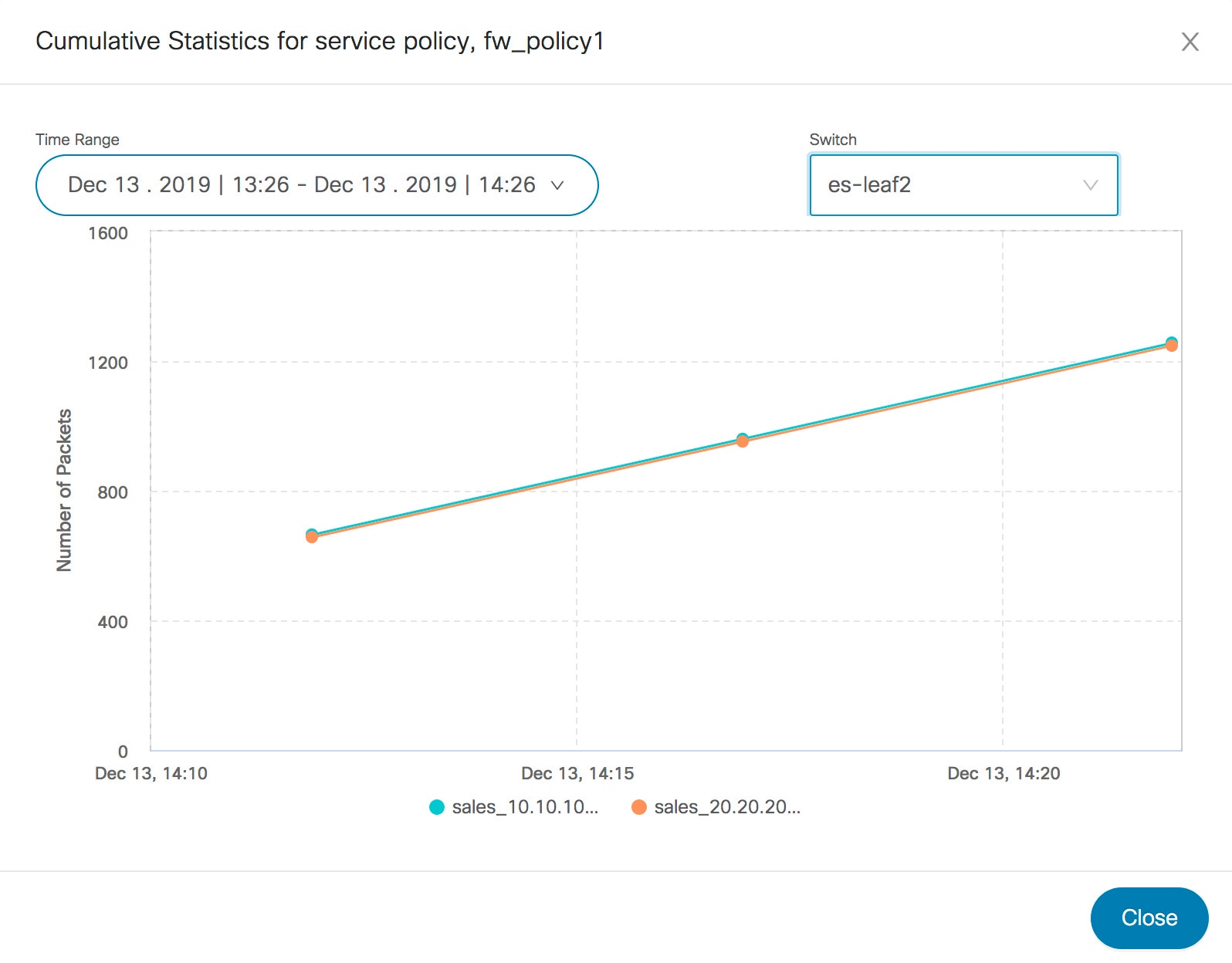
Viewing Route Peering Information
In the Service Nodes window, click Route Peering. The Route Peering tab displays route peering information.
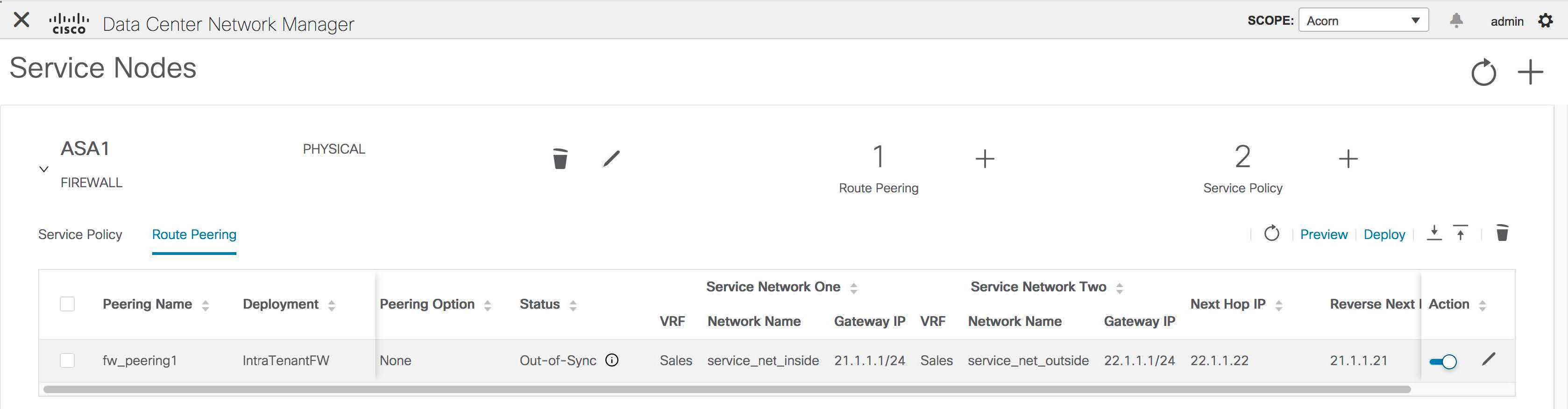
|
Field |
Description |
|---|---|
|
Peering Name |
Displays the defined peering name. |
|
Deployment |
Displays the deployment - One-Arm mode or Two-Arm mode. |
|
Peering Option |
Displays the peering option - Static or eBGP Dynamic peering. |
|
Status |
Displays the status of the route peering. |
|
Service Network VRF |
Displays the service network VRF. |
|
Service Network Name |
Displays the name of the service network. |
|
Service Network Gateway IP |
Displays the gateway IP of the service network VRF. |
|
Next Hop IP |
Displays the next-hop IP address. |
|
Reverse Next Hop IP |
Displays the reverse next-hop IP address. |
|
Last Updated |
Displays the time at which the route peering was last updated. |
|
Action |
Use the toggle to enable/attach or disable/detach the route peering. When the route peering is enabled, the service networks defined in that route peering will be attached to the service leaf. The toggle turns blue in color when the route peering is attached or enabled. Click the Edit icon to edit the route peering.  |
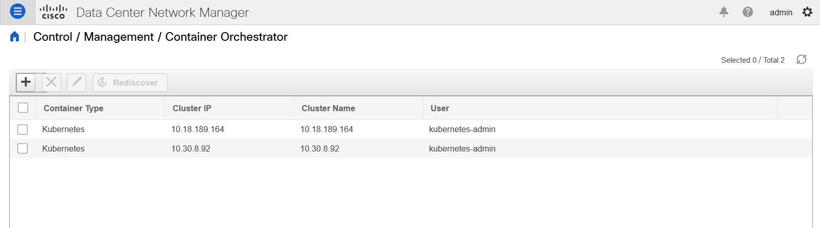
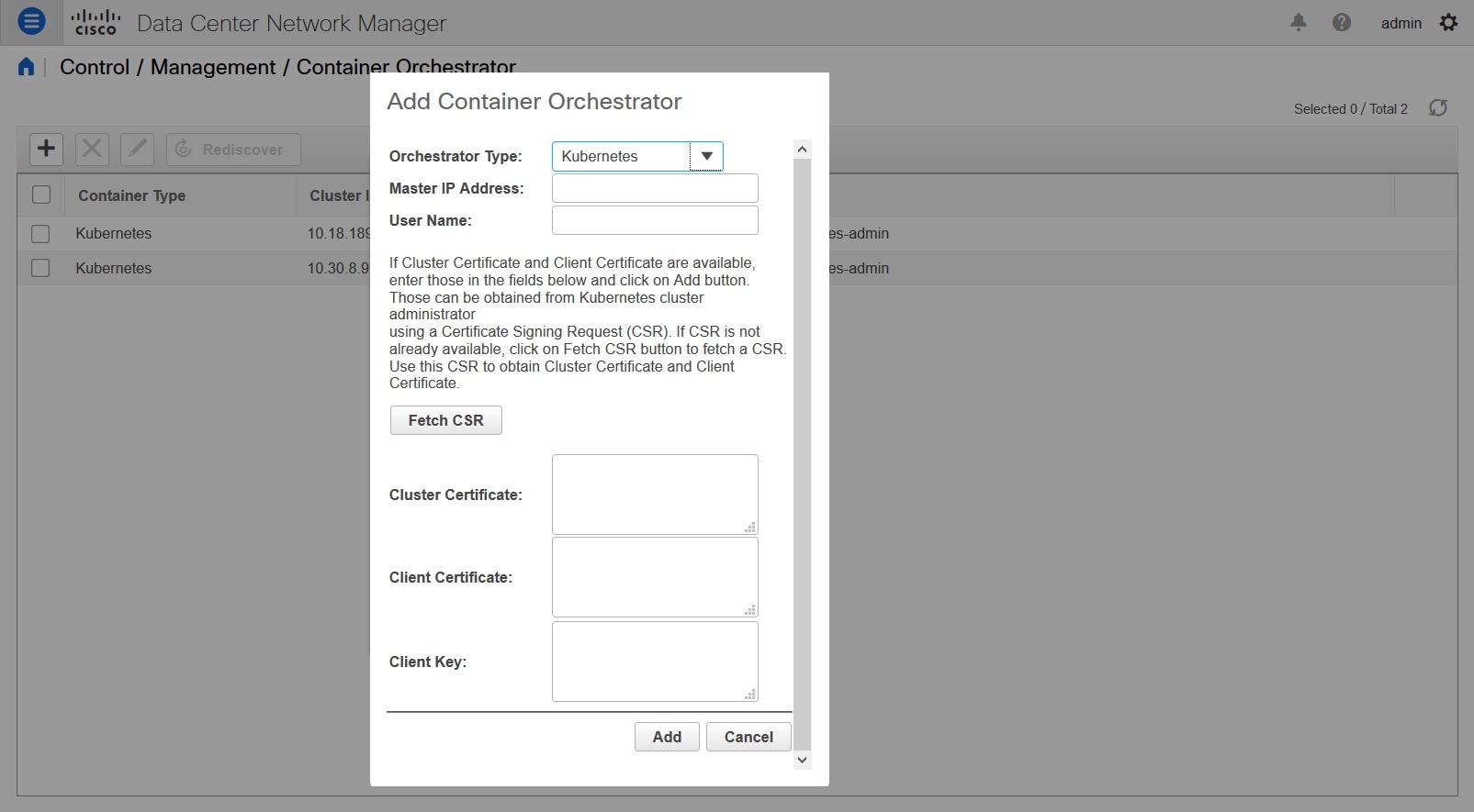
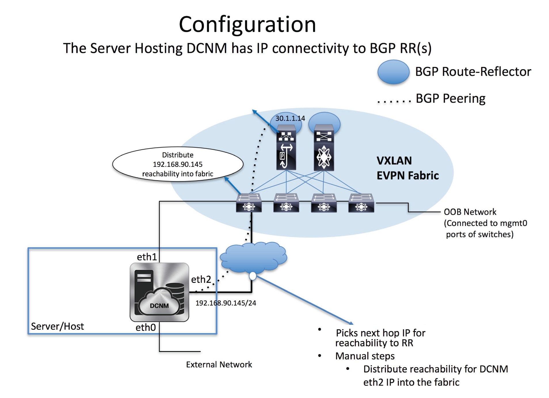
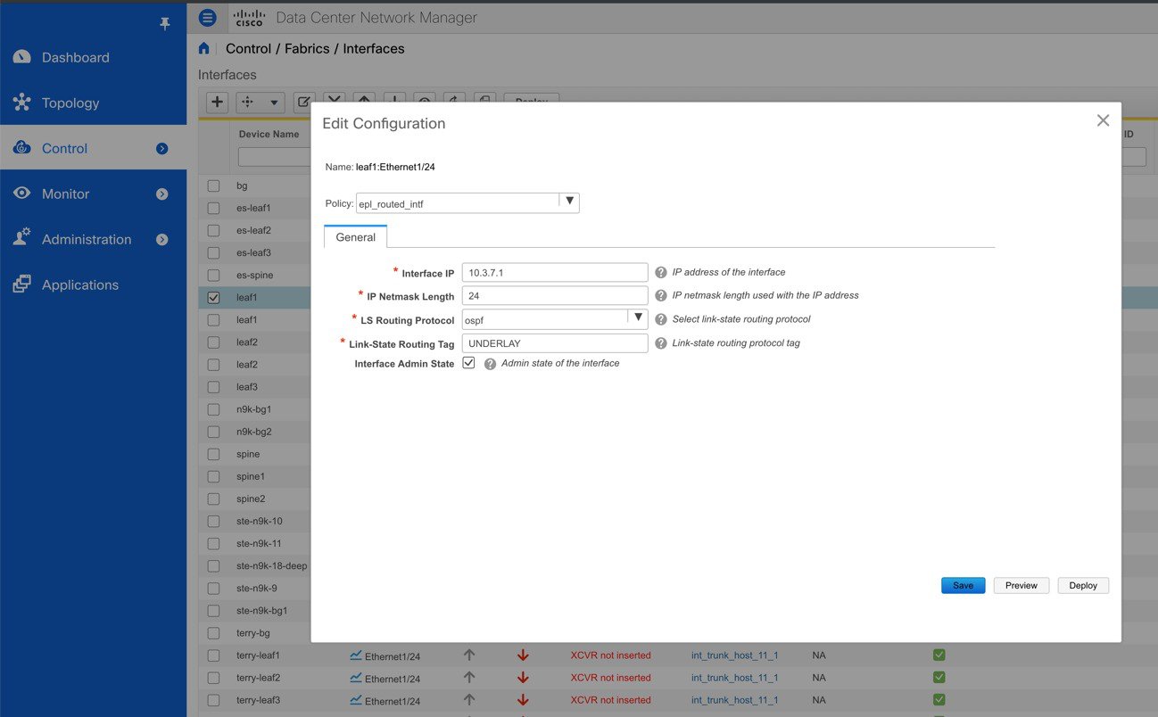
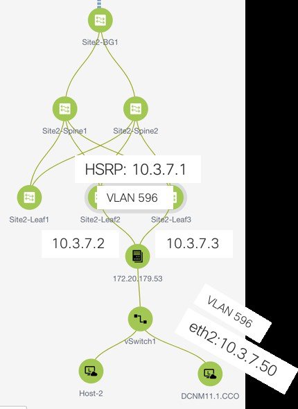
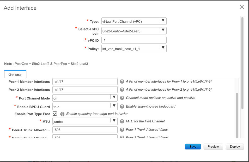
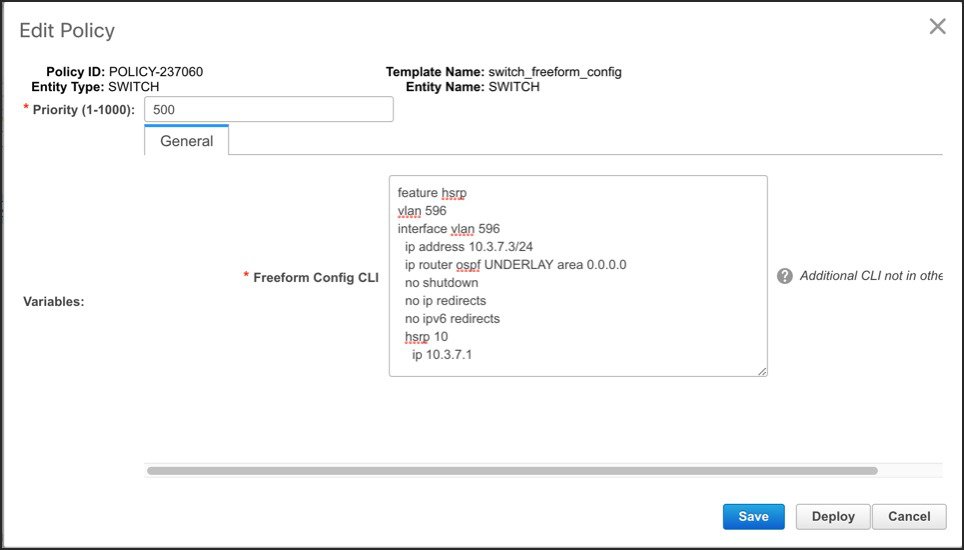

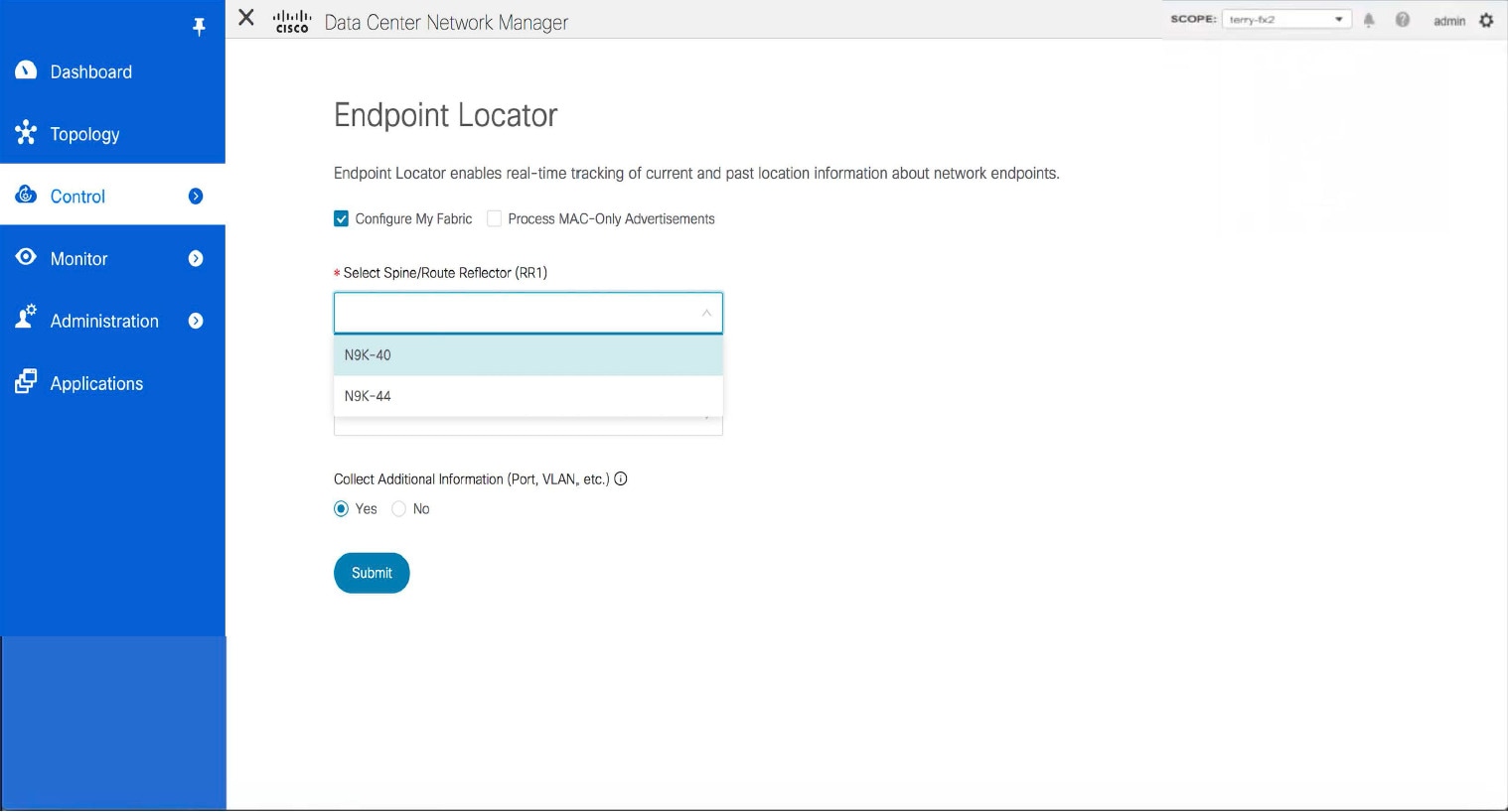
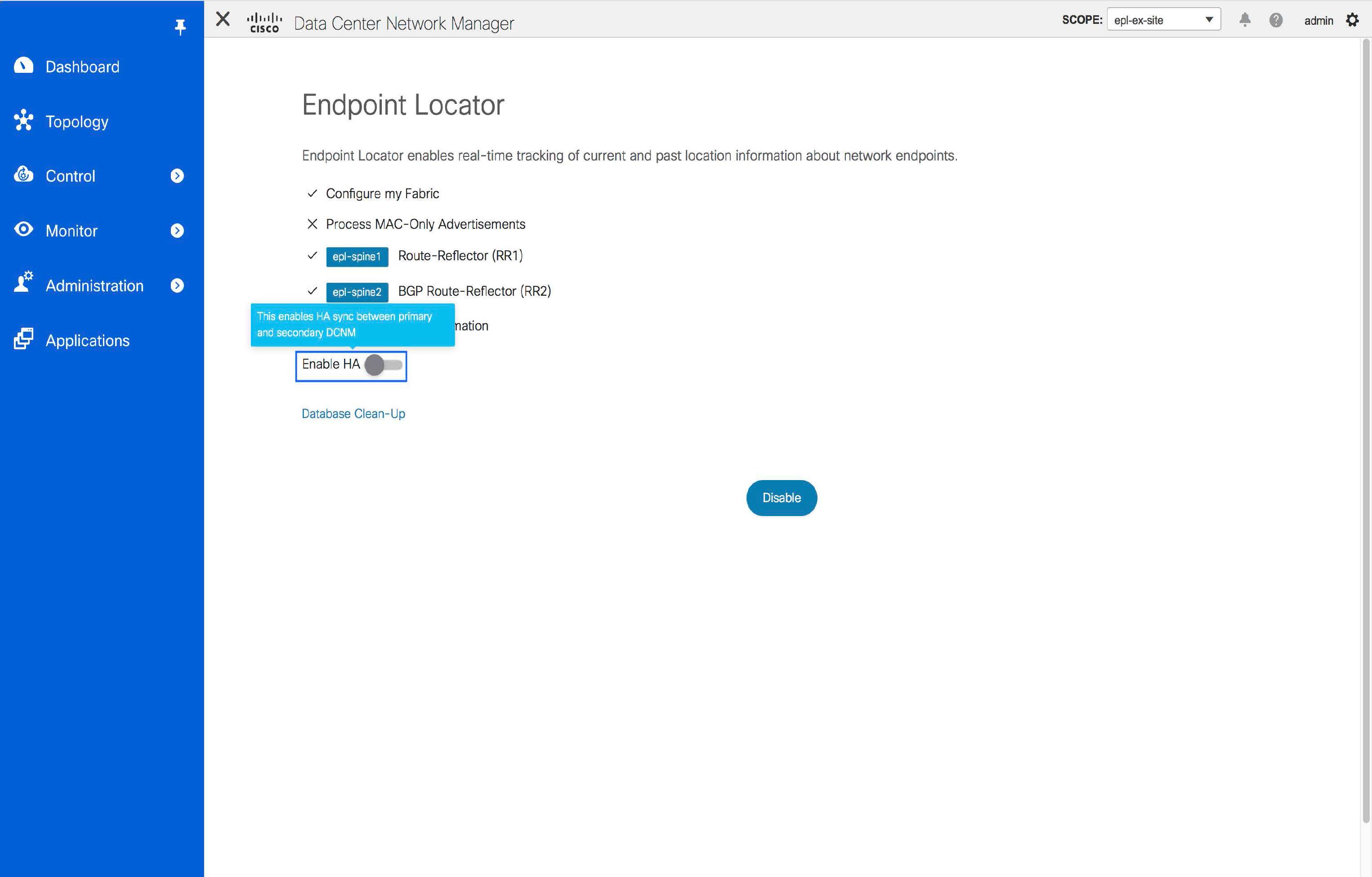

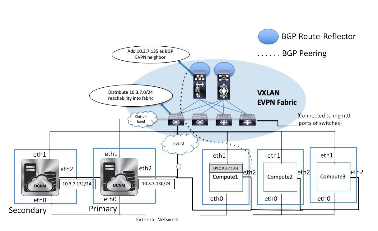

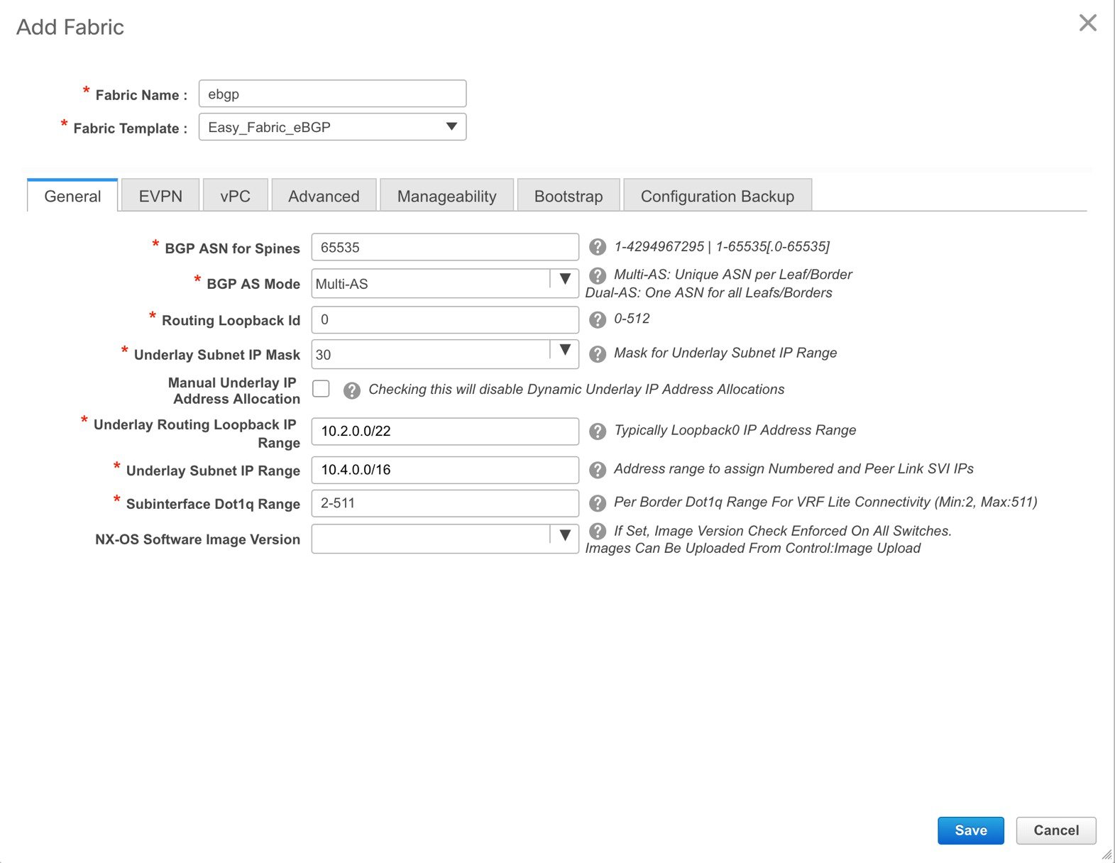
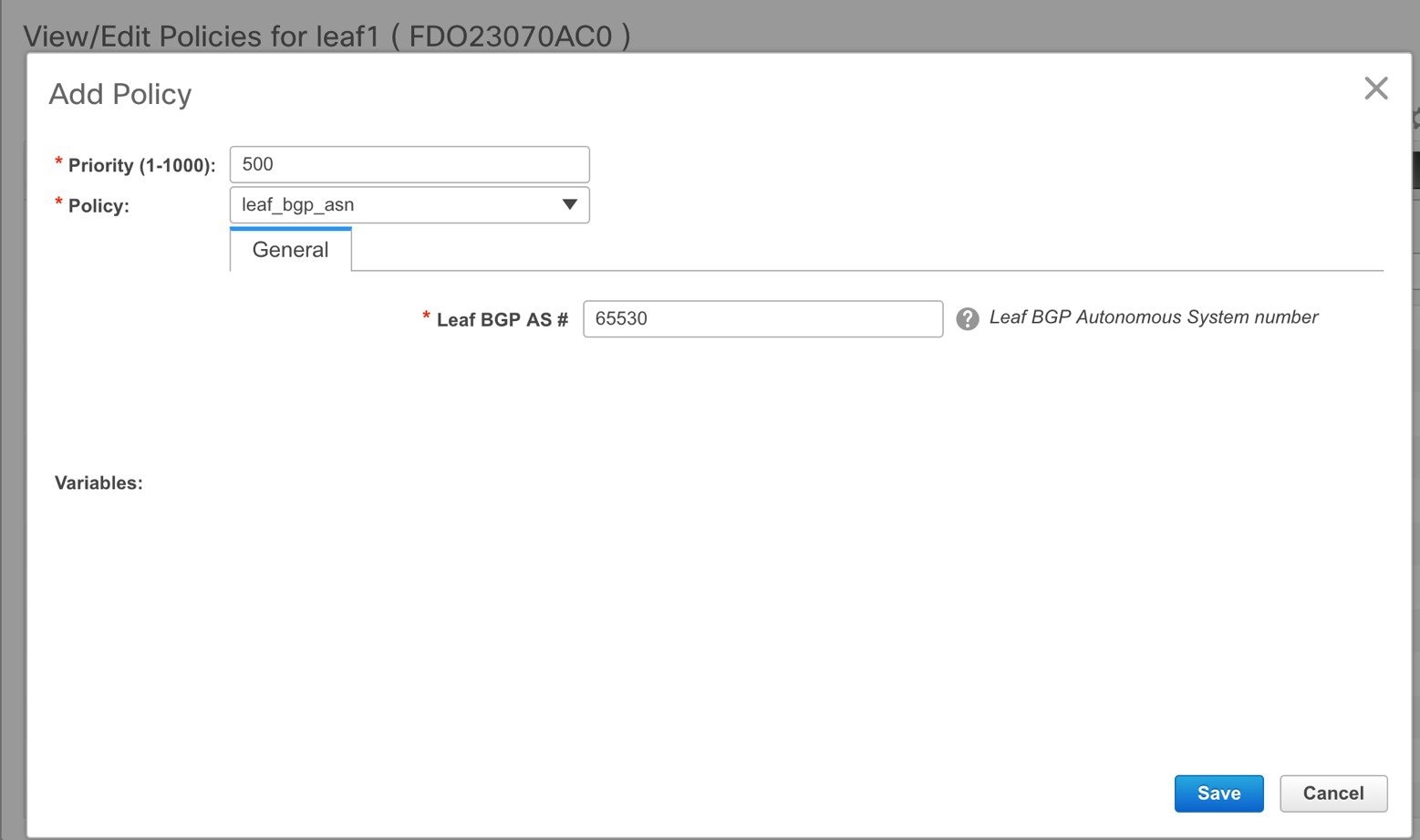
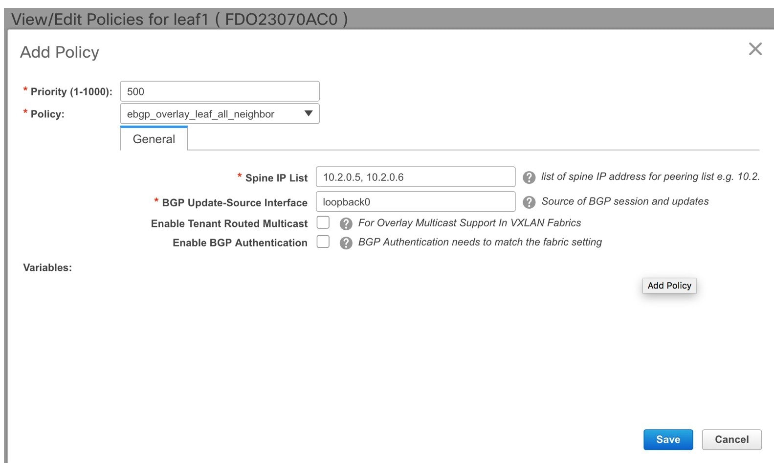
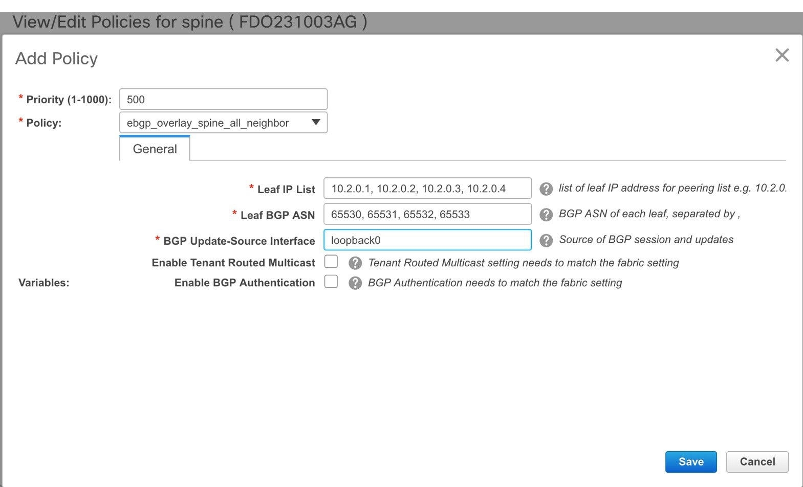
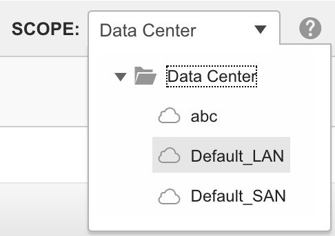
 Feedback