DCNM Server
The DCNM Server menu includes the following submenus:
Starting, Restarting, and Stopping Services
By default, the ICMP connectivity between DCNM and its switches validates the connectivity during Performance Management. If you disable ICMP, Performance Management data will not be fetched from the switches. You can configure this parameter in the server properties. To disable ICMP connectivity check from Cisco DCNM Web UI, choose Administration > DCNM Server > Server Properties, and set skip.checkPingAndManageable parameter value to true.
To clean up the performance manager database (PM DB) stale entries, start, restart, or stop a service, from the Cisco DCNM Web UI, perform the following steps:
 Note |
During restart, the Performance Manager waits for 20minutes for the Elasticsearch to become operational. After 20minutes, the Performance Manager aborts. Click the Re-init Elasticsearch DB Schema icon in the Actions column for the Performance collector service. |
Procedure
| Step 1 |
Choose Administration > DCNM Server > Server Status. The Status window appears that displays the server details. |
| Step 2 |
In the Actions column, click the action you want to perform. You can perform the following actions:
|
| Step 3 |
View the status in the Status column. |
What to do next
See the latest status in the Status column.
Using the Commands Table
The commands table contains links to commands that launch new dialog boxes to provide information about the server status and server administrative utility scripts. You can execute these commands directly on the server CLI.
-
ifconfig: click this link to view information about interface parameters, IP address, and netmask used on the Cisco DCNM server.
-
appmgr status all: click this link to view the DCNM server administrative utility script that checks the status of different services currently running.
-
appmgr show vmware-info: click this link to view information about the CPU and Memory of Virtual Machine.
-
clock: click this link to view information about the server clock details such as time, zone information.
Note |
The commands section is applicable only for the OVA or ISO installations. |
Customization
From Cisco DCNM Release 11.3(1), you can modify the background image and message on the Web UI login page. This feature helps you to distinguish between the DCNM instances, when you have many instances running at the same time. You can also use a company-branded background on the login page. Click on Restore Defaults to reset the customizations to their original default values.
To remove the customizations and restore to the default values, click Restore defaults.
Login Image
This feature allows you to change the background image on the Cisco DCNM Web UI login page. If you have many instances of DCNM, this will help you identify the correct DCNM instance based on the background image.
To edit the default background image for your Cisco DCNM Web UI login page, perform the following steps:
-
Choose Administration > DCNM Server > Customization.
-
In the Login Image area, click Add (+) icon.
Browse for the image that you need to upload from your local directory. You can choose any of the following format images: JPG, GIF, PNG, and SVG.
-
Select the image and click Open.
A status message appears on the right-bottom corner.
Login image
Upload Successful
Note
We recommend that you upload a scaled image for fast load times.
The uploaded image is selected and applied as the background image.
-
To choose an existing image as login image, select the image and wait until you see the message on the right-bottom corner.
-
To revert to the default login image, click Restore Defaults.
Message of the day (MOTD)
This feature allows you to add a message to the Cisco DCNM Web UI login page. You can a list of messages that will rotate on the configured frequency. This feature allows you to convey important messages to the user on the login page.
To add or edit the message of the day on the Cisco DCNM Web UI login page, perform the following steps:
-
Choose Administration > DCNM Server > Customization.
-
In the Message of the day (MOTD) field, enter the message that must appear on the login page.
-
Click Save.
Viewing Log Information
You can view the logs for performance manager, SME server, web reports, web server, and web services. These processes have no corresponding GUI that allows you to view information about these log files. If you see errors, preserve these files for viewing.
Beginning with Release 11.2(1), for DCNM OVA and DCNM ISO installations, all log files with .log extension are also listed.
Note |
Logs cannot be viewed from a remote server in a federation. |
To view the logs from the Cisco DCNM Web UI, perform the following steps:
Procedure
| Step 1 |
Choose Administration > DCNM Server > Logs. You see a tree-based list of logs in the left column. Under the tree, there is a node for every server in the federation. The log files are under the corresponding server node. |
||
| Step 2 |
Click a log file under each node of the tree to view it on the right. |
||
| Step 3 |
Double-click the tree node for each server to download a ZIP file containing log files from that server. |
||
| Step 4 |
(Optional) Click Generate Techsupport to generate and download files required for technical support. This file contains more information in addition to log files.
|
||
| Step 5 |
(Optional) Click the Print icon on the upper right corner to print the logs. |
Server Properties
You can set the parameters that are populated as default values in the DCNM server.
The backup configuration files are stored in the following path: /usr/local/cisco/dcm/dcnm/data/archive
The number of archived files that can be retained is set in the # Number of archived files per device to be retained: field. In the Cisco DCNM LAN Fabric installation, the backup is taken per fabric and not per device. If the number of backup files exceeds the value entered in the field, the first version of the backup is deleted to accommodate the latest version. For example, if the value entered in the field is 50 and when the 51st version of the fabric is backed up, the first backup file is deleted.
To set the parameters of the DCNM server from the Cisco DCNM Web UI, perform the following steps:
Procedure
| Step 1 |
Choose Administration > DCNM Server > Server Properties. |
| Step 2 |
Click Apply Changes to save the server settings. |
Modular Device Support
To support any new hardware that does not require many major changes, a patch can be delivered instead of waiting for the next DCNM release. Modular Device Support helps to deliver and apply the DCNM patch releases. An authorized DCNM administrator can apply the patch to the production setup. Patch releases are applicable for the following scenarios:
-
Support any new hardware, like chassis or line cards
-
Support latest NX-OS versions
-
Support critical fixes as patches
To view the patch details from Cisco DCNM Web UI, perform the following steps:
Procedure
| Step 1 |
Choose Administration > DCNM Server > Modular Device Support. You see the DCNM Servers column on the left in the window and Modular Device support information window on the right. |
| Step 2 |
Expand DCNM Servers to view all the DCNM servers. It includes the list of patches installed along with the version number, corresponding platforms supported, chassis supported, NX-OS version supported, PID supported, backup directory and the last patch deployment time in the Modular Device support information table. |
What to do next
Native HA
Before you begin
Note |
Ensure that you clear your browser cache and cookies everytime after a Federation switchover or failover. |
Procedure
| Step 1 |
By default, DCNM is bundled with an embedded database engine PostgreSQL. The native DCNM HA is achieved by two DCNMs running as Active / Warm Standby, with their embedded databases synchronized in real time. So once the active DCNM is down, the standby takes over with the same database data and resume the operation. The standby host database down scenario is documented after this procedure. |
| Step 2 |
From the menu bar, choose Administration > DCNM Server > Native HA. You see the Native HA window. |
| Step 3 |
You can allow manual failover of DCNM to the standby host by clicking the Failover button, and then click OK.
|
| Step 4 |
You can allow manual syncing database and disk files to standby host by clicking Force Sync, and then click OK. |
| Step 5 |
You can test or validate the HA setup by clicking Test and then click OK. |
What to do next
Some HA troubleshooting scenarios are noted in this sub section.
The standby host database is down: Typically, the DCNM database (PostgreSQL) is up on the active and standby hosts. In DCNM 10.1 and earlier versions, the standby database can be down due to a database synchronization failure.
-
Enter “ps -ef | grep post”. You should see multiple postgres processes running. If not, it indicates that the database is down.
-
Restore database data from a backup file that is created at the beginning of database synchronization. Change directory to “/usr/local/cisco/dcm/db”
-
Check existence of file replication/ pgsql-standby-backup.tgz. If the file exists, restore database data files:
rm -rf    data/*
tar -zxf    replication/ pgsql-standby-backup.tgz    data
/etc/init.d/postgresql-9.4 start
ps -ef | grep post
The active DCNM host will synchronize the two databases.
The TFTP server is not bound to the eth1 VIP address on the active host: The TFTP server should run on the active host (not on the standby host), and it should be bound to the eth1 VIP address. In some setups, the bind address is not the VIP address, as per the TFTP configuration file, and this could cause issues when switches try to use TFTP.
-
Enter “grep bind /etc/xinetd.d/tftp” to check if the TFTP configuration file has the right bind address. If the displayed IP address is not the eth1 VIP address, then change the bind address to the VIP address. Repeat the procedure for the standby host. Update the bind address to the VIP address.
-
Enter " " /etc/init.d/xinetd restart” on the active host to restart TFTP.
Note |
The TFTP server can be started or stopped with the “appmgr start/stop ha-apps” command. |
Multi Site Manager
Using Multi Site Manager, you can view the health of a DCNM server application and retrieve switch information for switches in local and remote sites. To access switch information for remote DCNM servers, you must register the server in Multi Site Manager. The procedures to access remote DCNM servers and search for switch information are explained:
Add Remote DCNM Server Information
This procedure allows you to access a DCNM server in a remote site from the DCNM server that you are currently logged on to. For the remote site to access the current DCNM server, registration is required on the remote site.
-
Choose Administration > DCNM Server > Multi Site Manager. The Multi Site Manager screen comes up.
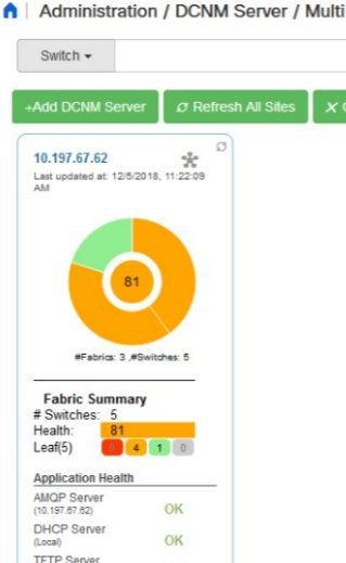
The currently logged on DCNM application health status is displayed on the screen.
Note
The Application Health function is only available for the DCNM ISO/OVA installation type and not for the Windows/RHEL installation type.
-
Click +Add DCNM Server. The Enter Remote DCNM Server Information screen comes up.
Enter the remote DCNM server name, its IP address or URL, the user credentials of the remote DCNM server, and optionally, the port number.
Note
Do not disable the Use HTTPS check box. If you disable, DCNM will not be accessible.

-
Click OK. After validation, the remote DCNM server is represented in the screen, next to the local DCNM server.

You can click Refresh All Sites to display updated information.
Retrieve Switch Information
-
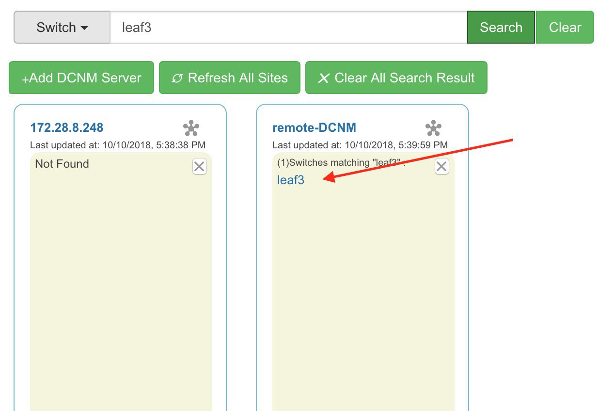
Choose Administration > DCNM Server > Multi Site Manager. The Multi Site Manager screen comes up
-
From the search box at the top of the screen, search for a switch based on one of the following parameters:
-
VM information (VM IP and VM Name fields) - A connected VM’s IP address or name.
-
Switch information (Switch and MAC fields) – A switch’s name or MAC address.
-
Segment (Segment ID field) that has presence on the switch.
If there is a match, the switch name appears as a hyperlink below the search box, in the appropriate local or remote DCNM server depiction.
In this example, the switch leaf3 is available in the remote site managed by a DCNM server. A link to leaf3 is available in the remote-DCNM panel.
-
-
Click leaf3 to view detailed switch information in an adjacent browser tab.
At any point in time, you can click the Launch Topology View icon to view the fabric’s topology.
Device Connector
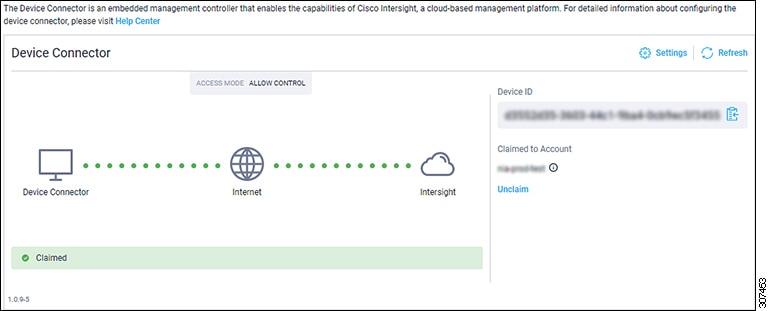
The Device Connector is an embedded management controller that enables the capabilities of Cisco Intersight, a cloud-based management platform.
Networks Insights applications are connected to the Cisco Intersight cloud portal through a Device Connector which is embedded in the management controller of the Cisco DCNM platform. Cisco Intersight is a virtual appliance that helps manage and monitor devices through the Network Insights application. The Device Connector provides a secure way for connected DCNM to send information and receive control instructions from the Cisco Intersight portal, using a secure Internet connection.
Configuring Device Connector
To configure the Device Connector from the Cisco DCNM Web UI, perform the following steps:
-
Choose Administration > DCNM Server > Device Connector.
The Device Connector work pane appears.
-
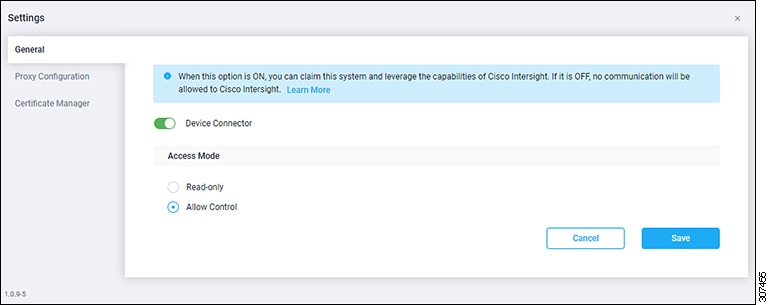
Click Settings.
The Settings - General window appears.
-
Device Connector (switch)
This is the main switch for the Device Connector communication with Cisco Intersight. When the switch is on (green highlight), the Device Connector claims the system and leverages the capabilities of the Cisco Intersight. If the switch is off (gray highlight), no communication can occur between Cisco DCNM and Cisco Intersight.
-
Access Mode
-
Read-only: This option ensures that there are no changes to this device from Intersight. For example, actions such as upgrading firmware or a profile deployment is not allowed in the Read-Only mode. However, the actions depend on the features available for a particular system.
-
Allow Control: This option (selected by default) enables you to perform full read/write operations from the appliance, based on the features available in Cisco Intersight.
-
-
-
Set the Device Connector to on (green highlight) and choose Allow Control.
-
Click Proxy Configuration.
The Settings - Proxy Configuration window appears.
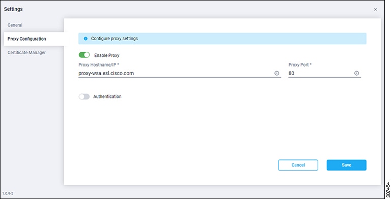
-
Enable Proxy (switch)
Enable HTTPS Proxy to configure the proxy settings.
Note
Network Insights requires Proxy settings.
-
Proxy Hostname/IP* and Proxy Port*: Enter a proxy hostname or IP address, and a proxy port number.
-
Authentication (switch)
Enable proxy access through authentication. When the switch is on (green highlight), authentication to the proxy server is required. If the switch is off (gray highlight), it does not require authentication.
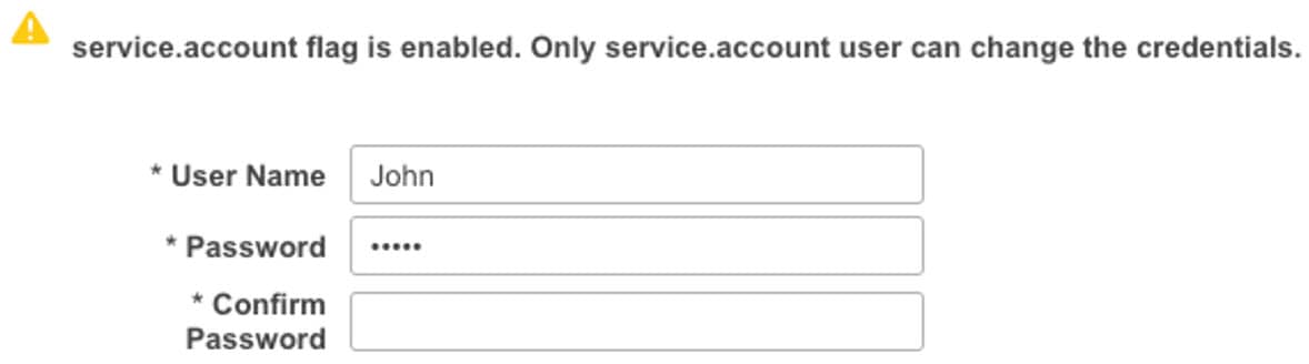
Username* and Password: Enter a user name and password for authentication.
The device connector does not mandate the format of the login credentials, they are passed as-is to the configured HTTP proxy server. The username must be a qualified domain name depending on the configuration of the HTTP proxy server.
-
-
Enable the proxy (green highlight) and enter a hostname and port number.
-
(Optional) If proxy authentication is required, enable it (green highlight) and enter a username and password.
-
Click Save.
-
Click Certificate Manager.
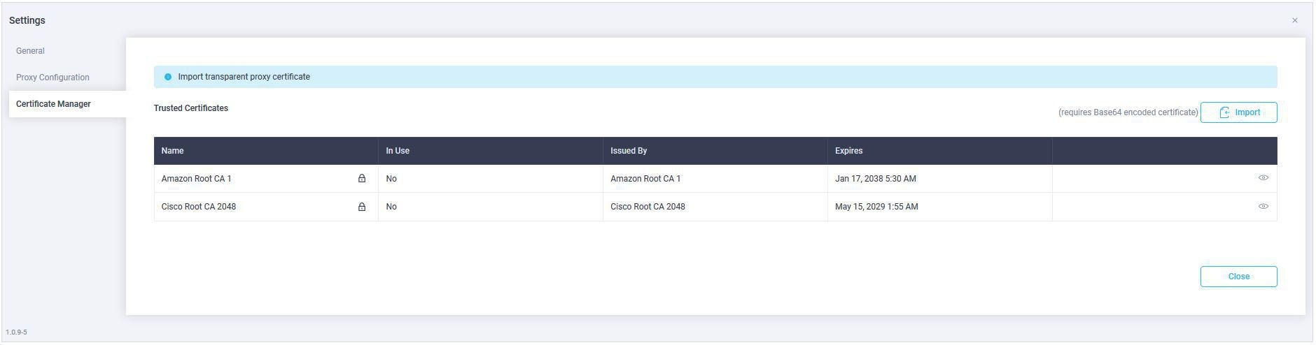
The trusted certificates appear in the table.
A list of trusted certificates appears. You can import a valid trusted certificate.
-
Import
Browse the directory, choose, and import a CA signed certificate.
Note
The imported certificate must be in the *.pem (base64encoded) format.
-
You can view the list of certificates with the following information:
-
Name—Common name of the CA certificate.
-
In Use—Whether the certificate in the trust store is used to successfully verify the remote server.
-
Issued By—The issuing authority for the certificate.
-
Expires—The expiry date of the certificate.
Note
You cannot delete bundled certificates.
-
-


 Feedback