New and Changed Information
The following table provides an overview of the significant changes up to this current release. The table does not provide an exhaustive list of all changes or of the new features up to this release.
|
Cisco APIC Release Version |
Feature |
Description |
|---|---|---|
|
Release 6.0(3) |
Ability to select new Type, Length, and Values for Azure Local. | Configuring CDP and LLDP in Leaf Switches Using the GUI |
|
Release 4.2(1i) |
Ability to configure CDP and LLDP in APIC management interface is introduced. |
-- |
Cisco Discovery Protocol
CDP is a media-independent and protocol-independent protocol that runs on all Cisco-manufactured equipment including routers, bridges, access and communication servers, and switches. CDP is a device discovery protocol that allows network management applications to automatically discover and learn about other Cisco devices that are connected to the network and/or atached to your device.
CDP gathers protocol addresses of neighboring devices and discovers the platform of those devices. CDP runs over the data link layer only. Two systems that support different Layer 3 protocols can learn about each other.
Each device that you configure for CDP sends periodic advertisements to a multicast address. Each device advertises at least one address at which it can receive SNMP messages. The advertisements also contain hold-time information, which indicates the length of time that a receiving device should hold CDP information before removing it. You can configure the advertisement or refresh timer and the hold timer.
Link Layer Discovery Protocol
To permit the discovery of non-Cisco devices, Cisco APIC supports the Link Layer Discovery Protocol (LLDP), a vendor-neutral device discovery protocol that is defined in the IEEE 802.1ab standard. LLDP allows network devices to advertise information about themselves to other devices on the network. This protocol runs over the data-link layer, which allows two systems running different network layer protocols to learn about each other.
LLDP is a one-way protocol that transmits information about the capabilities and current status of a device and its interfaces. LLDP devices use the protocol to solicit information only from other LLDP devices.
LLDP supports a set of attributes that it uses to discover other devices. These attributes contain type, length, and value (TLV) descriptions. LLDP devices can use TLVs to send and receive information to other devices on the network. Details such as configuration information, device capabilities, and device identity can be advertised using this protocol.
CDP and LLDP For Cisco APIC
Starting with Cisco APIC Release 4.2(1), you can configure Cisco Discovery Protocol (CDP) and Link Layer Discovery Protocol (LLDP) in leaf and spine switch management interfaces. The use case is that with CDP and LLDP enabled in the leaf and spine switch management interface, you can troubleshoot cabling issues without physically examining and tracking the cables. This is especially useful for sites that are unstaffed.
Users require a global, fabric-wide CDP and LLDP enabled for all the management interfaces on all the switches instead of as a switch-by-switch policy. With the availability of this feature, CDP and LLDP can be enabled or disabled for all the management interfaces at the same time.
When CDP and LLDP are enabled, the user can view the management interfaces of Cisco ACI fabric nodes as neighbors in the out-of-band (OOB) management switches used to connect to the Cisco ACI nodes. In addition, the user can detect the connected devices directly from spine switches and leaf switches.
Software Architecture
In Cisco APIC, starting with Release 4.2(1), the following LLDP and CDP policy implementations are supported for management interfaces:
-
lldp:InstPol and cdp:InstPol for switch level polices
-
lldp:IfPol and cdp:IfPol for interface level policies.
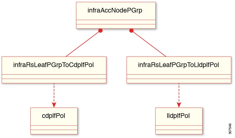
For leaf switches, two new relations are created under infraAccNodePGrp, and they are associated with the leaf switch policy group to cdpIfPol and lldpIfPol repectively. See the preceding figure for details.
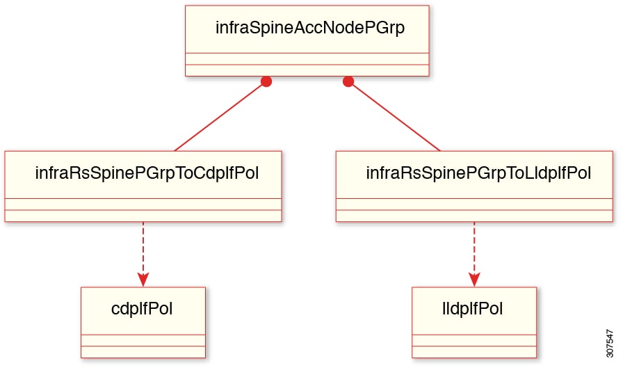
Similarly, for spine switches, two new relationships are created under infraSpineAccNodePGrp, and they are associated with the spine switch policy group to cdpIfPol and lldpIfPol repectively. See the preceding figure for details.
CDP and LLDP Guidelines and Limitations
-
CDP and LLDP must be enabled on the device before you can enable or disable it on any interfaces.
-
By default, if you do not associate any LLDP or CDP policies to a switch policy group, the protocols are disabled on the management interfaces.
-
CDP can discover up to 256 neighbors per port if the port is connected to a hub with 256 connections.
-
You can configure CDP on physical interfaces and port channels only.
-
LLDP must be enabled on the fabric before you can enable or disable it on any interfaces.
-
LLDP can discover up to one device per port.
-
Additional LLDP and IEEE DCBX TLVs are not supported on FEX interfaces.
-
The TLV name will only have the first 32 characters as specified by standards, even if the user configures more than 32 characters when creating VLANs.
-
Even if there are more than 25 active VLANs on an interface, only 25 VLANs are advertised in the VLAN name TLV.
-
The VLANs associated with a routed sub-interface are not advertised.
-
Infra-VLAN is not advertised even if infra VLAN is enabled on the interface.
Configuring CDP and LLDP in Spine Switches Using the GUI
In the following task, you create a separate CDP and LLDP policy dedicated for management interfaces, and then you add the policy to the spine switch policy group as a node level policy.
Before you begin
Procedure
|
Step 1 |
On the menu bar, choose . |
||
|
Step 2 |
Right-click and choose Create CDP Interface Policy. |
||
|
Step 3 |
In the Create CDP Interface Policy dialog box, perform the following actions: |
||
|
Step 4 |
In the Navigation pane, choose . |
||
|
Step 5 |
Right-click and choose Create LLDP Interface Policy. |
||
|
Step 6 |
In the Create LLDP Interface Policy dialog box, perform the following actions: |
||
|
Step 7 |
To apply the CDP and LLDP policies to the appropriate spine switch, create a Policy Group by navigating on the menu bar to , and right-click Create Spine Switch Policy Group. |
||
|
Step 8 |
In the Create Spine Switch Policy Group dialog box, perform the following actions:
This creates the Spine Switch Policy Group.
|
||
|
Step 9 |
To create a spine switch profile, navigate to , and right-click Profiles to choose Create Spine Profile. |
||
|
Step 10 |
In the Create Spine Profile dialog box, perform the following actions:
Your spine switch profile is created and the spine switch policy group is associated with it.
|
Configuring CDP and LLDP in Leaf Switches Using the GUI
Before you begin
Procedure
|
Step 1 |
On the menu bar, choose . |
||
|
Step 2 |
Right-click and choose Create CDP Interface Policy. |
||
|
Step 3 |
In the Create CDP Interface Policy dialog box, perform the following actions: |
||
|
Step 4 |
In the Navigation pane, choose . |
||
|
Step 5 |
Right-click and choose Create LLDP Interface Policy. |
||
|
Step 6 |
In the Create LLDP Interface Policy dialog box, perform the following actions: |
||
|
Step 7 |
To apply the CDP and LLDP policies to the appropriate leaf switch, create a Policy Group by navigating in the menu bar to , and right-click Create Access Switch Policy Group. |
||
|
Step 8 |
To configure optional LLDP parameters, navigate in the menu bar to . In the LLDP Interface Policy - Default dialog box, perform the following actions:
|
||
|
Step 9 |
In the Create Access Switch Policy Group dialog box, perform the following actions:
This creates the Access Switch Policy Group (Leaf Switch Policy Group).
|
||
|
Step 10 |
To create a leaf switch profile, in the menu bar, navigate to , and right-click Profiles to choose Create Leaf Profile. |
||
|
Step 11 |
In the Create Leaf Profile dialog box, perform the following actions:
Your leaf switch profile is created and the leaf switch policy group is associated. The leaf switch profile is associated
at the node level and not at the interface level.
|
Configuring CDP and LLDP in Leaf and Spine Switches Using the REST API
Before you begin
SUMMARY STEPS
- Specify the leaf switch selector name and node block range and associate it with the appropriate leaf switch policy group.
- Specify the spine switch selector name and node block range and associate it with the appropriate spine switch policy group.
- Configure the leaf switch policy group with the CDP and LLDP policies.
- Configure the spine switch policy group with the CDP and LLDP policies.
- Specify the attributes for the CDP and LLDP policies that are configured.
DETAILED STEPS
|
Step 1 |
Specify the leaf switch selector name and node block range and associate it with the appropriate leaf switch policy group. Example: |
|
Step 2 |
Specify the spine switch selector name and node block range and associate it with the appropriate spine switch policy group. Example: |
|
Step 3 |
Configure the leaf switch policy group with the CDP and LLDP policies. Example: |
|
Step 4 |
Configure the spine switch policy group with the CDP and LLDP policies. Example: |
|
Step 5 |
Specify the attributes for the CDP and LLDP policies that are configured. Example: |
Configuring CDP in Leaf Switches Using NX-OS CLI
SUMMARY STEPS
- configure
- mgmt-cdp name
- admin-state {enabled | disabled }
- exit
- template leaf-policygroup leaf_group_name
- mgmt-cdp name
- exit
- leaf-profile leaf_profile_name
- leaf-group leaf_group_name
- leaf leaf_group_number
- leaf-policy-group leaf_policy_group_name
- exit
DETAILED STEPS
| Command or Action | Purpose | |
|---|---|---|
|
Step 1 |
configure Example: |
Enters global configuration mode. |
|
Step 2 |
mgmt-cdp name Example: |
Defines the CDP policy. |
|
Step 3 |
admin-state {enabled | disabled } Example: |
Sets the admin state. Default is enabled. |
|
Step 4 |
exit Example: |
Returns to global configuration mode. |
|
Step 5 |
template leaf-policygroup leaf_group_name Example: |
Defines the leaf switch policy group. |
|
Step 6 |
mgmt-cdp name Example: |
Configures the relation to the CDP policy for the leaf switch policy group. |
|
Step 7 |
exit Example: |
Returns to global configuration mode. |
|
Step 8 |
leaf-profile leaf_profile_name Example: |
Configures a leaf switch profile. |
|
Step 9 |
leaf-group leaf_group_name Example: |
Specifies a group of leaf switches. |
|
Step 10 |
leaf leaf_group_number Example: |
Adds leaf switches to the leaf profile. |
|
Step 11 |
leaf-policy-group leaf_policy_group_name Example: |
Specifies the leaf policy group to be associated to the leaf switches. |
|
Step 12 |
exit Example: |
Exits command mode. |
Configuring CDP in Spine Switches in Management Interface Using NX-OS CLI
SUMMARY STEPS
- configure
- mgmt-cdp name
- admin-state {enabled | disabled }
- exit
- template spine-policygroup spine-policy-group_group_name
- mgmt-cdp name
- exit
- spine-profile spine_profile_name
- spine-group spine_group_name
- spine spine_group_number
- spine-policy-group spine_policy_group_name
- exit
DETAILED STEPS
| Command or Action | Purpose | |
|---|---|---|
|
Step 1 |
configure Example: |
Enters global configuration mode. |
|
Step 2 |
mgmt-cdp name Example: |
Defines the CDP policy. |
|
Step 3 |
admin-state {enabled | disabled } Example: |
Sets the admin state. Default is enabled. |
|
Step 4 |
exit Example: |
Returns to global configuration mode. |
|
Step 5 |
template spine-policygroup spine-policy-group_group_name Example: |
Defines the spine switch policy group. |
|
Step 6 |
mgmt-cdp name Example: |
Configures the relation to the CDP policy for the spine switch policy group. |
|
Step 7 |
exit Example: |
Returns to global configuration mode. |
|
Step 8 |
spine-profile spine_profile_name Example: |
Configures a spine switch profile. |
|
Step 9 |
spine-group spine_group_name Example: |
Specifies a group of spine switches. |
|
Step 10 |
spine spine_group_number Example: |
Adds spine switches to the spine profile. |
|
Step 11 |
spine-policy-group spine_policy_group_name Example: |
Specifies the spine policy group to be associated to the spine switches. |
|
Step 12 |
exit Example: |
Exits command mode. |
Configuring LLDP in Leaf Switches Using NX-OS CLI
SUMMARY STEPS
- configure
- mgmt-lldp name
- admin-rx-state {enabled | disabled }
- admin-tx-state {enabled | disabled }
- exit
- template leaf-policy-group leaf_group_name
- mgmt-lldp name
- (Optional)lldp tlv-select show lldp tlv-select
- exit
- leaf-profile leaf_profile_name
- leaf-group leaf_group_name
- leaf leaf_group_number
- leaf-policy-group leaf_policy_group_name
- exit
DETAILED STEPS
| Command or Action | Purpose | |
|---|---|---|
|
Step 1 |
configure Example: |
Enters global configuration mode. |
|
Step 2 |
mgmt-lldp name Example: |
Defines the LLDP policy. |
|
Step 3 |
admin-rx-state {enabled | disabled } Example: |
Sets the admin RX state. Default is enabled. |
|
Step 4 |
admin-tx-state {enabled | disabled } Example: |
Sets the admin TX state. Default is enabled. |
|
Step 5 |
exit Example: |
Returns to global configuration mode. |
|
Step 6 |
template leaf-policy-group leaf_group_name Example: |
Defines the leaf switch policy group. |
|
Step 7 |
mgmt-lldp name Example: |
Configures the relation to the LLDP policy for the leaf switch policy group. |
|
Step 8 |
(Optional)lldp tlv-select show lldp tlv-select Example: |
Specifies the TLVs to send and receive in LLDP packets. The available TLVs are non-configurable default TLVs and the configurable optional TLVs are disabled by default. The available TLVs are dcbxp, management-address, port-description, port-vlan, system-capabilities, system-description, system-name, dcbxp max-framesize, vlan-name, and link-aggregation. |
|
Step 9 |
exit Example: |
Returns to global configuration mode. |
|
Step 10 |
leaf-profile leaf_profile_name Example: |
Configures a leaf switch profile. |
|
Step 11 |
leaf-group leaf_group_name Example: |
Specifies a group of leaf switches. |
|
Step 12 |
leaf leaf_group_number Example: |
Adds leaf switches to the leaf profile. |
|
Step 13 |
leaf-policy-group leaf_policy_group_name Example: |
Specifies the leaf policy group to be associated to the leaf switches. |
|
Step 14 |
exit Example: |
Exits command mode. |
Configuring LLDP in Spine Switches Using NX-OS CLI
SUMMARY STEPS
- configure
- mgmt-lldp name
- admin-rx-state {enabled | disabled }
- admin-tx-state {enabled | disabled }
- exit
- template spine-policy-group spine_group_name
- mgmt-lldp name
- exit
- spine-profile spine_profile_name
- spine-group spine_group_name
- spine spine_group_number
- spine-policy-group spine_policy_group_name
- exit
DETAILED STEPS
| Command or Action | Purpose | |
|---|---|---|
|
Step 1 |
configure Example: |
Enters global configuration mode. |
|
Step 2 |
mgmt-lldp name Example: |
Defines the LLDP policy. |
|
Step 3 |
admin-rx-state {enabled | disabled } Example: |
Sets the admin RX state. Default is enabled. |
|
Step 4 |
admin-tx-state {enabled | disabled } Example: |
Sets the admin TX state. Default is enabled. |
|
Step 5 |
exit Example: |
Returns to global configuration mode. |
|
Step 6 |
template spine-policy-group spine_group_name Example: |
Defines the spine switch policy group. |
|
Step 7 |
mgmt-lldp name Example: |
Configures the relation to the LLDP policy for the spine switch policy group. |
|
Step 8 |
exit Example: |
Returns to global configuration mode. |
|
Step 9 |
spine-profile spine_profile_name Example: |
Configures a spine switch profile. |
|
Step 10 |
spine-group spine_group_name Example: |
Specifies a group of spine switches. |
|
Step 11 |
spine spine_group_number Example: |
Adds spine switches to the spine profile. |
|
Step 12 |
spine-policy-group spine_policy_group_name Example: |
Specifies the spine policy group to be associated to the spine switches. |
|
Step 13 |
exit Example: |
Exits command mode. |
 Feedback