Power Supply Installation
This section describes how to remove and install a new or replacement power supply. Your switch ships with at least one installed power supply module (AC or DC, depending on your order). The power supply modules are field-replaceable units (FRUs) and are hot-swappable.
For translations of the safety warnings in this chapter, see the Regulatory Compliance and Safety Information for the Cisco CGS 2520 on the documentation CD and also on Cisco.com.
■![]() Installing the Power Supply Module in the Switch
Installing the Power Supply Module in the Switch
■![]() Removing the Power Supply Module
Removing the Power Supply Module
Power Supply Modules
For information on the power supply modules, see Power Supply Features.
|
|
|
|---|---|
| Low-voltage DC. For voltage information, see Table 19. |
|
| High-voltage AC or DC. For voltage information, see Table 18. |
|
| (For China) High-voltage AC or DC. For voltage information, see Table 18. |
Note: Each power supply module can support an equivalent PoE load of two PoE+ ports or four PoE ports. When both power supply modules are installed, the system has enough power to support four PoE+ ports, or eight PoE ports. If ports are designated as high priority and low priority PoE or PoE+ ports at the command line interface (CLI), and one power supply module fails or is removed, power to the high priority ports is maintained, and power to the low priority ports is dropped. When assigning priority to PoE or PoE+ ports, it is important to assign priorities on the basis of power supply capacity.
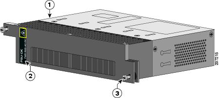
Figure 36 PWR-RGD-AC-DC Power Supply Module
|
|
|
||
|
|
|
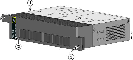
Figure 37 PWR-RGD-LOW-DC Power Supply Module
|
|
|
||
|
|
|
For a description of the PSU OK LEDs, see Power Supply Module LEDs.
Power Supply Module Installation
■![]() Installing a Power Supply Module
Installing a Power Supply Module
■![]() Removing the Power Supply Module
Removing the Power Supply Module
Installation Guidelines
Observe these guidelines when removing or installing a power supply module:
A power supply module that is only partially connected to the switch disrupts the system operation.
Warning: Blank faceplates and cover panels serve three important functions: they prevent exposure to hazardous voltages and currents inside the chassis; they contain electromagnetic interference (EMI) that might disrupt other equipment; and they direct the flow of cooling air through the chassis. Do not operate the system unless all cards, faceplates, front covers, and rear covers are in place.
Statement 1029
Note: You can order the blank cover (part number RPS-CG-COVER=).
Warning: Do not reach into a vacant slot while installing or removing a module. Exposed circuitry is an energy hazard. Statement 206
Warning: Only trained and qualified personnel should be allowed to install, replace, or service this equipment. Statement 1030
Warning: Do not work on the system or connect or disconnect cables during periods of lightning activity. Statement 1001
Installing a Power Supply Module
This procedure is for installing a power supply module in the PSU1 or PSU2 slot.
Warning: The covers are an integral part of the safety design of the product. Do not operate the unit without the covers installed. Statement 1077
Warning: This unit might have more than one power supply connection. All connections must be removed to de-energize the unit. Statement 1028
Caution: Equipment installation must comply with local and national electrical codes.
Equipment That You Need
■![]() Ratcheting torque flathead screwdriver that exerts up to 15-inch pound (in-lb) of torque
Ratcheting torque flathead screwdriver that exerts up to 15-inch pound (in-lb) of torque
■![]() Ring, spade, or flanged spade terminal
Ring, spade, or flanged spade terminal
–![]() Ring terminal (such as Tyco part number 2-34158-1 for 16 – 14 AWG or 2-34852-1 for 12 – 10 AWG wire)
Ring terminal (such as Tyco part number 2-34158-1 for 16 – 14 AWG or 2-34852-1 for 12 – 10 AWG wire)
–![]() Spade terminal (such as Tyco part number 54367-2 for 16 – 14 AWG wire)
Spade terminal (such as Tyco part number 54367-2 for 16 – 14 AWG wire)
–![]() Flanged spade terminal (such as Tyco part number 2-324165-1 for 16 – 14 AWG wire or 1-324581-1 for 12 – 10 AWG wire)
Flanged spade terminal (such as Tyco part number 2-324165-1 for 16 – 14 AWG wire or 1-324581-1 for 12 – 10 AWG wire)
–![]() Use the 16-14 AWG wire and appropriate terminals for the AC or high-voltage DC power supply
Use the 16-14 AWG wire and appropriate terminals for the AC or high-voltage DC power supply
–![]() Use the12-10 AWG wire and appropriate terminals for the low-voltage DC power supply
Use the12-10 AWG wire and appropriate terminals for the low-voltage DC power supply
■![]() Crimping tool (such as Thomas & Bett part number WT2000, ERG-2001)
Crimping tool (such as Thomas & Bett part number WT2000, ERG-2001)
■![]() 6-gauge copper ground wire (such as Belden part number 9906)
6-gauge copper ground wire (such as Belden part number 9906)
■![]() 12-AWG wire (minimum) for the low-voltage power supply module and 16-AWG (minimum) wire for the high-voltage power supply module
12-AWG wire (minimum) for the low-voltage power supply module and 16-AWG (minimum) wire for the high-voltage power supply module
■![]() For power source connections, use wires rated for at least 194°F (90°C).
For power source connections, use wires rated for at least 194°F (90°C).
■![]() UL- and CSA-rated style 1007 or 1569 twisted-pair copper wire (such as Belden part number 9318)
UL- and CSA-rated style 1007 or 1569 twisted-pair copper wire (such as Belden part number 9318)
■![]() Wire-stripping tools for stripping 6-, 10-, 12-, 14-, and 16-gauge wires.
Wire-stripping tools for stripping 6-, 10-, 12-, 14-, and 16-gauge wires.
Grounding the Switch
Follow the grounding procedures at your site and observe these warnings:
Warning: This equipment must be grounded. Never defeat the ground conductor or operate the equipment in the absence of a suitably installed ground conductor. Contact the appropriate electrical inspection authority or an electrician if you are uncertain that suitable grounding is available. Statement 1024
Warning: When installing or replacing the unit, the ground connection must always be made first and disconnected last. Statement 1046
Caution: Follow the grounding procedure instructions, and use a UL-listed lug (included with the switch) for number-6 AWG wire and 10-32 ground-lug screws.
Note: You can use the grounding lug to attach a wrist strap for ESD protection during servicing.
Note: Follow the grounding requirements for your site.
To install a dual-hole lug on the switch:
1.![]() Use a Phillips screwdriver or a ratcheting torque screwdriver with a Phillips head to remove the ground screw from the cable side of the switch.
Use a Phillips screwdriver or a ratcheting torque screwdriver with a Phillips head to remove the ground screw from the cable side of the switch.
2.![]() Strip the 6-gauge ground wire to 0.5 inch (12.7 mm) ± 0.02 inch (0.5 mm) (see Figure 38).
Strip the 6-gauge ground wire to 0.5 inch (12.7 mm) ± 0.02 inch (0.5 mm) (see Figure 38).
Note: Stripping more than the recommended amount of wire can leave exposed wire from the connector.
Figure 38 Stripping the Ground Wire
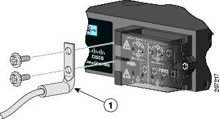
3.![]() Insert the ground wire into the terminal lug, and crimp the terminal to the wire (see Figure 39).
Insert the ground wire into the terminal lug, and crimp the terminal to the wire (see Figure 39).
Figure 39 Crimping the Terminal Lug
4.![]() Slide the ground screw from Step 1 through the terminal lug.
Slide the ground screw from Step 1 through the terminal lug.
5.![]() Insert the ground screws into the opening on the cable side.
Insert the ground screws into the opening on the cable side.
Figure 40 Attaching the Terminal Lug
|
|
6.![]() Use a ratcheting torque screwdriver to tighten the ground screws to 30 in-lb (± 2 in-lb).
Use a ratcheting torque screwdriver to tighten the ground screws to 30 in-lb (± 2 in-lb).
7.![]() Attach the other end of the ground wire to a grounded bare metal surface, such as a ground bus or a grounded bare rack.
Attach the other end of the ground wire to a grounded bare metal surface, such as a ground bus or a grounded bare rack.
Installing the Power Supply Module in the Switch
1.![]() Ensure that the power is off at the AC or DC circuits.
Ensure that the power is off at the AC or DC circuits.
Locate the circuit breakers, turn them OFF, and tape them in the OFF position.
Note: If the power is not off at the AC or DC circuit breaker, do not touch the power-input terminal.
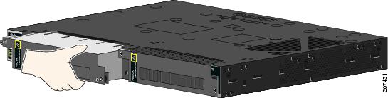
2.![]() Use a Phillips screwdriver to loosen the two captive screws of the blank power supply module and gently pull it out. See Figure 41 and Figure 42.
Use a Phillips screwdriver to loosen the two captive screws of the blank power supply module and gently pull it out. See Figure 41 and Figure 42.
Figure 41 Loosen the Screws on the Power Supply Blank
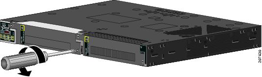
Figure 42 Remove the Power Supply Blank
3.![]() Insert the power supply module into the slot, and gently push it in (see Figure 43).
Insert the power supply module into the slot, and gently push it in (see Figure 43).
Note: Ensure that the power supply module is flush with the switch.
Figure 43 Insert the Power Supply Module
4.![]() Use a ratcheting torque screwdriver to torque each screw to 8–10 in-lb.
Use a ratcheting torque screwdriver to torque each screw to 8–10 in-lb.
Wiring the Power Source
Before you wire the power source, review the warnings in this section:
Warning: This product relies on the building’s installation for short-circuit (overcurrent) protection. Ensure that the protective device is rated not greater than:
AC: 5 A, DC: 15 A Statement 1005
Warning: A readily accessible two-poled disconnect device must be incorporated in the fixed wiring.
Statement 1022
Warning: Only trained and qualified personnel should be allowed to install or replace this equipment.
Statement 1030
Warning: Hazardous voltage or energy may be present on power terminals. Always replace cover when terminals are not in service. Be sure uninsulated conductors are not accessible when cover is in place. Statement 1086
1.![]() Ensure that the power is off at the AC or DC circuits.
Ensure that the power is off at the AC or DC circuits.
Locate the circuit breakers, turn them OFF, and tape them in the OFF position.
Note: Do not connect the switch to a power source that has an ON/OFF switch.
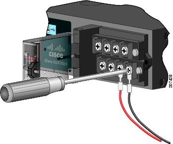
2.![]() Use a Phillips screwdriver to loosen the captive screw on the power-input terminal, and open the cover.
Use a Phillips screwdriver to loosen the captive screw on the power-input terminal, and open the cover.
Figure 44 Opening the Power-Input Terminal Cover
The terminal screws labels are on the power-input terminal cover (see Figure 45).
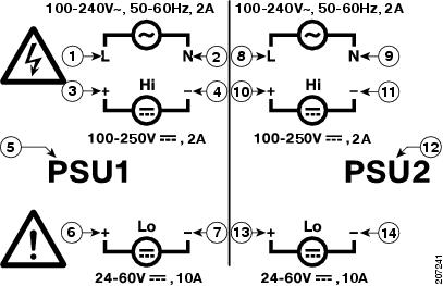
Figure 45 Power-Input Terminal
|
|
|
||
|
|
|
||
|
|
|
||
|
|
|
||
|
|
|
||
|
|
|
||
|
|
|
Note: The power supply module 1 connection is labeled PSU1, and the power supply module 2 connection is labeled PSU2. Make sure that you connect the wires to the correct terminal screws.
3.![]() Use twisted-pair copper wire (14- to 18-AWG) to connect from the power-input terminal to the power source.
Use twisted-pair copper wire (14- to 18-AWG) to connect from the power-input terminal to the power source.
Note: Use 12-AWG (minimum) for the low-voltage DC power supply module. Use 16-AWG (minimum) for the high-voltage AC or DC power supply module.
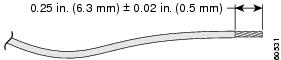
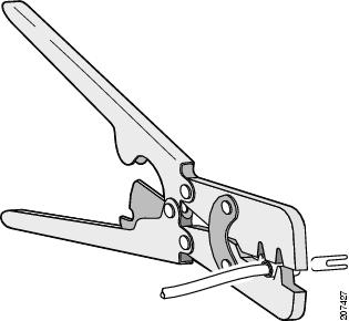
4.![]() Strip each of the two wires to 0.25 inch (6.3 mm) ± 0.02 inch (0.5 mm).
Strip each of the two wires to 0.25 inch (6.3 mm) ± 0.02 inch (0.5 mm).
Note: Do not strip more than 0.27 inch (6.8 mm) of insulation from the wire. Stripping more than the recommended amount of wire can leave exposed wire from the connector after installation.
Figure 46 Stripping the Input Power Source Wire
5.![]() Insert the wire into a spade terminal, and crimp the it to the wire.
Insert the wire into a spade terminal, and crimp the it to the wire.
You can also use a ring or flanged spade terminal as listed in the Equipment That You Need.
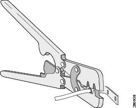
Figure 47 Crimping the Spade Terminal Lug
6.![]() Loosen the terminal screw, and slide the terminal under the screw and washer (see Figure 49).
Loosen the terminal screw, and slide the terminal under the screw and washer (see Figure 49).
Note: Use the appropriate terminal screws, depending on whether you are installing a high-voltage (AC or DC) or a low-voltage (DC) power supply.
–![]() Connect the line wire into the terminal screw labeled L and the neutral wire into the terminal screw labeled N to complete the AC connection.
Connect the line wire into the terminal screw labeled L and the neutral wire into the terminal screw labeled N to complete the AC connection.
Figure 48 Connecting the Wires to the High-Voltage AC Power (PSU1)
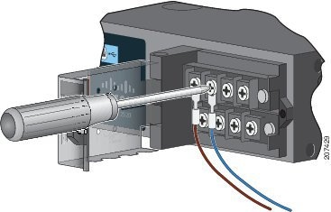
–![]() Connect the positive wire into the terminal screw labeled “ +”, and the negative wire into the terminal screw labeled “ – ”.
Connect the positive wire into the terminal screw labeled “ +”, and the negative wire into the terminal screw labeled “ – ”.
Low-voltage DC Power-Supply Module
–![]() Connect the wires to the terminals labeled Lo.
Connect the wires to the terminals labeled Lo.
High-voltage DC Power-Supply Module
–![]() Connect the wires to the terminals labeled Hi.
Connect the wires to the terminals labeled Hi.
Note: Ensure that you cannot see any wire lead. Only wire with insulation should extend from the terminal screw.
Figure 49 Connecting the Wires to the Low-Voltage DC Power (PSU2)
8.![]() Torque the captive screws (above the wires) to 8.5 in-lb (± 0.5 in-lb).
Torque the captive screws (above the wires) to 8.5 in-lb (± 0.5 in-lb).
9.![]() Complete the power connection:
Complete the power connection:
–![]() Connect the other end of the line wire (the one connected to L) to the line terminal on the AC-power source, and connect the other end of the neutral wire (the one connected to N) to the neutral terminal on the AC power source.
Connect the other end of the line wire (the one connected to L) to the line terminal on the AC-power source, and connect the other end of the neutral wire (the one connected to N) to the neutral terminal on the AC power source.
–![]() Connect the other end of the positive wire (the one connected to +) to the positive terminal on the DC-power source, and connect the other end of the negative wire (the one connected
Connect the other end of the positive wire (the one connected to +) to the positive terminal on the DC-power source, and connect the other end of the negative wire (the one connected
to –) to the negative terminal on the DC power source.
Note: Ensure that you cannot see any wire lead. Only wire with insulation should extend from the terminal screw.
10.![]() If you have two power supplies, repeat steps 1 through 10.
If you have two power supplies, repeat steps 1 through 10.
11.![]() Close the power-input terminal cover.
Close the power-input terminal cover.
12.![]() Use a ratcheting torque screwdriver to torque the screw to 6–8 in-lb.
Use a ratcheting torque screwdriver to torque the screw to 6–8 in-lb.
13.![]() Turn on the power at the AC or DC circuit, verify that the PSU1 or PSU2 LED on the switch and PSU OK LED on the power supply module are green.
Turn on the power at the AC or DC circuit, verify that the PSU1 or PSU2 LED on the switch and PSU OK LED on the power supply module are green.
See the switch software guide for information on how to configure the power supply settings.
Removing the Power Supply Module
The power supply modules are hot-swappable. By removing the power supply modules, you can power off the switch without disconnect the wiring from the power-input terminal.
1.![]() Ensure that the power is off at the AC or DC circuits.
Ensure that the power is off at the AC or DC circuits.
Locate the circuit breakers, turn them OFF, and tape them in the OFF position.
Warning: If the power is not off at the AC or DC circuit breaker, do not touch the power-input terminal.
2.![]() Verify that the PSU LED and PSU OK LED is blinking red or is off.
Verify that the PSU LED and PSU OK LED is blinking red or is off.
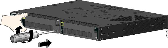
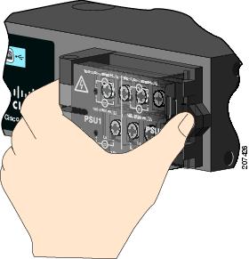
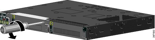
3.![]() Use a Phillips screwdriver to loosen the captive screws that secure the power supply module to the switch (see Figure 50).
Use a Phillips screwdriver to loosen the captive screws that secure the power supply module to the switch (see Figure 50).
Warning: Hot surface. Statement 1079
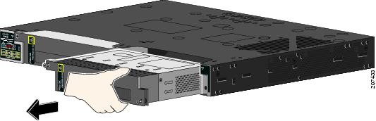
4.![]() Remove the power supply module from the power slot.
Remove the power supply module from the power slot.
The power supply module might be hot (see Figure 51).
5.![]() Install a new power supply module or a blank cover.
Install a new power supply module or a blank cover.
Figure 51 Removing the Power Supply Module
Caution: To prevent exposure to hazardous voltages and to contain electromagnetic interference (EMI), either a power supply module or a blank cover must be in each power supply module slot at all times. You can order the blank cover (part number RPS-CG-COVER=).
 Feedback