Switch Installation
This chapter contains the steps to install the switch. Please read the topics and follow the steps in the following order:
Warnings
These warnings are translated into several languages in the Regulatory Compliance and Safety Information for the Cisco CGS 2520 document that ships on the documentation CD.
These warning statements apply to all the switches:

Warning![]() Before working on equipment that is connected to power lines, remove jewelry (including rings, necklaces, and watches). Metal objects will heat up when connected to power and ground and can cause serious burns or weld the metal object to the terminals. Statement 43
Before working on equipment that is connected to power lines, remove jewelry (including rings, necklaces, and watches). Metal objects will heat up when connected to power and ground and can cause serious burns or weld the metal object to the terminals. Statement 43
Warning![]() Do not work on the system or connect or disconnect cables during periods of lightning activity. Statement 1001
Do not work on the system or connect or disconnect cables during periods of lightning activity. Statement 1001
Warning![]() Read the installation instructions before you connect the system to its power source. Statement 1004
Read the installation instructions before you connect the system to its power source. Statement 1004
Warning![]() This unit is intended for installation in restricted access areas. A restricted access area can be accessed only through the use of a special tool, lock and key, or other means of security. Statement 1017
This unit is intended for installation in restricted access areas. A restricted access area can be accessed only through the use of a special tool, lock and key, or other means of security. Statement 1017
Warning![]() This equipment must be grounded. Never defeat the ground conductor or operate the equipment in the absence of a suitably installed ground conductor. Contact the appropriate electrical inspection authority or an electrician if you are uncertain that suitable grounding is available. Statement 1024
This equipment must be grounded. Never defeat the ground conductor or operate the equipment in the absence of a suitably installed ground conductor. Contact the appropriate electrical inspection authority or an electrician if you are uncertain that suitable grounding is available. Statement 1024
Warning![]() This unit might have more than one power supply connection. All connections must be removed to de-energize the unit. Statement 1028
This unit might have more than one power supply connection. All connections must be removed to de-energize the unit. Statement 1028
Warning![]() Only trained and qualified personnel should be allowed to install, replace, or service this equipment. Statement 1030
Only trained and qualified personnel should be allowed to install, replace, or service this equipment. Statement 1030
Warning![]() Ultimate disposal of this product should be handled according to all national laws and regulations. Statement 1040
Ultimate disposal of this product should be handled according to all national laws and regulations. Statement 1040
Warning![]() For connections outside the building where the equipment is installed, the following ports must be connected through an approved network termination unit with integral circuit protection.
For connections outside the building where the equipment is installed, the following ports must be connected through an approved network termination unit with integral circuit protection.
10/100/1000 Ethernet Statement 1044
Warning![]() To prevent the system from overheating, do not operate it in an area that exceeds the maximum recommended ambient temperature of:
To prevent the system from overheating, do not operate it in an area that exceeds the maximum recommended ambient temperature of:
140°F (60°C) Statement 1047
Warning![]() This equipment is supplied as “open type” equipment. It must be mounted within an enclosure that is suitably designed for those specific environmental conditions that will be present and appropriately designed to prevent personal injury resulting from accessibility to live parts. The interior of the enclosure must be accessible only by the use of a tool. The enclosure must meet IP 54 or NEMA type 4 minimum enclosure rating standards. Statement 1063
This equipment is supplied as “open type” equipment. It must be mounted within an enclosure that is suitably designed for those specific environmental conditions that will be present and appropriately designed to prevent personal injury resulting from accessibility to live parts. The interior of the enclosure must be accessible only by the use of a tool. The enclosure must meet IP 54 or NEMA type 4 minimum enclosure rating standards. Statement 1063
Warning![]() Installation of the equipment must comply with local and national electrical codes. Statement 1074
Installation of the equipment must comply with local and national electrical codes. Statement 1074

Note![]() For U.S. installations, refer to national electrical code ANSI/NFPA 70.
For U.S. installations, refer to national electrical code ANSI/NFPA 70.
Warning![]() To prevent airflow restriction, allow clearance around the ventilation openings to be at least:
To prevent airflow restriction, allow clearance around the ventilation openings to be at least:
1.75 in. (4.4 cm). Statement 1076
Installation Guidelines
Before installing the switch, verify that these guidelines are met:
- Cabling must be kept away from sources of electrical noise, such as radios, power lines, and fluorescent lighting fixtures. Make sure that the cabling is away from other devices that might damage the cables.
- Operating environment is within the ranges listed in Technical Specifications, page A-1.
- Relative humidity around the switch does not exceed 95 percent (noncondensing).
- Altitude at the installation site is not higher than 10,000 feet.
- For 10/100 and 10/100/1000 fixed ports, cable lengths from the switch to connected devices are not more than 328 feet (100 meters).
- For cable lengths for small-form-factor pluggable (SFP)-module connections, see the SFP Module Cables, page B-4 and the module documentation.
- Airflow around the switch and through the vents is unrestricted. To prevent overheating, the switch must meet the minimum clearance of 1.75 inches (4.4 cm) at the top and bottom. For clearances needed for wall mounting, see specifications in Wall-Mounting, page 2-16.
Note![]() If the switch is installed in a closed or multirack assembly, take into consideration that the temperature around the switch might be greater than normal room temperature and that special accommodations in clearance must be made.
If the switch is installed in a closed or multirack assembly, take into consideration that the temperature around the switch might be greater than normal room temperature and that special accommodations in clearance must be made.
Verifying Switch Operation
Before installing the switch in a rack or on a wall, you should power on the switch and verify that the switch passes the power-on self-test (POST).
To wire the switch to the power source, see Power Supply Installation, page 3-1.
When the switch begins POST, the System LED blinks green, and the other LEDs stay green. When the switch passes POST, the System LED turns green. The other LEDs turn off and return to their operating status. If the switch fails POST, the System LED is amber.
Note![]() Contact Cisco Systems immediately if your switch fails POST.
Contact Cisco Systems immediately if your switch fails POST.
After a successful POST, disconnect the power from the switch. For more information, see Power Supply Installation, page 3-1 See the Installing the Switch, page 2-4 to install the switch into a rack or onto a wall.
Installing the Switch
The following installation information is covered in this section:
Note![]() After the switch is mounted onto the rack, connect the power source to the switch. See Power Supply Installation, page 3-1.
After the switch is mounted onto the rack, connect the power source to the switch. See Power Supply Installation, page 3-1.
Mounting into a Rack
The following mounting procedures are explained in this section:
- .Mounting Brackets
- Attaching Brackets for 19-Inch Racks
- Attaching Brackets for 19-Inch Racks (IP-30 Compliance)
- Attaching Brackets for 23-Inch Racks
- Attaching Brackets for ETSI Racks
- Mounting the Switch into a Rack
Warning![]() To prevent bodily injury when mounting or servicing this unit in a rack, you must take special precautions to ensure that the system remains stable. The following guidelines are provided to ensure your safety:
To prevent bodily injury when mounting or servicing this unit in a rack, you must take special precautions to ensure that the system remains stable. The following guidelines are provided to ensure your safety:
• This unit should be mounted at the bottom of the rack if it the only rack in the rack
• When mounting this unit in a partially filled rack, load the rack from the bottom to the top with the heaviest component at the bottom of the rack
• If the rack is provided with stabilizing devices, install the stabilizers before mounting or servicing the unit in the rack. Statement 1008
.Mounting Brackets
Figure 2-1 shows the 19-inch rack mounting brackets.
Figure 2-1 19-inch Mounting Brackets
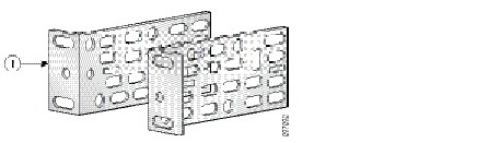
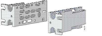
Figure 2-2 shows the 23-inch rack mounting brackets.
Figure 2-2 23-inch Mounting Brackets
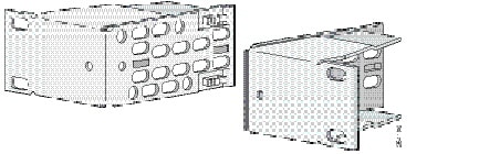
Figure 2-3 shows the ETSI rack mounting brackets.
Figure 2-3 ETSI Mounting Brackets
Attaching Brackets for 19-Inch Racks
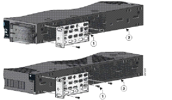
Figure 2-4 and Figure 2-5 shows the 19-inch rack mounting bracket locations on the switch for cable-side mounting and power-side mounting onto an 19-inch rack.
Figure 2-4 Attaching Brackets for 19-Inch Racks
|
|
|
||
|
|
|
Figure 2-5 Attaching Brackets for 19-Inch Racks
|
|
|
||
|
|
|
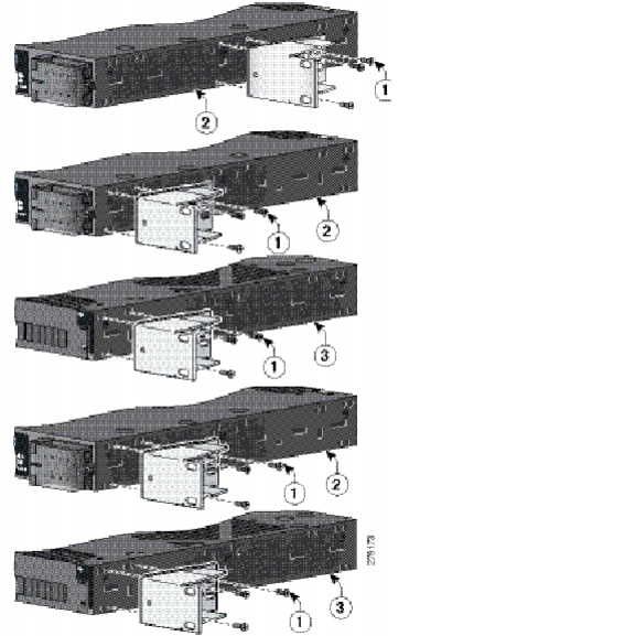
Attaching Brackets for 19-Inch Racks (IP-30 Compliance)
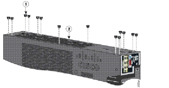
Before installing the mounting brackets, you need to install the rubber plugs into the unused mounting holes of the switch chassis. You can get the appropriate rubber plugs by ordering kit CGS-2520-IP30KIT.
Follow the procedure below to install the rubber plugs.
Step 1![]() Determine whether you will install using the mid-mount, cable-side, or power supply-side positioning by identifying your bracket mounting positions shown in Figure 2-9 and Figure 2-10.
Determine whether you will install using the mid-mount, cable-side, or power supply-side positioning by identifying your bracket mounting positions shown in Figure 2-9 and Figure 2-10.
Step 2![]() Insert the rubber plugs into the appropriate holes according to your mount position as shown in Figure 2-6 and Figure 2-7. Follow the same procedure for both sides of the switch.
Insert the rubber plugs into the appropriate holes according to your mount position as shown in Figure 2-6 and Figure 2-7. Follow the same procedure for both sides of the switch.
Figure 2-6 Inserting the Rubber Plugs
|
|
|
||
|
|
|
Figure 2-7 Inserting the Rubber Plugs
|
|
|
||
|
|
|
Step 3![]() Use a screwdriver or pen to completely push in the rubber plugs. Figure 2-8 shows a close-up of the rubber plug and how they are inserted into the mounting holes.
Use a screwdriver or pen to completely push in the rubber plugs. Figure 2-8 shows a close-up of the rubber plug and how they are inserted into the mounting holes.
Figure 2-8 Inserting the Rubber Plugs (detail)
|
|
|
||
|
|
|
Step 4![]() Install the brackets on both sides of the switch as shown in Figure 2-9 and Figure 2-10.
Install the brackets on both sides of the switch as shown in Figure 2-9 and Figure 2-10.
Figure 2-9 Attaching Brackets for 19-Inch Racks
|
|
|
||
|
|
|
Figure 2-10 Attaching Brackets for 19-Inch Racks
|
|
|
||
|
|
|
Note For IP-30 compliance: If you use 23-inch brackets or ETSI brackets, you can insert the rubber plugs in the same holes as shown in Figure 2-6 and Figure 2-7 before installing the brackets.
Attaching Brackets for 23-Inch Racks
Figure 2-11 shows the 23-inch rack mounting bracket locations on the switch for cable-side mounting and power-side mounting onto a 23-inch rack.
Figure 2-11 Attaching Brackets for 23-Inch Racks
|
|
|
||
|
|
|
Note![]() For IP-30 compliance: If you use 23-inch brackets, you can insert the rubber plugs in the same holes as shown in Figure 2-7 or Figure 2-8 before installing the brackets.
For IP-30 compliance: If you use 23-inch brackets, you can insert the rubber plugs in the same holes as shown in Figure 2-7 or Figure 2-8 before installing the brackets.
Attaching Brackets for ETSI Racks
Figure 2-12 shows the mounting bracket locations on the switch for cable-side mounting and power-side mounting onto an ETSI rack.
Figure 2-12 Attaching Brackets for ETSI Racks

|
|
|
||
|
|
|
Note![]() For IP-30 compliance: If you use ETSI brackets, you can insert the rubber plugs in the same holes as shown in Figure 2-7 or Figure 2-8 before installing the brackets.
For IP-30 compliance: If you use ETSI brackets, you can insert the rubber plugs in the same holes as shown in Figure 2-7 or Figure 2-8 before installing the brackets.
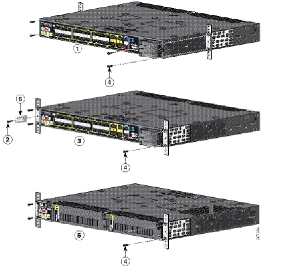
Mounting the Switch into a Rack
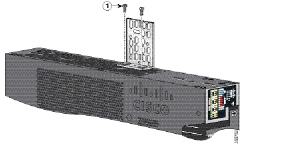
After you attach the brackets onto the switch, use the four supplied number-12 Phillips machine screws to attach the brackets to the rack as shown in Figure 2-13. (Brackets for the 19-inch rack shown in this example.)
Note![]() We recommend attaching the cable guide to prevent the cables from obscuring the LED panels on the devices in the rack. Use the supplied black screw shown in Figure 2-13 [6] to attach the cable guide to the left or right bracket.
We recommend attaching the cable guide to prevent the cables from obscuring the LED panels on the devices in the rack. Use the supplied black screw shown in Figure 2-13 [6] to attach the cable guide to the left or right bracket.
|
|
|
||
|
|
|
||
|
|
|
Wall-Mounting
The following steps are covered in this section:
Warning![]() If the switch is wall-mounted in an enclosure allow for these minimum clearances:
If the switch is wall-mounted in an enclosure allow for these minimum clearances:
• Sides of switch (facing up and facing down): 3.75 in. (9.52 cm)
• Port side 3.0 in. (7.62 cm)
• Power supply side: 5.25 in. (13.33 cm)
• Cover side (side not facing wall): 1.75 in. (4.44 cm)
• Base side (facing wall): 0 in. (0 cm)
Attaching Brackets for Wall Mounting
Follow these steps to mount the switch onto a wall.
Step 1![]() Insert the rubber plugs into the appropriate holes. Follow the same procedure for the other side of the switch.
Insert the rubber plugs into the appropriate holes. Follow the same procedure for the other side of the switch.
Step 2![]() Use a screwdriver or pen to completely push in the rubber plugs (see Figure 2-8).
Use a screwdriver or pen to completely push in the rubber plugs (see Figure 2-8).
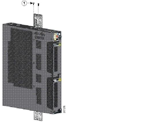
Step 3![]() Install the brackets onto both sides of the switch (see Figure 2-16).
Install the brackets onto both sides of the switch (see Figure 2-16).
Step 4![]() Secure the bracket and switch to the wall using the screws provided.
Secure the bracket and switch to the wall using the screws provided.
Figure 2-14 shows how to wall-mount the switch onto a wall.
Figure 2-14 Attaching 19-inch Rack Brackets for Wall Mounting
|
|
Wall-Mounting (for IP-30 Compliance)
Follow these steps to mount the switch onto a wall and conform to IP-30 Compliance regulations.
Step 1![]() Insert the rubber plugs into the appropriate holes (see Figure 2-15). Follow the same procedure for the other side of the switch.
Insert the rubber plugs into the appropriate holes (see Figure 2-15). Follow the same procedure for the other side of the switch.
Step 2![]() Use a screwdriver or pen to completely push in the rubber plugs (see Figure 2-8).
Use a screwdriver or pen to completely push in the rubber plugs (see Figure 2-8).
Figure 2-15 Inserting the Rubber Plugs into the Switch Holes
|
|
Step 3![]() Install the brackets on both sides of the switch (see Figure 2-16).
Install the brackets on both sides of the switch (see Figure 2-16).
Figure 2-16 Attaching 19-inch Rack Brackets
|
|
Installing and Removing SFP Modules
Small-form-factor pluggable (SFP) modules provide the uplink optical interfaces, laser send (TX) and laser receive (RX).
When installing or removing SFP modules, observe these guidelines:
- Removing and installing an SFP module can shorten its useful life. Do not remove and insert any module more often than is absolutely necessary.
- To prevent ESD damage, follow your normal board and component handling procedures when connecting cables to the switch and other devices.
Warning![]() Class 1 laser product. Statement 1008
Class 1 laser product. Statement 1008

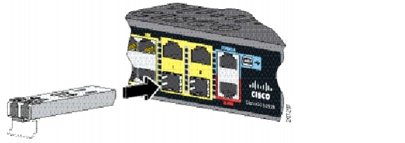
Installing SFP Modules
This section describes how to install Small Form Factor pluggable (SFP) modules. SFP modules are inserted into the SFP modules connected to the switch.
Step 1![]() Attach an ESD-preventive wrist strap to your wrist and to a bare metal surface.
Attach an ESD-preventive wrist strap to your wrist and to a bare metal surface.
Step 2![]() Find the send (TX) and receive (RX) markings on the module top.
Find the send (TX) and receive (RX) markings on the module top.
Note On some SFP modules, the send and receive (TX and RX) markings might be replaced by arrows that show the direction (send or receive) of the connection.
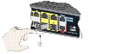
Step 3![]() If the module has a bale-clasp latch, move it to the open, unlocked position.
If the module has a bale-clasp latch, move it to the open, unlocked position.
Step 4![]() Align the module in front of the slot opening, and insert until you feel the connector snap into place.
Align the module in front of the slot opening, and insert until you feel the connector snap into place.
Step 5![]() If the module has a bale-clasp latch, close it to lock it into place.
If the module has a bale-clasp latch, close it to lock it into place.
Step 6![]() For fiber-optic SFP modules, remove the dust plugs and store them in a clean location for reuse.
For fiber-optic SFP modules, remove the dust plugs and store them in a clean location for reuse.
Step 7![]() Connect the SFP cables.
Connect the SFP cables.
Figure 2-17 Installing an SFP Module
Removing SFP Modules
This section describes how to replace small-form-factor pluggable (SFP) modules. SFP modules are inserted into the SFP modules connected to the switch.
Step 1![]() Attach an ESD-preventive wrist strap to your wrist and to a bare metal surface.
Attach an ESD-preventive wrist strap to your wrist and to a bare metal surface.
Step 2![]() Disconnect the cables from the SFP module ports. For reattachment, note which cable connector plug is send (TX) and which is receive (RX).
Disconnect the cables from the SFP module ports. For reattachment, note which cable connector plug is send (TX) and which is receive (RX).
Note On some SFP modules, the send and receive (TX and RX) markings might be replaced by arrows that show the direction (send or receive) of the connection.
Step 3![]() Insert a dust plug into the optical ports of the SFP module.
Insert a dust plug into the optical ports of the SFP module.
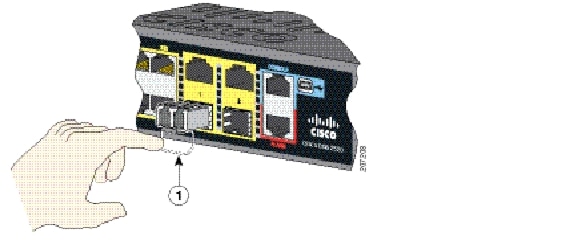
Step 4![]() If the module has a bale-clasp latch, pull the bale out and down to eject it. If the latch is obstructed and you cannot use your finger, use a small, flat-blade screwdriver or other long, narrow instrument.
If the module has a bale-clasp latch, pull the bale out and down to eject it. If the latch is obstructed and you cannot use your finger, use a small, flat-blade screwdriver or other long, narrow instrument.
Figure 2-18 Removing a Bale Clasp Latch SFP Module
Step 5![]() Grasp the SFP module, and carefully remove it from the slot.
Grasp the SFP module, and carefully remove it from the slot.
Step 6![]() Place the module in an anti-static bag or other protective environment.
Place the module in an anti-static bag or other protective environment.
Inserting and Removing the SFP Module Patch Cable
Step 1![]() Attach an ESD-preventive wrist strap to your wrist and to a bare metal surface.
Attach an ESD-preventive wrist strap to your wrist and to a bare metal surface.
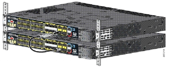
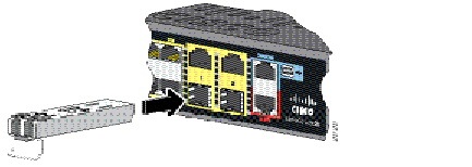
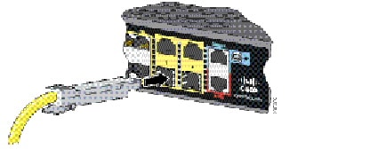
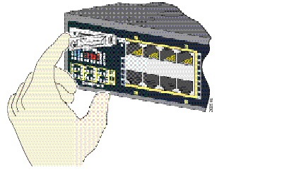
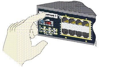
Step 2![]() Insert the SFP module patch cable into the slot until you feel the connector on the cable snap into place at the rear of the slot (see Figure 2-19).
Insert the SFP module patch cable into the slot until you feel the connector on the cable snap into place at the rear of the slot (see Figure 2-19).
Figure 2-19 Inserting an SFP Module Patch Cable
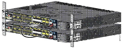
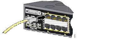
Step 3![]() Repeat these steps for the second switch that you want to connect to the first switch.
Repeat these steps for the second switch that you want to connect to the first switch.
Figure 2-20 Connecting Two Switches with an SFP Module Patch Cable
Removing the SFP Module Patch Cable
To remove an SFP module patch cable from the SFP module slot, release the connector, and pull it from the slot.
Replacing the SD Flash Memory Card
Warning![]() Be aware that the SD card contains sensitive and security relevant information, including but not limited to full device configuration information, public and private keys used for SSH and SSL (if those protocols are enabled), device passwords and others. Access to SD cards for any Cisco CGS switch should be limited to authorized personnel.
Be aware that the SD card contains sensitive and security relevant information, including but not limited to full device configuration information, public and private keys used for SSH and SSL (if those protocols are enabled), device passwords and others. Access to SD cards for any Cisco CGS switch should be limited to authorized personnel.
Step 1![]() Locate the Secure Digital (SD) flash memory card slot on the cable-side of the switch.
Locate the Secure Digital (SD) flash memory card slot on the cable-side of the switch.
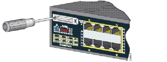
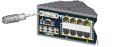
Step 2![]() Use a number 1 Phillips screwdriver to loosen the captive screw (see Figure 2-21).
Use a number 1 Phillips screwdriver to loosen the captive screw (see Figure 2-21).
Figure 2-21 Loosening the Captive Screw
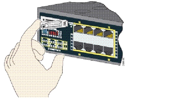
Step 3![]() Pull the cover open, and pull the cover tabs from the hinge (see Figure 2-22).
Pull the cover open, and pull the cover tabs from the hinge (see Figure 2-22).
Figure 2-22 Removing the SD Slot Cover
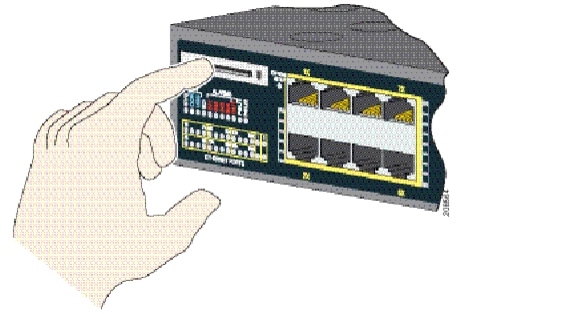
Step 4![]() Gently push the SD flash memory card to eject it (see Figure 2-23). Place it in an antistatic bag to protect it from static discharge.
Gently push the SD flash memory card to eject it (see Figure 2-23). Place it in an antistatic bag to protect it from static discharge.
Figure 2-23 Removing the SD Flash Memory Card
Step 5![]() Push the replacement card (upside down) into the slot, and press it firmly in place. The card is keyed so that you cannot insert it the wrong way.
Push the replacement card (upside down) into the slot, and press it firmly in place. The card is keyed so that you cannot insert it the wrong way.
Step 6![]() Begin replacing the cover by placing the SD slot cover tabs into the hinge.
Begin replacing the cover by placing the SD slot cover tabs into the hinge.
Step 7![]() Close the cover, and use a ratcheting torque number 1 Phillips screwdriver to torque the screw to 4.5 in-lb.
Close the cover, and use a ratcheting torque number 1 Phillips screwdriver to torque the screw to 4.5 in-lb.
|
|
|
|
|---|---|---|
|
1.100BASE-TX and 1000BASE-T traffic requires twisted four-pair, Category 5, Category 5e, or Category 6 cable. 10BASE-T traffic uses Category 3 or Category 4 cable. |
Connecting Devices to the Ethernet Ports
This section covers the following procedures:
Connecting to the 10/100 and 10/100/1000 Ports
The 10/100 and 10/100/1000 Ethernet ports use standard RJ-45 connectors with Ethernet pinouts. The maximum cable length is 328 feet (100 meters). The 100BASE-TX and 1000BASE-T traffic requires Category 5, Category 5e, or Category 6 UTP cable. The 10BASE-T traffic uses Category 3 or Category 4 cable.
The auto-negotiation feature is enabled by default on the switch. At this setting, the switch ports configure themselves to operate at the speed of the attached device. If the device does not support auto-negotiation, you can set the switch port speed and duplex parameters. To maximize performance, either let the ports autonegotiate both speed and duplex, or set the port speed and duplex parameters on both ends of the connection.
For simplified cabling, the automatic medium-dependent interface crossover (auto-MDIX) feature is enabled by default. With auto-MDIX enabled, the switch detects the required cable type for copper Ethernet connections and configures the interface accordingly. Therefore, you can use either a crossover or a straight-through cable for connections to a 10/100/1000 Ethernet port, regardless of the type of connected device.
See the switch software configuration guide or the switch command reference on Cisco.com for more information about auto-negotiation and auto-MDIX.
If auto-MDIX is disabled, use the guidelines in Table 2-1 to select the cable for connecting the 10/100/1000 Ethernet ports to other devices.
See the Connector and Cable Specifications, page B-1 for cable-pinout descriptions.
Figure 2-24 Connecting to an Ethernet Port
Connecting to the 10/100 PoE Ports
The Cisco CGS-2520-16S-8PC switch (and the CGS-2520-16S-8PC-C switch) 10/100 PoE ports have the same auto-negotiation settings and cabling requirements as those in the Connecting to the 10/100 and 10/100/1000 Ports. These ports provide PoE power.
See the PoE Ports, page 1-3 for information on the cables and connectors.
The ports provide PoE support for devices compliant with IEEE 802.3af and also provide Cisco prestandard PoE support for Cisco IP Phones and Cisco Aironet Access Points.
On a per-port basis, you can control whether or not a port automatically provides power to a connected IP phone or an access point.
To access an advanced PoE planning tool, use the Cisco Power Calculator on Cisco.com:
http://tools.cisco.com/cpc/launch.jsp
You can use this application to calculate the power supply requirements for a specific PoE configuration. The results show output current, output power, and heat dissipation.
Warning![]() Voltages that present a shock hazard may exist on Power over Ethernet (PoE) circuits if interconnections are made using uninsulated exposed metal contacts, conductors, or terminals. Avoid using such interconnection methods, unless the exposed metal parts are located within a restricted access location and users and service people who are authorized within the restricted access location are made aware of the hazard. A restricted access area can be accessed only through the use of a special tool, lock and key or other means of security. Statement 1072
Voltages that present a shock hazard may exist on Power over Ethernet (PoE) circuits if interconnections are made using uninsulated exposed metal contacts, conductors, or terminals. Avoid using such interconnection methods, unless the exposed metal parts are located within a restricted access location and users and service people who are authorized within the restricted access location are made aware of the hazard. A restricted access area can be accessed only through the use of a special tool, lock and key or other means of security. Statement 1072
Where to Go Next
After the switch is mounted onto the rack, do the following:
- Wire the switch to a power source (see Power Supply Installation, page 3-1)
- For configuration instructions about the CLI setup program, see Configuring the Switch with the CLI Setup Program, page C-1
- You can use the default configuration installed on the switch or use any of the management options described in the Management Options, page 1-13 to change the switch settings
 Feedback