User Defined Network Prescriptive Deployment Guide
Available Languages
Bias-Free Language
The documentation set for this product strives to use bias-free language. For the purposes of this documentation set, bias-free is defined as language that does not imply discrimination based on age, disability, gender, racial identity, ethnic identity, sexual orientation, socioeconomic status, and intersectionality. Exceptions may be present in the documentation due to language that is hardcoded in the user interfaces of the product software, language used based on RFP documentation, or language that is used by a referenced third-party product. Learn more about how Cisco is using Inclusive Language.
- US/Canada 800-553-2447
- Worldwide Support Phone Numbers
- All Tools
 Feedback
 Feedback
Contents
This guide is intended to provide technical guidance to design, deploy and operate Cisco User Defined Network (UDN). It focuses on the steps to enable device level segmentation for user devices such as smartphones, tablets, and media streaming devices by first restricting mDNS discovery to a user’s personal network or “room” and then optionally restricting unicast traffic between other UDNs.
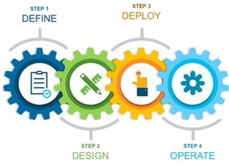
This guide contains four major sections:
The Define section defines problem being solved with Cisco UDN and provides information about how to plan for deployment, and other considerations.
The Design section discusses the interaction of the various solution components as well as providing the versions of software used in the solution.
The Deploy section provides information about various procedures to deploy the solution along with recommended practices.
The Operate section shows how to verify that the UDN components have been provisioned correctly.
When on a home network, it’s easy enough to use a streaming technology, such as Google Chromecast or Apple Airplay, to stream movies and TV shows. In a shared network environment, such as a school dormitory, it can be much harder to find your TV among all the other student’s devices. This can also cause confusion and annoyance as students can accidently stream to a device owned by a different student. This problem is not just limited to streaming to a TV but for any device using Link Local Multicast protocols.
Cisco UDN (User Defined Network) solves this problem by segmenting the user’s devices while still being on the same SSID. Users will be given their own private UDN where only devices they register will be allowed to communicate with each other. This eliminates the problem above and creates a more secure network environment.
Users will be given access to the Cisco UDN application, available on the Google Play store or Apple App store, which will be used to register the devices MAC address before arriving at the shared network environment.
| When deploying Cisco UDN, discovery and streaming is limited to registered devices within the UDN for wireless devices such as MacBooks, iPhones, and iPads. For the Apple TV, if the AirPlay settings are left in their default state, devices with Bluetooth enabled and within roughly 30 feet of the Apple TV, the signal distance for Bluetooth Low Energy (BLE), will still be able to discover and stream to an Apple TV registered within a UDN. Please refer to Appendix C for the procedure to disable AirPlay over Bluetooth if you would like to change this behavior. |
Components
Cisco UDN Mobile Application
The Cisco UDN mobile application is used for users to create and register devices to their own personal UDN. By entering their devices’ MAC addresses in the application, they register their device for use in that UDN. They can also register any streaming media players such as Apple TV or Amazon Fire TV as members of their UDN by adding their MAC addresses as well. Users may also invite guests into their UDN by sending an invite to the guest allowing them to register their device and allowing them to share devices.
The Cisco UDN Mobile Application is available for download on the Google Play Store and Apple App Store.
Cisco UDN Cloud
The Cisco UDN Cloud service serves as the communication broker between the Mobile App and the on-prem equipment required for the UDN service. The Cisco UDN Mobile App communicates with the Cisco UDN Cloud service and is used for UDN creation as well as registering mobile and other devices within the user’s UDN. The Cloud then communicates this information back to the Cisco DNA Center on the customer’s premise.
Identity Provider
The identity provider (IdP) is your organization’s SSO service used for authentication. Presently Microsoft Azure AD and SAML are supported. SAML is supported with Shibboleth or Microsoft Active Directory Federated Services (ADFS). During the user authentication to the Cisco UDN Cloud using the UDN Mobile App, your SSO service is queried and the results returned. Upon successful authentication, the user is now able to create their UDN “Room” and register devices within.
| Tech tip |
| The IdP discussed here is required for authentication and access to the Cisco UDN Cloud services. It may optionally be used but is not necessary for 802.1X network authentication to the wireless network if Active Directory or LDAP is already used as an internal identity source. |
Cisco DNA Center
At the heart of the UDN solution automation is the Cisco DNA Center. UDN is enabled with a workflow that is launched from Cisco DNA Center for establishing trust between the on-premise Cisco DNA Center appliance and the Cisco UDN Cloud services as well as provisioning, and applying UDN specific information to both the Catalyst 9800 wireless controller and Cisco ISE, both required as part of the UDN solution.
In addition to its role in the UDN solution, Cisco DNA Center can optionally centrally manage major configuration and operations workflow areas.
● Design-Configures device global settings, network site profiles for physical device inventory, DNS, DHCP, IP addressing, software image repository and management, device templates, and user access.
● Policy-Defines business intent for provisioning into the network, including creation of virtual networks, assignment of endpoints to virtual networks, policy contract definitions for groups, and configures application policies.
● Provision-Provisions devices and adds them to inventory for management, supports Cisco Plug and Play, creates fabric domains, control plane nodes, border nodes, edge nodes, fabric wireless, Cisco Unified Wireless Network wireless, transit, and external connectivity.
● Assurance-Enables proactive monitoring and insights to confirm user experience meets configured intent, using network, client, and application health dashboards, issue management, and sensor-driven testing.
● Platform-Allows programmatic access to the network and system integration with third-party systems using APIs, using feature set bundles, configurations, a runtime dashboard, and a developer toolkit.
| Tech tip |
| The Cisco UDN solution does not support fabric enabled wireless if in use as part of a Cisco SD-Access fabric. |
Cisco Identity Service Engine (ISE)
Cisco ISE allows you to provide highly secure network access to users and devices. It helps you gain visibility into what is happening in your network, such as who is connected, which applications are installed and running, and much more. It also shares vital contextual data, such as user and device identities, threats, and vulnerabilities with integrated solutions from Cisco technology partners, so you can identify, contain, and remediate threats faster.
In addition to serving as an organization’s RADIUS server for AAA, Cisco ISE inspects authentication attributes from the wireless controller to determine if the authenticating device is attempting to join a UDN enabled SSID. Once confirmed, it communicates the UDN-specific information required for UDN segmentation back to the wireless controller.
Catalyst 9800 Wireless LAN Controller
Built from the ground-up for intent-based networking and Cisco DNA, Cisco® Catalyst® 9800 Series Wireless Controllers are Cisco IOS® XE based and integrate the RF excellence of Cisco Aironet® access points, creating a best-in-class wireless experience for your evolving and growing organization. The 9800 Series is built on an open and programmable architecture with built-in security, streaming telemetry, and rich analytics.
| Tech tip |
| The Cisco UDN solution only supports the Catalyst 9800 when running in local mode, Cisco Software Defined Access (SDA) is not supported if fabric enabled wireless has been deployed. Cisco UDN is supported if the wireless in an SD-Access fabric has been deployed as over the top using local mode; both control and data plane encapsulated in CAPWAP tunnel between the access point and Catalyst 9800 wireless controller. |
Cisco Access Points
The Cisco UDN solution supports all Cisco Wave 2 access points, most notably the Cisco 1800, 2800. 3800, and 4800, as well as Cisco 9100 family of Wi-Fi 6 access points.
This section discusses the solution architecture and how the various components interact with one another. Sample flows discussing the user creation of the UDN and device registration within their room are provided. Finally, the list of components and versions of software validated in this Prescriptive Deployment Guide (PDG) are provided.
Architecture
The following information provides an overview of the UDN solution including solution automation and communication flows for user device registration and subsequent connection to the UDN enabled wireless network. It is broken into two sections including the interaction and provisioning of the solution components and the device UDN registration and subsequent attachment to the wireless network.
Solution overview
The Cisco UDN solution incorporates both Cisco Cloud and onsite components to provide segmented, personal networks in which users mobile devices and streaming entertainment devices are isolated from one another by limiting multicast advertisement of services and optionally providing unicast blocking of communications between UDNs. Cisco UDN cloud is used for UDN tenant creation, device registration, device de-registration, and UDN change/guest invite via the Cisco UDN Mobile App, The Cisco UDN on premise components include Cisco wireless networking using the Catalyst 9800 controller along with Wave 2 Cisco and Catalyst 9100 access points for network connectivity, Cisco ISE for network access control through RADIUS AAA and Cisco DNA Center for provisioning of the Cisco onsite components as well as communications with Cisco UDN Cloud for UDN specific information.
Cisco UDN Mobile App
In addition to cloud and on-premise infrastructure, the Cisco UDN Mobile App, available for both Android and iOS-based devices and downloadable from both the Google Play Store and the Apple AppStore, is used for UDN creation, device registration, and guest invitation. When first opening the application, the user will provide their credentials to gain access to the Cisco UDN service where all UDN creation and maintenance activities are performed. From the Cisco UDN Mobile App users can create their “Room” (UDN), register their mobile devices, register their multimedia devices, and invite/remove other guest devices.
Using the Cisco UDN Mobile App, users can register their devices while offsite or once they arrive on site. If the device is using MAC randomization, which is on by default on Android-based devices, off site registration will not be possible unless it is manually disabled on the device. Should it be undesirable to have the user disable MAC randomization, once on-site and attached to the UDN SSID, they will then be able to register their device.
| Tech tip |
| MAC randomization, implemented on Android devices today, will also be implemented on Apple devices beginning with iOS 14. |
Cisco UDN Cloud Service
Cisco UDN Cloud provides the services for the creation and maintenance of UDNs, As just described, the Cisco UDN mobile application is used by users to create and register devices to their own personal UDN. As users using the Cisco UDN Mobile App transparently access the Cisco UDN Cloud, it redirects the authentication requests to your single sign on (SSO service) such as Microsoft Azure AD or acts as a Security Assertion Markup Language (SAML) 2.0 Service Provider (SP) redirecting authentication requests to an Identity Provider (IdP) such as Shibboleth or Microsoft Active Directory Federated Services (ADFS).
When using Microsoft Azure AD as your IdP, it is either necessary to duplicate the user information contained in Azure AD by manual creation in Cisco UDN Cloud or you can use Group attributes in Azure AD, by enabling Azure AD attribute mapping in Cisco UDN Cloud, eliminating the need to manually enter individual accounts.
| Tech tip |
| Future testing will provide additional support for other SAML based identity access management (IAM) solutions such as Shibboleth. As the Cisco UDN Cloud service has been tested against the SAML 2.0 open standard, other vendors’ products conforming to the standard should work fine with the cloud service. |
| The communications between the UDN Cloud and the on-site Cisco DNA Center presently scales to 30 registration/change events per second per tenant. Your entire organization/company is a tenant in the UDN Cloud. |
Cisco DNA Center (on-premise)
Central to the UDN solution is Cisco DNA Center. The on-premise Cisco DNA Center is used for three main things:
● Automation of UDN on Catalyst 9800 and ISE
● Brokers communication between Cisco UDN Cloud UDN services and ISE
● Provides UDN assurance where endpoints can be viewed based on UDN values
For Automation, Cisco DNA Center provides a UDN Workflow for the administrator to configure the Catalyst 9800 wireless controller (WLC) and ISE quickly and easily. Additionally, the on-premise Cisco DNA Center communicates with its cloud counterpart, obtaining UDN creation, registration and change information. For assurance, Cisco DNA Center collects data from different products and provides a clear view of the dashboard showing the user’s current device and its UDN association. It also provides information on other devices associated with the current UDN.
The on-premise Cisco DNA Center is responsible for provisioning the wireless controller and ISE with UDN specific information. Prior to running the Cisco UDN workflow at the on-premise Cisco DNAC, it will be necessary to perform a few tasks. These are:
1. Establish pxGrid integration between Cisco DNA Center and Cisco ISE for communication of UDN specific information such as UDN-ID, device MAC addresses.
2. Configure Cisco ISE as the RADIUS AAA server in Cisco DNA Center and creates a UPN Specific authorization profile the applying that to all existing Authentication policies in ISE.
3. Define up to three SSIDs that will be used for the UDN.
4. Discover and provision the Catalyst 9800 wireless controller at Cisco DNA Center.
| Tech tip |
| At the present time, DNAC clustering is not supported. Support for DNAC clustering will be available in a future release of the solution. |
Cisco Identity Services Engine
In addition to providing RADIUS AAA services for user/device authentication, Cisco ISE is responsible for three other functions in the UDN solution:
1. Processes device registration and room assignment/change requests from Cisco UDN Cloud forwarded by the on-premise Cisco DNA Center and replicates this information across all ISE Policy Service Nodes in your deployment.
2. Interacts with the Catalyst 9800 controller in RADIUS authentication requests by retrieving UDN assignment for on-boarding end devices from its local database.
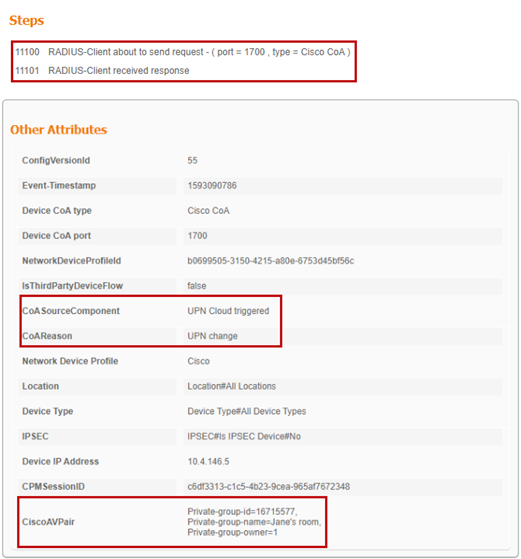
3. Upon successful authentication, sends a RADIUS response to the wireless controller containing three UDN-specific vendor specific attributes (VSA) used for UDN segmentation at the wireless controller and access point.
● cisco-av-pair = UDN:Private-group-id – UDN ID used to separate multicast/broadcast domains
● cisco-av-pair = UDN:Private-group-name – The UDN “name” of the room created by a user
● cisco-av-pair = UDN:Private-group-owner – Identifies if the device is the owner of the UDN
There is no manual, UDN specific configuration required at ISE. All configuration is performed via the on-premise Cisco DNA Center and the Cisco UDN Cloud service. Upon provisioning by the on-premise Cisco DNA Center, a new UDN pxGrid service is added which allows both the on-premise Cisco DNA Center and the cloud service to communicate with ISE via REST APIs. ISE makes use of a new pxGrid “status” topic whenever UDN assignments are created, updated, or deleted.
Upon Cisco DNA Center provisioning of ISE two new database tables are created. The first is for Device-UDN assignment records based on MAC addresses, this is used for device authentication. The second is for UDN properties as to whether UDN is enabled and if so the wireless controller and SSIDs it is enabled on; this is used to check whether the authentication request received has originated from a UDN enabled WLC or SSID requiring the extra UDN device lookup. Both database tables are replicated across a distributed ISE deployment.
A new logging option, the UDN logging component, has also been established. In a distributed deployment, the Policy Administration Node (PAN) records all activity originating from both the on-premise and cloud instantiations of Cisco DNA Center as well as change of authorization (CoA) activity between ISE and the WLC including CoA responses. The Policy Service Node (PSN) shows run-time activity during device onboarding including UDN lookup results for device MAC address as well as any changes to the local Device-UDN cache when information is replicated from the PAN.
During Cisco DNA Center provisioning of ISE, a new Authorization (AuthZ) Profile is also created and will be automatically applied to all existing Authorization Policies as a condition in addition to any that may exist. This AuthZ profile makes use of RADIUS attributes from the wireless controller as a network access device to determine that both the originating wireless controller and the SSID that the onboarding device is joining are UDN enabled before performing an actual UDN lookup. This minimizes the number of lookups required at ISE as devices authenticate throughout your network.
| Tech tip |
| The Cisco UDN solution requires an ISE Plus license for every user device. Note that if randomized MAC addresses are enabled on a device, each MAC address will consume one license. |
Catalyst 9800 wireless controller
The Cisco UDN solution only supports the IOS based Catalyst 9800 series physical and virtual wireless controllers; AireOS-based controllers and Catalyst 9800 embedded (switch or AP) controllers are not supported. With the introduction of UDN, SSIDs can be defined and dedicated to UDN in addition to those SSIDs dedicated to normal enterprise and guest wireless access. The UDN SSIDs can be configured for either 802.1x, MAC Auth Bypass (MAB), or pre-shared key (PSK). There are no restrictions associated with a mobile device that has been registered with a UDN via the Cisco UDN Mobile App, from accessing any other Enterprise SSID other than they will not have the same segmentation as when attached to the UDN. In the current implementation of UDN, only a single Catalyst 9800 controller or HA pair is supported. As a result, all devices and their UDNs are local to the WLC and the specific SSIDs associated with the UDN and roaming between controllers is not supported.
Prior to discovery and subsequent provisioning of the Catalyst 9800 WLC, it will be necessary to first define those SSIDs that will be used for UDN at the on-premise Cisco DNA Center. With the release of IOS-XE 17.3.1 for the WLC, additional UDN parameters have been added to the WLAN configuration, however, nothing needs to be defined at the WLC prior to execution of the Cisco DNA Center UDN Workflow at the on-premise Cisco DNA Center.
Once the configuration of the SSIDs has been completed at the on-premise Cisco DNA Center, a device discovery is launched to include the Catalyst 9800 in its inventory. After successful discovery of the wireless controller, provisioning of the controller is then launched from Cisco DNA Center. This will provision the WLC for communications with Cisco DNA Center. Once completed, it is at this point that the Cisco UDN Workflow, discussed previously, is launched at Cisco DNA Center for UDN specific configuration at the WLC and ISE. At this point, the UDN is fully functional.
The mDNS Gateway functionality of the Catalyst 9800 WLC is completely interoperable with the UDN functionality. The gateway functionality must be configured separately however, as automated provisioning of this functionality is not yet supported with the current release (2.1.1.3) of Cisco DNA Center. The mDNS Gateway functionality will be required for advertisement of Bonjour services across L3 networks. If your UDN deployment is deployed across multiple VLANs, mDNS Gateway will be required if devices in a UDN will need to discover devices in another VLAN.
| Tech tip |
| For more information regarding mDNS, please refer to the mDNS Deployment Guide for Cisco Catalyst 9800 WLC and the Cisco DNA Service for Bonjour Deployment Guide. |
If a user’s mobile device has been pre-registered off-site the device is all set to access the UDN SSID. If, however, due to MAC randomization they were unable to pre-register their device, they would join any SSID providing Internet access and register their device once attached to the wireless network. The SSID joined for registration while onsite, could be the UDN SSID or any other as long as the user has the credentials necessary to access the wireless network based on the security implemented.
Having registered to a UDN via the Cisco UDN Mobile App, as devices join the wireless UDN SSID, the wireless controller sends a RADIUS authentication request to ISE. In addition to the authentication method (802.1X, MAB, or PSK) based on wireless security configured for the UDN SSID, ISE performs a lookup for that device’s MAC address and returns the authentication results as well as RADIUS UDN ID to the wireless controller, if the MAC address is found in the ISE database. The MAC Addresses are populated in the ISE identity database by the Cisco UDN Cloud service at the time of device registration using the Cisco UDN Mobile App. In the event there is no UDN information associated with a device from the cloud service, ISE will not relay any specific UDN info back to the WLC and the device will be granted access if the authentication was successful.
When joining the UDN SSID, if authentication is successful but the device is not registered to a UDN, the device will still gain access to the network and will be assigned a UDN-ID of zero. With UDN-ID of zero, that device will be able to communicate in North/South fashion to the Internet and wired enterprise resources. It will not be able to communicate with any other wireless devices within that UDN SSID.
When endpoints associated with a specific UDN attach to the defined UDN SSID, the WLC will segment the various discovery protocol traffic such as mDNS, to only that UDN. This will work across all Wave 2 APs and Catalyst 9100 APs. As a result, only those devices within a specific UDN will see the services broadcasted by any device within that UDN. Segmentation of multicast and broadcast advertisements is performed directly on the Cisco access points. Unicast controls are implemented at the WLC.
| Tech tip |
| When deploying Cisco UDN, discovery and streaming is limited to registered devices within the UDN for wireless devices such as MacBooks, iPhones, and iPads. For the Apple TV, if the AirPlay settings are left in their default state, devices with Bluetooth enabled and within roughly 30 feet of the Apple TV, the signal distance for Bluetooth Low Energy (BLE), will still be able to discover and stream to an Apple TV registered within a UDN. Please refer to Appendix C for the procedure to disable AirPlay over Bluetooth if you would like to change this behavior. |
By default, unicast traffic is permitted between UDNs while multicast traffic such as mDNS is always contained within the UDN. The default behavior of allowing unicast communications between UDNs can be changed however, while running the UDN Workflow at Cisco DNA Center or in the wireless security policy associated with the UDN WLAN. With unicast blocking enabled, mobile devices can only communicate with other devices in that UDN or anything northbound, external to the wireless network.
| Today the concept of a UDN shared device or services, such as a printer for example, accessible from all UDNs, is not supported. In the future there are plans to support this functionality. |
Device registration and onboarding
The following diagram provides an overview of the communications during device registration and subsequently attaching to the wireless network.
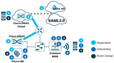
Device registration flow
1. Using the Cisco UDN mobile app, the device registers with Cisco UDN Cloud.
2. The user is prompted for authentication credentials. Cisco UDN Cloud authenticates the user either against Azure AD or an Identity Provider (IDP) via SAML 2.0.
3. The UDN is created, and MAC address information for the devices that will be members of that UDN collected. This can be performed offsite, before the device attaches to the UDN if MAC randomization is disabled on the device, or onsite where MAC randomization can be enabled.
4. Upon device registration, Cisco DNAC Cloud communicates with the on-premise Cisco DNA Center which in turn relays registration information for the device including the UDN ID, UDN name and MAC Addresses entered.
5. Registration information is then passed to Cisco ISE and stored in a database for later use when devices join the SSID and gain access to the wireless network.
Device network access
1. When the device is brought onsite, the UDN SSID will be selected at the device. The SSID can be configured with either a pre-shared key (PSK), 802.1X, or MAB flow to authenticate the device.
2. A RADIUS authentication request is sent to ISE from the wireless controller.
3. ISE checks its database to perform a lookup of the MAC address in it UDN database.
4. Upon a successful lookup, ISE passes the RADIUS response back to the WLC along with vendor specific attributes identifying the
● private-group-id – Used by the WLC to identify the UDN and isolating multicast and broadcast traffic between UDNs
● private-group-name – Name of the room/UDN which the user defined
● private-group-owner – If the UDN is owned by that device
5. The wireless controller programs the access point with the appropriate UDN information to block multicast and broadcast traffic between UDN. Optionally, if selected to do so during wireless controller provisioning from the Cisco DNA Center UD Workflow, unicast blocking between UDNs is enabled at the wireless controller.
Room change
1. The device either removes itself or is removed by the owner of the UDN
2. The ISE database is updated with device removal and the MAC address-UDN mapping is removed from the database.
3. ISE send a CoA to the wireless controller for device to re-authenticate.
Product Requirements
The following table provides the software version validated within this deployment guide.
| Device |
Version |
| Cisco DNA Center |
2.1.2.3 or later |
| ISE |
2.7 Patch 2 or later with Plus or Apex licenses |
| Catalyst 9800 Wireless Lan Controller |
IOS-XE 17.3.1with DNA Advantage licenses for APs |
| Cisco Wireless AP |
IOS-XE 17.3.1 or later |
| Cisco UDN Mobile App |
1.2 |
| Cisco UDN Cloud |
Not Applicable |
Scale
The Following table provides scale numbers for the solution.
| Device |
Scale |
| Cisco Catalyst 9800-80 |
Up to 64,000 unique User Defined Networks per controller |
| Cisco Catalyst 9800-40 |
Up to 32,000 unique User Defined Networks per controller |
| Cisco Catalyst 9800-L |
Up to 5,000 unique User Defined Networks per controller |
| Cisco Catalyst 9800-CL |
10,000, 32,000 or 64,000 unique User Defined Networks per controller |
| Cisco ISE |
Up to 2 Million Endpoints |
| Cisco UDN Cloud |
30 Registration/Invite/De-Register events per second per Tenant (organization) |
This process will take you through the steps necessary to set up your devices to be UDN ready. These include Integrating ISE and Cisco DNA Center, discovery of the Catalyst 9800 Wireless Lan Controller, and creating Network Settings and a Site Hierarchy in Cisco DNA Center.
If you have already done these steps, you can skip ahead to Process: Configuring Wireless settings for WLAN Deployment.
Procedure 1. ISE and Cisco DNA Center Integration
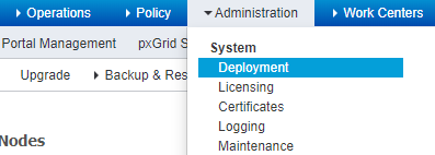
Step 1. Login to the Cisco ISE Primary Admin Node (PAN) and Navigate to Administration>Deployment
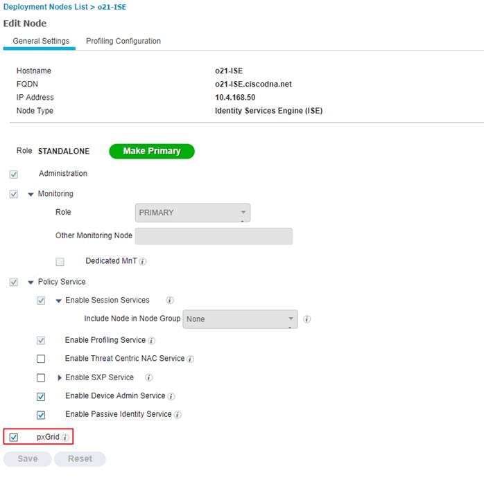
Step 2. Select the hostname of the ISE node.

Step 3. Under General Setting, make sure the PxGrid checkbox is selected and hit Save.
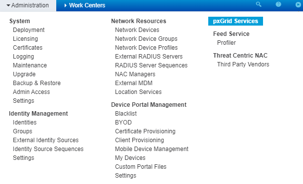
Step 4. Navigate to Administration>PxGrid Services>Settings.
Step 5. Check Automatically approve new certificate-based accounts and click Save.
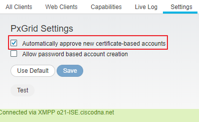
Step 6. Navigate to Administration>System>Setting>ERS Settings.
Step 7. Select Enable ERS for Read/Write and click Save.
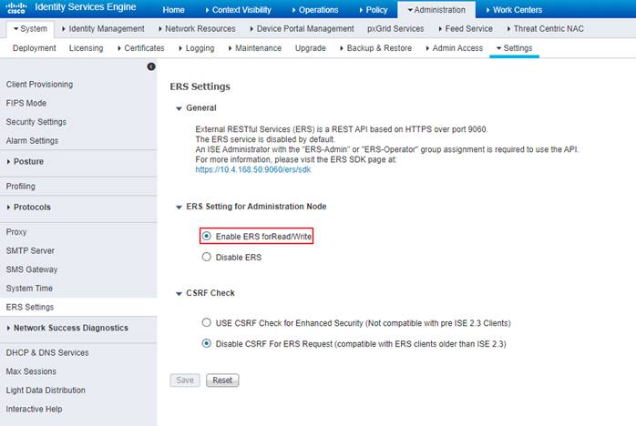
| Tech tip |
| Ensure that CSRF Check is disabled otherwise you will not be able to establish a pxGrid connection between Cisco DNA Center and ISE. |
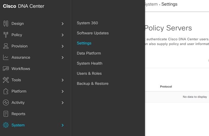
Step 8. In Cisco DNA Center navigate to System>Settings.
Step 9. Scroll down on the left and select Authentication and Policy Servers.
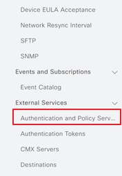
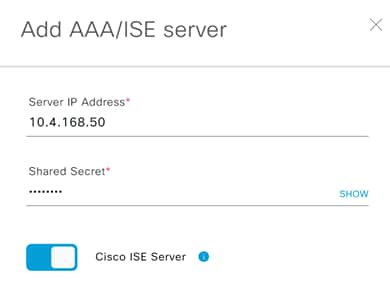
Step 10. Enter the ISE PAN management IP address and enter a Shared Secret. The shared secret is just an arbitrary secret you define to be used for pxGrid communication between ISE and Cisco DNA Center.
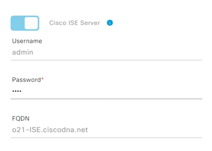
Step 11. Click on the slider next to Cisco ISE Server.
Step 12. Enter the ISE admin credentials.
Step 13. Enter the FQDN for the Cisco ISE server.
| Tech tip |
| The FQDN must be reachable through DNS. |
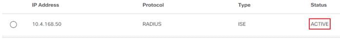
Step 14. Click Save and wait for the Status to go from In Progress to Active.
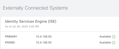
Step 15. Also ensure that ISE is listed as Available in Cisco DNA Center System 360 by navigating from the Cisco DNAC menu to System > System 360 and scroll down to Externally Connected Systems.
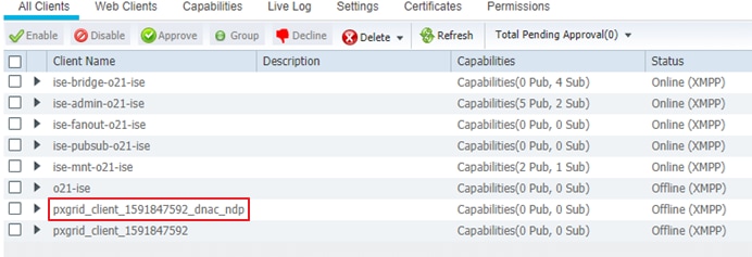
Step 16. In ISE navigate to Administration>pxGrid Services and under All Clients, see that your Cisco DNA Center subscriber name shows up.
Procedure 2. Catalyst 9800 Wireless Lan Controller Discovery
In this procedure we will go through the steps necessary to bring the Catalyst 9800 WLC into Cisco DNA Center’s inventory.
| Tech tip |
| The Catalyst 9800 must only have the initial, Day 0 configuration for IP reachability, SNMP, and SSH/Telnet. Any brownfield wireless configuration including SSID, network, or VLAN configuration will cause issues with Cisco DNA Center provisioning. |
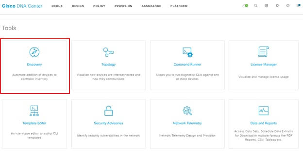
Step 1. Login to Cisco DNA Center and select Discovery in the Tools section at the bottom of the homepage.
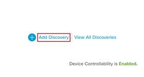
Step 2. Click Add Discovery.
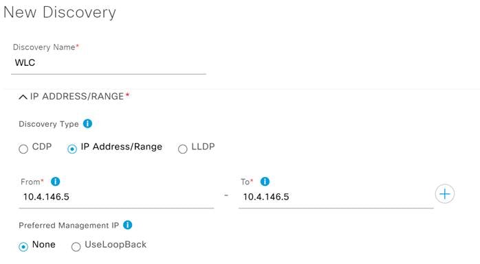
Step 3. Add a name for this discovery under Discovery Name.
Step 4. Under Discovery Type select IP Address/Range and in the From – To section enter the Management IP for the Catalyst 9800 WLC.
| Tech tip |
| Cisco Wireless Lan Controllers must be discovered using the Management IP. If not Wireless Controller 360 and AP 360 pages will not display data. |
Step 5. Under Preferred Management, select one of the following options.
● None: Allows the device to use any of its IP addresses.
● Use Loopback: Specify the device’s loopback interface as the management IP.
Step 6. Expand the Credentials section and click Add Credentials.
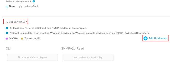
Step 7. Under the CLI section enter the credentials needed to access the CLI of the device and click Save.
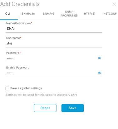
| Tech tip |
| Do not use "admin" as the username for your device CLI credentials. If you do, this can result in you not being able to login to your devices. |
Step 8. Next add the SNMP credentials that will be used to connect to the WLC.
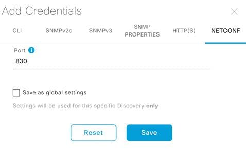
Step 9. Click NETCONF, leave the default port of 830 and click Save.
Step 10. Exit out of the Add Credentials menu by clicking the X at the top right corner.
Step 11. Check to make sure all your credentials are set by checking the blue slider indicators and click Discover.
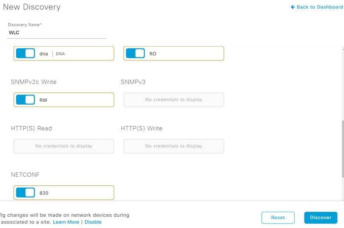
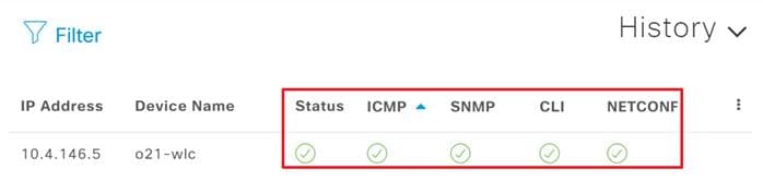
Step 12. After a few moments you should see your device discovered, check the status indicators to make sure everything was discovered correctly.
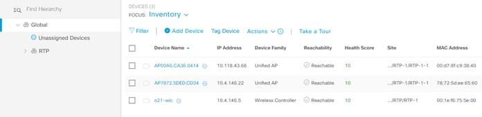
Step 13. Navigate to Provision>Inventory and you should now see your WLC as well as any APs connected to the controller in your inventory.
Procedure 3. Creating a Site Hierarchy
Cisco DNA Center uses a Network Hierarchy of areas that contain sub-areas of buildings and floors. Devices are assigned to these buildings or floors and will then be provisioned depending on the Network Settings configured for that level.
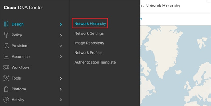
Step 1. In Cisco DNA Center, navigate to Designs >Network Hierarchy.
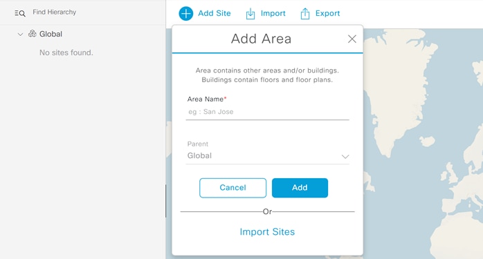
Step 2. Click the cog wheel next to Global and select Add Area.
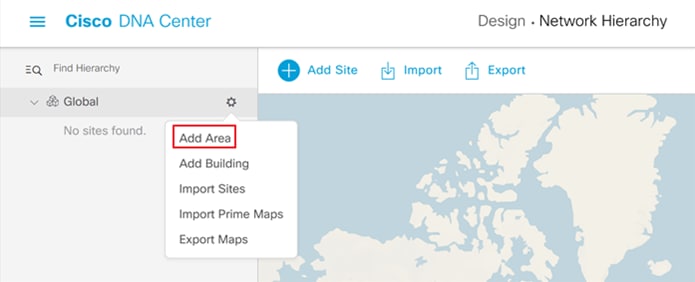
Step 3. In the resulting pop-up enter your Area Name and click Add.
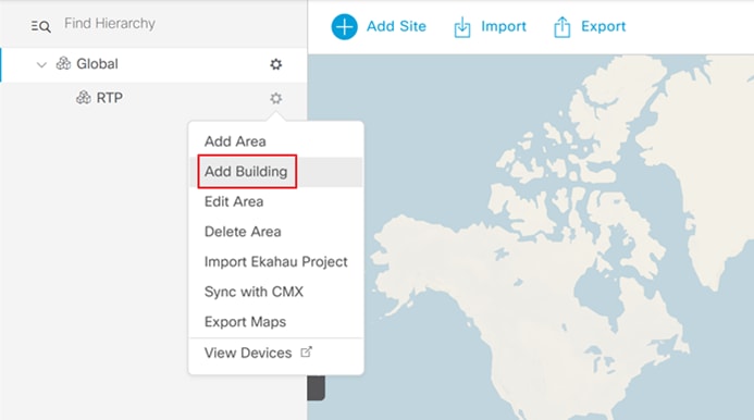
Step 4. Next to the newly created Area, click the cog wheel and select Add Building.
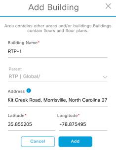
Step 5. In the resulting pop-up enter the building name and address of your building, this will fill in the Latitude and Longitude automatically.
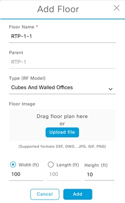
Step 6. Next to the newly added building, click the cog wheel and select Add Floor.
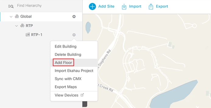
Step 7. Enter a Floor Name and click Add. Optionally, upload a floor plan.
Step 8. Repeat these steps for any additional Sites, Buildings, or Floors in your environment.
Procedure 4. Creating Network Settings
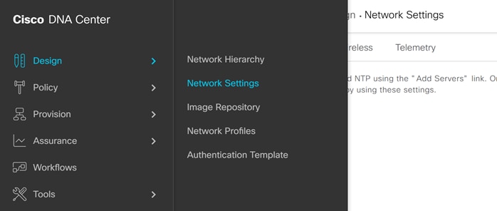
Step 1. In Cisco DNA Center navigate to Design>Network Settings>Network.
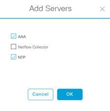
Step 2. Click Add Servers and Select AAA and NTP and click OK.
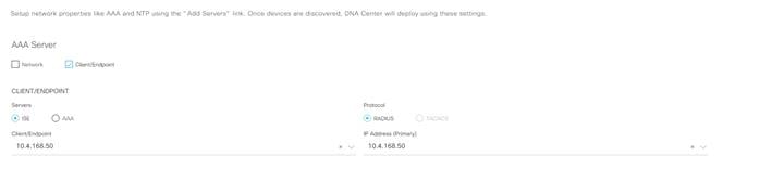
Step 3. Under AAA server select the Client/Endpoint check box and in the drop down select the IP address for your ISE server.
Step 4. Scroll down and enter the information for DNS and DHCP servers.
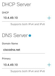
Step 5. Enter the information for the network NTP server and click Save.
Process: Configuring Wireless settings for WLAN Deployment.
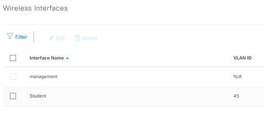
Procedure 1. Configure Wireless Interfaces
Before we configure the SSID, we must first configure the interface the WLAN traffic will be dumped off from the Catalyst 9800 WLC.
Step 1. In Cisco DNA Center, Navigate to Design>Network Settings>Wireless.
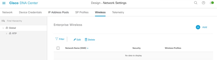
Step 2. At the Global level, click Add next to Wireless Interfaces.
Step 3. In the Create a Wireless Interface side panel enter the Interface Name and the VLAN ID for the corresponding VLAN on the network and click Save.
| Tech tip |
| This will be the VLAN the wireless traffic is dumped off from the Catalyst 9800 WLC. |
Step 4. You should now see your newly created interface below the Wireless Interfaces section.
Procedure 2. Configuring the Wireless Networks
In this section we will be creating the Wireless SSID to be used for UDN. The WLAN in this example makes use of a PSK.
| Tech tip |
| Cisco DNA Center must be used to create the wireless SSIDs on the Catalyst 9800 wireless controller. Issues with both UDN creation and telemetry will ensue if the SSID is created through the WLC user interface and not at Cisco DNA Center. Editing the WLC SSID from the WLC UI is fine after initial creation. |
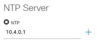
Step 1. In Cisco DNA Center, navigate to Design>Network Settings>Wireless and click Add next to Enterprise Wireless.
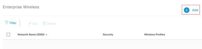
Step 2. This will bring up the Create an Enterprise Wireless Network workflow.
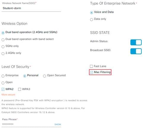
Step 3. Name your Wireless Network and select your level of security. For this guide we will be using WPA2 Personal.
Step 4. Check the box next to Mac Filtering. When configuring WPA2 Enterprise with 802.1X MAC filtering should not be enabled.
| Tech tip |
| Enabling MAC Filtering will not be needed for UDN in Cisco DNA Center 2.1.1.3 as it will automatically be configured during the UDN Workflow. |
Step 5. When finished click Next, this will bring up the Wireless Profile page.
Step 6. Name the wireless profile and under Fabric select No.
Step 7. Under Select Interface, choose the interface created in the previous steps.

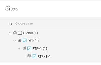
Step 8. Click Sites and in the resulting pop-up select the sites at which you want to deploy this SSID.
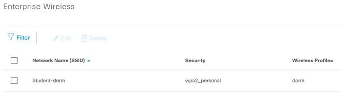
Step 9. When done click Finish. You should now see your new wireless network under Enterprise Wireless.
Procedure 3. Provision the WLC
In this section, we will now push the configuration down to the Catalyst 9800 WLC.
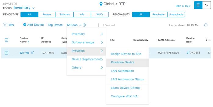
Step 1. In Cisco DNA Center navigate to Provision>Inventory.
Step 2. Click the check box next to your WLC and under Actions select Provision>Provision Device.
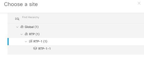
Step 3. In the resulting pop-up click Choose a Site, then select where you would like to assign the WLC and click Save and Next.
Step 4. In the Configuration screen double check to make sure everything looks correct and click Next.
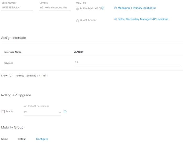
Step 5. Hit Next on both the Model Configuration and Advanced Configuration pages.
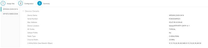
Step 6. On the summary page double check your configuration, when finished click Deploy.
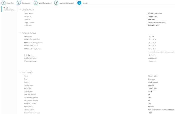
Procedure 4. Provisioning of the APs
Step 1. Navigate to Provision>Inventory in Cisco DNA Center.
Step 2. Any APs connected to the WLC will show up in inventory.
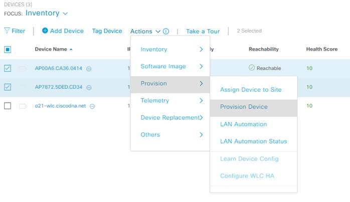
Step 3. Select the APs you would like to provision then under Actions select Provision>Provision Device.
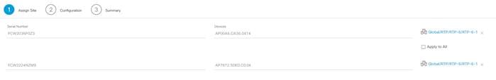
Step 4. Select the floor you would like to deploy for each AP and click Next.
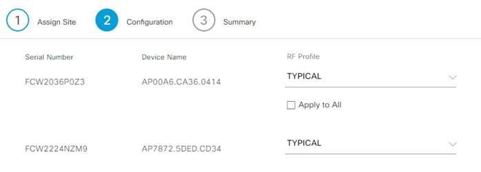
Step 5. Select the RF profile to be used by each AP and click Next.
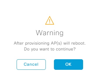
Step 6. On the summary page, doublecheck the configuration and click Deploy.
Step 7. Click OK on the warning saying the APs will reboot.
Process: Cisco UDN Cloud Authentication/SSO
Authentication for the Cisco Mobile App is performed via Single Sign On (SSO) using an external Identity Provider. The IdP can either be Azure AD or a SAML 2.0 enabled service. At the present time only Shibboleth, Microsoft Azure AD, or Microsoft ADFS have been validated using SAML 2.0. The following processes will be provided showing you the use of Azure AD or the use of SAML 2.0 in conjunction with Microsoft ADFS; one of these two authentication methods can be selected:
● Process 1 Microsoft Azure AD/OpenID protocol
● Process 2 Microsoft ADFS/SAML 2.0 protocol
Shibboleth and Azure AD are two other options when using SAML, but they will not be covered here. Even though not covered the Cisco UDN Cloud configuration will be the same with the exception that the Domain and Metadata URL will obviously be unique.
Process 1: Azure AD and UDN Cloud
This process will take you through the steps for creating a tenant in the UDN cloud as well as the corresponding Microsoft Azure AD configuration for use with the OpenID protocol. UDN users must be defined in both Azure AD as well as in Cisco UDN Cloud. Within this process, we will show two procedures. The first procedure will make use of Azure AD group attributes such that manual user creation is not required at Cisco UDN Cloud. As a member of a specific group in Azure AD, the user will be authenticated, and by virtue of that group attribute being matched, the user identity will be created in DNA Center Cloud automatically. The second is the manual creation of users in both Azure AD as well as the required, duplicate user information being added to Cisco UDN Cloud.
Procedure 1. Azure AD Configuration
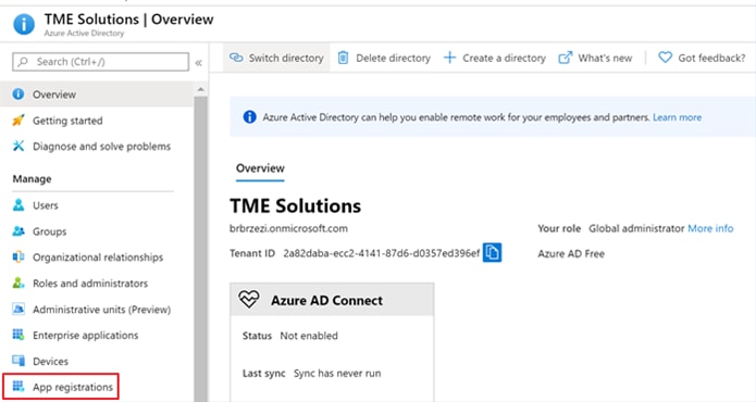
Step 1. Navigate to Azure AD and under Manage select App Registrations.
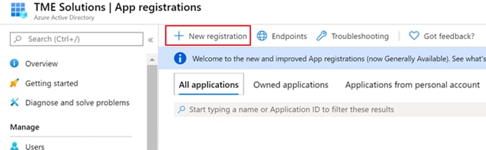
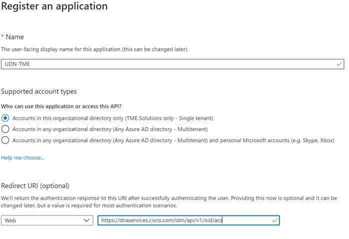
Step 2. Select + New registration.
Step 3. In the Register an application screen, enter a name.
Step 4. Under Redirect URI, select Web and enter the following: https://dnaservices.cisco.com/idm/api/v1/oid/acs
Step 5. When finished click Register.
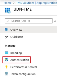
Step 6. Once created click Authentication.
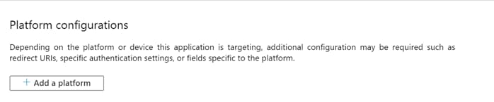
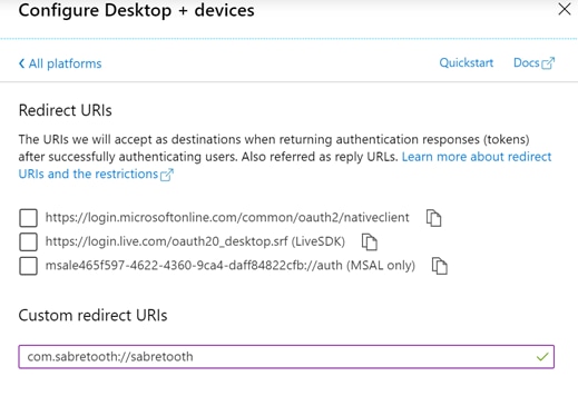
Step 7. Select + Add a platform.
Step 8. Select Mobile and desktop applications.
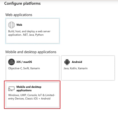
Step 9. Under Custom redirect URIs enter the following: com.sabretooth://sabretooth
Step 10. Click Configure when finished.
In the next steps we will be collecting information to configure AAD as an SSO source for UDN cloud. Please capture this information in a separate document or notepad.
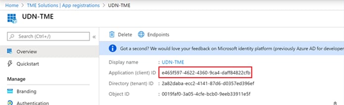
Step 11. Click Overview and capture the Application (client) ID.
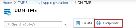
Step 12. Click Endpoints.
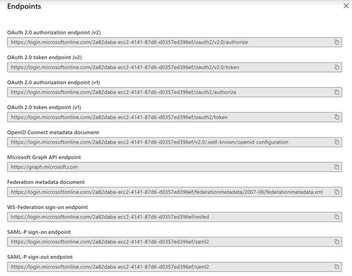
Step 13. Collect the information for the following:
· OAuth 2.0 token endpoint (v1)
· OAuth 2.0 authorization endpoint (v1)
· OpenID Connect metadata document
| Tech tip |
| In the OpenID Connect metadata document you must remove the /v2.0 from the URL. |
Step 14. Navigate to Certificates & secrets and select +New client secret.
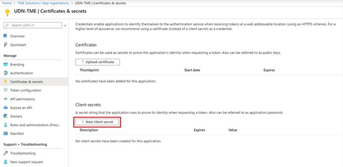
Step 15. Provide a description and select an expiration for the client secret.
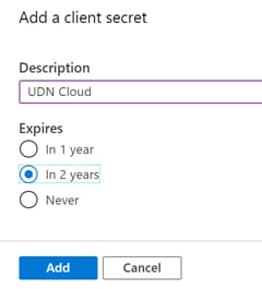
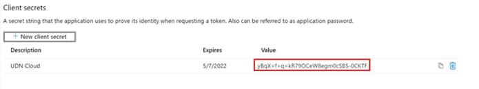
Step 16. Click Add, then collect the value for your newly created client secret.
Step 17. Navigate back to your AAD overview and capture the domain.
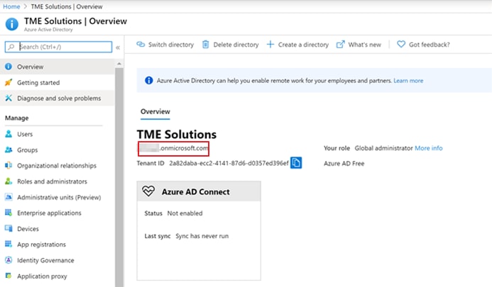
Make sure to save all captured information for the steps in Procedure 2.
Once the previous steps are completed, we will now optionally create and collect the Azure AD Group information necessary for the Cisco UDN Mobile App SSO at DNA Center Cloud. Remember that the benefit of using group attributes is that there will be no need to duplicate user creation in Cisco UDN Cloud; they only need to be present in Azure AD and assigned to the appropriate group.
Step 18. Navigate to Groups to create a new group and click +Add Group.
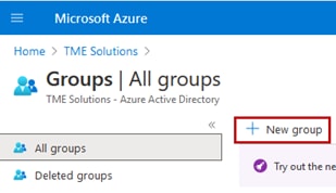
Step 19. After creation of the group, make note of it’s Object ID as it will be required when configuring Cisco UDN Cloud. Navigate to Groups select the desired group and click Members then Add Members to the appropriate group.
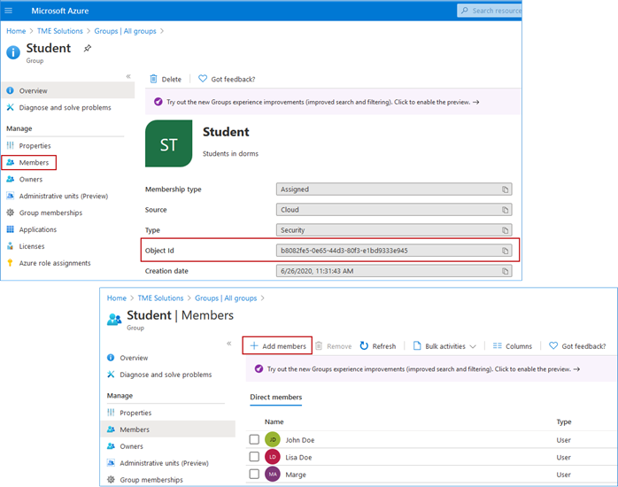
Step 20. Navigate back to the Azure AD Tenant Overview page and select App registrations then select the App previously configured.
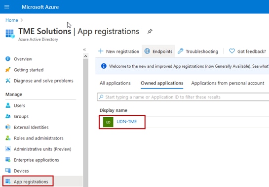
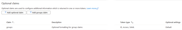
Step 21. Select Token Configuration and click +Add groups claim.
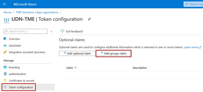
Step 22. The Edit groups claim window opens. Select Security groups and then click the radio buttons for ID-Group ID, Access-Group ID, and optionally SAML-Group ID.
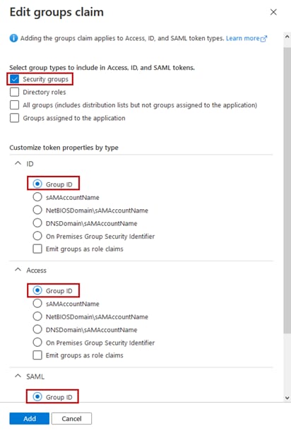
Step 23. Click Add and the Optional claims for groups are created. The remaing configuration steps to use group attributes will be completed in the next procedure to be completed at Cisco UDN Cloud.
Procedure 2. Cloud Tenant Creation and setup.
Step 1. Log in to https://UDN.cisco.com Using your CCO ID.
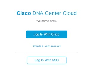
Step 2. A pop up will appear confirming that this is the profile you would like to register with, click to agree to the terms and select Create Account.
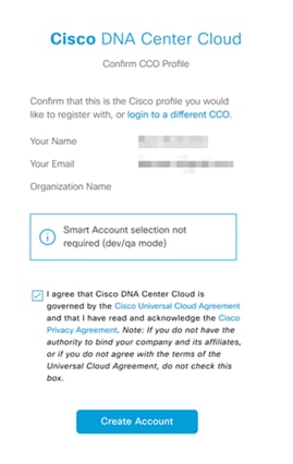
Step 3. A tenant will then be created in the UDN cloud with the CCO used with administrator privileges.
Procedure 3. Configuring Single Sign-on with individual user information
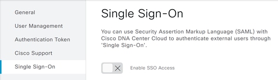
Step 1. Once logged into the UDN cloud, Click the menu button at the top left of the screen and select System.

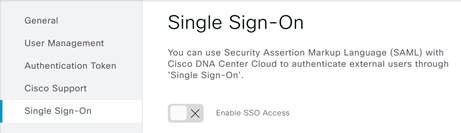
Step 2. Select Single-Sign-On. Then click the slider next to Enable SSO Access.
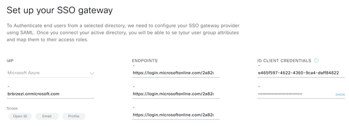
Step 3. Enter the information taken in the previous steps to the corresponding attribute. When finished click Next and Enable SSO.
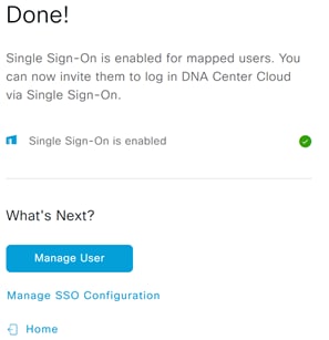
Step 4. You should now see the single sign-on confirmation screen.
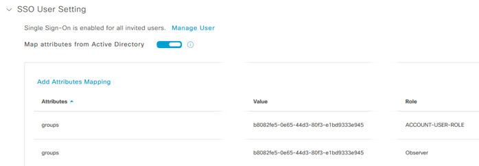
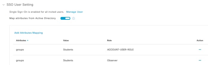
Step 5. To optionally continue to configure group attributes, select Manage SSO Configuration as seen in the screenshot above and scrolling down on the page click on SSO User Setting then click on the slider.
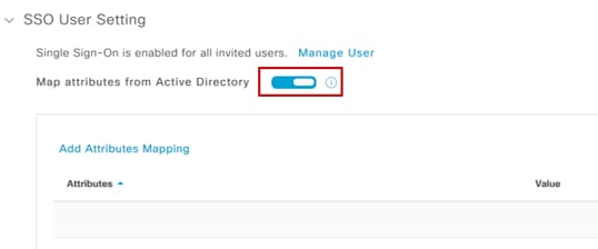
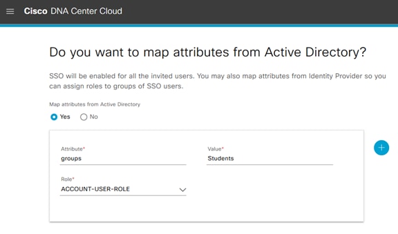
Step 6. Click Add Attributes Mapping and the configuration window opens. For Attribute enter “groups”; note that this is case sensitive. For Value use the Group Object ID collected during group creation and select the appropriate role. For normal users this will be the ACCOUNT-USER-ROLE. Click Add.
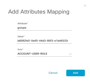
You will notice that two “groups” attributes are added, one for ACCOUNT-USER-ROLE and the other for Observer role. This is normal.
Procedure 4. Enroll Admin and Student Users
The following steps are only required if Azure AD group attributes aren’t being used. In the following we are only showing the addition of users within Cisco UDN Cloud. It is assumed that a corresponding user exists in Azure AD.
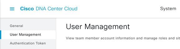
Step 1. In the UDN cloud, Click the menu button at the top left of the screen and select System.
Step 2. Select User Management.
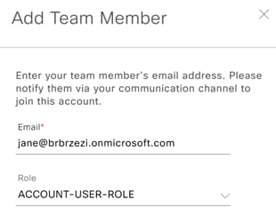
Step 3. Click Add at the top right corner.
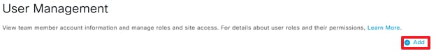
Step 4. Enter the email and role of the new user with the role of ACCOUNT-USER-ROLE for students and ADMIN for additional admin users.
Step 5. Repeat these steps for all wanted users.
Process 2: Cloud Authentication with SAML and Microsoft ADFS
In addition to support for OpenID and Microsoft Azure AD, Cisco UDN Cloud authentication using SAML 2.0 is also supported. In this process, we will detail the steps required to configure Microsoft ADFS using SAML to provide the cloud authentication for the Cisco UDN Mobile App.
| Tech tip |
| This process assumes that you have Microsoft ADFS installed in your environment. It is beyond the scope of this document to discuss design and deployment of ADFS in your environment. Also be aware that these steps were documented using Microsoft Windows Server 2016 in conjunction with ADFS v4.0 (2016). |
Procedure 1. Configure Microsoft ADFS
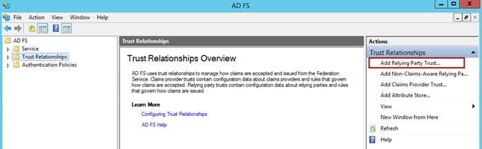
Step 1. Open the Microsoft ADFS Management Console.
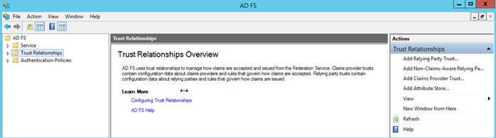
Step 2. Navigate to Trust Relationships > Relying Party Trusts > Add Relying Party Trust…
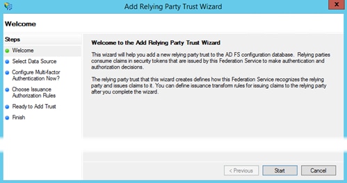
Step 3. The Add Relying Party Trust Wizard opens. Click Start.
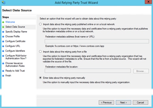
Step 4. In the Select Data Source window choose the third option, Enter data about the relying party manually.
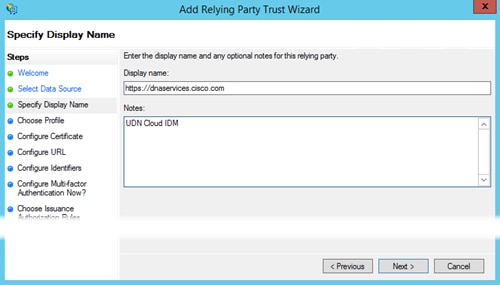
Step 5. For the Display Name add a name to identify the relying party. This can be any meaningful name you want to use and then click Next.
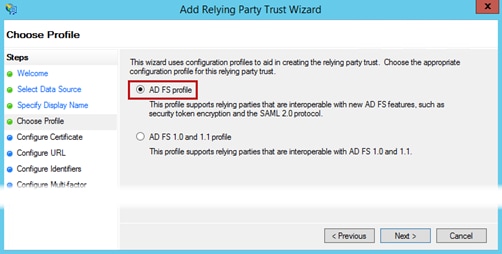
Step 6. Select the first option, Add FS profile.
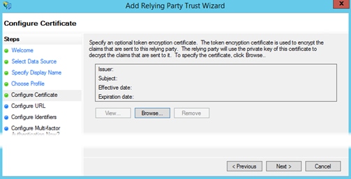
Step 7. Optionally, choose a certificate to be used for token encryption of claims sent to this relying party then click Next. Otherwise, just click Next.
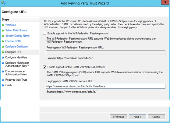
Step 8. In the Configure URL window, check the Enable support for SAML 2.0 WebSSO protocol box and then enter in the following URL https://dnaservices.cisco.com/idm/api/v1/saml/acs and click Next.
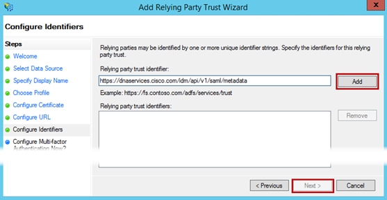
Step 9. In the Configure identifiers window, enter https://dnaservices.cisco.com.com/idm/api/v1/saml/metadata click Add and the Next.
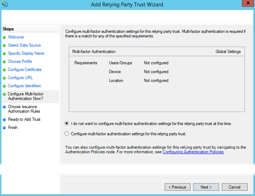
Step 10. Select I do not want to configure multi-factor authentication… if you do not want to make use of the optional multi-factor authentication settings then click Next.
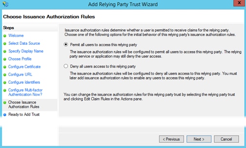
Step 11. Select Permit all users… such that authentication requests from the relying party trust for every user, will be permitted. Our example depicts the default scenario. Click Next.
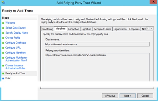
Step 12. Verify that the setting in the various tabs are correct and click Next.
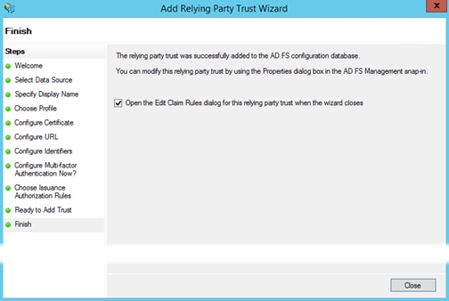
Step 13. Addition of the relying party trust is now completed. Check the box next to Open the edit… and click Close.
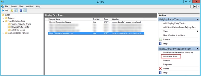
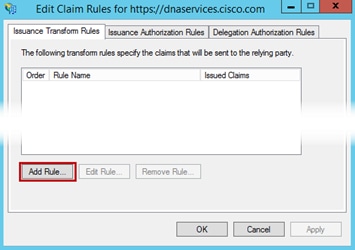
Step 14. Once completed, from the ADFS Management Console, select the relying party trust you just created and select Edit Claims Rules…
Step 15. Next select Add Rule.
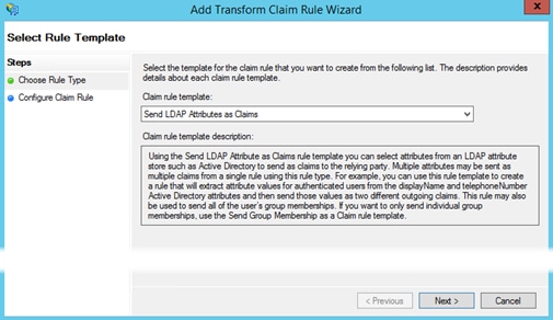
Step 16. In the drop-down select Send LDAP Attributes as Claims then click Next.
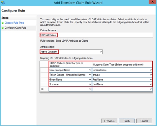
Step 18. Next click Apply and then OK.
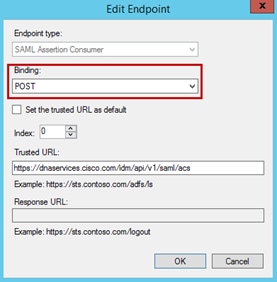
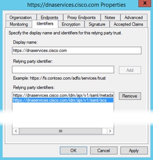
Step 19. At the ADFS Management Console, right click on the relying party trust you created and in the drop-down menu select Properties. Go to the Endpoints tab and select the URL then click Edit.
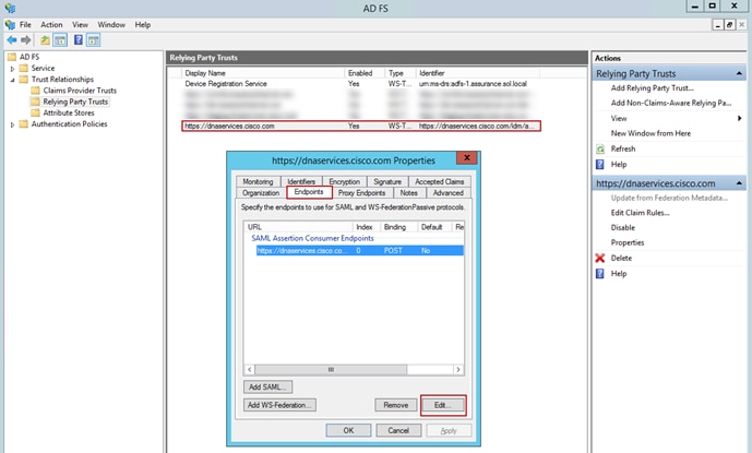
Step 20. Verify that the Binding is set to Post and that the Trusted URL is set to https://dnaservices.cisco.com/idm/api/v1/saml/acs. Click OK.
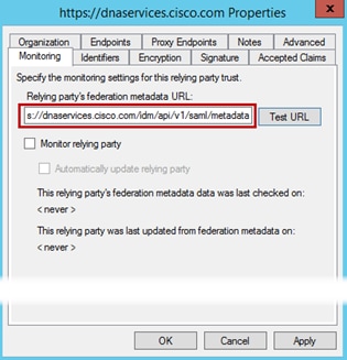
Step 21. Go to the Monitoring tab. Add https://dnaservices.cisco.com/idm/api/v1/saml/metadata then click Apply and OK.
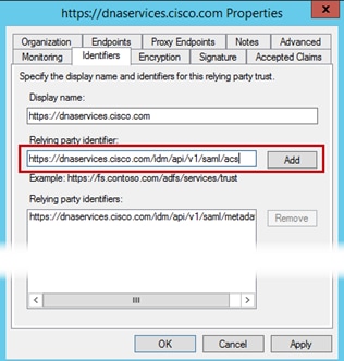
Step 22. Go to the Identifiers tab and enter https://dnaservices.cisco.com/idm/api/v1/saml/acs. Click Add, then Apply, and finally OK.
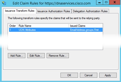
Step 23. You should now see the following. This completes the configuration required at Microsoft ADFS.
Procedure 2. Cloud Tenant Creation and setup.
Step 1. Log in to https://UDN.cisco.com Using your CCO ID.
Step 2. A pop up will appear confirming that this is the profile you would like to register with, click to agree to the terms and select Create Account.

Step 3. A tenant will then be created in the UDN cloud with the CCO used with administrator privileges.
Procedure 3. Configuring Single Sign-on with individual user information
Step 1. Once logged into the UDN cloud, Click the menu button at the top left of the screen and select System.
Step 2. Select Single-Sign-On. Then click the slider next to Enable SSO Access.
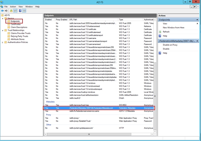
Step 3. Prior to proceeding with the SSO configuration, you will need to have the SAML metadata URL to complete the UDN Cloud configuration. At the Microsoft ADFS Management Console, navigate to Service > Endpoints and in the Metadata section you will find the metadata XML file. Make note of the path to the file which will be required in the next step.
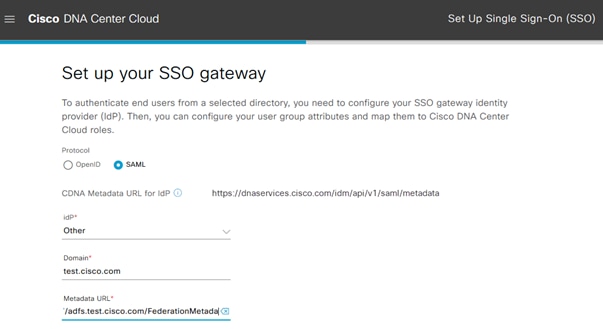
Step 4. Back at the Cisco UDN Cloud UI, once SSO is enabled the configuration window opens. Select SAML for the Protocol. For IdP, select Other from the drop-down. For Domain, enter your Active Directory domain name. Under Metadata URL enter https://<ADFS server FQDN>/FederationMetadata/2007-06/FederationMetadata.xml. Click Next.
You will now have a chance to map Active Directory Attributes used for SSO. The benefit of doing so is that when a user authenticates for the first time with the Cisco UDN Mobile App, the user will be automatically created in the UDN Cloud tenant, eliminating the requirement to create them manually. Should you choose not to do so, the manual user creation is documented in the preceding process (Azure AD).
Step 5. Select Yes to Map attributes. For Attribute we use the Token-Groups attribute from ADFS. This is taken from ADFS in Procedure1/Step16 earlier. Enter groups which is mapped to Token-Groups in ADFS and for Value enter the name of an existing AD group; note that these are all case sensitive and must match exactly. For Role, select ACCOUNT-USER-ROLE from the drop-down and click Next.
Step 6. In the summary screen that appears, select Enable SSO.
Step 7. You have nearly completed the SSO Configuration for the Cisco UDN Cloud. If you select Manage SSO Configuration from the completion window that appears, you will notice that a second attribute mapping is automatically created with a Role of Observer. This is completely normal and in fact required. Do not delete that mapping or SSO will break.
Process: Mobile App Customization
Procedure 1. Support Contacts
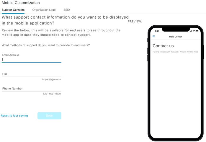
In this section, you can provide contact information for the helpdesk in case the student needs assistance with UDN. You can provide all contact methods or a subset. The preview screen will reflect what the student will see when they select Settings > Contact us within the UDN Mobile App
Step 1. Navigate to Manage>Mobile Customization>Support Contacts.
Step 2. Enter an Email, URL or Phone Number to be used for UDN support.
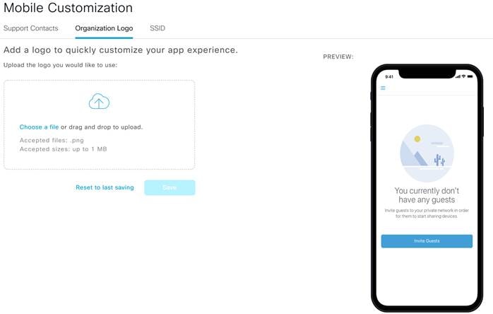
Procedure 2. Organization Logo
In this section a company or school logo can be uploaded which will be visible by users in the Cisco UDN Application. The logo must be in PNG format, less than 1 MB, and equal to or larger than 512 x 512 pixels.
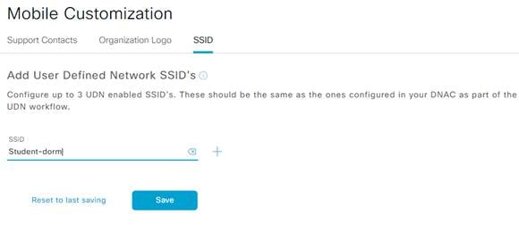
Procedure 3. Add SSID to UDN Cloud
In this section you can add up to three SSIDs used at the campus. This is needed for two reasons.
· Disable Mobile App Wi-Fi scanning – While this is a nice feature, you may not want the students to scan while on the campus network. Wi-Fi scanning will be disabled when connected to the SSID specified here.
· MAC Address Randomization – Certain wireless devices, for security, use a random MAC Address for each SSID it connects to. While not a bad practice, this can cause issues with device registration. Adding the SSID here makes it so users can only add random MAC addresses while connected to the SSID. More information about Randomized MAC Addresses can be found in Appendix B.
| Tech tip |
| At least one SSID is needed for the UDN Mobile App to work. |
Step 1. In the UDN Cloud navigate to Manage>Mobile Customization>SSID.
Step 2. Enter the SSID to be used for UDN and click Save.
Procedure 1. Cisco DNA Center UDN Workflow
This section will go through the UDN Workflow on Cisco DNA Center to integrate with the UDN cloud as well as enable UDN on the SSID.
| Tech tip |
| At the present time, DNAC clustering is not supported. Support for DNAC clustering will be available in a future release of the solution. |
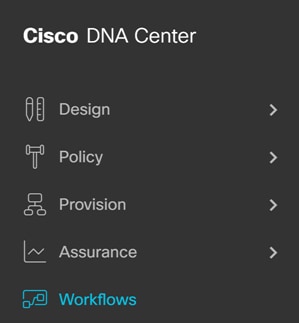
Step 1. In Cisco DNA Center Navigate to Workflows.
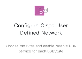
Step 2. Click Configure Cisco User Defined Network and then Let’s do it.
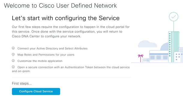
Step 3. On the welcome page click Configure Cloud Service.
Step 4. This will take you back to the UDN cloud, login if you are not already.
Step 5. Navigate to System>Authentication Token.
Step 6. Enter the FQDN for your Cisco DNA Center and then click Generate New Token.
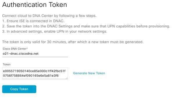
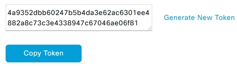
Step 7. Once generated, click Copy Token.
Step 8. Navigate back to Cisco DNA Center and click Next.
Step 9. Paste the Authentication Token copied from the previous step and click Connect.
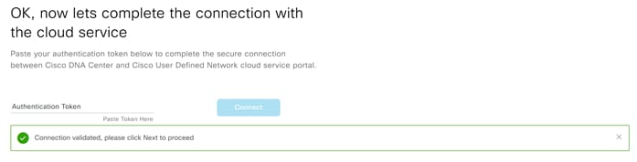
Step 10. You should now see the Connection validated message, click Next to continue.
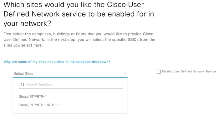
Step 11. In the next screen, select the site you would like to deploy UDN and hit Next.
| Tech tip |
| This must correspond with the Sites at which you deployed the SSID. |
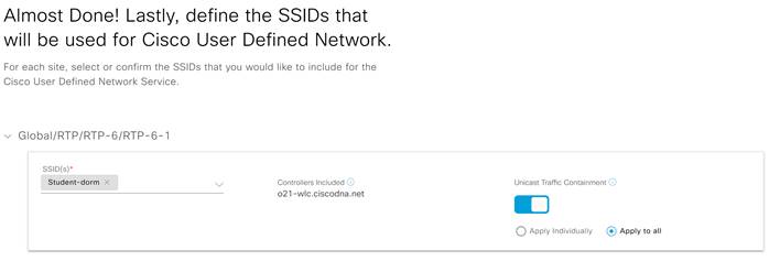
Step 12. In the next screen, select the SSID to be used for UDN and click Next.
Step 13. Optionally, click the slider next to Unicast Traffic Containment.
| Tech tip |
| Unicast Traffic Containment enables segmentation of all traffic between different UDNs. Without this option only link-local multicast traffic is filtered between UDNs. |
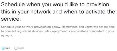
Step 14. Select when you would like to provision and click Next.
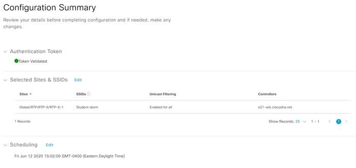
Step 15. Look over the summary and when ready click Configure.
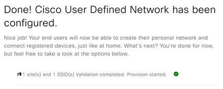
Step 16. Your SSID will now be configured for UDN.
| Tech tip |
| If the client VLAN spans multiple VLANs or the UDN SSIDs are on different VLANs mDNS gateway needs to be configured on the Catalyst 9800 WLC. These steps can be found in Appendix A: Configuring . |
Operate
Process: Adding devices and Guests to UDN.
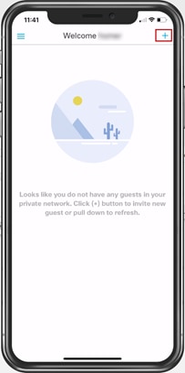
This section will go over the user experience in using the Cisco UDN application to add their devices as well as guest users.
Procedure 1. Adding devices to UDN.
Step 1. Open the Cisco UDN mobile app and login using your email and password.
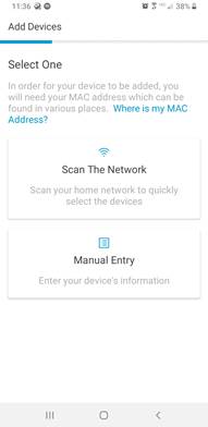
Step 2. Select Manual Entry.
| Tech tip |
| The Scan the Network feature is currently only available on Android at this time. This option will allow you to scan the network you are currently connected to for endpoints. |
Step 3. Enter the Device Type and give it a name.
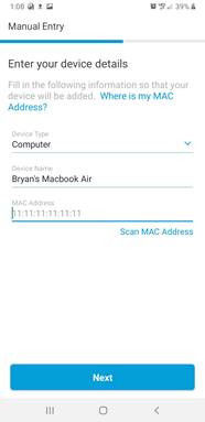
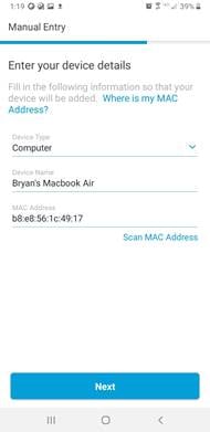
Step 4. Enter the MAC address manually or you can scan it in using your phones camera or a picture. Hit Next when finished.
| Tech tip |
|
|
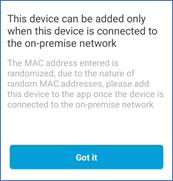 If you get a message saying the device can only be added when on-premise. It is because it is using a randomized MAC address. You can either turn off this setting if available or wait until you are on the SSID before registering. More information can be found in
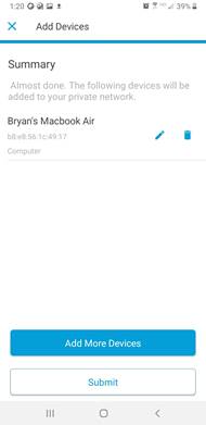
Step 5. On summary screen you can choose to go back and add more devices. If ready, click Submit to register your devices.
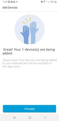
Step 6. Click Proceed.
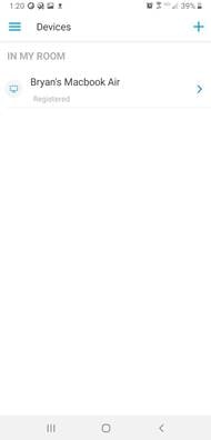
Step 7. Your device will now show up after a few seconds as registered.
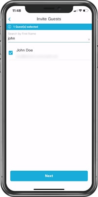
Procedure 2. Inviting Guest Users
Step 1. In the Cisco UDN application, navigate to My Guest.
Step 2. On the My Guest page, click the + in the top right corner.
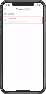
Step 3. In the search bar, start typing the name of the person you would like to invite. The person you are searching for will show up in the space below, select that user and click Next.
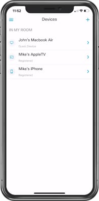
Step 4. Once accepted you will now see the invited user in the My Guests section.
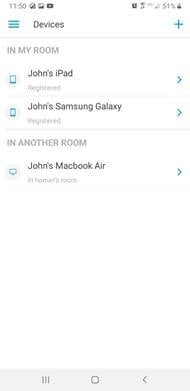
Step 5. In the Devices section, you will now see the guest devices alongside the registered devices. These devices can now communicate freely with each other.
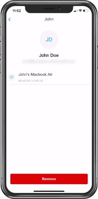
Step 6. To remove a guest user from your UDN. Select the user in the My Guests page and click Remove.
Procedure 3. Joining another user’s UDN
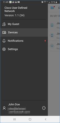
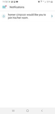
Step 1. When invited to join another user’s UDN, you will receive a notification. To view this notification, hit the menu button then click Notifications.
Step 2. Here you will see the invitation to join another room. Click the invitation and in the resulting pop up click Accept.
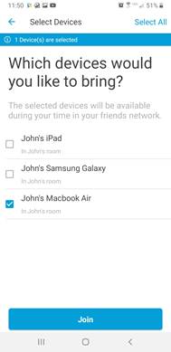
Step 3. On the next screen select the devices from your UDN you would like to bring over to the other user’s room and click Join.
Step 4. Navigate back to My Devices. Notice that the device selected in the previous step is now under In Another Room. This device can now communicate freely with devices in the other user’s room.
Process: Assurance and Troubleshooting
Procedure 1. Assurance with UDN
Step 1. Login to Cisco DNA Center and navigate to Assurance>Health.
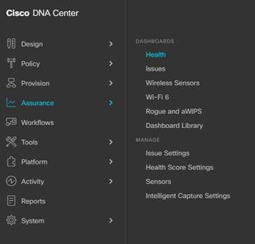
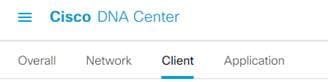
Step 2. Click Client.
Step 3. Scroll down until you see the Client Devices section.
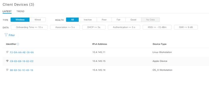
Step 4. Click on the devices MAC address you would like to know more about. This will bring us to the Client 360 page.
Step 5. Scroll down until you find the Detail Information section.
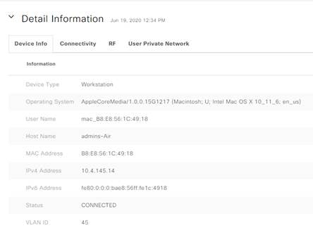
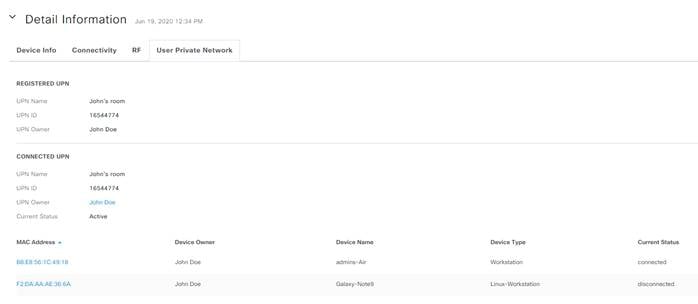
Step 6. Click the User Private Network tab. This will show you useful information including the UDN Name, Owner, UDN ID.
Step 7. Under Connected UDN we see all the other devices connected to this UDN.
Procedure 2. UDN Configuration Verification
UDN Cloud to Cisco DNA Center Trust Established
This process will verify the trust relationship between the UDN Cloud and Cisco DNA Center.
Step 1. In Cisco DNA Center, navigate to System>Settings.
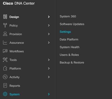
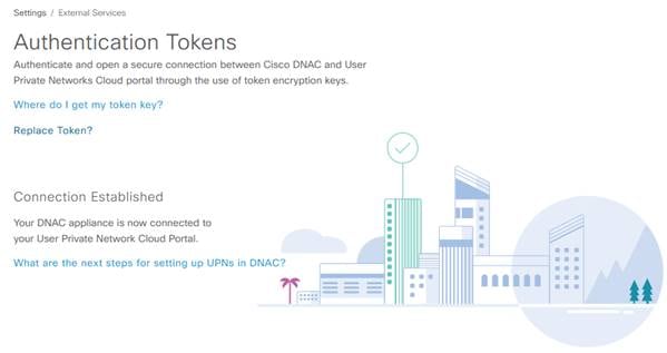
Step 2. Navigate to External Services>Authentication Tokens
Step 3. Verify the connection is established.
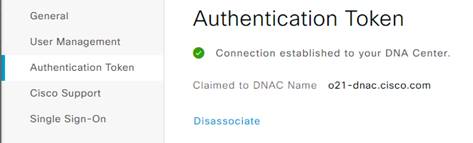
Step 4. Log in to the UDN Cloud and navigate to System>Authentication Token.
Step 5. Verify the connection is established to your Cisco DNA Center.
ISE and Cisco DNA Center PxGrid Connection
This process will verify the connection between ISE and Cisco DNA Center is up.
Step 1. Login to ISE and navigate to Administration>pxGrid Services.
Step 2. Under All Clients, see that your Cisco DNA Center subscriber name shows up.
| Tech tip |
| Note that this is showing up as Offline, this is expected as newer Cisco DNA Centers are using PxGrid v2. |
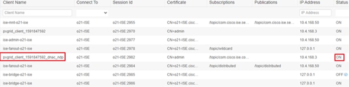
Step 3. Click the Web Clients tab.
Step 4. See that your Cisco DNA Center subscriber name shows up and the status here is ON.
ISE Policy for UDN
This process will verify the UDN Authorization Profile has been pushed.
Step 1. Login to ISE and navigate to Policy>Policy Sets.
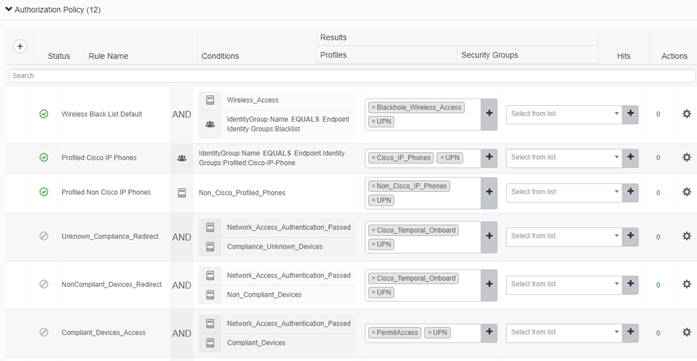
Step 2. Click the > next to your Policy Sets and click to expand the Authorization Policy.
Step 3. Check to see that the UDN Authorization Profile has been pushed to every policy rule.
UDN Enabled on Catalyst 9800
This process will verify the UDN configuration has been pushed to the Catalyst 9800.
| Tech tip |
| An AP must be attached to the Catalyst 9800 for this process to show up. |
Step 1. Login to the Catalyst 9800 WLC.
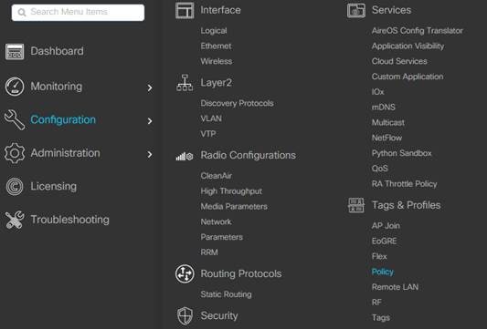
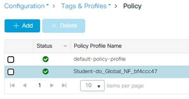
Step 2. Navigate to Configuration>Tags & Profiles>Policy.
Step 3. Click the Policy Profile used for UDN.
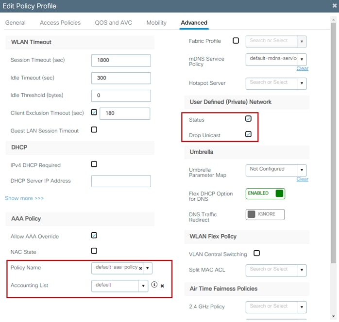
Step 4. Under the Advanced tab check to make sure the UDN Status box is checked and optionally, Drop Unicast if selected earlier during the Cisco DNA Center UDN workflow. Also, make sure that under AAA Policy the Policy Name is set to default-aaa-policy and that Accounting List is set to default.
| Tech tip |
| The Account List setting is necessary for both WPA2 Enterprise and PSK for CoA to function correctly at the WLC for UDN enabled WLANs. Normally with PSK it is not necessary to make use of RADIUS accounting, however, for CoA to function correctly during a room change for a registered UDN device, the default list must be specified. |
Procedure 3. Troubleshooting Commands
This section will go over useful commands when troubleshooting UDN.
Catalyst 9800 Wireless LAN Controller
These commands will be run on the Catalyst 9800.
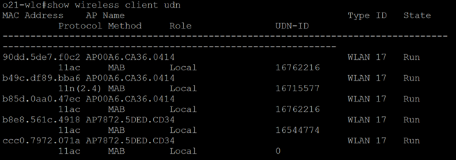
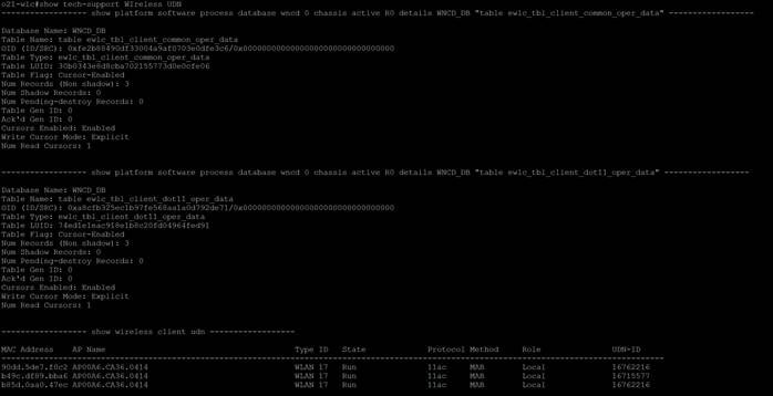
show wireless client udn
This command will show all the clients currently connected and which UDN they are connected to.
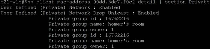
show wireless client mac-address <mac address> detail | section Private
This command can be used to see details on a certain MAC-Address.
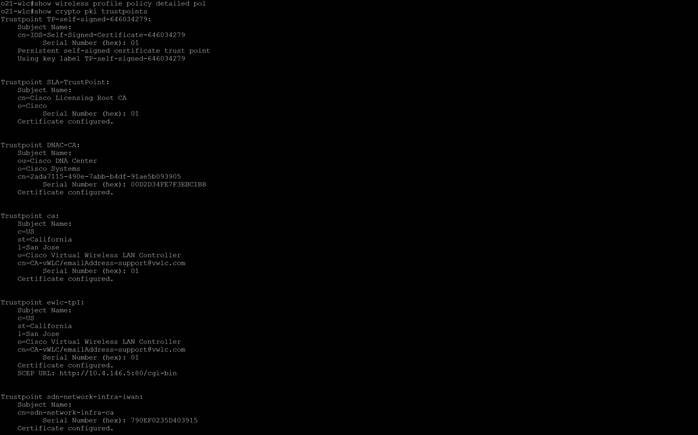
show crypto pki trustpoints
This command can be used to verify the Certificates are present.
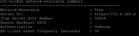
show network-assurance summary
This command can be used to verify assurance connectivity.
show telemetry internal connection
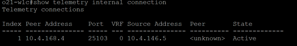
show wireless profile policy detailed <profile-name> | include User
This command can be used to verify the policy profile is pushed and UDN is enabled.
![]()
show tech-support wireless udn
This command shows a ton of useful information when troubleshooting.
ISE
This section will provide troubleshooting information for Cisco ISE.
Turning on UDN logging on Cisco ISE.
Before we can view the UDN Logs, we must first turn logging on.
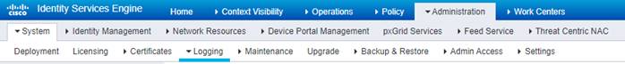
Step 1. On ISE, Navigate to Administration>System>Logging.
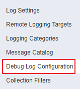
Step 2. Select Debug Log Configuration.
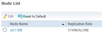
Step 3. Select your Node from the list.
Step 4. Scroll down on the list until you see UPN under Component Name.
Step 5. Change the log level of UPN to DEBUG and click Save.
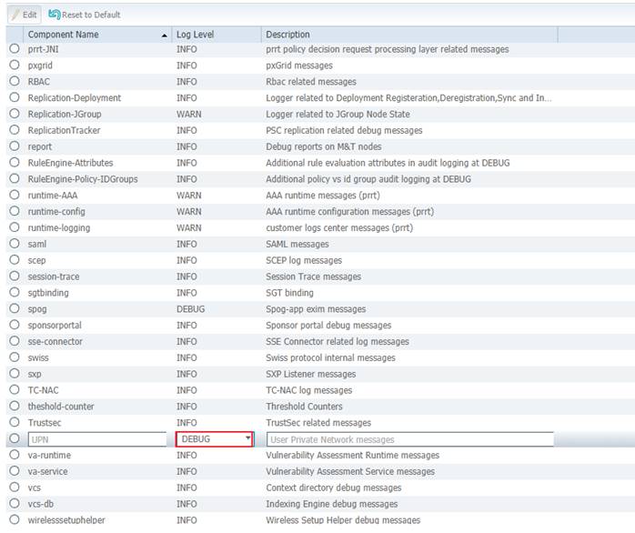
| Tech tip |
| The name UPN will be changed to UDN in future releases. |
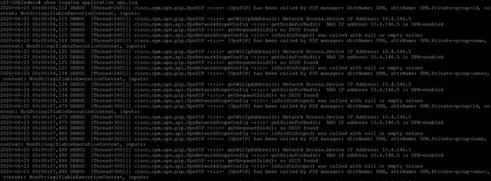
Step 6. Now that we have logging on, we can now view the logs by accessing the ISE console and entering the command show logging application upn.log.
ISE Live Logs
Operations>RADIUS>Live Logs
Successful authentication of a registered device:
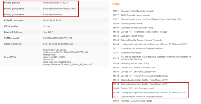
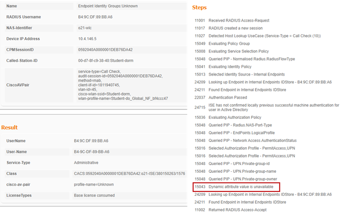
Successful authentication of an unregistered device:
Device registration CoA:
Appendix A: Configuring mDNS Gateway
Cisco's Service Discovery Gateway, or mDNS Gateway, allows for controlled and secure access to services and devices across subnets. It listens to service announcements on all configured network segments and builds a cache of services and addresses. It proxies these requests to other segments and can also apply filters based on various service attributes. These filters can limit what services will be requested or advertised.
| Tech tip |
| The mDNS Gateway feature on the Catalyst 9800 controller is incompatible with other Cisco solutions such as DNA Services for Bonjour or Wide Area Bonjour implemented at Cisco DNA Center. It should only be used in settings where these other services haven’t been implemented. |
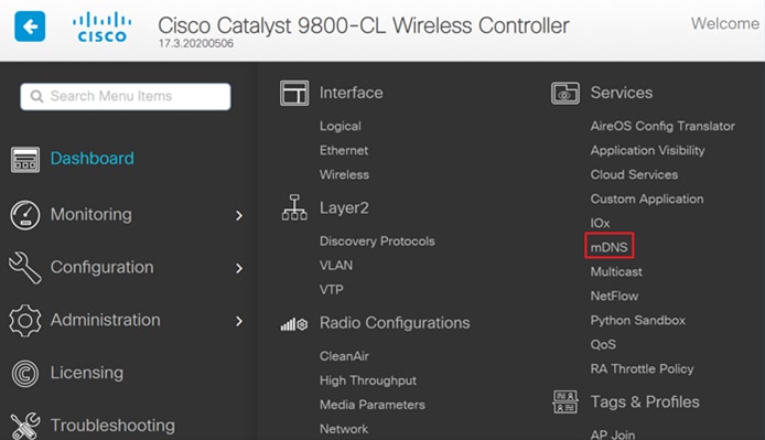
Step 1. In the Catalyst 9800 WLC, navigate to Configuration>Services>mDNS.
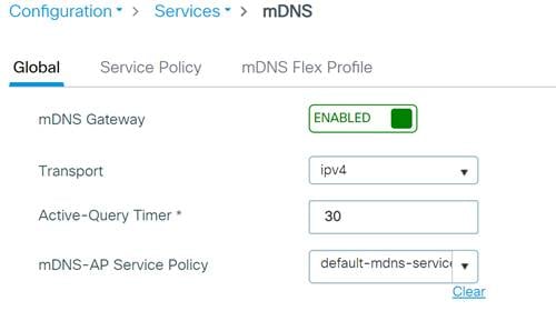
Step 2. Under Global, click next to mDNS Gateway to enable and click Apply. If running IPv6 change the Transport setting to Both.
Step 3. Navigate to Configuration>Tags & Profiles>WLANs.
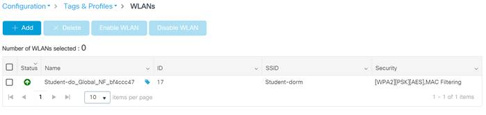
Step 4. Select the WLAN profile on which to enable mDNS gateway functionality.
Step 5. Select the Advanced tab and change mDNS Mode dropdown to Gateway. Click Update & Apply when finished.
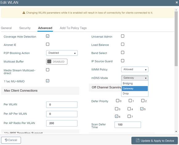
Step 6. These steps enable the default-mdns-service-policy on the WLAN with following services:
airplay, airtunes, homesharing, printer-ipp, printer-lpd, printer-ipps, printer-socket, google-chromecast, itune-wireless-devicesharing
| Tech tip |
| The Cisco UDN solution does not solve the problem of Universal Plug and Play (UPnP) across VLANs. |
Appendix B: Randomized MAC Address
MAC Addresses are being used to track and log users in public spaces, this data is then used for marketing purposes or sold to third parties. To combat this, device manufacturers have implemented random MAC addresses. This makes the user MAC address unique per network making companies unable to track the device. The address is kept consistent per network, meaning once associated with an SSID it will not have to authenticate again. This is why when using a device with random MAC address with UDN you must be on the UDN SSID before registering the device.
Appendix C: Disabling Airplay Discovery/Streaming via Bluetooth®
By default, Apple TV has AirPlay enabled with discovery via mDNS and streaming over Ethernet or wireless networks as well as Bluetooth. In a home, these setting are optimal for easy connectivity. However, in an environment such as university dormitories, hospitals, and long term healthcare facilities as an example, these default settings will allow other people to not only discover but stream to your Apple TV as well if they are on the same wired or wireless network or within 30 feet of the device in the case of Bluetooth.
When deploying Cisco UDN, discovery and streaming is limited to registered devices within the UDN for wired and wireless devices such as MacBooks, iPhones, and iPads. For the Apple TV, if the AirPlay settings are left in their default state however, devices with Bluetooth enabled and within roughly 30 feet of the Apple TV, the signal distance for Bluetooth Low Energy (BLE), will still be able to discover and stream to an Apple TV registered within a UDN. The outcome, if Bluetooth is left enabled, will be that devices in adjacent rooms both horizontally and vertically would likely be able to communicate with the Apple TV.
As the concept of Cisco UDN is to optimize the user experience by displaying only those AirPlay devices within the UDN, it might be optimal for the organization deploying the solution to recommend that Apple TVs have Bluetooth disabled by their owners when installing them in their rooms. Unfortunately, there is no single button/setting to disable Bluetooth on the Apple TV and so the following procedure details how this is accomplished.
4. From the Apple TV home screen select Settings.

5. Select AirPlay and HomeKit.
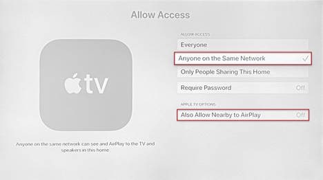
6. Select Allow Access (Default is Everyone).
7. Change from Everyone to Anyone on the Same Network
8. An Apple TV Options box appears in which you need to change Also Allow Nearby to AirPlay to Off.
For comments and suggestions about this guide and related guides, join the discussion on Cisco Community at https://cs.co/en-cvds.