Cloud Fabric Cisco Validated Case Study
Available Languages
Bias-Free Language
The documentation set for this product strives to use bias-free language. For the purposes of this documentation set, bias-free is defined as language that does not imply discrimination based on age, disability, gender, racial identity, ethnic identity, sexual orientation, socioeconomic status, and intersectionality. Exceptions may be present in the documentation due to language that is hardcoded in the user interfaces of the product software, language used based on RFP documentation, or language that is used by a referenced third-party product. Learn more about how Cisco is using Inclusive Language.
- US/Canada 800-553-2447
- Worldwide Support Phone Numbers
- All Tools
 Feedback
 Feedback
Cisco Cloud Fabric is a SaaS-based, cloud-managed campus fabric solution that enables organizations to deploy and operate a BGP EVPN VXLAN architecture through the Meraki Dashboard UI. Fabric configurations are orchestrated from the cloud, eliminating complex manual CLI deployment while combining new capabilities such as Routed Ports, VRFs, and cloud CLI with Meraki’s established onboarding, orchestration, and lifecycle management framework. The result brings operational simplicity and automation to a traditionally complex campus fabric environment while maintaining Cisco’s proven Layer 3 design principles.
This design guide presents the Validated Campus Fabric Deployment, a three-tier spine-and-leaf architecture with a Layer 3 routed underlay, VXLAN-based overlays, MP-BGP EVPN control-plane routing, and VRF-based macro segmentation. The validated design incorporates redundant spines and borders, dynamic routing using OSPF and BGP, and VRF-aware upstream handoff devices to preserve segmentation beyond the fabric boundary. Phase 1 establishes the foundational components of the fabric, including the routed underlay, scalable overlays, automated eBGP border peering, and resilient convergence to support predictable and scalable growth.
The guide details key architectural considerations and cloud-based workflows for underlay conversion, overlay provisioning, access integration, wireless deployment models, DHCP design, Adaptive Policy/Trustsec, and multi-VRF segmentation. It is intended for network architects, design engineers, implementation teams, and technical leaders responsible for planning, deploying, and operating modern campus networks, and assumes familiarity with enterprise campus networking concepts.
Enterprise campus network evolution
Over the past two decades, the enterprise campus network has evolved significantly in response to changing business requirements, technological advancements, and rising user expectations. Traditional hierarchical, tiered designs were effective in their time but have given way to modern fabric-based architectures better suited to today’s digital business environment. Fabric architectures leverage overlay technologies, automation, and policy-driven segmentation to deliver scalable, secure, and flexible networks that support mobility, cloud integration, and real-time applications. This progression represents a shift from static, manually configured infrastructures to dynamic, intent-based networks that align more closely with organizational objectives and operational demands.
Traditional architecture
Traditional enterprise campus networks have historically followed a hierarchical, three-tier architecture composed of three distinct layers:
● The access layer connects end devices such as computers, phones, and wireless access points.
● The distribution layer aggregates access switches and enforces boundary policies for routing, filtering, and QoS.
● The core layer provides high-speed, resilient transport between distribution blocks and centralized resources such as data centers and internet edge services.
While this model delivered clear separation of functions and operational scalability for many years, evolving business and application requirements have exposed some limitations:
● Operational complexity managing VLANs and spanning tree protocols across large Layer 2 domains.
● Scalability constraints with the often limited size of Layer 2 domains due to spanning tree and broadcast domain issues.
● Slow convergence during failures and recover can impact real-time applications.
● Limited flexibility with networks changes that require manual reconfiguration can be disruptive.
Drivers for evolution
Several factors have driven the evolution from traditional hierarchical campus designs to modern fabric-based architectures. Organizations increasingly depend on business-critical applications that demand high availability and rapid convergence in the event of failures. As real-time collaboration tools, voice, and video workloads have become essential to daily operations, slow failover and recovery times are not acceptable in campus environments.
At the same time, bandwidth and capacity requirements have grown exponentially due to the increase of wireless devices, high-definition video, rich media applications, and IoT endpoints. Traditional Layer 2 designs don’t always scale efficiently under these demands. Security requirements have also intensified, with evolving threat landscapes and regulatory pressures driving granular segmentation, identity-based access control, and consistent policy enforcement requirements across the network.
User mobility and operational agility also accelerate this shift. Modern enterprises require seamless connectivity for users and devices moving across campuses, with policies that remain consistent regardless of physical attachment point. Organizations are looking to simplify operations through automation and orchestration to reduce manual configuration, minimize human error, and accelerate deployment timelines. Additionally, campus networks need to integrate more tightly with virtualized environments and cloud services to support hybrid application architectures and extend segmentation and policy models beyond the traditional campus boundary.
Campus fabric emergence
Fabric architectures represent a shift from hierarchical, manually configured networks to automated, policy-driven overlays that abstract the underlying physical infrastructure. Rather than relying on large Layer 2 domains and device-by-device configuration, fabric designs separate the transport underlay from the logical overlay, enabling greater scalability, flexibility, and operational consistency.
At the foundation of this approach are overlay networks built using technologies such as VXLAN with a BGP EVPN control plane. These technologies create virtualized Layer 2 and Layer 3 networks over a routed Layer 3 underlay, allowing segmentation and mobility without redesigning the physical topology. Centralized control and automation platforms streamline provisioning, enforce policy, and provide operational assurance through a single management interface.
Fabric architectures also introduce policy-based segmentation, where software-defined constructs such as Scalable Group Tags (SGTs) enable micro-segmentation and dynamic security enforcement independent of traditional IP addressing schemes. The physical topology is simplified through spine-leaf or fabric designs that reduce complexity while improving performance and scalability. Wired and wireless networks are unified under consistent policy and visibility frameworks that ensure seamless user experiences across access methods. These capabilities deliver high availability, rapid convergence, and resilient services necessary for modern enterprise demands.
Key technologies and concepts
Software-defined access (SD-Access): An implementation of fabric-based architecture that automates campus network provisioning and policy enforcement through intent-based networking principles. By abstracting policy from individual device configuration, SD-Access streamlines deployment and aligns network behavior with defined business outcomes.
VXLAN with BGP EVPN: An overlay technology that delivers scalable Layer 2 and Layer 3 virtualization across a routed underlay. VXLAN encapsulation combined with a BGP EVPN control plane enables flexible segmentation, multi-tenancy, and efficient distribution of endpoint reachability information.
Fabric edge, intermediate, and border nodes: Distinct device roles within the fabric that define how traffic is encapsulated, transported, and exchanged with external networks. Edge nodes provide endpoint connectivity and VXLAN tunnel termination, intermediate nodes support underlay transport, and border nodes enable controlled integration between the fabric and external domains.
Centralized management: Management platforms such as Cisco Catalyst Center (formerly Cisco DNA Center) provide unified visibility and control across the fabric lifecycle. These tools support design, provisioning, policy enforcement, monitoring, and assurance through a consolidated operational interface.
Fabric architecture benefits
Fabric architectures enhance operational efficiency by automating provisioning, segmentation, and policy enforcement, reducing manual configuration effort and minimizing the risk of human error. This streamlined approach simplifies operations while maintaining architectural consistency across the campus.
They are designed to scale and support growing numbers of devices, users, and applications through flexible segmentation models that are independent of the physical topology. As demands increase, additional capacity and logical networks can be introduced without requiring disruptive redesign.
Security is strengthened through dynamic, identity-based policies that enable granular segmentation and consistent enforcement across wired and wireless domains. Faster convergence and predictable routing behavior improve overall user experience and application performance. By decoupling transport from policy, fabric architectures also provide a flexible foundation for IPv6 adoption, cloud integration, and future application requirements.
Cisco cloud fabric deployment overview
Cisco Cloud Fabric is a SaaS-based, cloud-managed campus fabric architecture that combines a Layer 3 routed underlay with a BGP EVPN VXLAN overlay to deliver scalable segmentation, rapid convergence, and operational simplicity. The validated design follows a two-tier model with combined border-on-spine nodes and leaf nodes. OSPF provides deterministic IP transport across point-to-point routed links in the underlay, while MP-BGP EVPN distributes endpoint reachability, and VXLAN encapsulates overlay traffic. VRFs enable macro segmentation, and Adaptive Policy with SGT propagation supports identity-based micro-segmentation across wired and wireless domains.
Border nodes provide dynamic eBGP integration with upstream networks, preserving segmentation beyond the fabric edge in recommended VRF-aware deployments. All fabric configurations, including underlay parameters, overlay subnets, VRFs, and eBGP peering, are orchestrated through the Meraki Dashboard workflow, eliminating complex manual CLI configuration while maintaining Cisco enterprise design best practices. The result is a resilient, scalable campus architecture that unifies transport, segmentation, and policy under centralized cloud management.
Architectural framework
To provide a consistent architectural framework, the solution aligns with a 5-layer Secure Network Reference Architecture (SNRA) model. This model organizes the design into functional layers that map directly to how the fabric is built, secured, operated, and extended. Rather than introducing separate constructs, the SNRA model exposes how each component of the Cloud Fabric participates in a cohesive system.
The SNRA Architecture Model consists of these five layers:
Layer 1-Secure Network Infrastructure: Physical and routed foundation of the fabric, including spine-leaf topology, OSPF underlay, and resilient transport.
Layer 2-Scalable Network Segmentation: Logical segmentation using EVPN VXLAN and VRFs to isolate traffic and enable scalable multi-domain design.
Layer 3-Zero Trust Access & Hybrid Mesh Firewall: Identity-based access control using Adaptive Policy and SGTs to enforce consistent policy across wired and wireless users.
Layer 4-Unified Management & Agentic Operations: Centralized cloud management via the Meraki Dashboard for automated provisioning, policy orchestration, and lifecycle operations.
Layer 5-Extended Integration: Integration with external networks, data centers, and third-party systems through border nodes, APIs, and cloud-based extensibility.
By aligning the Cloud Fabric architecture to the SNRA 5-layer model, this design makes it clear how transport, segmentation, policy, operations, and integration are not separate elements, but interdependent layers of a single system. Each layer builds on the one below it, creating a campus fabric that is not only scalable and resilient, but also operationally consistent and aligned to modern Zero Trust and cloud-managed networking principles. To learn more review Secure Networking Overview.
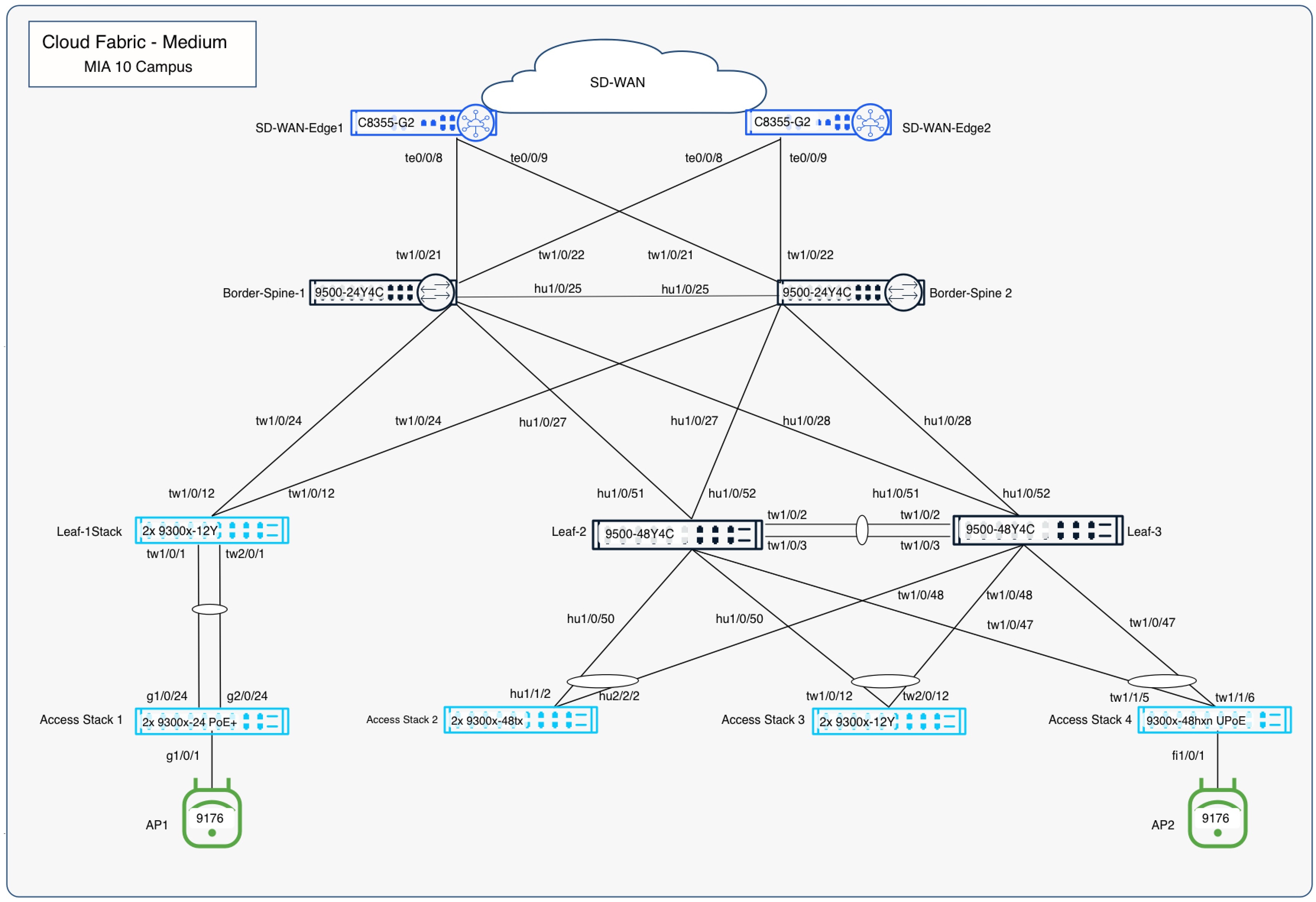
In this validated use case, a three-tier spine-and-leaf campus fabric deploys with redundant spines, leaves, and dedicated border devices. A Layer 3 routed underlay using OSPF provides fast convergence and predictable connectivity, while VXLAN overlays deliver scalable segmentation across multiple VRFs. Border devices use automated eBGP peering to integrate the fabric with upstream networks, maintaining VRF separation beyond the fabric edge.
This approach allows Cisco customers to:
● Simplify campus fabric deployment through UI-driven workflows
● Reduce operational risk by eliminating manual overlay CLI configuration
● Maintain Cisco-recommended Layer 3 design best practices
● Scale segmentation using VRFs without redesigning the physical network
● Integrate access, wireless, DHCP, and Adaptive Policy/Trustsec consistently across the fabric
The validated design demonstrates how Cisco Cloud Fabric enables network architects and operators to deploy and operate a modern campus fabric that combines the architectural rigor of traditional Cisco campus designs with the simplicity and automation of cloud-managed operations, all while remaining aligned with Cisco enterprise networking standards and lifecycle practices.
Validated case studies
Cisco Cloud Fabric supports designs with dedicated border devices and border-on-spine deployments (border-on-leaf is not currently supported). The upstream devices that connect to the borders may vary in capabilities resulting in design differences.
This document references a border-on-spine case study that follows best practice recommendations using redundant borders and redundant upstream handoff devices.
Border-on-spine topology
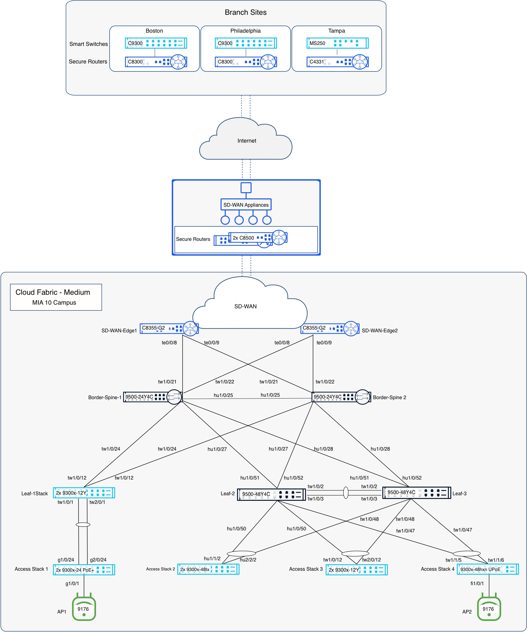
This case study uses a pair of Catalyst SD-WAN edge devices in an active/active configuration. OSPF is used between the handoff devices and the borders for dynamic underlay routing, and eBGP is used between the borders and the handoff devices for dynamic overlay routing. VRF separation is maintained to and beyond the handoff devices, with a fusion device routed further upstream. This is the recommended deployment option and, as such, is detailed in this document.
In this case study, the links between the borders and the handoff devices are IEEE 802.1Q trunks. These trunks carry both underlay and overlay traffic. For overlay routing, eBGP is used, and the configurations are automated on the border side as part of the fabric workflow. In typical fabric networks, the underlay IGP is redistributed into BGP on the borders, and eBGP is also used for underlay routing between the borders and the handoff devices, typically in a VRF-Lite handoff when the handoff devices are VRF-aware. However, redistribution from OSPF into BGP is not currently available on the switches. As a result, the available options are static routing or extending OSPF from the underlay to the handoff devices. The validated setup uses OSPF due to its dynamic nature.
Architectural foundations
Fabrics - Fabrics are built using an underlay and overlay model.
Fabric Device Roles – Fabrics are typically deployed following a Clos architecture using a spine-and-leaf approach. The Cisco Cloud Fabric architecture uses a three-tier model similar to traditional Core–Distribution–Access layer designs, with spines at the core, leaves at the distribution layer, and traditional switches and Access Points at the access layer. The border function is deployed on a limited number of devices within the fabric to connect the fabric to external networks. Cisco Cloud Fabric supports both dedicated border deployments and border-on-spine deployments.
Fabric Underlay - In campus fabric environments, the underlay uses an IGP with Layer 3 point-to-point links to eliminate spanning tree, enable rapid convergence, and support equal-cost multi-pathing (ECMP). Cisco Cloud Fabric uses Routed Ports and OSPF to establish underlay reachability. The fabric control plane runs MP-BGP EVPN (AFI 25 / SAFI 70) over the underlay to distribute overlay endpoint reachability, with BGP peering established using OSPF reachability. The data plane uses VXLAN encapsulation to transport overlay traffic. The underlay is manually configured in the current Cisco Cloud Fabric solution. The fabric underlay connects to external handoff devices through border nodes using OSPF routing.
Fabric Overlay(s) – An overlay is a logical network in which traffic is encapsulated and transported between underlay devices. Cisco Cloud Fabric uses IP-based underlay packets sourced and destined to devices within the underlay routing domain, with overlay traffic carried using VXLAN encapsulation. Virtual Network Identifier (VNI) and Security Group Tag (SGT) information is conveyed in the VXLAN header. VRFs define logical overlays on fabric devices, including leaves and borders, where VXLAN tunnels terminate. Fabric borders use eBGP for dynamic routing into and out of overlay networks. Overlay eBGP peering on fabric borders toward external handoff devices is fully automated, while external handoff devices are manually configured to interoperate.
Solution considerations
Handoff considerations
The border role must be present on at least one fabric device to connect the fabric to the outside world. Fabrics are typically configured with two borders for high availability. As stated in the Case Study Context section, Cisco Cloud Fabric supports designs with dedicated border devices and border-on-spine deployments (border-on-leaf is not currently supported). In either case, one or more upstream devices are required at the other end of the border handoff.
DHCP considerations
When the Cisco Cloud Fabric creates fabric overlay subnets, DHCP is automatically configured to relay requests to external DHCP servers. These relayed packets are sourced from an underlay loopback address on the fabric leaf where the requesting client’s IP gateway resides. As a result, IP reachability is required from the DHCP infrastructure outside the fabric environment to the underlay loopback range inside the fabric, and the DHCP infrastructure must be VRF-aware.
Meraki device default behavior
In Meraki cloud-controlled mode, the default device configuration sets all ports as trunks with VLAN 1 configured as the native VLAN. The devices will attempt to obtain IP and DNS settings via DHCP and connect to the Meraki Cloud for configuration and management.
Best of breed hardware
Many modern Cisco switches and wireless devices can be configured locally or from the Meraki cloud. The supported hardware models can be switched between modes as required. The Cloud Fabric solution requires that device configurations are controlled by the Cloud. If existing catalyst switches are running 17.15.n and are Meraki-monitored with locally controlled CLI, they must be removed from their current Meraki network. Once the cloud-driven cleanup scripts complete, upgrade the switches to 17.18.2, and re-add them to the target Meraki network where the fabric will be created.
Note: When adding them back into that network, the option for them to be cloud-managed must be selected. The devices do not need to be unclaimed and reclaimed; they only need to be removed and re-added to the Meraki network.
Cloud reachability considerations
In environments where additional cabling and IP reachability to the Meraki Cloud infrastructure is available, it is convenient to use that for device to cloud management communications. Currently, this requires the use of additional “front panel” ports to connect to the dedicated cabling, and that IP connectivity and related routing is in the global routing table of the managed devices. In the Cisco Cloud Fabric solution, the UAC (Uplink Autoconfigure) and the resulting IP connectivity to the cloud-delivered control plane are in-band in the fabric underlay network. This validated deployment does not use additional dedicated cables for UAC traffic. This is relevant during the conversion from the default Layer 2 trunks to the recommended Layer 3 routed connections between the devices that will become fabric devices.
Note: It is important not to break UAC management's connectivity to the cloud during that conversion. Dedicated management cabling makes that simpler but is not always an option.
Fabric design best practices
The Cisco Cloud Fabric solution is based on a 3-tier architecture with access layer routing occurring at SVIs configured on the fabric leaves at tier-2. The leaf routing can be deployed in one of three ways:
In order of preference
1. Routed SVI on leaf with unique subnet(s) per leaf
2. Routed SVI on leaf as Distributed Anycast Gateway (DAG) - same subnet on multiple leaves
3. Routed SVI on leaf as DAG with bridging - same subnet and bridging on multiple leaves
The ideal situation will have unique subnets deployed off each leaf which does not require a DAG. This approach provides the greatest scalability and is preferred whenever possible. When the same subnet is required on multiple leaves, a DAG routed configuration is used, and when bridging is required, a DAG bridged configuration is used. These options can be combined within a fabric; however, Cisco best practice is to route unique subnets and use DAG routed or DAG bridged designs only when necessary, minimizing the use of less preferred options. These best-practice recommendations are based on years of large-scale campus fabric customer deployment experience.
One additional Cisco best practice recommendation is to use a Layer 3 routed underlay, which currently requires some manual configuration. Layer 2 trunks, STP and SVIs can be used and may be advantageous in some brownfield migration scenarios, particularly when no spare cabling exists between fabric devices. However, a Layer 3 underlay is the preferred and proven approach with years of customer proven scalability and reliability and should always be the target end state.
Dot1x/Trustsec/Adaptive policy
Cloud-provisioned 802.1X authentication for wired and wireless access is supported, along with dynamic VLAN assignment (by name or number) and filter-list assignment. Micro-segmentation using SGTs, including dynamic classification during 802.1X authentication, SGT propagation via Cisco Metadata Header and/or AutoVPN, and egress enforcement, is provided through Meraki Adaptive Policy on supported platforms. Because Cisco Cloud Fabric does not alter the access layer architecture, these capabilities remain fully supported and unchanged.
Trunks between the access layer and fabric leaves can be configured for inline tagging using the Peer SGT Capable option. SGTs are preserved for overlay traffic, as they are carried in the VXLAN header across the fabric, and can optionally be propagated through the border using inline tagging.
Note: Border handoffs must be trunks with SVIs. The option to include the CMD header on routed port traffic is not currently supported, and the automation assumes the handoff links are trunks with SVIs.
Access layer to leaf EtherChannel
In Cisco Cloud Fabric, the access layer devices are not fabric-aware and operate unchanged and typically have trunks connecting to their upstream device. In a Cloud Fabric, the upstream device is a leaf that acts as the fabric edge and functions as a VXLAN Tunnel Endpoint (VTEP); border nodes also operate as VTEPs. EtherChannels are supported between access layer devices and their upstream leaf to provide increased bandwidth and redundancy.
Multi-homing design considerations
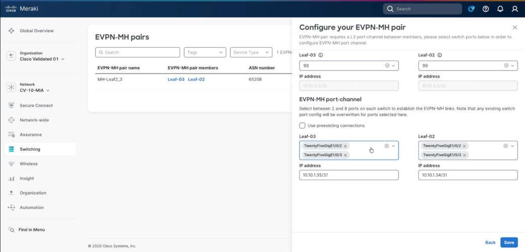
In the SNRA Cloud Fabric architecture, EVPN Multi-homing provides redundant Layer 2 connectivity from non-fabric access switches or access switch stacks to a pair of fabric leaf nodes using a single logical port channel. This design allows traditional access layer infrastructure to connect into the cloud-managed EVPN VXLAN fabric without participating in the overlay control plane, while the fabric leaf nodes provide VXLAN tunnel termination and policy integration. Multi-homing is used when access layer devices require resilient uplinks into the fabric without relying on a single leaf connection or extending spanning-tree dependency across the fabric. This improves access layer availability, supports predictable failure recovery, and aligns with the SNRA Cloud Fabric goal of combining Layer 3 routed fabric principles with practical brownfield access integration. This architecture provides redundancy to the access layer switches while providing active/active forwarding.
Access layer to leaf high availability
High availability for access devices connecting to fabric leaves is provided through Multi-Chassis EtherChannel (MEC). Back-panel stacking forms a leaf stack, with multiple links from different stack members to the access device bundled into an EtherChannel using the aggregate function in the UI. This can be to a single access switch or an access switch stack providing even greater redundancy with a stack on both ends of the connection. Currently, an access device can only be connected to a single leaf or leaf stack.
MTU considerations
The UI defaults the system MTU to 9198, which maps to the system MTU command; however, the recommended best practice is an MTU of 9100, configured at the network level and applied to all switches in the network.
Note: All the devices at a given site are grouped together and referred to as a single network in the UI.
Fabric automation configures EBGP peer SVIs with an IP MTU of 9100 by default, which can be overridden if required. External devices connected to border nodes must be configured with matching MTUs for both underlay and overlay traffic. With an MTU of 9100, underlay traffic remains unfragmented up to 9100 bytes, while IPv4 VXLAN encapsulation adds 50 bytes of overhead, allowing unfragmented overlay payloads up to 9050 bytes.
Spanning tree considerations
Meraki deploys Multiple Spanning Tree (MST) by default. The best practice recommendation for Cisco Cloud Fabric is to use Rapid Per VLAN Spanning Tree (RPVST+). STP is configured at the network level in the UI, ensuring all switches at a site use the same STP version; this is part of the Layer 3 underlay preparation performed before running the fabric workflow.
Note: Care must be taken when changing this setting so as not to disrupt UAC connectivity.
The Routed Underlay deployment steps in this document provide guidance for this configuration. During the Layer 3 underlay conversion process, RPVST+ is enabled; spine bridge priorities are set to 4096 (spine1) and 8192 (spine2), and most interfaces are shut down with remaining trunks tightly restricted. After migration, STP no longer runs between fabric nodes, and leaf bridge priorities are set to 0, resulting in a leaf being the root bridge for accessing VLANs on the trunks to the downstream access devices.
● Unique routed subnets per leaf - Using unique routed subnets in each leaf, as recommended best practice, clients are required to obtain a new IP address when roaming between APs on different leaves. An SSID may bridge to the same VLAN name or number; however, the VLAN represents a unique broadcast domain on each leaf. For clarity, fabric VLAN 100 (leaf1) is a separate broadcast domain and subnet from VLAN 100 (leaf2). This design is best suited for deployments where a leaf or leaf stack serves a single building or space, and seamless wireless coverage between buildings or spaces is not required.
● Common subnet on two or more leaves - When seamless roaming is required between buildings or spaces with contiguous wireless coverage, a routed DAG is used. This design routes the same IP subnet on multiple leaves, with each participating leaf using the same VLAN number and the SSID bridging to that VLAN. As a client roams between APs on different leaves, the client's IP address remains unchanged. The upstream fabric detects client movement and updates routing to forward traffic to the new servicing leaf, effectively enabling a fabric leaf roam.
● Bridging is required - When bridging is also required, the routed DAG could include the bridge option and thus become a bridged DAG. This is the least preferred deployment option and should only be used when necessary and judiciously.
Deployment prerequisites and considerations
The following information should be gathered in advance of any configuration work.
Underlay network IP and VLAN
Allocate sufficient IP address space accounting for the following:
● Underlay point to point links - Each leaf connects to each spine; the spines connect to each other, and if dedicated borders are used, each border connects to each spine. Additionally, the border handoff links must be considered in the underlay design. Links between fabric devices are converted to Layer 3 links, and /31 subnets are recommended. The links from the borders to the handoff devices remain trunks, only carry specific underlay and overlay VLANs, and function as routed interconnects using SVIs.
● Underlay IP address range entered during the fabric workflow – The automation uses IP addresses from the selected range for the underlay loopback 100 interface on each fabric device. Additional IP addresses from this range include the loopback 600 address on each spine for MSDP peering and the loopback 300 address on each spine, which is the PIM anycast RP address. Assume an additional 32 host addresses must be reserved for other infrastructure SVI IPs allocated from this pool. Ensure sufficient IP address space is provided for current and future needs, including adding new leaves.
Note: Note that changing this IP address range requires rebuilding the fabric.
● Temporary DHCP pools – Pools are used when converting fabric devices with default configurations to a Layer 3 underlay configuration. These devices initially obtain addresses via DHCP on VLAN 1 and are then manually converted to routed interconnects. In the event of an RMA or new fabric device addition, this pool or a similar temp pool must be activated to facilitate the onboarding and conversion to Layer 3 underlay. This is also necessary if a fabric device is reset to factory default settings.
● Permanent DHCP pools for access layer devices – Access layer devices are managed in VLAN 1 by default. Cisco’s best practice recommendation is to use a different VLAN. VLAN 2 was used in the Cisco Validated setup. Management traffic routes on an SVI that is manually created as part of normal setup. SVIs for access layer devices terminate on their upstream leaf, requiring a unique subnet per leaf, which must be sized to support current and future downstream devices, including switches, access points, and cameras that require UAC control-plane connectivity to the cloud.
● Optional traditional subnets and VLANs – Subnets can be routed on a leaf that is not part of the fabric, which are no different than the management network required on each leaf. Subnets must be unique per leaf and manually configured. If traditional subnets are created, they will be part of the underlay routing domain, which may be relevant in a migration scenario. And existing deployment can be migrated in stages:
◦ First to a traditional three-tier design with unique subnets per distribution switch,
◦ Then to Layer 3 links between core and distribution, and
◦ Finally, to fabric.
● Subnets can then be gradually transitioned from underlay SVI routing to fabric overlay SVI routing. If a traditional subnet is configured on a fabric leaf, a corresponding VLAN is required. The same VLAN number can be used across leaves if required, as those VLANs are discrete broadcast containers and are not connected over the routed connections between the spines and leaves. This assumes the use of a best practice Layer 3 underlay.
Note: It is ideal if all the underlay networks can be summarized into a single prefix for summarization at the handoff devices out to the rest of the Intranet.
● Underlay OSPF information – It is important to plan a unique OSPF Area number for this handoff for the underlay between the borders and handoff devices. OSPF Area 0 is used between the spines and leaves, and spines and borders. Be prepared to match the interface MTU and media type on the handoff devices. The validation setup used OSPF Area 1 between the borders and handoff devices.
● Overlay networking IP and VLAN information – The subnets and associated VLAN numbers are entered in the fabric workflow. The planning depends on the options being configured:
◦ Routed – 1 Subnet and VLAN number for each leaf selected (the VLAN number can reused if desired and can be beneficial in certain wireless scenarios)
◦ Routed DAG – 1 subnet and VLAN number per set of selected leaves
◦ Bridged DAG – 1 subnet and VLAN number per set of selected leaves
Note: Multiple instances of each option can be deployed; options may be combined in any manner, and the target leaf or leaves are selected independently for each deployment. For example, two routed subnets can be defined, with one existing only on a subset of leaves. Less-preferred DAG options should be deployed only on the leaves where they are required.
● BGP information – A new BGP AS number is required for the fabric and is specified during the fabric workflow; a private AS may be used if needed. The workflow also collects handoff device BGP details, including the remote AS number and any MD5 authentication strings to automate border eBGP configuration.
Reference deployment information
The following section documents the pre-planning details for the validated campus fabric deployment in the Cisco Validated Network in Miami (MIA10).
IP address, VLAN, and DHCP
| Subnet |
Description |
Fabric Leaf/ Leaves |
VLAN |
DHCP Server Location |
| 10.10.0.0/16 |
Assigned range for this location / network |
|
|
|
| 10.10.0.0/18 |
Underlay and any traditional access layer subnets |
|
|
|
| 10.10.0.0/24 |
Initial DHCP pool for default underlay |
|
|
WAN-Edge-01 Te0/0/8 |
| 10.10.1.0/24 |
Manually configured /31s between spines and leaves/borders and Borders Handoffs |
|
|
|
| 10.10.2.0/23 |
Underlay Subnet for Fabric workflow |
|
|
|
| 10.10.5.0/24 |
leaf-01 access layer UAC Management |
|
VLAN 2 |
leaf-01 |
| 10.10.6.0/24 |
leaf-02 access layer UAC Management |
|
VLAN 2 |
leaf-02 |
| 10.10.7.0/24 |
leaf-03 access layer UAC Management |
|
VLAN 2 |
leaf-03 |
| 10.10.21.0/24 |
leaf-01 traditional user subnet |
|
VLAN 21 |
Corp Server 10.100.0.5 via Underlay |
| 10.10.22.0/24 |
leaf-02 traditional user subnet |
|
VLAN 22 |
Corp Server 10.100.0.5 via Underlay |
| 10.10.23.0/24 |
leaf-03 traditional user subnet |
|
VLAN 23 |
Corp Server 10.100.0.5 via Underlay |
| 10.10.64.0/18 |
Overlay Range - Campus VRF |
|
|
|
| 10.10.64.0/24 |
leaf-01 routed fabric subnet - no DAG |
leaf-01 |
VLAN 200 |
Corp Server 10.100.0.5 with VRF via Underlay |
| 10.10.65.0/24 |
leaf-02 routed fabric subnet - no DAG |
leaf-02 |
VLAN 200 |
Corp Server 10.100.0.5 with VRF via Underlay |
| 10.10.66.0/24 |
leaf-03 routed fabric subnet - no DAG |
leaf-03 |
VLAN 200 |
Corp Server 10.100.0.5 with VRF via Underlay |
| 10.10.74.0/24 |
1st routed DAG fabric subnet |
leaf-01, leaf-02 |
VLAN 274 |
Corp Server 10.100.0.5 with VRF via Underlay |
| 10.10.75.0/24 |
2nd routed DAG fabric subnet |
leaf-02, leaf-03 |
VLAN 275 |
Corp Server 10.100.0.5 with VRF via Underlay |
| 10.10.84.0/24 |
1st Bridged DAG fabric subnet |
leaf-02, leaf-03 |
VLAN 284 |
Corp Server 10.100.0.5 with VRF via Underlay |
| 10.10.127.0/24 |
/31 routed interconnects for Handoff links |
|
VLANs 6-9 |
|
OSPF and BGP routing
OSPF Underlay
| WAN-Edge Description |
Border Interface |
WAN-Edge Interface Leaf/ Leaves |
VLAN SVI |
Subnet |
Trunk Interface |
OSPF Area |
MTU |
| Border-Spine-01 to WAN-Edge-01 |
10.10.1.0 |
10.10.10.1 |
VLAN 2 |
10.10.1.0/31 |
Border tw1/0/21 to WAN-Edge te0/0/8 |
1
|
9100
|
| Border-Spine-01 to WAN-Edge-02 |
10.10.10.2 |
10.10.10.3 |
VLAN 3 |
10.10.1.2/31 |
Border tw1/0/22 to WAN-Edge te0/0/8 |
1
|
9100
|
| Border-Spine-02 to WAN-Edge-01 |
10.10.10.4 |
10.10.10.5 |
VLAN 4 |
10.10.1.4/31 |
Border tw1/0/21 to WAN-Edge te0/0/9 |
1
|
9100
|
| Border-Spine-02 to WAN-Edge-02 |
10.10.10.6 |
10.10.10.7 |
VLAN 5 |
10.10.1.6/31 |
Border tw1/0/22 to WAN-Edge te0/0/9 |
1
|
9100
|
| OSPF Area Number |
Name |
Type |
| 0 |
backbone |
normal |
| 1 |
WAN-Edges |
normal |
| 11 |
leaf1 |
stub |
| 12 |
leaf2 |
stub |
| 13 |
leaf3 |
stub |
BGP (Overlay-VRF Light)
| Routing Domain |
BGP Autonomous System Number / ASN |
| External SD-WAN WAN-Edge VRFs 100,200 |
65207 |
| MIA 10 Fabric overlays |
65208 |
Guest VFR handoff
| WAN-Edge Description |
Border Interface |
WAN-Edge Interface |
VLAN SVI |
Subnet |
Trunk Interface |
OSPF Area |
MTU |
| Border-Spine-01 to WAN-Edge-01 |
10.10.127.0 |
10.10.127.1 |
VLAN 6 |
10.10.127.0/31 |
Border tw1/0/21 to WAN-Edge te0/0/8 |
C1sco12345
|
9100
|
| Border-Spine-01 to WAN-Edge-02 |
10.10.127.2 |
10.10.127.3 |
VLAN 7 |
10.10.127.2/31 |
Border tw1/0/22 to WAN-Edge te0/0/8 |
C1sco12345
|
9100
|
| Border-Spine-02 to WAN-Edge-01 |
10.10.127.4 |
10.10.127.5 |
VLAN 8 |
10.10.127.4/31 |
Border tw1/0/21 to WAN-Edge te0/0/9 |
C1sco12345
|
9100
|
| Border-Spine-02 to WAN-Edge-02 |
10.10.127.6 |
10.10.127.7 |
VLAN 9 |
10.10.127.6/31 |
Border tw1/0/22 to WAN-Edge te0/0/9 |
C1sco12345
|
9100
|
RPVST+ Spanning Tree priorities
| Fabric Device |
Bridge Priority |
VLAN List |
Notes |
| spine1 |
4096 |
1-4094 |
Just for underlay conversion and RMA or new leaf add |
| spine2 |
8192 |
1-4094 |
Just for underlay conversion and RMA or new leaf add |
| leaf1 |
0 |
2,21,200,274 |
Should match the trunk allow list between leaf and access devices |
| leaf2 |
0 |
2,22,200,274-275,284 |
Should match the trunk allow list between leaf and access devices |
| leaf3 |
0 |
2,23,200,275,284 |
Should match the trunk allow list between leaf and access devices |
Routed underlay design and deployment
The validated setup is a greenfield deployment built on top of a manually configured Layer 3 underlay. It is important to have the underlay network complete with stable routing before attempting the fabric workflow. This section outlines building the CV underlay by following recommended best practices.
Initial topology
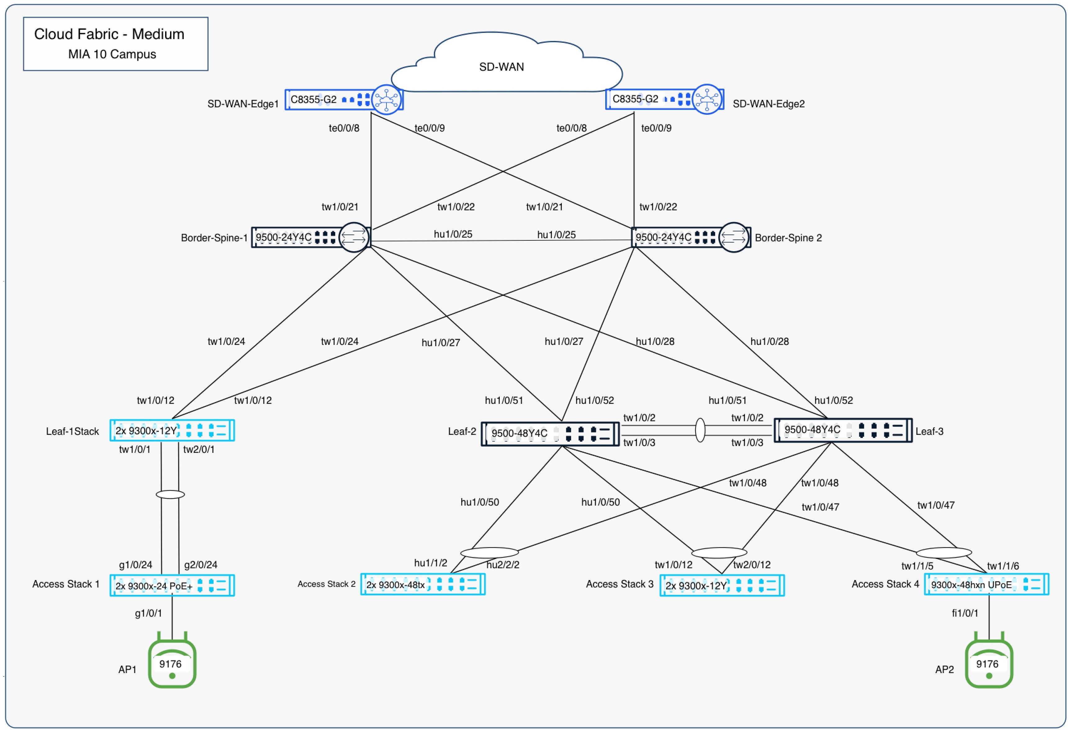
Initial setup includes all devices be in the default configuration:
● All interfaces are trunks with a native VLAN of 1 and an allowlist of 1-1000.
● All switches run MST.
● The upstream handoff devices are fully configured and out of scope in this document (their final configs are available in the appendices).
● A temporary initial DHCP pool is configured in VLAN 1 on WAN-Edge-01.
● All devices have UAC control plan management connectivity to the cloud and have been added to a network called CV-10-MIA.
● All switches running IOS-XE 17.18.2.
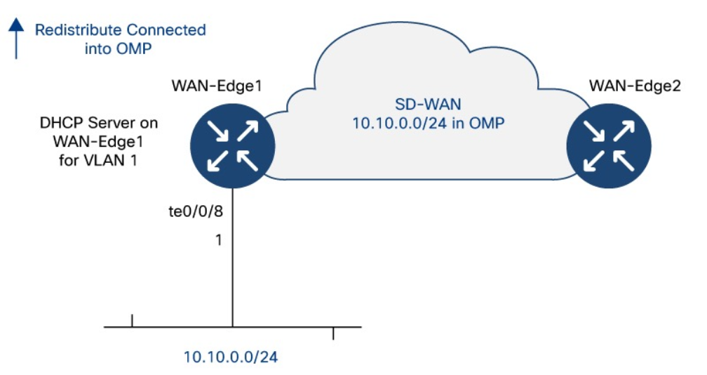
Layer 3 underlay conversion
Care must be taken when converting fabric links from Layer 2 trunks to Layer 3 routed interfaces. The process assumes a two-tier fabric topology with combined border-on-spine nodes and leaf nodes, where each leaf is redundantly connected to the border/spine layer. Each border-on-spine node provides upstream connectivity to external handoffs, ensuring consistent integration with the network edge.
This design delivers fully redundant physical paths across the fabric while maintaining alignment with a Layer 3 routed underlay using OSPF. Using an outside-in approach, begin with the handoff-to-border links and convert one side of each redundant link to Layer 3 with OSPF routing, enabling a controlled transition while preserving stability and reachability throughout the fabric.
Note: The first link being converted to Layer 3 on a given switch will automatically become the new UAC link. As links are converted from the borders to the spines and then spines to leaves, OSPF routing must provide reachability to the Internet. Once all fabric switches are using Layer 3 and OSPF routing for their UAC connectivity, the other half of the redundant links can be converted to complete the Layer 3 underlay.
The specific steps used in the validated network through the Dashboard UI are as follows:
Step 1. Adjust the Spanning Tree settings according to current planning.
Note: Before changing the settings, it is critical to shut down all ports on the leaves except for their uplinks to the spines.
Note: It is also important to then adjust the trunk allowlist on the remaining active links on all fabric devices to only include the required VLANs.
VLAN 1 is needed for temporary management. In the validation setup underlay VLANs 2-5 were required for the border to handoff trunks. The goal is to reduce the required instances of STP to the minimum required before switching to RPVST+ to avoid traffic disruptions.
1. Navigate to Switching > Switch Settings.
2. In the STP configuration section set the following parameters:
3. Select Enable Spanning Tree.
4. Select Enable Rapid Per-VLAN Spanning Tree Plus (RPVST+).
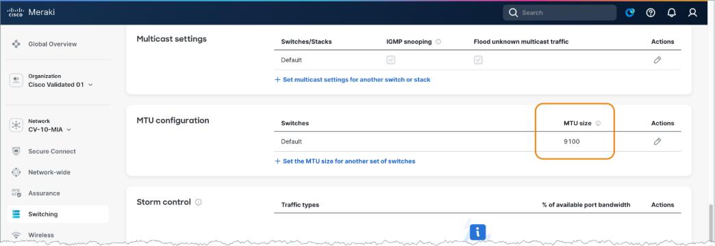
Step 2. Set the network-wide MTU value for all switches to 9100.
1. On the Switch Settings screen, scroll to MTU configuration.
2. Set the MTU Size value to 9100.
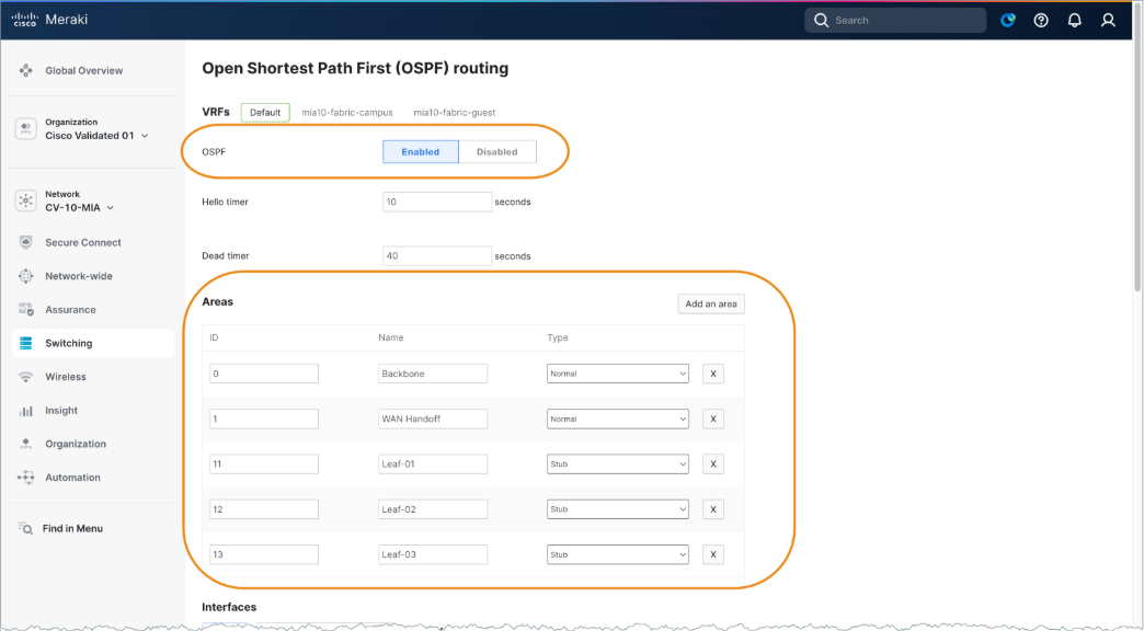
Step 3. Set the network-wide OSPF settings according to current planning.
1. Navigate to Switching > OSPF Routing.
2. Select Enabled.
3. Add the following Areas values:
| ID |
Name |
Type |
| 0 |
Backbone |
Normal |
| 1 |
WAN Handoff |
Normal |
| 11 |
Leaf-01 |
Stub |
| 12 |
Leaf-02 |
Stub |
| 13 |
Leaf-03 |
Stub |
Step 4. Identify the current uplink port on a switch to allow converting the other port.
1. Ensure the initial temporary UAC is in VLAN 1.
2. Verify there are two uplink trunks on each switch carrying VLAN 1.
3. Ensure that the link not currently used for UAC is chosen for modification.
4. Use the show uac uplink command using the Cloud CLI capability to quickly determine which link is currently used for UAC.
Note: Since the bridge priority of spine1 was set to 4096, the root port for VLAN 1 should be very predictable and that should align with the Port Used: field in the UAC display.
MIA10-Leaf-01>show uac uplink
Uplink Autoconfig: Enable
Uplink Allow-list enforce: IPV4:No IPv6:No
Configured IPv4 Uplink interface: Vlan 1 (Default)
Uplink IPv4 interface: Vlan 1
IP Address: 10.10.0.18/255.255.255.0
DHCP
SVI: Configured
Port Used: GigabitEthernet1/0/13
GW IP: 10.10.0.1
GW MAC: cc03.d9ff.5d81
Score: 7
Configured IPv6 Uplink interface: Vlan 1 (Default)
Uplink IPv6 interface: None
Uplink Reachable: IPv4
MIA10-Leaf-01>show int trunk
Port Mode Encapsulation Status Native vlan
Gi1/0/13 on 802.1q trunking 1
Gi1/0/14 on 802.1q trunking 1
Port Vlans allowed on trunk
Gi1/0/13 1
Gi1/0/14 1
Port Vlans allowed and active in management domain
Gi1/0/13 1
Gi1/0/14 1
Port Vlans in spanning tree forwarding state and not pruned
Gi1/0/13 1
Gi1/0/14 none
MIA10-Leaf-01>show span
VLAN0001
Spanning tree enabled protocol rstp
Root ID Priority 4097
Address 24d5. e41d.6300
Cost 20000
Port 13 (GigabitEthernet1/0/13)
Hello Time 2 sec Max Age 20 sec Forward Delay 15 sec
Bridge ID Priority 32769 (priority 32768 sys-id-ext 1)
Address 246c.847a.fc80
Hello Time 2 secMax Age 20 sec Forward Delay 15 sec
Aging Time 300 sec
Interface Role Sts Cost Prio.Nbr Type
--------- ---- --- ---- --------- ---------
Gi1/0/13 Root FWD 20000 128.13 P2p
Gi1/0/14 Altn BLK 20000 128.14 P2p
Step 5. Convert the “alternate” port that is not currently the UAC uplink to Layer 3.
Note: When the change is saved, it will automatically navigate the user to the Layer 3 settings for this port.
1. Navigate to Switching > Switches.
2. Click the name of the desired switch.
3. Click on a port and click the Edit.
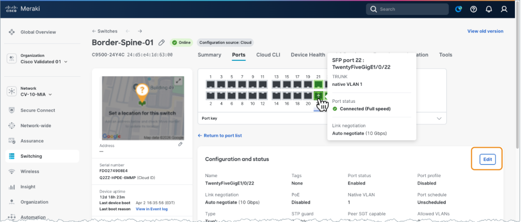
4. Select Routed Port.
Note: When the port is switched from Switch port to Routed port, the system automatically enables Layer 3 configuration and redirects to eth routing screen with relevant fields pre-populated, which reduces input errors and streamlines deployment.
5. Check the Navigate to configure routed port checkbox.
6. Name the port. For example: GigabitEthernet1/0/48
7. Set Port status to Enabled.
8. Leave the remaining settings as their default values.
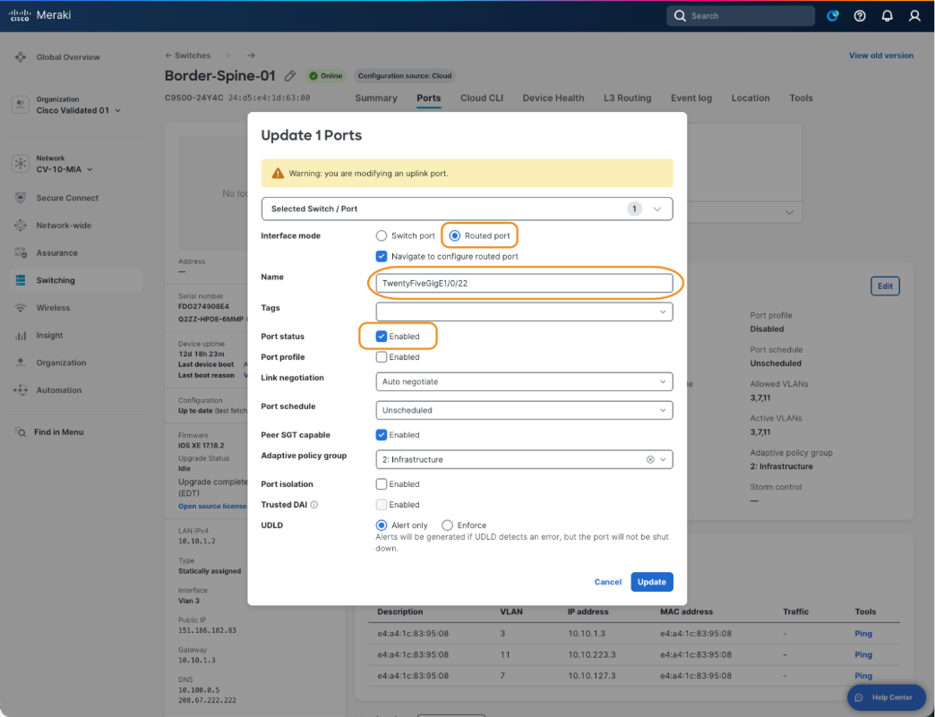
Because this is the first Layer 3 interface configured on this switch, the Preferred Uplink > IPv4 Preferred Management Connectivity setting is automatically selected and must remain enabled to save the configuration. If additional interfaces are later converted to Layer 3, the management uplink designation can be reassigned as necessary. A static default route is automatically created according to the configured next-hop gateway.
There are also configuration options for DHCP and OSPF. Because OSPF provides Layer 3 management routing in the underlay, it must be enabled and the interface assigned to the appropriate OSPF area defined during planning. A point-to-point network type is recommended to avoid unnecessary DR/BFR elections. DHCP is typically disabled on fabric links but may be temporarily enabled to support day-two RMA procedures or the additional of new leaf devices.
The resulting Layer 3 interface and static route definitions can be found by navigating to Switching > Routing and DHCP in the UI.
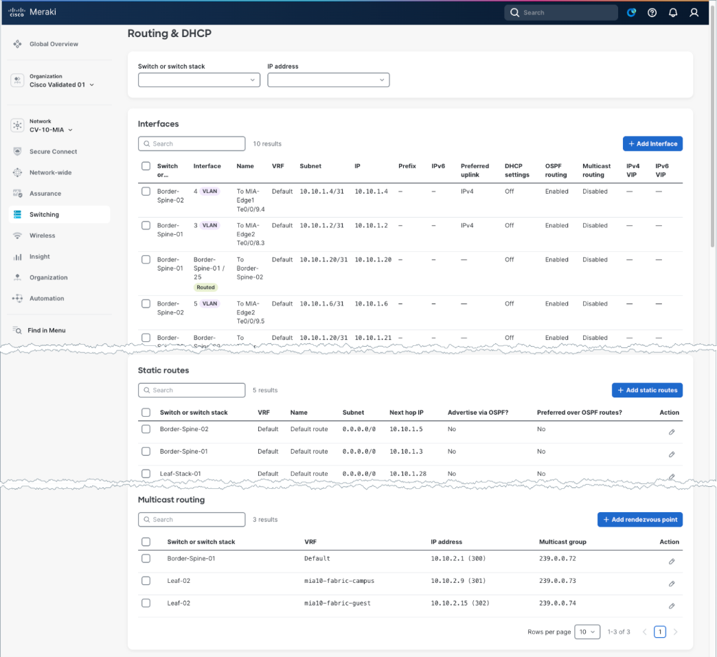
Note: The default behavior for the static route that is automatically created, is to have the available additional OSPF settings both set to No. This is important, aligned to best practice, and will result in a static route being added to the configuration with an administrative distance (AD) of 120 and not redistributed into OSPF. Since OSPF uses an AD of 110, the OSPF learned default route advertised from the handoff devices into the borders will be preferred in the active routing table. The static route is essentially a floating static backup route.
Upon completion of the Layer 3 underlay conversion, the underlay routing table (global routing table) will contain OSPF-learned or directly connected routes for all the fabric links, along with a default route toward the borders for external reachability. Access layer management subnets and any traditional non-fabric subnets will also reside in the underlay routing domain.
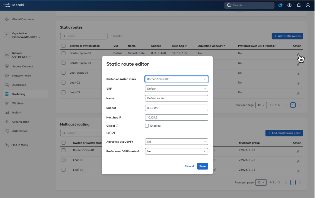
This can be reviewed by selecting the configuration icon of a switch in the Static routes table.
Note: When an interface is converted from a routed port back to a switched port, any associated Layer 3 configuration is automatically removed.
Welcome to the interactive CLI IOS XE terminal
You are in Read-only Mode
Establishing connection to your device. Please wait...
Connection established successfully
MIA10-Leaf-02>show run | inc ip route
ip route 0.0.0.0 0.0.0.0 10.10.1.34 120
MIA10-Leat-02>show ip route
Codes: L - local, C - connected, S - static, R - RIP, M - mobile, B - BGP
D - EIGRP, EX - EIGRP external, O - OSPF, IA - OSPF inter area
N1 - OSPF NSSA external type 1, N2 - OSPF NSSA external type 2
E1 - OSPF external type 1, E2 - OSPF external type 2, m - OMP
n - NAT, Ni - NAT inside, No - NAT outside, Nd - NAT DIA
i - IS-IS, su - IS-IS summary, L1 - IS-IS level-1, L2 - IS-IS level-z
ia - IS-IS inter area, * - candidate default, U - per-user static route
N - NHRP, G - NHRP registered, g - NHRP registration summary
o - ODR, P - periodic downloaded static route, 1 - LISP
a - application route
+ - replicated route, % - next hop override, p - overrides from Pfr
& - replicated local route overrides by connected
Gateway of last resort is 10.10.1.34 to network 0.0.0.0
0*E1 0.0.0.0/0 [110/3] via 10.10.1.30, 4d18h, HundredGigE1/0/52
[110/13] via 10.10.1.24, 4d18h, HundredGigE1/0/51
Step 6. Complete the underlay conversion.
Complete the conversion of all underlay links to Layer 3 and confirm.
1. On each fabric device, verify the correct number of OSPF neighbors, IP routing including redundant default routes, and minimal spanning trees. There should be no STPs on the spines.
2. At this stage, the DHCP scope for VLAN 1 on Handoff-01 can be removed but is often retained to support a day-two RMAs or factory resets. If a spine is replaced or reset, a temporary DHCP pool must be created on a border, and one border interface temporarily converted back to Layer 2 to support the onboarding of the returned spine. A similar process is required for a leaf with the DHCP and the temporary Layer 2 link living on the spine and is the most common scenario when adding new leaves. In all cases, the objective is to use a temporary VLAN 1 for initial cloud connectivity and then convert to Layer 3 connectivity.
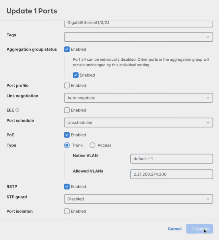
3. Once the routed underlay is stable, the leaf-to-access layer trunks can be enabled. These trunk links carry the UAC management VLAN for all downstream cloud-managed devices. VLAN 2 was used for this in the validation setup. Before activating the ports, clear the VLAN allowlist to include just the management of VLAN and any other traditional subnets if present. The access layer devices will run MST initially until they connect to the cloud and are configured to run RPVST+. These devices require DHCP, and these DHCP scopes will remain in place.
4. Add Layer 3 SVI for the access layer VLANs on each leaf and set the DHCP settings as required.
Remember these VLANS are unique broadcast domains and not connected between leaves allowing for the same VLAN numbers to be used if desired.
5. Unique IP subnets are required.
Remember to enable OSPF on the SVIs in the desired non-zero OSPF Area. Set them to OSPF Passive as there will be no downstream OSPF neighbors in the access layer.
It is best practice to enable automatic fallback to preferred uplink in the global switch settings and set the preferred uplink VLAN on the access switches. This ensures the UAC traffic remains in the underlay as intended.
6. Set up EtherChannels for increased throughput and redundancy.
7. Set up access ports and enable dot1x for desired access devices.
8. Enable CTS in-line tagging using the Peer SGT capable setting on both sides of the leaf ports facing the access layer devices and border ports facing the handoff devices. Any APs attached to access switch ports must also have Peer SGT enabled. Always select Adaptive policy group 2: Infrastructure when enabling the CMD header for infrastructure-to-infrastructure links.
Final underlay topology
When complete underlay connectivity is in place, all devices are registered in the UI and stable; the setup is ready for the fabric workflow to create the desired fabrics and related configurations.
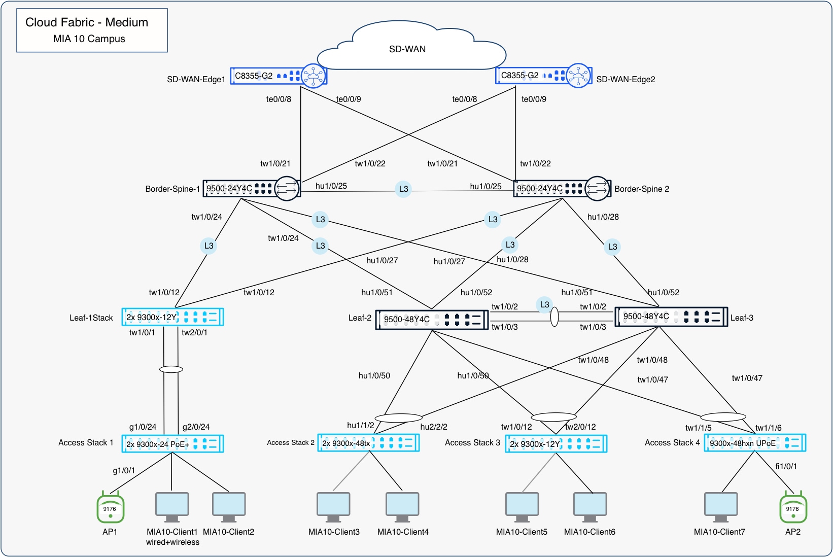
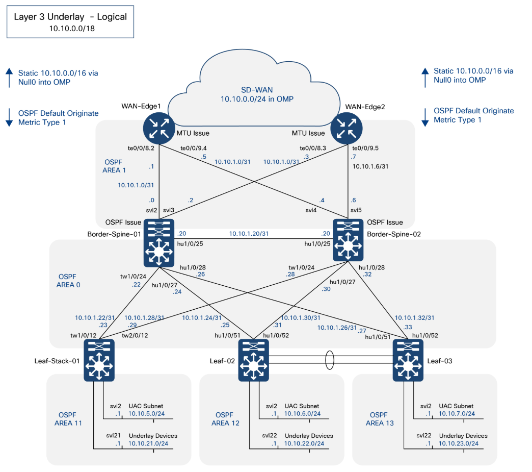
The underlay is now ready for overlay provisioning via the fabric workflow.
Deploy overlay fabric networks
Reference campus (MIA10) plan
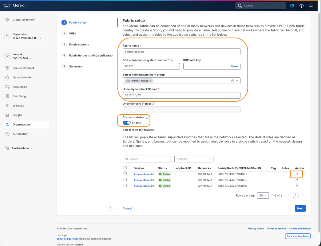
Once the underlay is prepared and stable, the fabric workflow is used to create and maintain the fully automated campus fabric. The first portion of the workflow collects the information required for the infrastructure including the name of the fabric, the fabric BGP AS, and the underlay type and subnet.
The best practice recommendation is to use a Layer 3 underlay, which is known as a Custom underlay in the UI. As the workflow progresses, VRF and eBGP handoff information are added along with one or more fabric subnets, which can be Routed, Routed DAG, and/or Bridged DAG subnets in any combination and leaf distribution.
Fabric settings
| Field |
Value |
| Fabric Name |
MIA10-fabric |
| Fabric BGP AS |
65208 |
| BGP Auth Key |
C1sco12345 |
| Selected Networks |
CV-10-MIA |
| Underlay Loopback IP Pool |
10.10.2.0/23 |
| Underlay core IP Pool |
N/A as setup is using L3 Underlay |
| Custom Underlay |
"Enabled" |
| VRF |
mia10-fabric-campus |
Device roles
| Device |
Fabric Role |
| MIA10-Border-Spine-01 |
Spine, Border |
| MIA10-Border-Spine-02 |
Spine, Border |
| MIA10-Leaf-01 |
Leaf |
| MIA10-Leaf-02 |
Leaf |
| MIA10-Leaf-03 |
Leaf |
Fabric subnets
| Subnet Name |
VLAN Name |
Type |
VLAN ID |
SVI IP and Mask |
DHCP Server(s) |
VRF |
Leaves |
Anycast Gateway |
Broadcast Replication |
| leaf1-routed |
leaf1-routed |
Routed (no DAG) |
200 |
10.10.64.1/24 |
10.100.0.5 |
mia10-fabric-campus |
leaf-01 |
unchecked |
unchecked |
| leaf2-routed |
leaf2-routed |
routed (no DAG) |
200 |
10.10.65.1/24 |
10.100.0.5 |
mia10-fabric-campus |
leaf-02 |
unchecked |
unchecked |
| leaf3-routed |
leaf3-routed |
routed (no DAG) |
200 |
10.10.66.1/24 |
10.100.0.5 |
mia10-fabric-campus |
leaf-03 |
unchecked |
unchecked |
|
|
|
|
|
|
|
|
|
|
|
| routed-dag1 |
routed-dag1 |
routed DAG |
274 |
10.10.74.1/24 |
10.100.0.5 |
mia10-fabric-campus |
leaf-01, leaf-02 |
checked |
unchecked |
| routed-dag2 |
routed-dag2 |
routed DAG |
275 |
10.10.75.1/24 |
10.100.0.5 |
mia10-fabric-campus |
leaf-02, leaf-03 |
checked |
unchecked |
|
|
|
|
|
|
|
|
|
|
|
| bridged-dag1 |
bridged-dag1 |
Bridged DAG |
284 |
10.10.84.1/24 |
10.100.0.5 |
mia10-fabric-campus |
leaf-02, leaf-03 |
checked |
checked |
BGP Layer 3 connection information
| Switch |
Name |
VRF |
VLAN |
MTU |
IP/Mask |
| Border-Spine-01 |
WAN-Edge-01 |
mia10-fabric-campus |
6 |
1500 |
10.10.127.0/31 |
| Border-Spine-01 |
WAN-Edge-02 |
mia10-fabric-campus |
7 |
9100 |
10.10.127.2/31 |
| Border-Spine-02 |
WAN-Edge-01 |
mia10-fabric-campus |
8 |
9100 |
10.10.127.4/31 |
| Border-Spine-02 |
WAN-Edge-02 |
mia10-fabric-campus |
9 |
9100 |
10.10.127.6/31 |
BGP peer information
| Neighbor IP |
Remote AS |
VRF |
Source Int |
MD5 String |
| Peers on Border-Spine-01 |
|
|
|
|
| 10.10.127.1 |
65207 |
mia10-fabric-campus |
10.10.127.0/31 |
C1sco12345 |
| 10.10.127.3 |
65207 |
mia10-fabric-campus |
10.10.127.2/31 |
C1sco12345 |
| Peers on Border-Spine-02 |
|
|
|
|
| 10.10.0.127.5 |
65207 |
mia10-fabric-campus |
10.10.127.4/31 |
C1sco12345 |
| 10.10.0.127.7 |
65207 |
mia10-fabric-campus |
10.10.127.6/31 |
C1sco12345 |
EVPN multi-homing workflow
The EVPN multi-homing provides an option to build seamless redundancy at the distribution layer providing multi-homing to the access layer switches. EVPN multi-homing pair is created from the EVPN multi-homing page, and this pair is used in the fabric workflow.
1. Navigate to Switching > Configure > EVPN Multi-Homing.
2. Select Create EVPN-MH pair.
3. Enter a descriptive name and select the two supported distribution layer switches that will form the pair.
4. Enter the BGP autonomous system number (ASN) used by the target fabric.
5. Select an existing loopback or create one for each member. Assign a unique /32 IP address to each loopback for direct BGP EVPN peering between the two leaves. Loopback100 is reserved for fabric use and cannot be selected.
6. Select at least two physical interfaces on each member for the EVPN-MH inter-ES port-channel. An eligible existing port-channel can also be selected.
7. Assign a /31 subnet to the routed inter-ES link. Dashboard configures the port-channel and enables OSPF on the link.
8. Review the configuration and save the EVPN-MH pair. The completed pair is then available for fabric onboarding.
This creates an EVPN-MH pair in the network that can be used as a fabric device in the fabric workflow as we start to build the fabric.
Fabric setup workflow
The fabric workflow in the Meraki Dashboard provides a structured, automated process for defining fabric infrastructure parameters, creating VRFs and subnets, configuring border handoffs and eBGP peering, and deploying the complete campus fabric configuration to the validated environment. The screen captures and related information below outlines the current reference deployment of campus fabric workflow.
From a Secure Network Reference Architecture (SNRA) perspective, this workflow primarily operationalizes the Secure Network Infrastructure and Scalable Network Segmentation layers by establishing the physical and logical fabric constructs that enable segmentation, routing, and transport across the campus.
In the validated environment, the fabric workflow was exercised as part of early-stage functional validation to confirm end-to-end client connectivity across the campus fabric prior to enabling advanced access controls such as 802.1X.
1. Navigate to Organization > Fabric.
2. Click Create a fabric.
3. Enter a Fabric name in lower case. This is not the VRF name, which will be addressed later.
4. Enter the BGP autonomous system (AS) number and auth key.
This AS will be used with automated BGP configurations for the Layer 2 VPN EVPN address family inside the fabric.
5. Use the dropdown to select network/network group.
6. Enter the Underlay loopback IP pool.
Note: Be sure to allocate sufficient address space initially as the pool cannot be expanded without redeploying the fabric. This pool is used for all underlay loopbacks, including VTEPs and spine functions such as Anycast RP and MSDP, and is consumed dynamically by automation.
7. Enable Custom Underlay.
Default underlay uses SVIs. Enabling custom underlay implements a recommended Layer 3 routed underlay (manual configuration required), which removes the dependency on the underlay core pool.
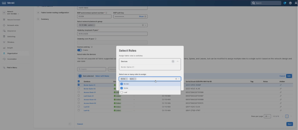
8. Click the edit icon for each device.
9. Mark the Border and Spine options for border/spine devices.
10. Mark the Leaf option for leaf devices.
11. Click Save on each assignment.
12. When finished, click Next.
The creation of VRFs directly aligns to the SNRA Scalable Network Segmentation layer, enabling logical isolation of traffic domains while leveraging a shared Secure Network Infrastructure.
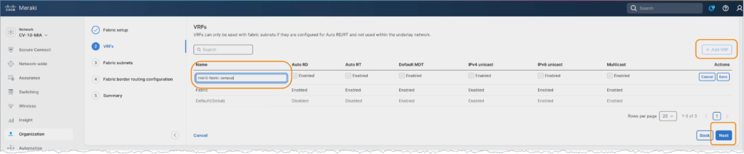
Note: There is one VRF called Fabric that will be created by default as part of the workflow; however, users can define a custom VRF (e.g., mia10-fabric-campus). Be sure to use a consistent naming convention, keeping in mind longer names increase CLI command length.
13. Click Add VRF.
14. Enter a name and click Next.
Note: Other VRFs created outside the fabric workflow will display, but they are not eligible for use in the workflow. Ensure the DHCP server supports VRF-aware options, as requests are sourced from the underlay loopback. DHCP scopes must be configured using the selected VRF.
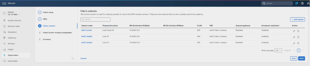
One or more fabric subnets are added, and the leaves where the subnet should be deployed are selected.
Fabric subnets and their association to specific leaf nodes represent the distributed instantiation of segmentation policy within the Scalable Network Segmentation layer.
15. Click Add subnet.
16. Enter a Subnet name.
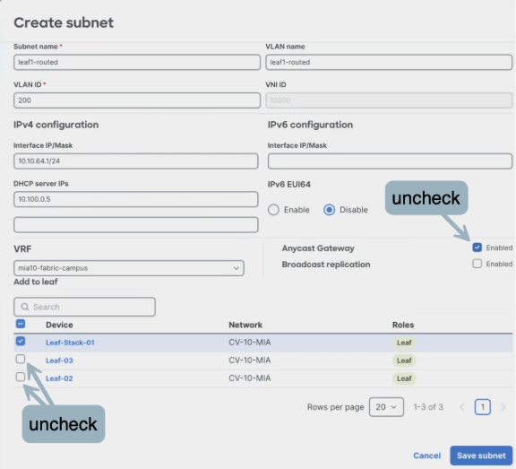
Note: Subnets can be added or modified at any time. Create the initial subnet (e.g., leaf1-routed), assign the VLAN (e.g., ID 200), and allow the system to auto-assign the L2 VN ID.
17. Enter a VLAN ID.
18. Enter an Interfaced IP/Mask.
19. Enter a DHCP server IP.
20. Select a VRF.
21. Uncheck the Anycast Gateway option to disable the routed DAG and deploy unique routed subnets per leaf, even if using the same VLAN ID. This aligns with best practice to route everywhere and avoid stretching subnets unless required.
22. Select only the target leaf for deployment and deselect the others as this is a unique routed subnet.
Anycast Gateway and forwarding mode selections define how traffic is handled within the Secure Network Infrastructure, while also influencing segmentation behavior within the Scalable Network Segmentation layer.
23. Select Save subnet.
24. Repeat the same steps for each of the subnets.
25. Click Next when finished.
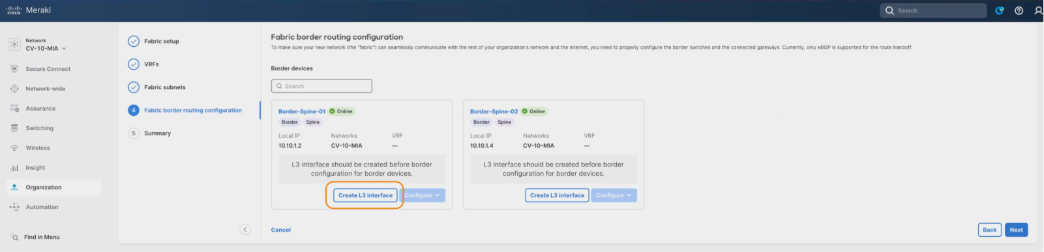
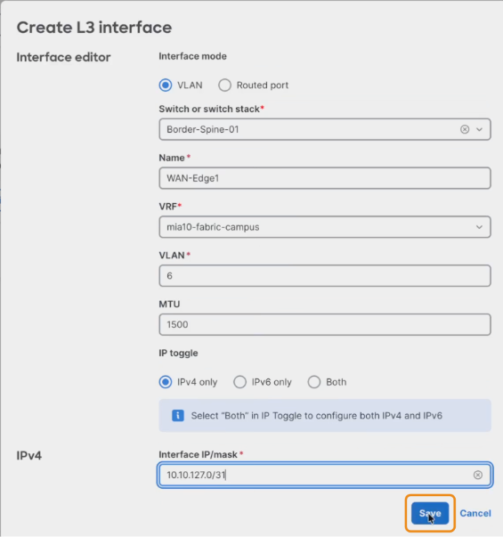
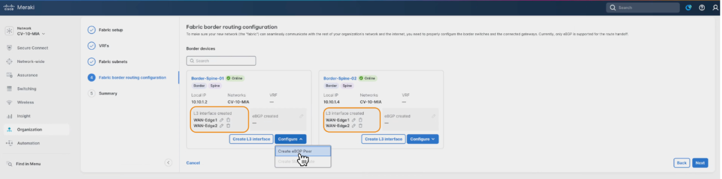
26. Select the Create L3 Interface option to add the settings for each Layer 3 handoff link. The validation setup process is repeated for each handoff link in the fabric VRF. Layer 3 handoff configuration extends the Secure Network Infrastructure beyond the fabric boundary and provides integration points into the Extended Integration layer for northbound connectivity.
27. Select a Switch from the dropdown.
28. Enter the Name, VLAN, MTU, and Interface IP/mask.
Note: For this validation, the MTU was set at 1500, however, best practice MTU recommendations for Cisco Meraki is to use 9100, which was set at the network level earlier in this workflow and is therefore the default setting here.
29. Click Save and repeat for each device.
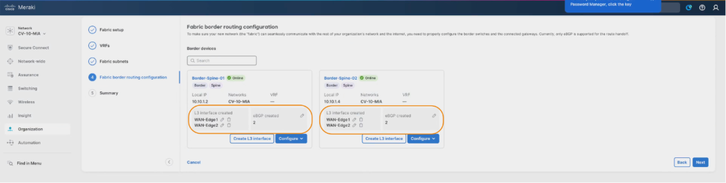
The validation setup process is repeated for each handoff link in the fabric VRF. Layer 3 handoff configuration extends the Secure Network Infrastructure beyond the fabric boundary and provides integration points into the Extended Integration layer for northbound connectivity.
During validation testing, Layer 3 handoff resiliency was also verified by disabling one of the uplinks from a leaf to a spine node. This ensured that traffic continued to forward correctly over the remaining active path, validating proper failover behavior within the fabric.
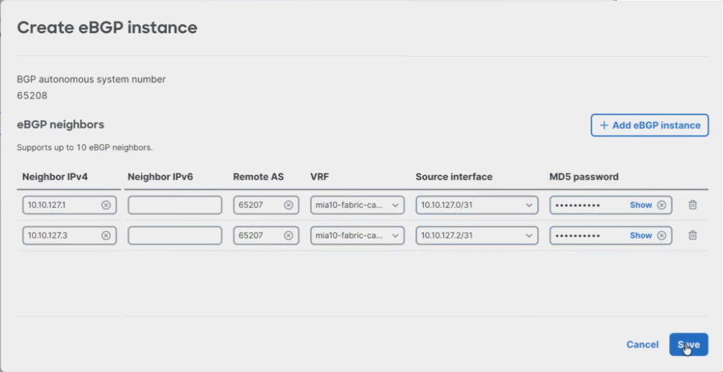
30. After adding the Layer 3 link information, click Configure > Create eBGP Peer to add the corresponding eBGP peering information for each link. eBGP peering establishes dynamic routing exchange between the fabric and external domains, reinforcing both the Secure Network Infrastructure and Extended Integration layers.
This is done uniquely on each border resulting in two peers on each border in the validated setup.
31. Click Add eGBP instance to allow adding both peers at once.
32. Select the VRF and Source interface in both entries, adding the fabric first to ensure correct interface selection and reduce input errors.
33. Enter the Neighbor IPv4, Remote AS, MD5 password for each instance.

34. Click Save.
35. Repeat the same steps for the additional border/spine.
eBGP peering stability and convergence were implicitly validated during live traffic testing by maintaining continuous client-to-client communication flows while topology changes (such as uplink shutdown) were introduced.
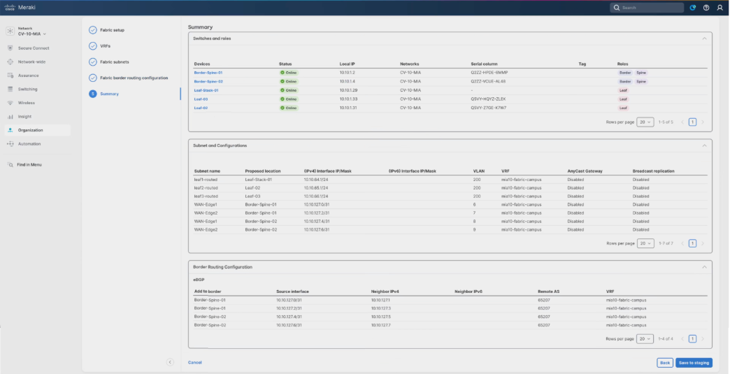
36. Click Next. Review the Summary screen. This page displays the completed border configuration, which can be updated at any time if the border configurations require modification.
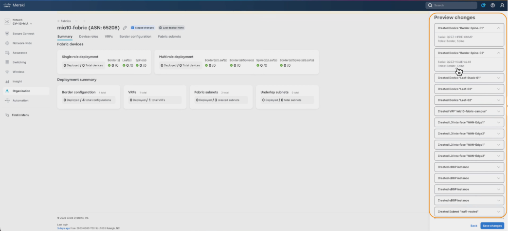
37. Click Save to staging once the values are set as intended.
Notice that the Status is Staged at this point.
38. Click the Fabric name for the option to deploy.
39. Click Preview changes to review high-level configuration logic and deployment targets. This option does not display CLI commands. Use CLI programmability if command-level visibility is required.
The staging, preview, and deployment workflow is part of the Unified Management and Agentic Operations layer, providing centralized orchestration, validation, and lifecycle control of the fabric.
40. Click through the page tabs to review the configuration and make any necessary changes.
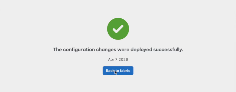
41. Click Deploy and Proceed to start the deployment. Allow time for deployment and removal operations and validate device configurations post-deployment to ensure consistency.
Note: Ensure all changes are saved before deployment, allow time for configurations to propagate to devices, and verify successful updates at the switch level. After deployment, additional subnets and VRFs can be added or modified. Thorough pre-deployment planning of underlay and overlay addressing is critical.
42. Click Back to fabric.
Within a few minutes the configurations will be delivered to the devices from the cloud, and the fabric subnets and related capabilities are ready for use.
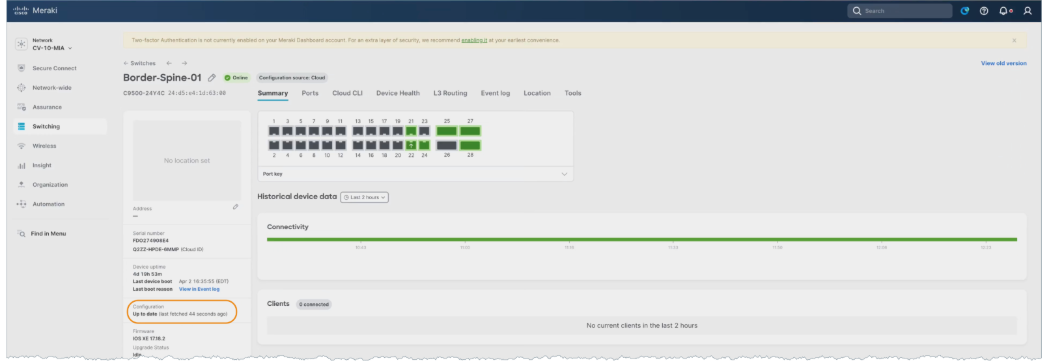
43. To prove the deployment was successful, navigate to Switching > Switches and see that the Configuration displays Up to date.

This cloud-driven deployment model exemplifies the Unified Management and Agentic Operations layer by abstracting configuration complexity and enabling consistent, automated provisioning across the fabric.
Following deployment, validation testing included continuous ICMP traffic between endpoints connected to different access switches to confirm that inter-leaf routing and fabric forwarding were operating as expected.
Packet-level verification was performed using the Meraki Dashboard packet capture tool at the leaf and border layers to confirm correct forwarding behavior and validate that traffic paths aligned with the intended fabric design.
The entire fabric can be deleted with a fully automated cleanup using the Delete option.
Automated teardown further demonstrates lifecycle management capabilities within the Unified Management and Agentic Operations layer.
Fabric validation and policy enablement workflow
Following deployment of the fabric, a structured validation and policy enablement process was performed to confirm correct forwarding behavior, resiliency, segmentation, and identity-based access control.
From an SNRA perspective, this phase extends validation of the Secure Network Infrastructure and Scalable Network Segmentation layers, while introducing capabilities aligned to the Zero Trust Access and Hybrid Mesh Firewall layer.
Step 1. Perform baseline client connectivity validation prior to advanced policy enablement.
After initial fabric deployment, verify end-to-end connectivity between clients across different leaves and subnets using continuous ICMP testing.
This step ensures that the Secure Network Infrastructure and Scalable Network Segmentation layers are functioning correctly before introducing additional policy controls.
Use the Meraki Dashboard packet capture capability at leaf and border nodes to inspect live traffic flows and confirm proper forwarding behavior across the fabric.
This validation step ensures that encapsulation, routing, and segmentation policies are operating as designed within the Secure Network Infrastructure layer.
Step 2. Perform fabric resiliency testing through link failure simulation.
Administratively disable one or more uplinks (for example, a leaf-to-spine connection) to validate convergence and failover behavior.
Confirm that traffic continues to flow over alternate paths without disruption to active client sessions.
Step 3. Validate segmentation behavior across VLANs, VRFs, and SGT-based policy.
Test connectivity between endpoints in the same and different VLANs and VRFs to confirm expected communication and isolation behavior.
Step 4. Introduce 802.1X-based access control after baseline validation.
After confirming stable fabric connectivity, enable 802.1X authentication on the SSID or wired access ports to transition from open or PSK-based access control.
This staged approach ensures that any connectivity issues can be isolated between infrastructure and policy layers.
Step 5. Configure dynamic VLAN and SGT assignments via identity policy.
Integrate Access Manager with Cisco ISE to dynamically assign VLANs and Security Group Tags based on user or device identity during 802.1X authentication.
This step operationalizes the Zero Trust Access and Hybrid Mesh Firewall layer by extending identity-based segmentation into the fabric.
Test environments where both statically assigned ports (manual VLAN/SGT) and dynamically assigned ports (802.1X) coexist.
Confirm consistent policy enforcement and interoperability across both access models.
Step 6. Validate identity-based access and policy enforcement.
After enabling 802.1X, perform connectivity tests to confirm that:
1. Authenticated users receive the correct VLAN and SGT
2. Policy enforcement behaves as expected (allowed/denied communication)
3. Fallback or default access behavior operates correctly
This ensures proper alignment between the Scalable Network Segmentation and Zero Trust Access and Hybrid Mesh Firewall layers.
Step 7. Iterate validation during incremental configuration changes.
As additional features (VRFs, policies, authentication methods) are introduced, repeat validation testing to ensure no regression in connectivity, segmentation, or policy enforcement.
This iterative validation approach reflects the stepwise testing methodology observed across all transcripts.
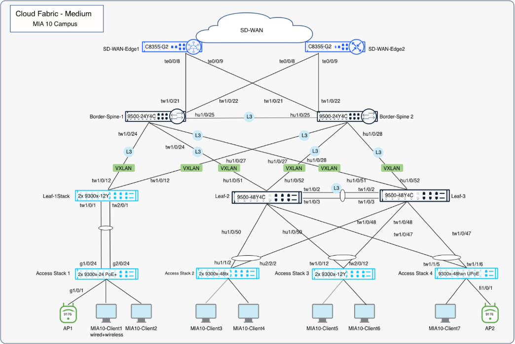
Final topology
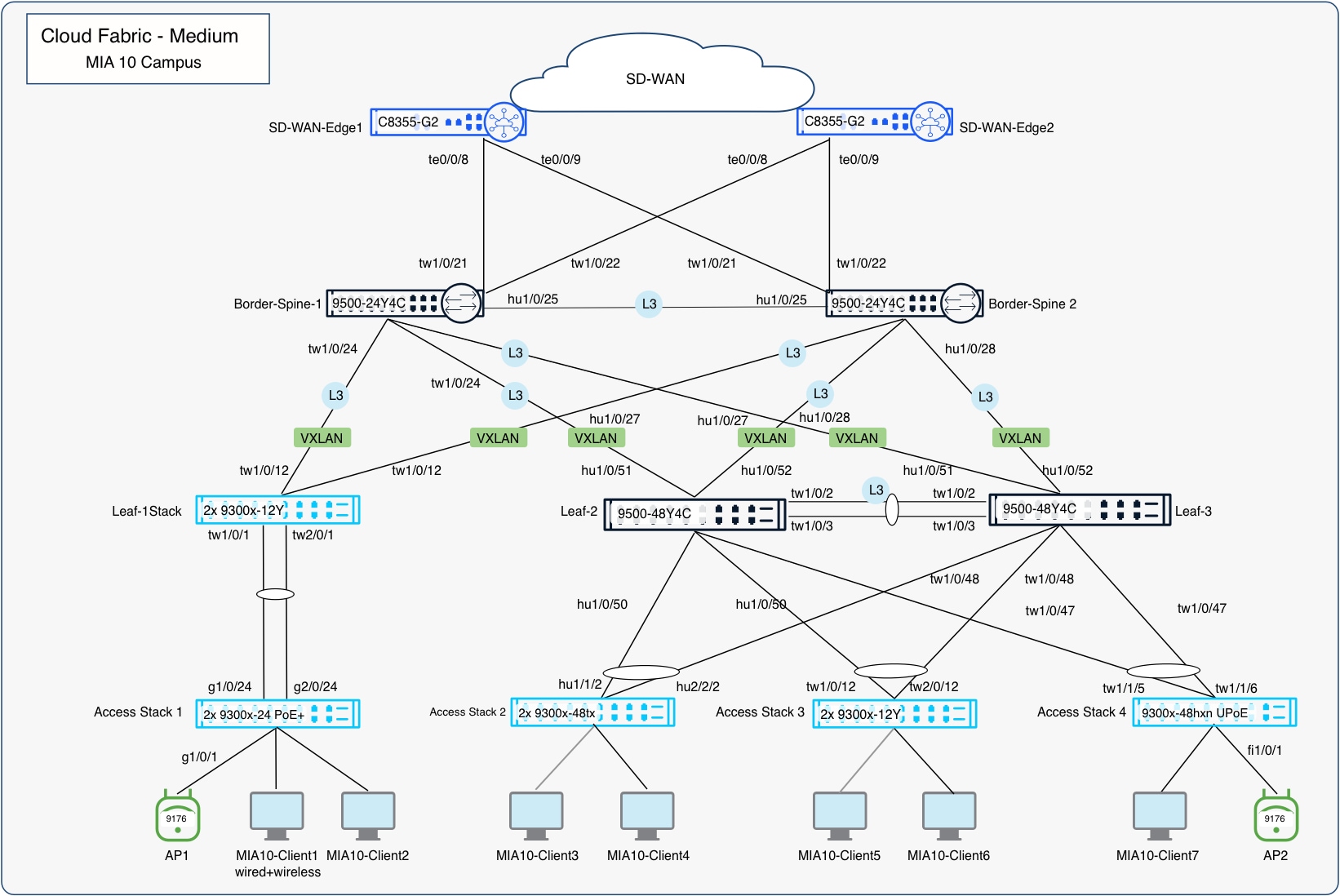
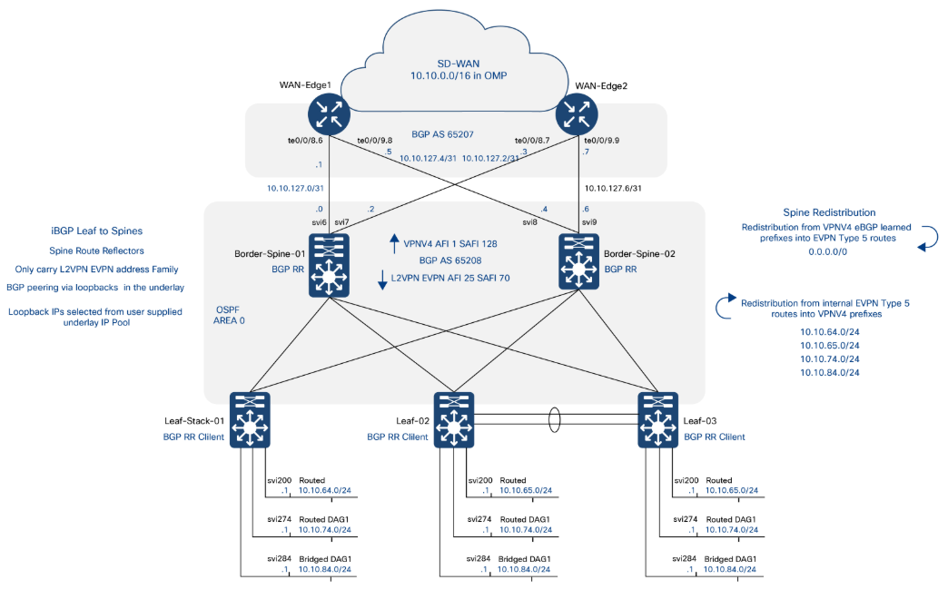
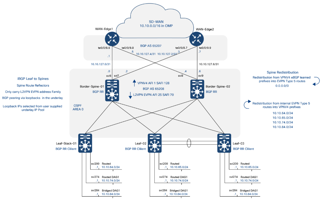
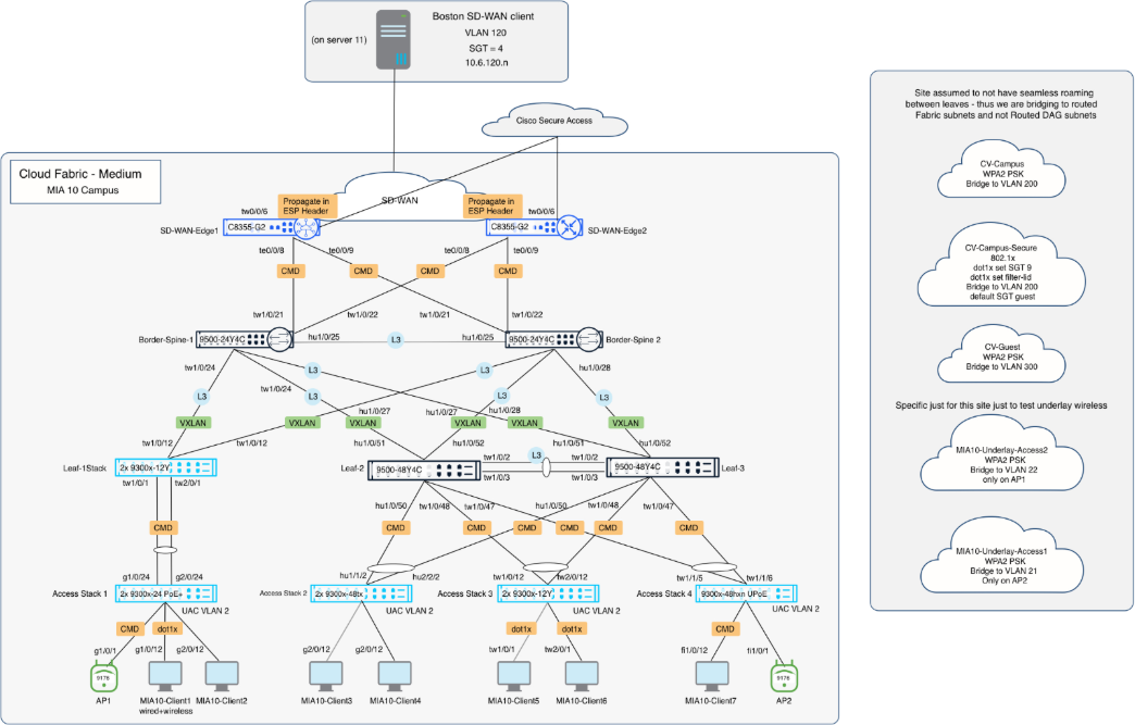
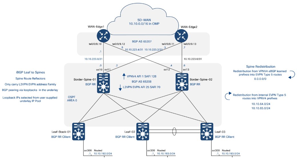
The Layer 3 topology highlights routing domains, VRFs, and segmentation boundaries aligned with the Scalable Network Segmentation layer.
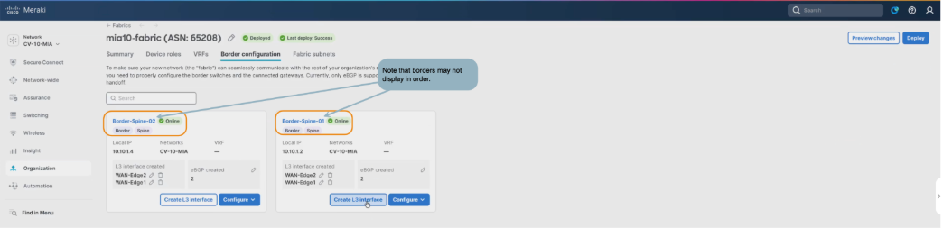
Multiple VRFs
It is possible to create multiple VRFs in a fabric. An additional VRF was created on all leaf switches in the validated setup to isolate guest traffic on wired guest ports. Multiple VRFs are a foundational capability of the Scalable Network Segmentation layer, enabling secure multi-tenancy and traffic isolation within a shared infrastructure.
In the validated environment, VRFs are instantiated consistently across all participating leaf nodes as part of the fabric workflow, ensuring uniform segmentation and policy application across the fabric.
The use of multiple VRFs was also validated operationally by confirming traffic isolation between fabric VRFs while maintaining expected connectivity within each VRF domain.
Validation included verification of control-plane and data-plane separation using EVPN (L2VPN EVPN AFI/SAFI) to ensure that endpoint reachability information is exchanged only within the appropriate VRF context, reinforcing strict segmentation boundaries.
Guest VRF workflow
Fabric settings – additional guest VRF
| Field |
Value |
| Fabric Name |
mia10-fabric |
| VRF Name |
mia10-fabric-guest |
Fabric subnets
| Subnet Name |
VLAN Name |
Type |
VLAN ID |
SVI IP and Mask |
DHCP Server(s) |
VRF |
Leaves |
Anycast Gateway |
Broadcast Replication |
| MH-guest-routed |
MH-guest-routed |
routed (no DAG) |
300 |
10.10.192.1/24 |
10.100.0.5 |
mia10-fabric-guest |
leaf-01 |
unchecked |
unchecked |
| leaf2-guest |
leaf2-guest |
routed (no DAG) |
300 |
10.10.193.1/24 |
10.100.0.5 |
mia10-fabric-guest |
EVPN-MH pair [ leaf-02, leaf-03] |
unchecked |
unchecked |
BGP Layer 3 connection
WAN-Edge side has higher host IP addresses.
| Switch |
Name |
VRF |
VLAN |
MTU |
IP/Mask |
| Border-Spine-01 |
WAN-Edge-01 |
mia10-fabric-guest |
10 |
9100 |
10.10.223.0/31 |
| Border-Spine-01 |
WAN-Edge-02 |
mia10-fabric-guest |
11 |
9100 |
10.10.223.2/31 |
| Border-Spine-02 |
WAN-Edge-01 |
mia10-fabric-guest |
12 |
9100 |
10.10.223.4/31 |
| Border-Spine-02 |
WAN-Edge-02 |
mia10-fabric-guest |
13 |
9100 |
10.10.223.6/31 |
BGP peer information
| Neighbor IP |
Remote AS |
VRF |
Source Int |
MD5 String |
| Peers on Border-Spine-01 |
|
|
|
|
| 10.10.223.1 |
65207 |
mia10-fabric-guest |
10.10.223.0/31 |
C1sco12345 |
| 10.10.223.3 |
65207 |
mia10-fabric-guest |
10.10.223.2/31 |
C1sco12345 |
| Peers on Border-Spine-02 |
|
|
|
|
| 10.10.0.223.5 |
65207 |
mia10-fabric-guest |
10.10.223.4/31 |
C1sco12345 |
| 10.10.0.223.7 |
65207 |
mia10-fabric-guest |
10.10.223.6/31 |
C1sco12345 |
Guest fabric setup workflow
The guest VRF is created through the Fabric Workflow in the Meraki Dashboard, ensuring that it is eligible for fabric orchestration and automation. VRFs defined outside of this workflow may be visible but are not usable within the automated deployment process.
1. Navigate to Organization > Fabric.
2. Select the existing fabric.
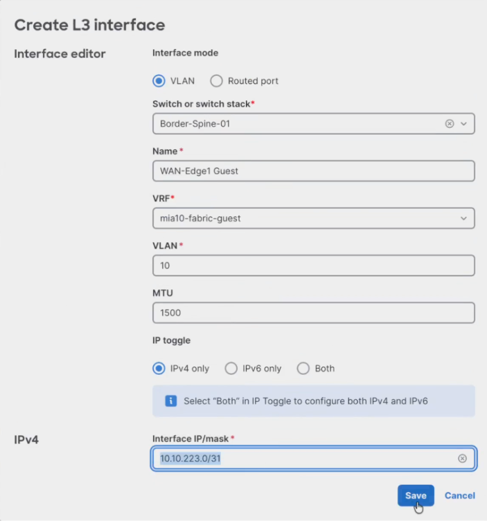
3. Click Add VRF to add new routed fabric subnets.
Guest subnets are configured as routed (no DAG) to align with best practices that favor Layer 3 segmentation and avoid extending Layer 2 domains unless mobility requirements dictate otherwise.
4. Enter the Guest VRF Name in all lower case.
5. Click Save.
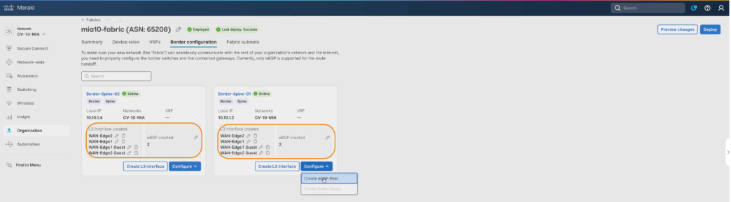
6. Select the Border configuration tab.
7. Select the Create L3 Interface option for Border-Spine-01 to add the settings for each Layer 3 handoff link.
8. Add one or more subnets and associate them with the guest VRF from the planning sheet.
Subnet-to-leaf mapping enforces localized gateway behavior, ensuring that traffic is routed at the ingress leaf and does not rely on stretched Layer 2 adjacency across the fabric.
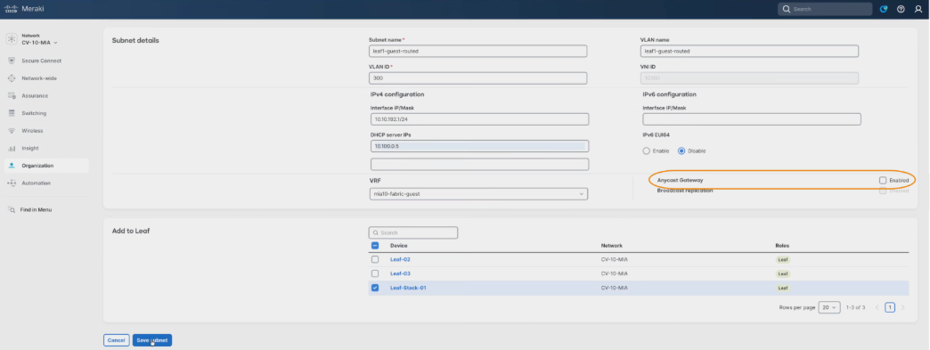
9. Configure the subnet parameters.
10. Click Save.
11. Repeat these steps for the other interfaces.
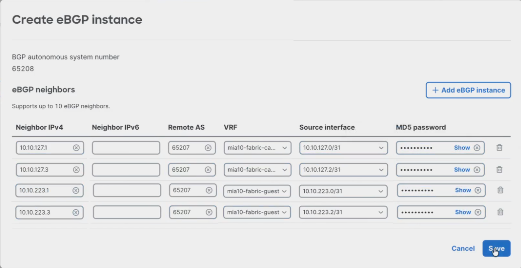
12. Click Add eGBP instance to allow adding both peers at once.
13. Select the VRF and Source interface in both entries, adding the fabric first to ensure correct interface selection and reduce input errors.
14. Enter the Neighbor IPv4, Remote AS, MD5 password for each instance.
15. Click Save.
16. Repeat all steps for spine 2.
17. Select the Fabric subnets tab.
18. Enter the subnet details.
VLAN 300 is consistently used for guest access across all leaf switches; however, each leaf uses a unique subnet to maintain deterministic routing and minimize broadcast domains.
19. Select deployment targets (leaf switches).
The Guest VRF is explicitly instantiated on all participating leaf switches, confirming that segmentation is enforced consistently across the fabric edge.
Guest subnets are also configured as routed (no Distributed Anycast Gateway), reinforcing isolation and simplifying forwarding behavior for guest traffic.
20. Click Save subnet.
21. Repeat these steps for the additional subnets.
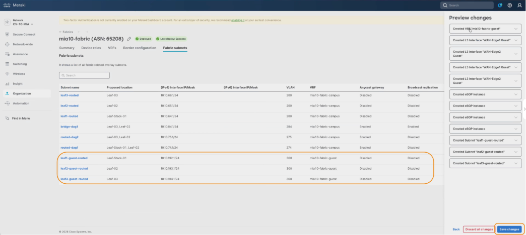
22. Select Preview changes to allow for saving the subnet configurations.
23. Click Save changes.
Note: Users must save changes through the Preview changes window. Any unsaved changes are lost during deployment.
24. Click Deploy and Proceed to start the deployment. Allow time for deployment and removal operations and validate device configurations for post-deployment to ensure consistency.
Post deployment validation
Post-deployment validation confirmed that guest VRF traffic remained isolated from the primary fabric VRF while still successfully reaching external network resources through the configured border handoffs.
Wired guests can come into play in various deployment scenarios. The validation setup uses both statically set guest ports with the guest VLAN and SGT hard coded, and dynamic 802.1x authentication with the VLAN and SGT set from the ISE policy.
Initial validation testing was performed without 802.1X enabled to establish a known-good baseline for connectivity before introducing identity-based access control policies.
Static guest port set to guest VLAN 300 with guest SGT (6) set.
To perform validation:
1. From Cloud CLI on a leaf switch, verify VRF creation by running:
show vrf
2. Confirm the guest VRF is present and associated with VLAN 300 SVI.
3. Verify SVI configuration for VLAN 300 by running:
show run interface vlan 300
Confirm:
◦ DHCP helper address is configured
◦ SVI is correctly bound to the guest VRF
4. Validate DHCP relay behavior. DHCP relay is sourced from the underlay loopback (Loopback100).
Ensure:
◦ DHCP server is reachable via the underlay network
◦ DHCP server is VRF-aware
If the DHCP server is not VRF-aware, return traffic will not map correctly back to the originating VRF, which will result in a failed address assignment.
5. From a border (spine) node, verify VRF presence by running:
show vrf
Confirm the guest VRF exists on the border function, where VPNv4 handoff occurs.
6. Verify BGP VPNv4 state by running:
show ip bgp vpnv4 vrf <guest-vrf> summary
Expect:
◦ BGP peers configured (e.g., dual WAN edge peers per spine for HA)
◦ Peers may not be fully established until WAN edge configuration is complete
7. Verify SVI status by running:
show ip interface brief
VLAN 300 SVI may appear up/down initially due to no active access ports or VLANs not yet carried on trunks.
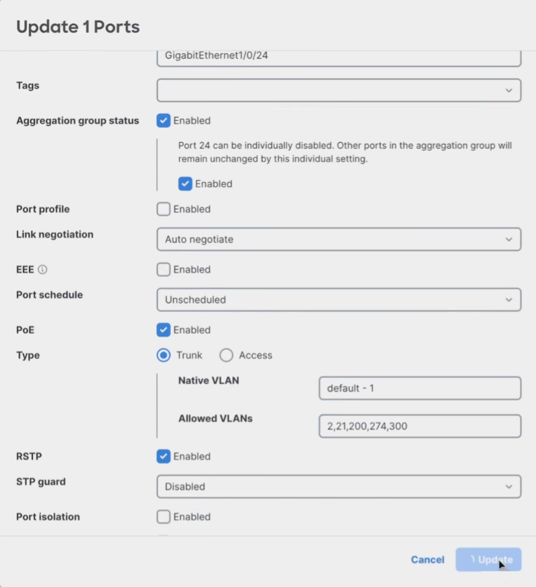
Final guest VRF topology
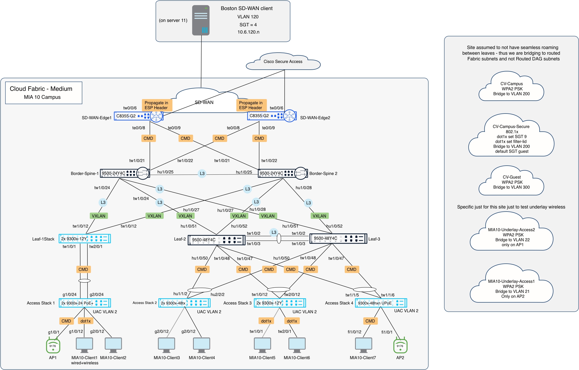
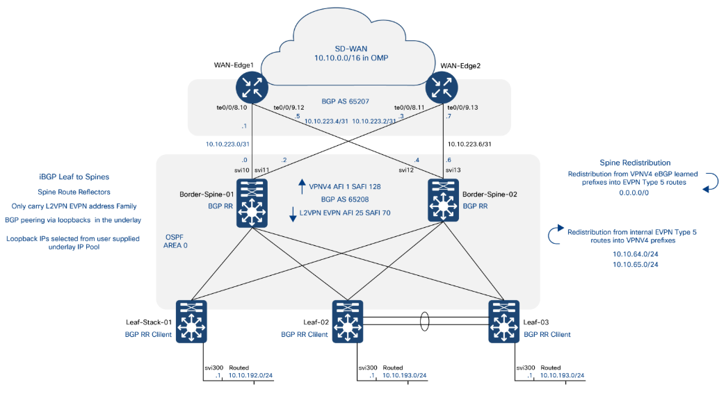
Conclusion
Through this Cisco Cloud Fabric validate case study, Cisco provides a future-ready foundation for mission-critical networks, combining deterministic performance, post-quantum security, Zero Trust enforcement, and intelligent automation in a unified architecture. By decoupling physical transport from policy-driven overlays, enforcing air-gapped trust boundaries, and standardizing validated configurations, organizations can reduce risk, simplify operations, and scale securely across diverse environments. Powered by Cisco Secure Routers and enhanced by integrated observability and orchestration, this architecture ensures continuous availability, rapid adaptability, and long-term resilience for the most demanding missions.