Cisco Catalyst SD-WAN Cloud OnRamp Connecting ACI to AWS Design Guide
Available Languages
Bias-Free Language
The documentation set for this product strives to use bias-free language. For the purposes of this documentation set, bias-free is defined as language that does not imply discrimination based on age, disability, gender, racial identity, ethnic identity, sexual orientation, socioeconomic status, and intersectionality. Exceptions may be present in the documentation due to language that is hardcoded in the user interfaces of the product software, language used based on RFP documentation, or language that is used by a referenced third-party product. Learn more about how Cisco is using Inclusive Language.
- US/Canada 800-553-2447
- Worldwide Support Phone Numbers
- All Tools
 Feedback
 Feedback
This design guide is intended to provide technical guidance around the design and deployment of Catalyst SD-WAN Cloud OnRamp connecting an on-premises Cisco Application Centric Infrastructure (ACI) fabric to Amazon Web Services (AWS).
Prerequisites
This document assumes that the reader has a basic knowledge of Cisco ACI technology. For more information, see the Cisco ACI white papers available at Cisco.com: https://www.cisco.com/c/en/us/solutions/data-center-virtualization/application-centric-infrastructure/white-paper-listing.html.
This document provides you with basic knowledge of ACI contracts. For detailed information, refer to the Cisco ACI Contract Guide: https://www.cisco.com/c/en/us/solutions/collateral/data-center-virtualization/application-centric-infrastructure/white-paper-c11-743951.html
This document provides you with basic knowledge of ACI L3Outs. For detailed information, refer to the Cisco ACI L3Out white paper: https://www.cisco.com/c/en/us/solutions/collateral/data-center-virtualization/application-centric-infrastructure/guide-c07-743150.html
This document provides you with basic understanding of the Cisco Catalyst SD-WAN design best practices: https://www.cisco.com/c/en/us/td/docs/solutions/CVD/SDWAN/cisco-sdwan-design-guide.html
This document provides the you with basic knowledge of the Cisco Catalyst Cloud OnRamp for Multicloud features: https://www.cisco.com/c/en/us/solutions/collateral/enterprise-networks/sd-wan/white-paper-c11-742817.html
This document provides you with basic knowledge of the Catalyst SD-WAN integration with AWS Cloud WAN solution: https://www.cisco.com/c/en/us/solutions/collateral/enterprise-networks/sd-wan/nb-06-catalyst-sd-wan-aws-cloud-wan-aag-cte-en.html
Terminology
This document uses the following terms, with which you will need to be familiar:
● TN: tenant
● VRF: virtual routing and forwarding
● BD: bridge domain
● EPG: endpoint group – a collection of endpoints attached to one or more VLANs within a VRF
● ESG: endpoint security group – a collection of endpoints within a VRF
● EP: endpoint residing in an ACI fabric
● L3Out: Layer 3 Out or external routed network
● External EPG: subnet-based EPG in L3Out
● Border leaf: ACI leaf where a L3Out is deployed
● “Application Centric” design and “Network Centric” design:
◦ In a typical “Network Centric” design a single EPG (security group) is created per Bridge Domain. The EPG typically contains a single VLAN ID, which is similar to a traditional network design. The network building blocks would be named in a manner which reflects the network constructs, e.g., “epg-vlan-10, epg-vlan-11, epg-vlan-12”.
● In an “Application Centric” design, one or more EPGs/ESGs are created on the same Bridge Domain. The network building blocks would be named in a way which reflects the application’s functionality, e.g., “epg-web, epg-app, epg-db.”
● VPN - network segmentation using Virtual Private Network.
● CoR – Cloud OnRamp, automation of cloud functionalities in Catalyst SD-WAN.
● OMP - Overlay Management Protocol is the protocol responsible for establishing and maintaining the Cisco SD-WAN control plane.
● WAN Edge – SD-WAN Edge platform, including Catalyst 8500 and Catalyst 8000V in this document.
● VPC –Virtual Private Cloud, on-demand configurable pool of shared network resources allocated within a public cloud environment.
● Transit VPC – a VPC, often with virtual routers in it, responsible for connecting multiple, geographically disperse VPCs and remote networks in order to create a global network.
● Host VPC – VPC that hosts workload.
● TGW – Transit Gateway
● CNE – Core Network Edge, the regional connection point managed by AWS in each Region, as defined in the core network policy.
● CGW – Cloud Gateway, consists of a pair of cloud services routers that are instantiated within a transit VPC
● C8000V – Catalyst 8000V routers.
● Intent management - Mapping workflow in SD-WAN Manager enables connectivity between Catalyst SD-WAN VPNs (segment) and VPCs
● Tag – label used in cloud environment to identify resources.
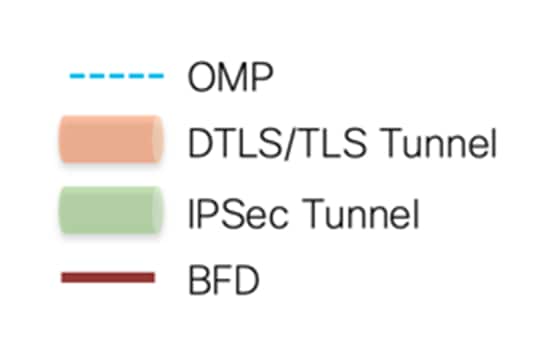
Figure 1 shows the icons used throughout this document.
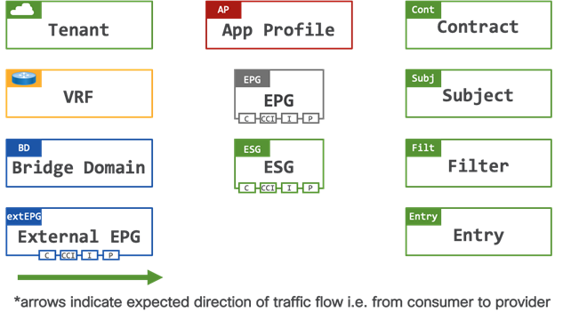
The object handles depict the following functions:
● C: Contract Consumer – a contract consumer is a group of endpoints which are consuming a service
● P: Contract Provider – a contract provider is a group of endpoints which are providing a service to the contract consumers
● CCI: Consumed Contract Interface – a consumed contract interface is a group of endpoints which are consuming a service, the contract interface is used when a contract is shared (exported) between different tenants
● I: Intra EPG/ESG Contract – an intra contract controls communication within a group of endpoints
Challenges in Hybrid Cloud Environments
As the adoption of hybrid cloud strategies grows, the industry is faced with increased complexity and different operating models. The main challenges in building and operating a hybrid cloud environment are:
● Creating secure connectivity between on-premises datacenters, branches, and public clouds.
● Dealing with different operating models and disjoint capabilities across on-premises private and public clouds.
● Network functions and scale limitations within the public cloud domains.
High-Level Architecture of Catalyst SD-WAN Cloud OnRamp Connecting ACI to AWS
This design guide aims to aid network or cloud-architects with design, configuration best-practices and considerations when designing and operating hybrid cloud environments. It describes the design of extending the SD-WAN architecture to connect workloads running in in datacenters powered by Cisco ACI, to applications in the public cloud (AWS) through SD-WAN Cloud OnRamp.
Cisco Catalyst SD-WAN connects users and workloads with integrated capabilities for Multicloud, security, predictive operations, and enhanced network visibility – all on a Secure Access Service Edge (SASE) – enabled architecture.
Leveraging these solutions together allows customers to significantly accelerate their hybrid cloud journey, by providing automated and secure connectivity between branches, datacenters, and clouds. It allows administrators to deliver network connectivity requirements faster, by reducing the manual labor required to operate hybrid networks.
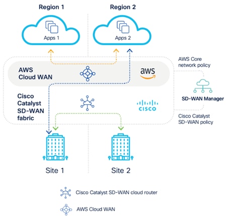
The key building blocks of the design described in this guide are shown in Figure 2. It includes the following:
1. Cisco Application Centric Infrastructure Fabric (ACI). This depicts a datacenter powered by ACI, hosting several tenants and VRFs – labelled in [1]. This building block is responsible for advertising tenant network prefix information of the respective VRF to the WAN Edge (Catalyst 8500) in the SD-WAN fabric.
2. Cisco Catalyst Software-Defined Wide Area Network Fabric (SD-WAN, Cisco / Catalyst SD-WAN), including Cloud Gateway (Catalyst 8000V) and WAN Edge (Catalyst 8500) – labelled in [2]. This building block is responsible for providing routed connectivity between datacenter and cloud while mapping the on-prem VRFs to SD-WAN VPNs and to the host VPC.
3. Amazon Cloud Infrastructure as a Service (IaaS), including Transit VPC, Transit Gateway/Cloud WAN , host VPC. This depicts a single geographic location, or region, which contains three distinct host VPCs, each containing multiple subnets – labelled in [3].
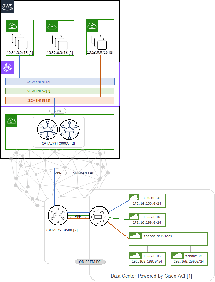
The ACI tenant VRFs are mapped into SD-WAN VPNs on the Catalyst 8500 which is acting as the WAN Edge between the ACI Fabric and the SD-WAN Fabric, it connects to ACI border leaf nodes using Inter-AS option A (back-to-back VRF) on the service VPN side and connects to the SD-WAN Fabric.
The SD-WAN Cloud OnRamp automation workflow will:
● Discover and tag the virtual private cloud (VPC) in the public cloud
● Create the cloud infrastructure (i.e., AWS TGW/CNE, Transit VPC) which connects all the VPCs
● Create the SD-WAN Cloud Gateways which consist of a pair of Catalyst 8000V in the Transit VPC
● Connect SD-WAN fabric the WAN Edge to the Cloud Gateway
● Connect Cloud Gateway to the TGW/CNE
● Map the connectivity between SD-WAN VPNs and VPCs, and VPCs to VPCs
The function and configuration of each SD-WAN building block are explained in detail in the Catalyst SD-WAN Building Blocks section.
Similar designs are possible with Azure using Virtual WAN (vWAN) and Google Cloud (GCP) using Network Connectivity Center (NCC). This design guide will primarily focus on connecting ACI to AWS, whilst briefly discussing the design consideration using Azure and Google Cloud.
ACI Building Blocks
This section is optional if you are already familiar with ACI. It aims to provide you with a fundamental understanding of the ACI building blocks involved in this design guide.
Understanding ACI Tenants
A tenant in an Application Centric Infrastructure (ACI) is a logical container for policies that enables an administrator to apply domain-based access control. A tenant represents a unit of isolation from a policy perspective, but it does not represent a private network.
Tenants can represent a customer in a service provider setting, an organization or business unit in an enterprise setting, or simply a convenient grouping of policies. To accommodate for different deployment types, this design guide will discuss three different tenant design scenarios:
● Tenant with single VRF and dedicated external connectivity
● Tenant with two VRFs and dedicated external connectivity
● Shared services design with shared external connectivity
Understanding ACI VRFs
An ACI tenant is typically configured with one or more VRFs to provide the routing function between internal and external subnets. Internal anycast subnet SVIs are configured using “Bridge Domain” constructs (detailed below). External routed connectivity is provided through Layer 3 Outs (L3Outs).
Understanding ACI L3Outs
In an Application Centric Infrastructure (ACI) fabric, a L3Out (Layer 3 Out) is a set of configuration parameters which defines the routed connectivity to external networks. A L3Out provides Layer 3 connectivity between workloads connected to ACI and other network domains outside of the ACI fabric through routing protocols or static routes.
L3Outs provide the following key functions:
● Learning external routes: L3Outs learn external routes via routing protocols (e.g., OSPF, EIGRP, BGP).
● Advertising ACI internal routes: L3Outs can advertise subnets from the ACI fabric to external networks
● Control connectivity between workloads hosted on the ACI fabric and external workloads using Contracts (ACLs)
Additionally, L3Outs can also be used to route traffic to other L3Outs (transit routing). Transit routing is not discussed further within the scope of this design guide.
Note: For detailed information of the L3Out operation, refer to the ACI L3Out White Paper.
Border Leafs
A border leaf is a leaf switch where L3Outs are deployed. At time of writing, any leaf switch in a fabric can function as border leaf. It serves as conceptual role to describe its function in an ACI fabric. There is no difference between a leaf switch and a border leaf switch in terms of leaf role configuration. It is simply referred to as a border leaf once it serves as routed border between internal and external networks.
Route distribution
ACI automatically builds an internal overlay network which is used to distribute external routes from border leaf switches to other leaf switches in the fabric. ACI uses Multi-Protocol BGP (MP-BGP) with the VPNv4 family in the internal overlay network (overlay-1). When an ACI fabric initially comes online, the APIC controller will prompt the user to configure a BGP AS number and select which spine switches will take the BGP route reflector role. Each leaf switch will serve as BGP client.
L3Out External EPG
Sometimes referred to as L3Out EPGs, External EPGs are used to classify remote endpoints/subnets based on prefix matching. In cloud terminology an external EPG can be considered a security group aggregating multiple endpoints by their subnet(s). Administrators can leverage multiple External EPGs to classify prefixes differently depending on their segmentation requirements.
The external EPG provides multiple controls for the classification and leaking of subnets. This document only describes the controls relevant to integration with SD-WAN Cloud OnRamp.
● External Subnets for the External EPG: This setting is used to allow packets in the configured subnet to traverse the L3Out with a contract. The external EPG classifies a packet into the configured L3Out EPG based on the subnet so that a contract on the L3Out EPG can be applied. The external subnets scope is a longest prefix match, i.e., if 10.0.0.0/16 is configured with “External Subnets for the External EPG” in L3Out EPG A, any packet with an IP address in that subnet, such as 10.0.1.1, will be classified into the L3Out EPG A to apply a contract for the L3Out EPG A. This does not mean the “External Subnets for the External EPG” scope installs a route 10.0.0.0/16 in a routing table.
● Shared Route Control Subnet: This setting is used to leak an external subnet between VRFs. ACI uses MP-BGP and route targets to leak an external route from one VRF to another. The shared route control subnet setting automatically creates an IP prefix-list with the subnet, which is used as a filter to export/import routes with the route target in MP-BGP.
● Shared Security Import Subnet: A route in the routing table is leaked to another VRF with “Shared Route Control Subnet,” as mentioned above. However, the target VRF has yet to know which EPG the leaked route should belong to. The “Shared Security Import Subnet” scope informs the target VRF of the L3Out EPG that the leaked route belongs to. Thus, this setting can be used only when the “External Subnets for the External EPG” setting is also used.
● Aggregate Shared Routes: This option is not used in this design guide, however when selected with “Shared Route Control Subnet” ACI creates a prefix-list with 10.0.0.0/8 le 32.
Note: Please refer to the “L3Out shared service (VRF route leaking)” section for details.
Understanding ACI Bridge Domains
An ACI Bridge Domain (BD) is a Layer 2 network segment within an ACI fabric. It provides L2 connectivity for devices within the same subnet, manages subnet configurations, controls traffic flooding, learns and maps endpoint MAC addresses, and enforces network policies. Bridge Domains support the attachment of one or more Endpoint Groups, and support one or more anycast SVIs to provide default gateway functionality on the fabric leaf nodes.
Understanding ACI Application Profiles
An ACI Application Profile defines a logical grouping one or more Endpoint Groups (EPGs) or Endpoint Security Groups (ESGs). The ACI administrator would typically configure an Application Profile to contain several Endpoint Groups (VLANs) e.g., EPG-VLAN10, EPG-VLAN11, EPG-VLAN12 etc., alternatively the ACI administrator would configure an application profile to represent an application e.g., my-application.
Understanding ACI EPGs
An ACI Endpoint Group (EPG) is a logical security grouping of endpoints (such as VMs, servers, etc) that share the same network and security policies. An Endpoint Group is attached (mapped) to a single Bridge Domain. Endpoints are mapped into an Endpoint Group by considering traffic entering the ACI fabric on a given switch/interface/VLAN. EPGs enable the application of consistent policies to all endpoints within the group. Communication within an Endpoint Group is permitted by default; however, the default permit rule can be overridden to either block all intra EPG traffic, or alternatively a subset of traffic can be allowed through an intra EPG contract. Communication between EPGs on the same Bridge Domain, or across Bridge Domains/VRFs is denied by default to provide secure segmentation. Inter EPG communication is achieved through the addition of a contract between EPGs.
Understanding ACI ESGs
An ACI Endpoint Security Group (ESG) is a logical security grouping of endpoints (such as VMs, servers, etc.) that share the same security policies. An Endpoint Security Group differs from an Endpoint Group in that it is attached to the VRF rather than to the Bridge Domain. Endpoints are mapped into an Endpoint Security Group by considering traffic entering the ACI fabric based on the EPG (EPG to ESG mapping), the endpoint MAC/IP address, the subnet, a MAC/IP tag applied to an endpoint, a virtual machine name, or a virtual machine tag learned from vCenter. Endpoint Security Groups provide administrators with more granular and flexible security controls when compared to Endpoint Groups.
Understanding ACI Security
Contract fundamentals
Cisco ACI was designed from the ground up to follow an “allow-list” model whereby communication between different security groups (of devices) must be explicitly permitted using Contracts.
Cisco ACI defines the following types of security groups:
● Endpoint Group (EPG) – an Endpoint Group is a collection of devices attached to one or more VLANs. An Endpoint Group can be mapped to a single Bridge Domain which supports one or more gateway subnets. Devices are mapped to an EPG by considering the incoming switch/interface/VLAN. Communication within an Endpoint Group is permitted by default, however communication between Endpoint Groups is denied by default.
● uSegment EPG – a micro segment EPG is a collection of devices based on IP/MAC/VM attribute in the same Bridge Domain.
● Endpoint Security Group (ESG) – an Endpoint Security Group is a collection of one or more devices on a VRF. Devices are mapped to an ESG by considering the device IP/MAC/VM name/Tag/EPG.
● External Endpoint Group (extEPG) – an External EPG is a collection of devices external to the ACI fabric. Devices are mapped to an extEPG subnet or host IP address.
● vzAny – vzAny represents all EPGs, ESGs, extEPGs on a given VRF.
When a security group is created it is dynamically assigned with a security classification ID which is known as a pcTag or Class ID.
Note: It is not possible to create contracts between EPGs and ESGs
For this design guide’s purpose, the concepts of EPGs and ESGs can be interchanged within the guidelines outlined above.
A contract is a policy construct used to define communication between EPGs. If there is no contract in place between EPGs, no unicast communication is possible between those EPGs unless the VRF is configured in “unenforced” mode, or those EPGs are in a preferred group. A contract is not required to allow communication between endpoints in the same EPG (although communication can be prevented with intra-EPG isolation or intra-EPG contracts).
Note: Contracts are applied on unicast traffic only. BUM traffic such as Broadcast, Unknown unicast, and Multicast, and protocols listed in the ACI Contract Guide FAQ, are implicitly permitted.
In addition to allowing communication between different EPGs contracts provide automated route leaking between different VRFs.
When defining a contract, the ACI administrator must determine flow directionality, i.e., which EPG is the consumer of a service and which EPG is the provider of a service. This is similar to determining directionality through a firewall i.e., outside to inside.
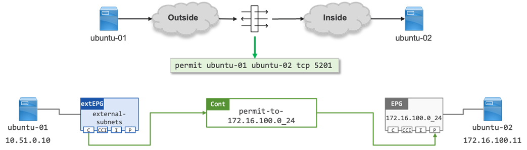
Note: A contract allows connections to established from the Consumer EPG to the Provider EPG matching the ports specified in the contract filter. By default, a contract is “applied in both directions” with “reverse filter ports” allowing the return traffic from the Provider EPG to the Consumer EPG.
Contract Components
Contracts are made up of mapped policies as shown in Figure 4. The ACI administrator should define a structured naming convention to aid troubleshooting. An example of such naming structure is discussed below.
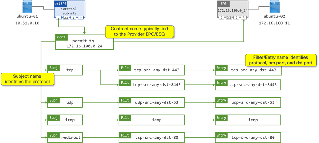
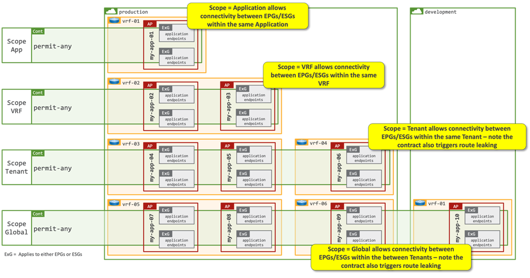
● Contract name: the contract name should provide relevance to the function of the contract. In the above example, the contract name identifies that it will permit traffic to the “172.16.100.0_24” EPG. The name of the consumer EPG is not specified in the contract name; therefore it is expected that there may be one or more consumers of the contract. The contract definition includes a “Scope” option which determines the relevancy of the contract:
● Scope Application: A contract will only program rules between EPGs/ESGs that are defined within the same Application Profile. Use of the same contract across other application profile EPGs/ESGs will not allow for crosstalk between them.
● Scope VRF (default): A contract will program rules between EPGs/ESGs that are defined within the same VRF. Use of the same contract across other EPGs/ESGs within the same VRF will allow crosstalk between the EPGs/ESGs.
● Scope Tenant: A contract will program rules between EPGs/ESGs that are defined on one or more VRFs within the same tenant.
● Scope Global: A contract will program rules between EPGs/ESGs across any tenant/VRF within an ACI fabric.
A contract is made up of one or more contract subjects.
● Contract subject: the contract subject should identify the protocols allowed to communicate with the provider EPG/ESG. In the above example there are contract subjects for TCP, UDP and ICMP. There is also a contract subject “redirect” which contains the filters identifying which flows will be redirected to a L4-7 device by way of a Service Graph.
The contract subject identifies how the contract filters are applied:
● Apply in both directions (default): The filter protocol and the source and destination ports are deployed exactly as defined for both consumer-to-provider and provider-to-consumer directions.
● Reverse ports: This option should be used always when Apply Both Directions is enabled. The filter protocol and the source and destination ports are deployed exactly as defined for the consumer-to-provider direction, and with source and destination ports reversed for the provider-to-consumer direction.
● Action: Permit or Deny traffic on the given ports.
A contract subject is made up of one of more contract filters.
● Contract Filters: the contract filter should identify the source and destination ports that opened between the consumer and provider EPG/ESG. In the above example there is a contract filter for “tcp-src-any-dst-443” which is mapped to a corresponding contract filter entry with the same name. A contract filter is made up of one or more contract filter entries.
● Contract Filter Entry: the contract filter entry identifies the source and destination ports programmed into the TCAM on the Nexus 9000 series switches. In the above example there is a contract filter entry for “tcp-src-any-dst-443”, this entry will program (open) “any” tcp port on the consumer EPG/ESG, and program (open) tcp port 443 on the provider EPG/ESG. The source port always identifies the port(s) open on the consumer EPG/ESG, and the provider port always identifies the port(s) open on the provider EPG/ESG.
Note: It is recommended to use explicit naming conventions for contracts, subjects, filters, entries to provide clarity on how the contract will program the TCAM hardware. As noted above, the Scope of the contract is critical to understanding which EPGs/ESGs the contract will be applied to. If ACI administrators choose to re-use contracts without understand the Scope applied to the contract it is possible to invoke unintended communication and route leaking.
Service Graphs
As described in the contract section, the contract subject allows administrators to apply a service graph. A service graph is an ACI function that can steer traffic to a L4-L7 device so that additional services can be provided for traffic between different security groups (extEPGs, EPGs, ESGs and vzAny). A service graph is an ACI function that can steer traffic to a L4-L7 device so that additional services can be provided for traffic between different security groups (extEPGs, EPGs, ESGs and vzAny). A common requirement is having a firewall at the edge of the network between networks domains. Traditionally, L4-L7 services are deployed in the routed path, which can often pose a bottleneck. Through service graphs, the Cisco ACI fabric can redirect traffic between security zones without the need for the L4-L7 device to be the default gateway for the servers, or the need to perform traditional networking configuration such as VRF sandwiching, or VLAN stitching. Cisco ACI can selectively send traffic to L4-L7 devices based, for instance, on the protocol and the layer 4 port.
Note: For more information about service graph design and configuration, see: https://www.cisco.com/c/en/us/solutions/collateral/data-center-virtualization/application-centric-infrastructure/white-paper-c11-739971.html
vzAny
ACI supports a logical “catch-all” construct, which is known as vzAny. Any contract which is applied to vzAny is automatically applied to all endpoints within a given VRF, i.e., when vzAny provides a contract it means that all EPGs, ESGs, and extEPGs are providers of the same contract, and when vzAny consumes a contract, it means that all EPGs, ESGs, and extEPGs are consumers of the same contract.
Note: vzAny cannot be a contract provider in a shared services design.
vzAny is often used to enable open communication within a VRF by providing and consuming the default contract from tenant common. Whilst this is a valid design, it does raise a potential security consideration as vzAny will also be applied to any external EPGs as shown in Figure 6.
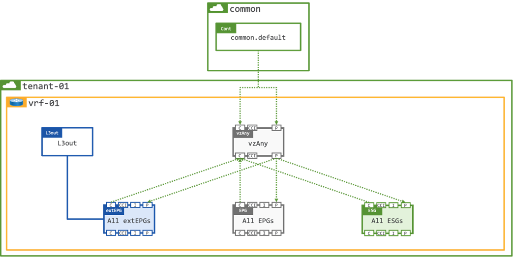
The potential issue is that you will have also allowed traffic from any remote subnet to any workload on the fabric which may or may not be the intended outcome.
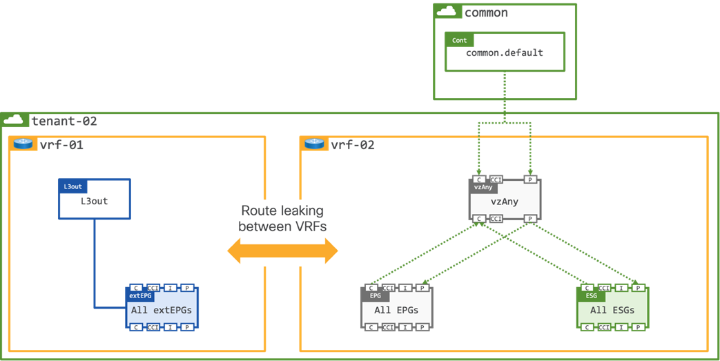
To mitigate the potential security risk of opening external connectivity to all workloads on the VRF an option is to create 2x VRFs within the tenant, one VRF is external facing, and one VRF is internal facing. Each tenant would have their own dedicated L3Out with route leaking configured between the external and internal VRFs as shown in Figure 7.
Note: The contract Scope would need to be modified to Tenant as it will be applied between VRFs in the same Tenant.
The final option to mitigate any potential security risk that vzAny could pose is to create a Shared L3Out in a dedicated shared-services tenant. The shared L3Out would provide inbound/outbound routing for all tenants on the fabric, and as per the previous example, route leaking would be enabled between the external shared-services VRF, and the internal tenant VRF.
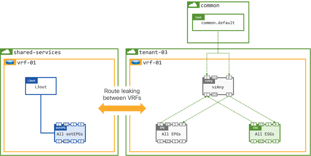
Note: The contract Scope would need to be modified to Global as it will be applied between VRFs in different Tenants.
Understanding route-leaking
ACI provides the ability to leak routes between VRFs which are configured both within the same tenant (Figure 9) or between VRFs which are configured in different tenants (Figure 10).
The use case of where multiple VRFs use the same L3Out is known as a “Shared L3Out”. The VRF providing the Shared L3Out can be configured either in a dedicated tenant or within tenant common. The decision where to create the shared L3Out (dedicated tenant or tenant common) is typically driven by security considerations. A VRF in tenant common can be consumed by any other tenants directly, which means there is no need to configure route leaking, whereas a VRF in a dedicated tenant must be explicitly configured with route leaking between VRFs. Therefore, a shared L3Out in a dedicated VRF can be considered a more secure design.
In this design guide, the shared L3Out exists in a dedicated “shared-services” tenant.
The VRF providing the shared L3Out connectivity contains both external routes and routes from the “internal” tenant VRFs, therefore subnets must be unique and non-overlapping. The routing tables in the “internal” VRFs can be dramatically simplified as they only need to contain the local Bridge Domain (SVI) subnets, and a default route shared from the shared-services VRF.
Route leaking for EPGs
Route leaking for EPGs is triggered by the instantiation of a contract between an EPG and an extEPG. The “shared route control subnet” and “shared security import subnet” flags on the extEPG of the external VRF control the leaking of routes, and the leaking of security controls (pcTags) to the “user” VRFs. Leaking of routes from the “user” VRF to the external VRF requires that the Bridge Domain be configured as “advertised” and “shared.”
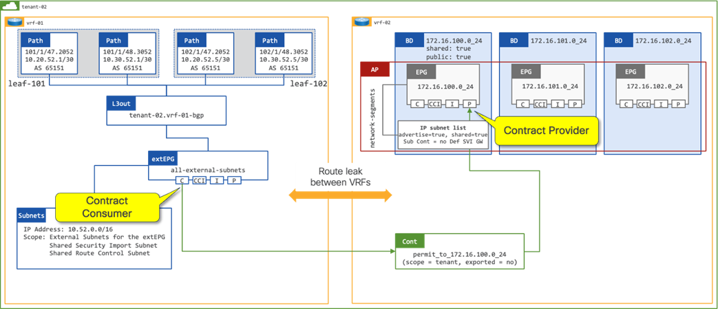
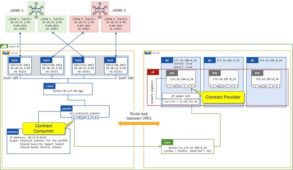
Route Leaking with EPG as the Contract Provider
In figure 11, a contract is in place between the extEPG in vrf-01 and the 172.16.100.0_24 EPG in vrf-02. The contract is provided by the 172.160.100.0_24 EPG and consumed by the extEPG 10.52.0.0_16. The extEPG classifies the external subnet 10.52.0.0/16 and leaks both the route and the pcTag of the extEPG from vrf-01 to vrf-02.
When the extEPG is configured as the contract consumer and the EPG configured as the contract provider, the administrator must configure the default gateway under the EPG to leak the route from the provider VRF to the consumer VRF.
The scope of the contract must be configured as “Tenant” to allow communication between different VRFs within the same tenant.
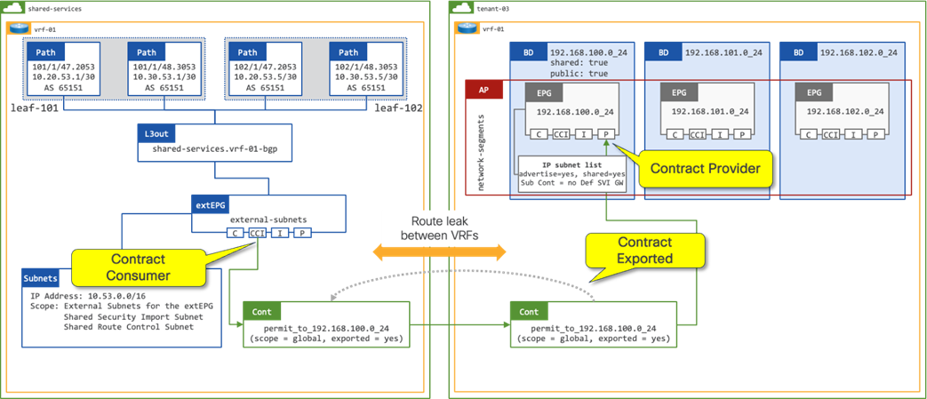
In a shared services design (Figure 12) where there is the requirement for route leaking between VRFs in different tenants, the administrator must configure the following options:
● Contract Scope must be set to Global
● Contract must be configured on the extEPG as a Consumed Contract Interface
Cisco Catalyst SD-WAN Building Blocks
Understanding SD-WAN Overlay
This section is optional if the reader is already familiar with Cisco Catalyst SD-WAN and its Cloud OnRamp for Multicloud. It aims to provide the reader with fundamental understanding of the SD-WAN building blocks that are involved in this design guide.
The Cisco Catalyst SD-WAN solution is based on the principle of separating the control and data planes of the WAN. The control plane manages the rules for routing traffic through the overlay network, while the data plane securely transports the actual data packets between the WAN Edge.
A virtualized data plane (overlay network) is provided by physical and virtual routers. These nodes are considered WAN Edge.
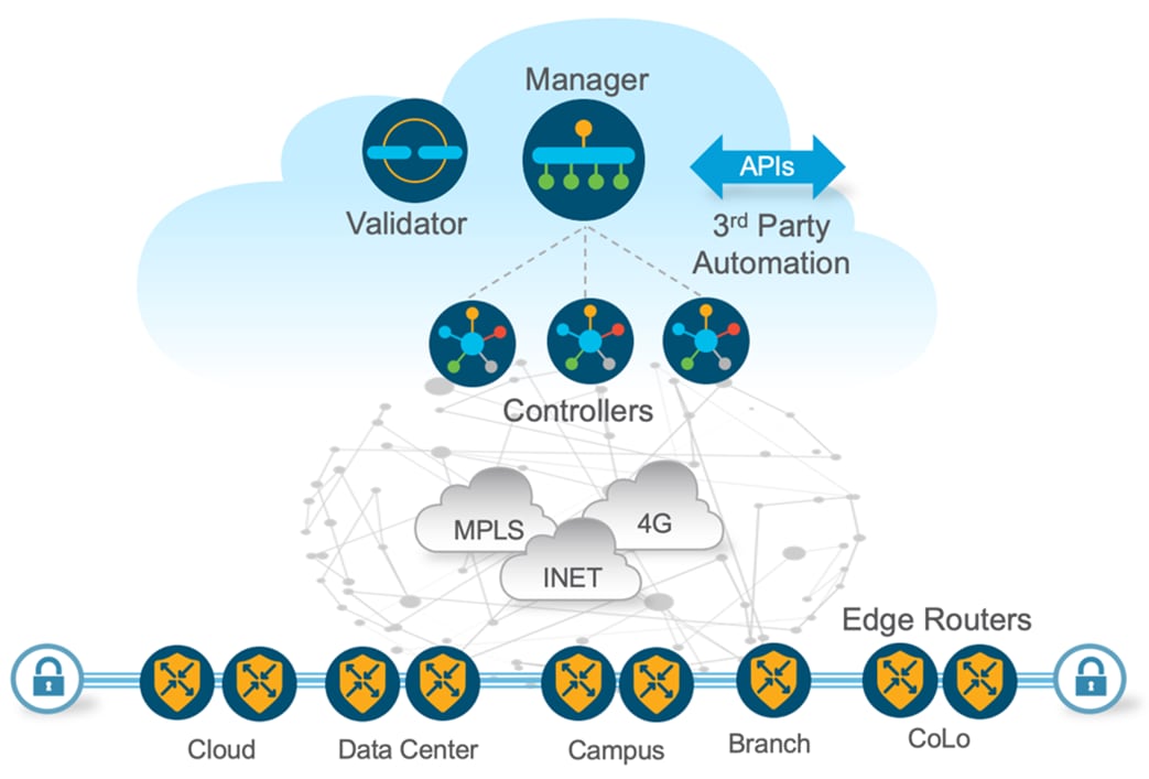
SD-WAN Centralized Control Plane
The centralized SD-WAN Controllers manage all routing and maintain the overlay connections following a model similar to the "route reflector" functionality in BGP. Controllers have all the information about the network and share relevant pieces of it with all WAN Edge so that they build connectivity based on centralized control policies configured by the administrator. Policies are important concept in CatalystSD-WAN. Control policy is the equivalent of routing protocol policy, and data policy is equivalent to what are commonly called access control lists (ACLs) and firewall filters. Cisco Catalyst SD-WAN policy design differentiate between centralized and localized policy. In short, centralized policy is provisioned on the centralized Cisco SD-WAN Controllers in the overlay network, and the localized policy is provisioned on Cisco IOS XE Catalyst SD-WAN devices, which sit at the network edge between a branch or enterprise site and a transport network, such as the Internet, MPLS, or metro Ethernet.
All Controllers will have up-to-date info about WAN Edge, in the event of failures in the WAN Edge, the Controllers update the route table in the WAN Edge to reroute the traffic to the available paths.
In addition to the Controllers, the SD-WAN control plane also includes the SD-WAN Validator. The main role of the Validators is to automatically identify and authenticate all other WAN Edge when they join the overlay network. This is achieved by the network administrator providing a list of WAN Edge which are expected to join the network. As such, the Validators also assist in the discovery and on-boarding of new WAN Edge in the overlay.
The Catalyst SD-WAN Manager provides centralized Network Management System. The Manager centralizes provisioning, management, and monitoring functions for the SD-WAN network with an intuitive, easy-to-use graphical dashboard. The Manager also offers these capabilities via a northbound REST API interface, which can be programmatically consumed by other systems such as Orchestration, Service Assurance, etc.
Note: This design guide does not cover the deployment of the controllers. For more information about controller deployment, the reader may use the following documentation: https://www.cisco.com/c/en/us/td/docs/routers/sdwan/configuration/sdwan-xe-gs-book/cisco-sd-wan-overlay-network-bringup.html.
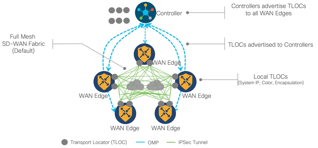
SD-WAN Data Plane
The data plane communication in the SD-WAN is based on point-to-point tunnels established between the WAN Edge. A TLOC, or Transport Location, is the attachment point where a WAN Edge connects to the WAN transport network. A TLOC is uniquely identified and represented by a three-tuple, consisting of system IP address, link color, and encapsulation (Generic Routing Encapsulation - GRE, or IPsec). TLOCs are also used to identify the next-hop in the OMP (Overlay Management Protocol) route advertisements. When a WAN Edge sends an advertisement to Controller for a VPN prefix, it includes its TLOC(s) asnext hopnext hop(s) for the route.
Note: Please refer to section Understanding Overlay Management Protocol to get familiar with OMP.
Cisco SD-WAN builds an overlay WAN network that operates over standard network transport services.
Understanding SD-WAN Segmentation
Cisco Catalyst SD-WAN network segmentation is implemented by using the Virtual Private Network (VPN) concept. It logically divides the overlay fabric into multiple end-to-end virtual network segments (similar to VRFs). Cisco SD-WAN segmentation is done on the WAN Edge, and the segmentation information is carried in the packets in the form of a unique VPN-Identifier (VPN-ID a.k.a. VPN label). A per-VPN routing table is maintained for a complete control plane separation. The use of embedded VPN labels in the packets allows a segmented connectivity across the overlay fabric without reliance on the underlay transport, hence achieving underlay transport independence. This is what allows the solution to be transport agnostic.
In Catalyst SD-WAN, the VPN ID concept equates VPNs to VRFs, assigning each a unique four-byte identifier ranging from 0 to 65535, with specific IDs like 0 and 512 reserved for internal use, thus capping the maximum configurable VPNs at 65525. Each VPN is isolated from one another, and each have their own forwarding table. An interface or subinterface is explicitly configured under a single VPN and cannot be part of more than one VPN. Labels are used in OMP route attributes and in the packet encapsulation, which identifies the VPN a packet belongs to.
These VPN-IDs, carried as labels across the SD-WAN fabric, ensure efficient and secure routing by maintaining isolated network segments, enabling scalable and flexible network traffic management for modern enterprises:
● VPN 0 is the transport VPN, containing interfaces that connect to the WAN transports, both public and private. Secure DTLS/TLS connections to the Controller, Manager, and Validator are initiated from this VPN. To establish the control plane and allow IPsec or GRE tunnels to reach the WAN Edge, static or default routes or a dynamic routing protocol need to be configured within this VPN for appropriate next-hop information.
● VPN 512 is the management VPN, handling the out-of-band management traffic to and from the Cisco Catalyst SD-WAN WAN Edge. This VPN is ignored by OMP and is not carried across the overlay network.
In addition to the default VPNs that are already defined, one or more service-side VPNs need to be created that contain interfaces that connect to the local-site network and carry user data traffic. It is recommended to select service VPNs in the range of 1-511. Service VPNs can be enabled for features such as OSPF or BGP, Virtual Router Redundancy Protocol (VRRP), QoS, traffic shaping, or policing. Routes from the local site can be advertised to other sites as service VPN routes by OMP, which is sent to the SD-WAN Controllers and redistributed to the other WAN Edge in the network. In the data path, Ingress WAN Edge apply VPN labels before performing IPSec encryption and egress WAN Edge use VPN labels to perform route lookup in the appropriate VPN routing table after the packet had been decrypted.
This design guide explains how to take advantage of the segmentation capabilities offered by SD-WAN and ACI, through use of VPNs and VRFs. Network prefix information is provided by ACI so that the SD-WAN solution can ensure isolation and end-to-end connectivity within the fabric. Route policy can be configured at the boundaries of both ACI and SD-WAN, allowing the administrator to control which network prefix information is exchanged. VPNs allow maintaining the isolation of tenants shared via L3-out. L3-out on leaves exchanges routes with WAN edges, and they can advertise them to SD-WAN via OMP.
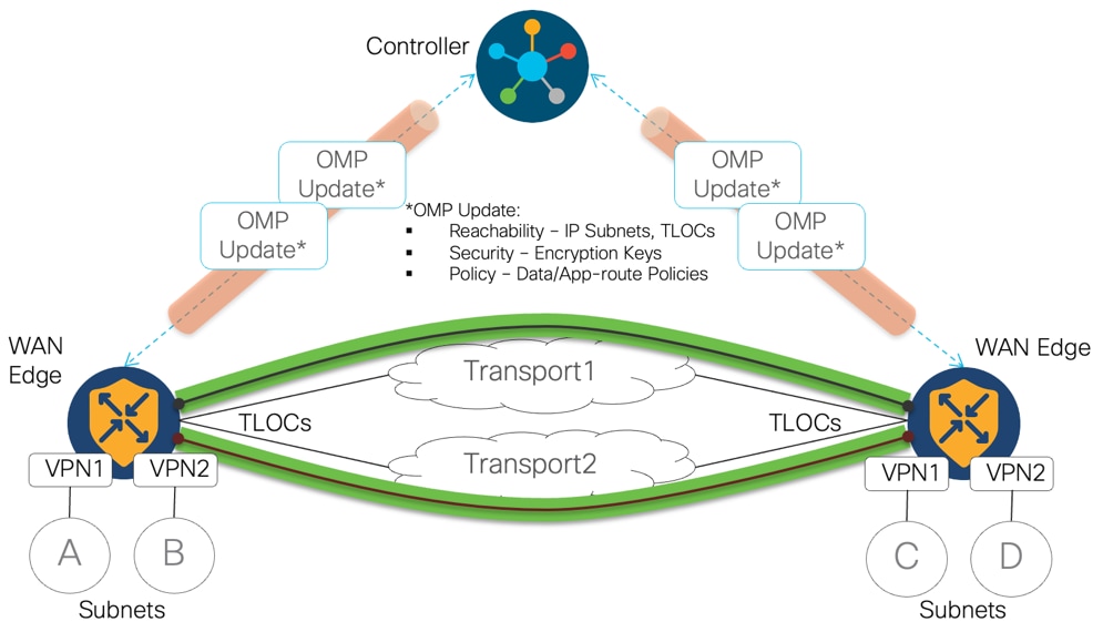
Understanding Overlay Management Protocol
Overlay Management Protocol (OMP) is a routing protocol that manages the SD-WAN overlay network. OMP runs between the Controllers and the WAN Edge and carries only control plane information. The Controller processes the routes and advertises reachability information learned from these routers to other WAN Edge in the overlay network.
OMP provides L3VPN service similar to BGP L3VPN for Unicast and Multicast IP traffic, and heavily leverages concepts, encoding and procedures from the same protocol. The introduction and use were dictated by the idea of significantly simplified protocol to leverage the network being operated by single administrative domain and under a software defined management and control plane. OMP runs on TCP inside the TLS/DTLS control plane connections and carries the routes, next-hop information, cryptographic keys, and policy information needed to establish and maintain the overlay network.
OMP automatically redistributes the following types of routes that are reachable locally, either directly or via a downstream router:
● connected
● static
● OSPF Intra and Inter area routes
● EIGRP
To avoid the potential of routing loops and less than optimal routing, redistribution of following types of routes requires explicit configuration:
● BGP
● OSPF external routes.
In order to avoid propagating excessive routing information to downstream routers attached to WAN edges, routes learnt via OMP are not automatically redistributed to downstream routers but can be enabled if desired. This allows for flexible routing design and, in the documented design, ensure an easy and isolated routing information exchange.
The Controller maintains a centralized route table that stores the route information, called OMP routes, including VPN awareness to support network segmentation. The Controller learns VPN routes from the WAN Edge and any other Controllers in the SD-WAN overlay network. Based on the configured policy, the Controller shares this route information with the WAN Edge in the network so that they can route traffic to each other.
Understanding the Use of Bidirectional Forwarding Detection
In enterprise networks, the convergence of business-critical applications onto a common IP infrastructure is becoming the norm. Given how critical data is these networks are typically constructed with a high degree of redundancy. While such redundancy is desirable, its effectiveness is dependent upon the ability of individual network devices to quickly detect failures and reroute traffic to an alternate path. The detection times in existing protocols are typically greater than one second, and sometimes much longer. For some applications, this duration is too long to be useful. Every SD-WAN Tunnel has got BFD protocol built-in to check the tunnel liveness and performance of the tunnel.
On Cisco WAN Edge, BFD is automatically started between peers and cannot be disabled. It runs between all WAN Edge in the topology and is encapsulated in SD-WAN tunnels and across all transports. BFD operates in an echo mode, which means when BFD packets are sent by a WAN Edge, and the receiving WAN Edge returns them without processing them. Its purpose is to detect path liveliness. On top of that, it can also perform quality measurements for application-aware routing, such as loss, latency, and jitter. BFD is used to detect both black-out and brown-out scenarios.
The use of tunnels with BFD sessions in SD-WAN provides visibility into intermediate networks, which are often considered “black boxes.” Monitoring BFD sessions allows administrators to gain valuable insight into the CSP and intermediate transport providers service level agreements (SLAs).
The use of BFD is not limited to datacenter to cloud connectivity. It is also used between virtual routers present in different cloud regions, through AWS global backbone with AWS Cloud WAN), and for site-to-site connectivity.
Understanding SD-WAN Cloud OnRamp (CoR) for Multicloud Functionality
Catalyst SD-WAN The goal of SD-WAN Cloud OnRamp is to simplify and automates the process of connecting on-premises environments to the cloud, and to help ensure that the customer experience and application experience, connectivity and security are the same in the cloud as they are on-premises. security requirements are provided holistically. This embedded functionality delivers unified policy across all major cloud service providers (e.g., Amazon Web Services, Google Cloud, and Microsoft Azure), optimal application experience with Software-as-a-Service (SaaS) optimization, and automated, cloud-agnostic branch connectivity with Multicloud and Cloud Interconnect (Megaport and Equinix).
Cloud OnRamp for Multicloud automates and seamlessly connects enterprise and on-prem networks to multiple cloud service provider networks, it allows the SD-WAN fabric and policy to be extended into the cloud infrastructure. It provides automated workflow to normalize the netops/cloudops connectivity experience across different applications/workloads hosted in the public cloud.
Note: Cloud gateways include different numbers of virtual routers via Cloud onRamp workflow. Depending on the cloud providers, in AWS workflow, the number is constant – two virtual routers in two separate availability zones.
For Azure and GCP, the number can be defined by the user and the decision should be made based on the network needs.
Each Cisco Catalyst SD-WAN virtual router in the transit VPC builds tunnels to the AWS Transit Gateway (TGW) or Cloud WAN Core Network Edge (CNE). Both IPSec and GRE tunnels can be used between Cisco Catalyst SD-WAN virtual routers and AWS networking instance. The choice for IPSec or GRE tunnels depends on customer requirements such as required throughput performance and security. Amazon VPCs are connected to TGW/CNE via VPC Attachments. Similar designs are possible with Azure using Virtual WAN (vWAN) and Google Cloud using Network Connectivity Center.
In this design guide, the SD-WAN Cloud OnRamp is leveraged to and within the cloud. The industry is gravitating towards AWS Cloud WAN to provide for centralized network functions. This allows the user to easily associate and manage cloud accounts, deploy, and configure virtual routers, and create tags that serve as segments in the Cloud WAN routing tables.
Whilst this document describes working with Cloud WAN, the same can be achieved with the TGW solution. Possibilities to use other Considerations to connect to other Cloud Service Providers (such as Microsoft Azure, Google Cloud) are described in SD-WAN Design Considerations - VPN Segmentation and Intent Management section.
SD-WAN Design Considerations
The following topics should be considered when designing hybrid cloud architectures using this design guide.
SD-WAN Transport
The connectivity between ACI to AWS can be Internet, private connectivity of AWS Direct Connect by SDCI provider (Equinix, Megaport), private connectivity of AWS Direct Connect by regional MPLS provider or any combination of the above. With multiple transports, SD-WAN can set up multiple SD-WAN tunnels and perform ECMP as default behavior. Transport Color restrict option is recommended to prevent attempts to establish SD-WAN tunnels and BFD sessions to TLOCs with different colors.
Note: For detail steps of configuring AWS Direct Connect as SD-WAN Transport, see:
SD-WAN Application performance optimization
Enhanced Application-aware routing (eAAR) can route the application to the WAN links that support the required levels of packet loss, latency and jitter defined in an application’s SLA, by introducing inline data that allows for more accurate and detailed measurements of these metrics. In the face of network brownouts or software failures, it can automatically activate the policy that redirects traffic to the best available path with improved SLA switch-over speed.
VPN Segmentation and Intent Management
SD-WAN VPN segmentation is being used to extend VRFs from ACI to SD-WAN fabric. Furthermore, the Intent Management in SD-WAN Cloud OnRamp workflow enables connectivity between SD-WAN VPNs and VPCs.
This design guide primarily focuses on SD-WAN Cloud OnRamp AWS integration, each attachment in AWS TGW/CNE is associated with one route table, by creating multiple VPN attachments or connect attachments to the TGW/CNE, it is extending SD-WAN VPNs from on-premises network into AWS Cloud infrastructure.
Other cloud service providers do not provide the native capability of extending VRF segmentations from on-prem sites to the cloud infrastructure, for example Azure allows to create different route tables in vHub and associate each VNET to dedicated route table, but it is not beneficial since the BGP peering from NVA to vHub can only be established with the default route table, can not form multiple BGP peers to learn with different route table. To achieve VPN segmentation in Azure Cloud, the alternative approach is to deploy Catalyst 8000V in Transit VNET, run SD-WAN with on-prem sites, run IPsec tunnel/BGP to Azure VPN gateway in host VNET, therefore, to extend VPN segmentation all the way to the host VNET.
Overlapping IPs
In case of overlapping IP addresses between ACI VRFs and Amazon VPCs, the administrator can configure service-side NAT on the WAN Edge so that data traffic is translated before entering the overlay tunnel of the transport VPN. Both dynamic and 1:1 static NAT on the service-side VPN, can be provisioned by a centralized data policy on the Controller. The policy directs data traffic with the desired prefixes to the service-side NAT.
Route leaking
If there are common services that multiple VPNs need to access, SD-WAN inter-service route leaking provides the ability to leak selective routes between service VRFs back to the originating device on the same site.
MTU
It is recommended you use default MTU 1500B if WAN transport is Internet and configure to 9216B if using private WAN support jumbo MTU.
On WAN Edge, the SD-WAN BFD automatically performs PMTU discovery on each transport connection (that is, for each TLOC, or color).
WAN Edge need configure the SD-WAN tunnel encapsulation. The encapsulation can be either IPsec or GRE. For IPsec encapsulation, the default IP MTU is 1442 bytes, and for GRE it is 1468 bytes.
The fragmentation/reassembly is supported on WAN Edge, but network design should try to avoid it as it is going to significantly have performance impact.
High Availability
Device level high availability (HA) is achieved by connecting a pair of Catalyst WAN Edge (in this case two Catalyst 8500 are used) to a pair of ACI leaf switches. Within each cloud region, a pair of Catalyst 8000V routers provides HA in the transit VPC. eBGP on the Catalyst 8500 service VPN side is used to detect the network failure toward the ACI border leaf, to switchover traffic to the remaining active Catalyst 8500, similarly eBGP on the C8KV service VPN side is used to detect the network failure toward TGW/CNE to switchover traffic to the remaining active C8KV. As alluded earlier, ECMP or eAAR will ensure network traffic HA in SD-WAN overlay.
Performance
To facilitate different bandwidth requirements for the datacenter to public cloud, different platforms and licensing are available. The Catalyst 8500 has 4 products models to offer SD-WAN IPsec throughput with 1400B from 20 Gbps, up to 350 Gbps, see the Cisco Catalyst 8500 Series Edge Platforms Data Sheet (Table 5a) for details.
While Cisco C8000V is a virtual form factor router hosted in AWS, the throughput performance is highly dependable on the hosting EC2 instances, currently the largest EC2 instance hosting C8000V is c5n.18xlarge, which supports up to 30 Gbps SD-WAN IPsec throughput. If there is a requirement to support high bandwidths, for example 100 Gbps links, horizontal data plane scaling is a common deployment best practice, which means the user needs to manually bring up additional C8000V instances in the transit VPC and connect attachment to TGW/CNE. In such case, the Catalyst 8500 would do ECMP to load share traffic across all C8000V instances to achieve the desired total throughput.
DC as Transit
The Catalyst 8500 in the data center can be deployed as SD-WAN Hub to aggregate regional branch sites while acting as DC border node performing the ACI to SD-WAN Cloud OnRamp function. There can be two different scenarios for the branch sites:
● The first scenario is that branch has no direct Cloud access, all branch traffic is backhauled to the DC, and it accesses the cloud through DC C8500. The throughput performance and scale capacity needs to be carefully planned on the C8500 to ensure it is capable of handling both branch traffic and ACI traffic. Horizontal data plane scaling is a common deployment best practice, which involves provisioning multiple SD-WAN routers at the DC. It allows certain spoke (branch) routers to form SD-WAN tunnels to certain head-end (DC) routers. This can be done through Tunnel Groups. Another option is to deploy a separate C8500 as an WAN aggregation platform and a separate C8500 as an ACI to SD-WAN Cloud OnRamp device if there is significant amounts of ACI to Cloud traffic which justifies a dedicated SD-WAN Edge.
● The second scenario is that branches have a direct cloud access and use the DC transit path as a backup, which can be controlled by the SD-WAN traffic policy.
Cloud as Transit for Inter-Region DC
Cisco Catalyst SD-WAN with AWS Cloud WAN integration allows inter-region DC communication using AWS global backbone.
Connect ACI Tenants to SD-WAN Cloud OnRamp
ACI Configuration Overview
The following section for ACI explains how to set up external connectivity from an ACI fabric to a pair of SD-WAN routers (Catalyst 8500 Routers were used during design validation testing). The sub-interfaces on ACI border leaf switches are leveraged to allow for multiple VRFs over the same physical connections using a VRF-lite hand-off. In the configuration example below, interfaces Ethernet 1/47 and 1/48 on ACI leaf nodes 101 and 102 are used to provide connectivity to the WAN Edge. eBGP is configured to exchange route information.
It is assumed that there are multiple networks requiring external connectivity from the ACI fabric to the Cloud. It is further assumed that there are several existing tenants each with different external connectivity requirements. These tenants will be presented throughout the configuration section as they illustrate different brownfield environments.
● Tenant-01: 172.16.100.0/24, 172.16.101.0/24, 172.16.102.0/24
● Tenant-02: 172.16.100.0/24, 172.16.101.0/24, 172.16.102.0/24
● Tenant-03: 192.168.100.0/24, 192.168.101.0/24, 192.168.102.0/24
● Tenant-04: 192.168.200.0/24, 192.168.201.0/24, 192.168.202.0/24
Note that tenant-01 and tenant-02 have overlapping IP addresses. The purpose of this is to overcome such IP overlap requirement. These overlapping IP ranges are maintained in separate VRFs across the WAN. Also note that only the first network (e.g., 172.16.100.0/24, and 192.168.100.0/24) of each tenant is advertised to the SD-WAN routers. This is to more accurately represent a brownfield environment whereby not every network needs to be advertised externally. Should the administrator want to advertise, and provide communication to additional networks, the configuration steps for each first network can be replicated.
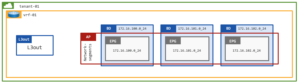
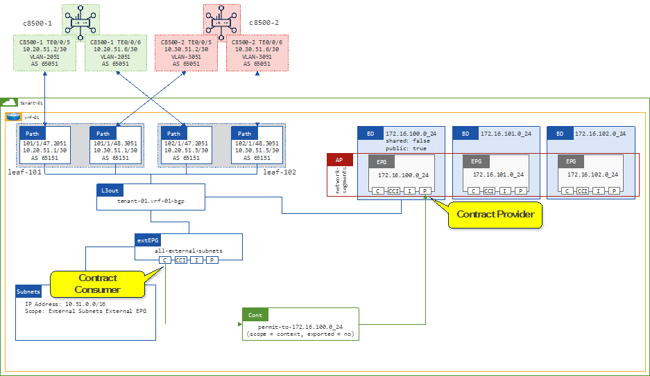
Tenant with Single VRF and Dedicated External Connectivity
This design represents a dedicated tenant in ACI, with a single VRF used for internal and external communication. The ACI tenant (tenant-01) has a single VRF (vrf-01) and 3x Bridge Domains (subnets), each with a single EPG (VLAN).
It is assumed that the ACI Tenant, VRF, Bridge Domains, and EPGs have been previously configured.
This design is common in scenarios whereby isolation between tenants is desired. Such as in ACI fabrics that are used by multiple organizations and or teams, administrators can make use of dedicated tenants.
Each dedicated tenant offers isolation and contains the needed networking constructs. Because of its isolated characteristics, each tenant typically has at least one or multiple VRFs. Each tenant also contains a dedicated L3Out to exchange route information with the outside for external communication if needed.
The configuration (above) will focus on establishing connectivity between the 172.16.100.0/24 subnet on the ACI fabric and the Public Cloud CIDR block 10.51.0.0/16.
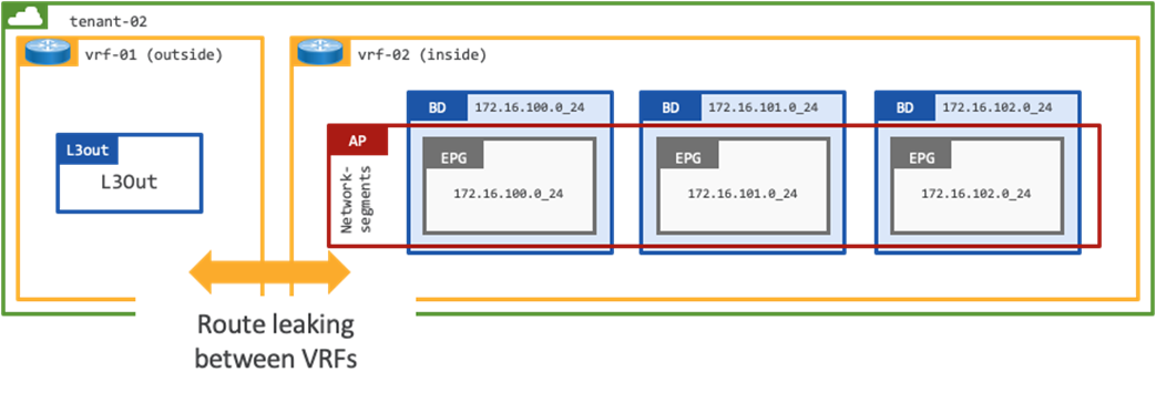
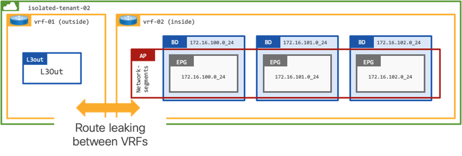
Tenant with Two VRFs and Dedicated External Connectivity
This design represents a dedicated tenant in ACI, where two VRFs are configured for internal and external route table separation:
● vrf-01 provides external connectivity
● vrf-02 provides internal connectivity
This is a shared services design within the scope of a tenant. Administrators can leverage shared external connectivity from multiple intra-tenant VRFs, for example the ACI administrator could add vrf-03 and determine which prefixes are leaked between the different VRFs.
It is assumed that the ACI Tenant, VRFs, Bridge Domains, and EPGs have been previously configured.
The configuration (above) will focus on establishing connectivity between the 172.16.100.0/24 subnet on the ACI fabric and the Public Cloud CIDR block 10.52.0.0/16.
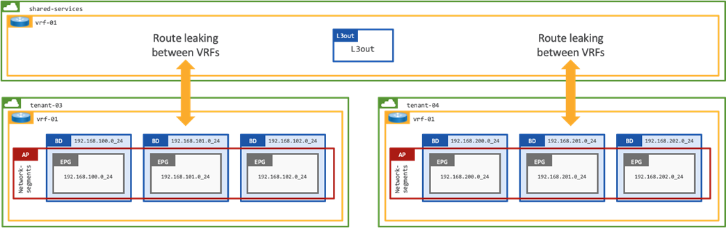
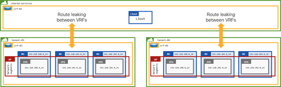
Shared-services Design for Multiple Tenants with Shared External Connectivity
This design represents a shared services model in ACI, whereby multiple tenants leverage shared services provided by another tenant.
The configuration section explains how to establish external connectivity between the 192.168.100.0/24 (tenant-03) and 192.168.200.0/24 (tenant-04) networks on the ACI fabric and the Public Cloud CIDR block 10.53.0.0/16. The configuration will also ensure that tenant-03 and tenant-04 are not able to communicate.
It is assumed that the ACI Tenants tenant-03 and tenant-04, VRFs, Bridge Domains, and EPGs have been previously configured.
Programmatic Configuration
To complement the written configuration guide below, the accompanying code is available to deploy all referenced configuration programmatically, using the APIC API: https://github.com/datacenter/Terraform-recipes-for-ACI/tree/ACISDWAN/ACI_SD-WAN_Cloud_Onramp_design_guide
Initial ACI Configuration
ACI Fabric Access Policies are used to configure parameters that relate to access into the fabric (i.e., configuring ports on leaf switches for servers, firewalls, network switches, and other devices). In addition, Fabric Access Policies are used to configure other parameters like, LLDP or CDP, LACP and more.
As the same physical connections are used to connect each ACI tenant to the SD-WAN routers, several access policies only need to be configured once. Therefore, the configuration section for each design makes use of the configuration provided in this paragraph.
Note: Starting with APIC software version 5.2(7), APIC offers a new improved interface configuration method. This configuration section uses the traditional method, to ensure backward compatibility. The way the relevant objects are created in this section is functionally equivalent to the new interface configuration method.
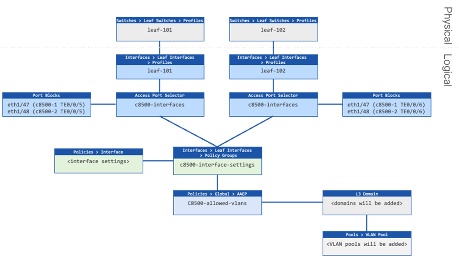
Figure 20 shows the objects to be created. It is assumed that there is already a Leaf Switch Profile for each border-leaf, and that it is associated with a Leaf Interface Profile. This is typically the case for any existing ACI fabric. If this deployment is done in a greenfield environment, or on a pair of new leaf switches, the administrator should first configure a leaf interface profile and switch profile for each leaf switch.
High-level Steps
1. Create an Attachable Access Entity Profiles (AAEP). This will allow VLANs to be deployed on the leaf switches interfaces, when VLAN pools are associated in a later step. (c8500-allowed-vlans)
2. Create an Interface Policy Group that contains the interface settings. (c8500-interface-settings).
3. Create two Leaf Interface Profiles that contain the Access Port Selectors with the interfaces connected to the SD-WAN routers. (c8500-interfaces)
Procedure 1. Create Attachable Access Entity profiles
Step 1. In the GUI Navigation pane, under Fabric, navigate to Access Policies > Policies > Global > Attachable Access Entity Profile.
Step 2. Right-click and select Create Attachable Access Entity Profile
Step 3. In the Create Attachable Access Entity Profile, perform the following actions:
a. In the Name field, enter the name for the Attachable Access Entity Profile. (c8500-allowed-vlans)
b. Uncheck the Association to Interfaces checkbox.
Procedure 2. Create Leaf Interface Policy Groups
Step 1. In the GUI Navigation pane, under Fabric, navigate to Access Policies > Interfaces > Leaf Interfaces > Policy Groups > Leaf Access Port.
Step 2. Right-click and select Create a Leaf Access Port Policy Group.
Step 3. In the Create a Leaf Access Port Policy Group, perform the following actions:
Step 4. In the Name field, enter the name for the Leaf Access Port Policy Group (c8500-interface-settings)
Step 5. In the Attached Entity Profile, select the previously created Attachable Access Entity Profile (c8500-allowed-vlans)
Procedure 3. Create Leaf Interface Profiles
Step 1. In the GUI Navigation pane, under Fabric, navigate to Access Policies > Interfaces > Leaf Interfaces > Profiles.
Step 2. Right-click the profile for the first border leaf switch (leaf-101) and select Create Access Port Selector.
Step 3. In the Create Access Port Selector window, perform the following actions:
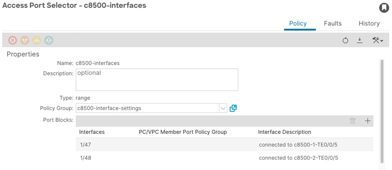
a. In the Name field, enter the name (c8500-interfaces).
b. In the Interface IDs field, provide the interface IDs of the interfaces connected to the SD-WAN routers (1/47,1/48).
c. In the Interface Policy Group field, select the previously created Leaf Access Port Policy Group (c8500-interface-settings).
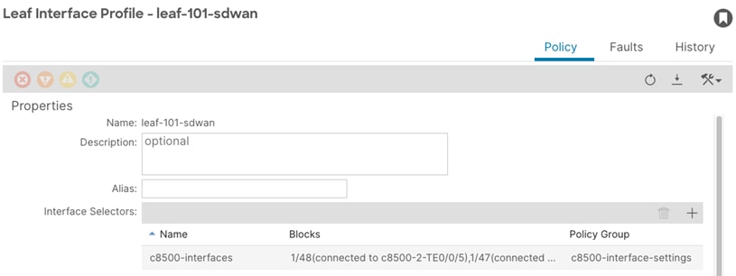
d. Optional: select the new Access Port Selector and double-click on the interface selector (c8500-interfaces). In this window, double-click on each interface and provide an interface Description. (connected to c8500-1 TE0/0/5, connected to c8500-2 TE0/0/5).
e. Right-click the profile for the second border leaf switch (leaf-102) and select Create Access Port Selector.
f. In the Create Access Port Selector window, perform the following actions:
i. In the Name field, enter the name (c8500 -interfaces).
ii. In the Interface IDs field, provide the interface IDs of the interfaces connected to the SD-WAN routers (1/47,1/48).
iii. In the Interface Policy Group field, select the previously created Leaf Access Port Policy Group (c8500-interface-settings).
g. Optional: select the new Access Port Selector and double-click on the interface selector (c8500-interfaces). In this window, double-click on each interface and provide an interface Description. (connected to c8500-1 TE0/0/6, connected to c8500-2 TE0/0/6).
Tenant with Single VRF and Dedicated External Connectivity (tenant-01)
This design is commonly used in environments where isolation is required. A dedicated L3Out is configured within the tenant itself. The networks advertised from the ACI border leaf switches to the WAN routers will enter a dedicated VPN, providing end-to-end segmentation in the SD-WAN domain.
Figure 21 shows the external connectivity from the border leaf switches to the SD-WAN routers for tenant-01.
High-level Steps
1. Create a VLAN pool for the VLAN used on the sub-interfaces connected to the SD-WAN routers. (tenant-01.vrf-01-bgp)
2. Create a L3 Domain for the L3Out. (tenant-01.vrf-01-bgp)
3. Link the L3 Domain to the Attachable Access Entity Profile.
4. Create a L3Out for the BGP adjacencies to the SD-WAN routers. (tenant-01.vrf-01-bgp)
5. Add the L3Out to the bridge domain. (172.16.100.0/24)
6. Create Filters to determine which type of traffic is allowed between the external and internal networks. Example filters are used. (icmp-src-any-to-dst-any and tcp-src-any-to-dst-any)
7. Create Contracts. The subjects for these contracts will reference the previously created filters.
8. Provide the Contracts on the provider side EPGs.
9. Consume the Contracts on the extEPG on the shared L3Out to allow for external communication to traverse to the provider side EPGs.
Procedure 1. Create a VLAN pool
Step 1. In the GUI Navigation pane, under Fabric, navigate to Access Policies > Pools > VLAN.
Step 2. Right-click and select Create VLAN Pool.
Step 3. In the Create VLAN Pool screen, perform the following actions:
a. In the Name field, enter the name for the VLAN pool. (tenant-01.vrf-01-bgp)
b. Set the Allocation Mode to Static Allocation.
c. Click the + sign to add a new Encap Block.
d. In the Description field, optionally provide a description (vlan to c8500-1)
e. In the Range fields, provide the VLAN to be used for sub-interface connected to c8500-1. (2051)
f. Click the + sign to add a new Encap Block for the VLANs to be used for sub-interfaces connected to c8500-2.
g. In the Description field, optionally provide a description. (vlan to c8500-2)
h. In the Range fields, provide the VLAN range to be used for sub-interfaces connected to c8500-2. (3051)
Procedure 2. Create a L3 Domain
Step 1. In the GUI Navigation pane, under Fabric, navigate to Access Policies > Physical and External Domains > L3 Domains.
Step 2. Right-click and click Create L3 Domain.
Step 3. In the Name field, enter a name for the L3 Domain. (tenant-01.vrf-01-bgp)
Step 4. In the VLAN Pool field, select the previously created VLAN Pool (tenant-01.vrf-01-bgp)
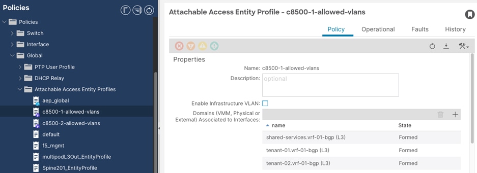
Procedure 3. Add a Domain to Attachable Access Entity profiles
Step 1. In the GUI Navigation pane, under Fabric, navigate to Access Policies > Policies > Global > Attachable Access Entity Profiles.
Step 2. Select the previously created attachable access entity profile. (c8500-1-allowed-vlans).
Step 3. In the Attachable Access Entity Profile window, perform the following actions:
a. In the Domains field, click the + sign and select the previously created Domain Profile. (tenant-01.vrf-01-bgp)
b. Repeat Step 2-3 for the attachable access entity profile used for the second wan router (c8500-2-allowed-vlans)
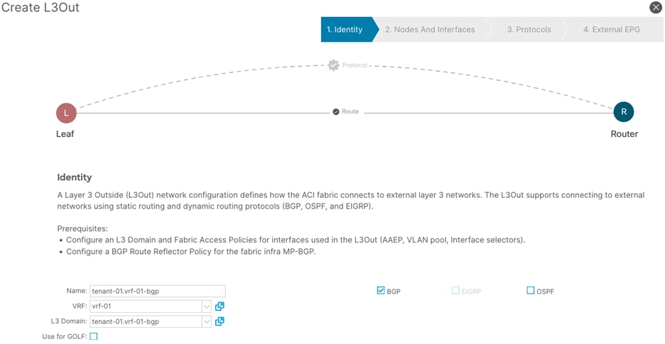
Procedure 4. Create a L3Out
Step 1. In the GUI Navigation pane, under Tenants (tenant-01) navigate to Networking > L3Outs.
Step 2. Right-click and select Create L3Out.
Step 3. In the Create L3Out wizard, perform the following actions:
a. In the Name field, enter the name. (tenant-01.vrf-01-bgp)
b. In the VRF field, select the VRF (vrf-01)
c. In the L3 Domain field, select the previously created L3 Domain (tenant-01.vrf-01-bgp)
d. Select the BGP checkbox.
e. Proceed to the next step of the wizard by clicking Next.
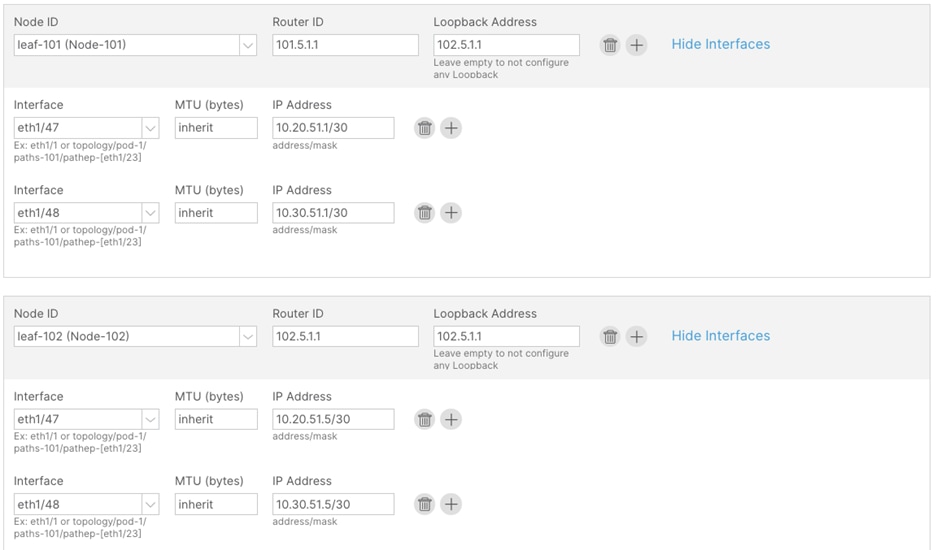
Step 4. In the Nodes and Interfaces window, perform the following actions:
a. In the Interface Types > Layer 3 section, select Sub-Interface.
b. In the Node drop-down list, select the first border leaf-node. (leaf-101)
c. In the Router ID field, enter the router ID. (101.5.1.1)
d. In the Interface drop-down list, select the interface connected to c8500-1. (1/47)
e. In the Encap Value, enter the VLAN for the connection to c8500-1 (2051)
f. In the IP Address field, enter the IP address. (10.20.51.1/30)
Step 5. Click the + sign to add a new interface.
a. In the Interface drop-down list, select the interface connected to c8500-2. (1/48)
b. In the Encap Value, enter the VLAN for the connection to c8500-2. (3051)
c. In the IP Address field, enter the IP address. (10.30.51.1/30)
d. In the Node field, click the + sign to add another node field.
Step 6. In the new Node field, perform the following actions:
a. In the Node drop-down list, select the second border leaf-node. (leaf-102)
b. In the Router ID field, enter the router ID. (102.5.1.1)
c. In the Interface drop-down list, select the interface connected to c8500-1. (1/47)
d. In the Encap Value, enter the VLAN for the connection to c8500-1 (2051)
e. In the IP Address field, enter the IP address. (10.20.51.5/30)
Step 7. Click the + sign to add a new interface:
a. In the Interface drop-down list, select the interface connected to c8500-2. (1/48)
b. In the Encap Value, enter the VLAN for the connection to c8500-2. (3051)
c. In the IP Address field, enter the IP address. (10.30.51.5/30)
Step 8. Confirm that all configuration has been provided and proceed to the next step of the wizard.
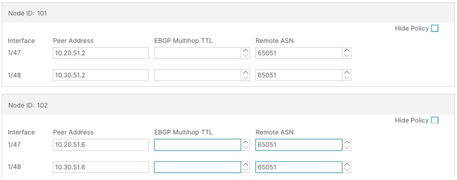
Step 9. In the Protocols window, perform the following actions:
a. In the Interface Policies field, enter the Peer Address and Remote ASN:
i. Node ID: 101 1/47, Peer Address (10.20.51.2) and the Remote ASN. (65051)
ii. Node ID: 101 1/48, Peer Address (10.30.51.2) and the Remote ASN. (65051)
iii. Node ID: 102 1/47, Peer Address (10.20.51.6) and the Remote ASN. (65051)
iv. Node ID: 102 1/48, Peer Address (10.30.51.6) and the Remote ASN. (65051)
Step 10. In the External EPG window, perform the following actions:
a. In the Name field, enter a name for the external EPG (external-subnets)
b. Uncheck the Default EPG for all external networks checkbox.

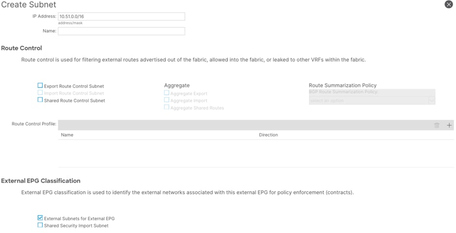
c. In the Subnets field, click the + sign to add a new subnet.
Step 11. In the Create Subnet window, perform the following actions:
a. In the IP Address field, enter the remote prefix. (10.51.0.0/16)
Note: The remote prefix represents an exact match on the VPC CIDR. For multiple VPCs, add additional remote prefixes.
b. Select External Subnets for External EPG.
Procedure 5. Add the L3Out to the Bridge Domain
Step 1. In the GUI Navigation pane, under Tenants (tenant-01), navigate to Networking > Bridge Domains > (172.16.100.0_24)
Step 2. In the bridge domain Policy tab, navigate to L3 Configurations.
Step 3. In the Associated L3 Outs field, click the + sign to add the previously created L3out.
Step 4. From the drop-down list, select tenant-01.vrf-01-bgp.
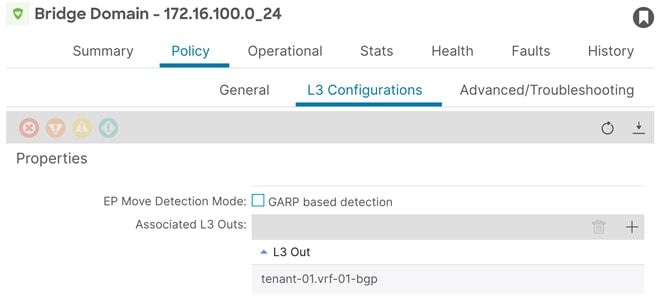
Note: The bridge domain shown in Figure 28 (172.16.100.0_24) is assumed as part of the existing brownfield configuration.
Allow Communication
Contracts, subjects, and their filters will be configured. This example configuration will provide example naming and configuration, to allow both ICMP and TCP traffic. This can be customized as per user requirements.
Procedure 6. Create filters
Step 1. In the GUI Navigation pane, under Tenants (tenant-01), navigate to Contracts > Filters.
Step 2. Right-click and select Create Filter.
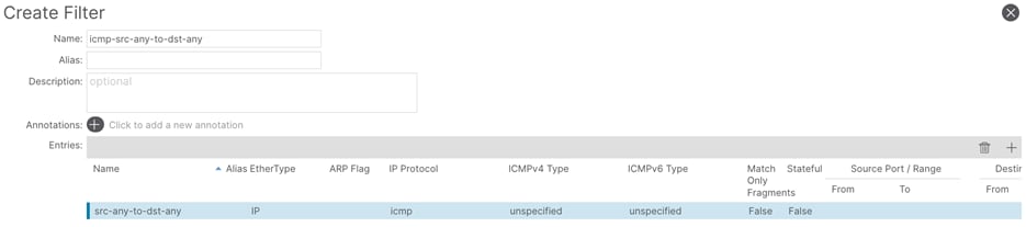
Step 3. In the Create Filter window, perform the following actions:
a. In the Name field, enter a name (icmp-src-any-to-dst-any)
b. In the Create Filter window, click the + button.
c. In the Entries field, perform the following actions:
d. In the Name field, enter a name (src-any-dst-any)
e. In the Ethertype drop-down list, select IP.
f. In the IP Protocol drop-down list, select ICMP.
g. Submit the configuration and proceed with the next step.
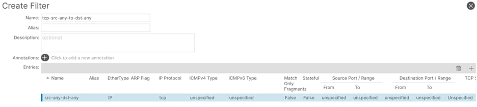
Step 4. In the Create Filter window, perform the following actions:
a. In the Name field, enter a name (tcp-src-any-to-dst-any)
b. In the Create Filter window, click the + button.
c. In the Entries field, perform the following actions:
i. In the Name field, enter a name (src-any-dst-any)
ii. In the Ethertype drop-down list, select IP.
iii. In the IP Protocol drop-down list, select TCP.
iv. Submit the configuration and proceed with the next step.
Procedure 7. Create contracts
Step 1. In the GUI Navigation pane, under Tenants (tenant-01), navigate to Contracts > Standard.
Step 2. Right-click and select Create Contract.
Step 3. In the Name field, enter a name. (permit-to-172.16.100.0_24)
Step 4. In the Scope field, select VRF.
Step 5. In the Create Contract window, click the + button to add a new subject.
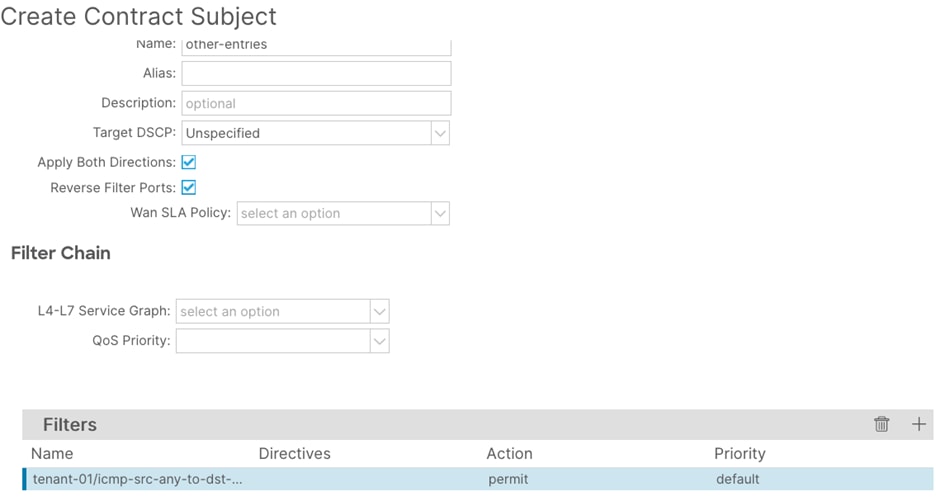
Step 6. In the Create Contract Subject window, perform the following actions:
a. In the Name field, enter a name for the subject (other-entries)
b. In the Filters window, click the + button.
c. In the Filters Name drop-down list, select the filter. (icmp-src-any-to-dst-any)
d. Click Update and proceed to the next step.
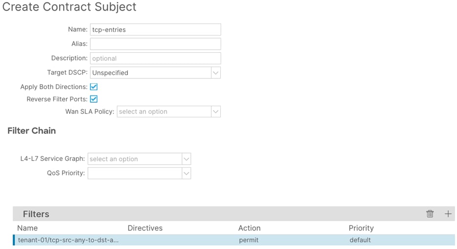
Step 7. In the Create Contract Subject window, perform the following actions:
a. In the Name field, enter a name for the second subject (tcp-entries)
b. In the Filters window, click the + button.
c. In the Filters Name drop-down list, select the filter (tcp-src-any-to-dst-any)
d. Click Update and proceed to the next step.
Step 8. In the Create Contract Subject window, confirm the configuration and click Submit.

Procedure 8. Provide the contract
Step 1. In the GUI Navigation pane, under Tenants (tenant-01), navigate to Application Profiles > Application > network-segments > 172.16.100.0_24.
Step 2. Right-click and select Add Provided Contract.
Step 3. In the Add Provided Contract window, select the contract created previously. (permit-to-172.16.100.0_24)
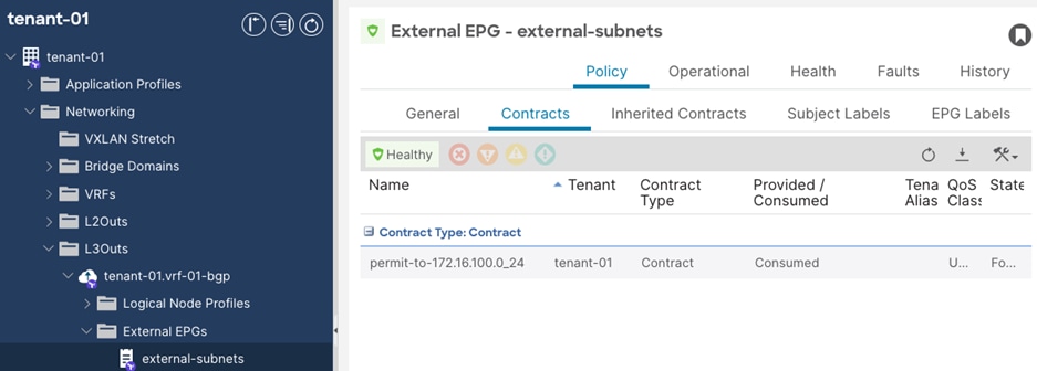
Procedure 9. Consume the contract
Step 1. In the GUI Navigation pane, under Tenants (tenant-01), navigate to Networking > L3Outs > tenant-01.vrf-01-bgp > External EPGs > external-subnets.
Step 2. In the External EPG window, navigate to Policy > Contracts.
Step 3. Click the Action button and select Add Consumed Contract.
Step 4. In the Add Consumed Contract window, select the previously created contract. (permit-to-172.16.100.0_24).
Tenant with Two VRFs and Dedicated External Connectivity (tenant-02)
This design is commonly used in environments where isolation is required. A dedicated L3Out is configured within the tenant itself. The L3Out is placed in a dedicated VRF for external connectivity. Other internal VRFs within this tenant can make use of this L3Out by leaking routes. The networks advertised from the ACI border leaf switches to the WAN routers will enter a dedicated VPN, providing end-to-end segmentation in the SD-WAN domain.
Figure 29 shows the external connectivity.
High-level Steps
1. Create a VLAN pool for the VLAN used on the sub-interfaces connected to the SD-WAN routers. (tenant-02.vrf-01-bgp)
2. Create a L3 Domain for the L3Out. (tenant-02.vrf-01-bgp)
3. Link the L3 Domain to the Attachable Access Entity Profile.
4. Create a L3Out for the BGP adjacencies to the SD-WAN routers. (tenant-02.vrf-01-bgp)
5. Create Filters to determine which type of traffic is allowed between the external and internal networks. Example filters are used. (icmp-src-any-to-dst-any and tcp-src-any-to-dst-any)
6. Create Contracts. The subjects for these contracts will reference the previously created filters.
7. Provide the Contracts on the provider side EPGs.
8. Consume the Contracts on the extEPG on the shared L3Out to allow for external communication to traverse to the provider side EPGs.
Procedure 1. Create a VLAN pool
Step 1. In the GUI Navigation pane, under Fabric, navigate to Access Policies > Pools > VLAN.
Step 2. Right-click and select Create VLAN Pool.
Step 3. In the Create VLAN Pool screen, perform the following actions:
a. In the Name field, enter the name for the VLAN pool. (tenant-02.vrf-01-bgp)
b. Set the Allocation Mode to Static Allocation.
c. Click the + sign to add a new Encap Block.
d. Optional: In the Description field, provide a description. (vlan to c8500-1)
e. In the Range fields, provide the VLAN to be used for sub-interface connected to c8500-1. (2052)
f. Click the + sign to add a new Encap Block for the VLANs to be used for sub-interfaces connected to c8500-2.
g. Optional: In the Description field, provide a description. (vlan to c8500-2)
h. In the Range fields, provide the VLAN range to be used for sub-interfaces connected to c8500-2. (3052)
Procedure 2. Create a L3 Domain
Step 1. In the GUI Navigation pane, under Fabric, navigate to Access Policies > Physical and External Domains > L3 Domains.
Step 2. Right-click and select Create L3 Domain.
Step 3. In the Name field, enter a name for the L3 Domain. (tenant-02.vrf-01-bgp)

Step 4. In the VLAN Pool field, select the previously created VLAN Pool (tenant-02.vrf-01-bgp)
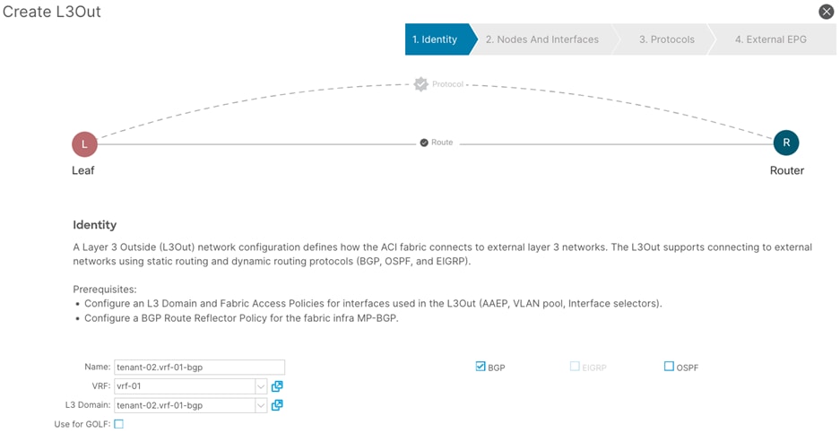
Procedure 3. Create a L3Out
Step 1. In the GUI Navigation pane, under Tenants (shared-services), navigate to Networking > L3Outs.
Step 2. Right-click and select Create L3Out.
Step 3. In the Create VRF wizard, perform the following actions:
a. In the Name field, enter the name. (tenant-02.vrf-01-bgp)
b. In the VRF field, select the existing VRF (vrf-01)
c. In the L3 Domain field, select the previously created L3 Domain (tenant-02.vrf-01-bgp)
d. Select the BGP checkbox.
e. Proceed to the next step of the wizard by clicking Next.
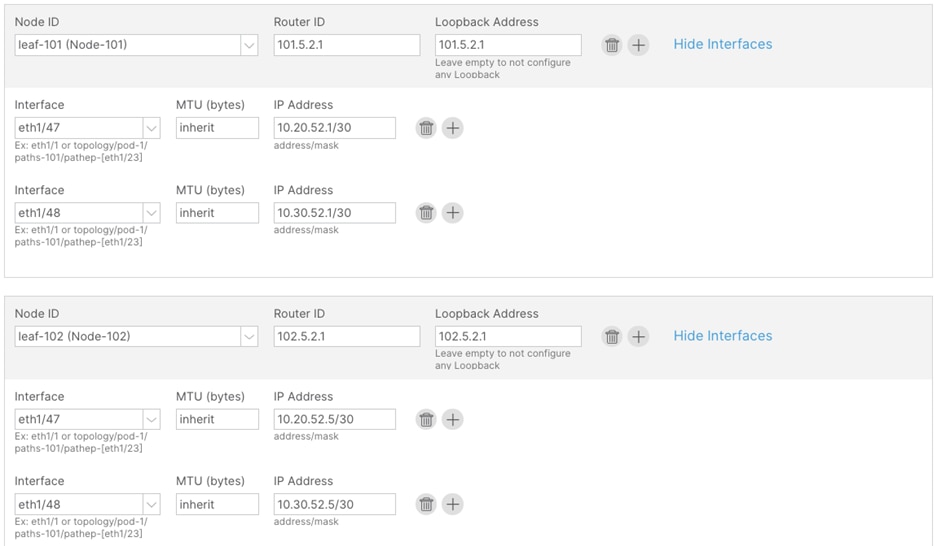
Step 4. In the Nodes and Interfaces window, perform the following actions:
a. In the Interface Types > Layer 3 section, select Sub-Interface.
b. In the Node drop-down list, select the first border leaf-node. (leaf-101)
c. In the Router ID field, enter the router ID. (101.5.2.1)
d. In the Interface drop-down list, select the interface connected to c8500-1. (1/47)
e. In the Encap Value, enter the VLAN for the connection to c8500-1 (2052)
f. In the IP Address field, enter the IP address. (10.20.52.1/30)
Step 5. Click the + sign to add a new interface
a. In the Interface drop-down list, select the interface connected to c8500-2. (1/48)
b. In the Encap Value, enter the VLAN for the connection to c8500-2. (3052)
c. In the IP Address field, enter the IP address. (10.30.52.1/30)
Step 6. In the Node field, click the + sign to add another node field.
Step 7. In the new Node field, perform the following actions:
a. In the Node drop-down list, select the second border leaf-node. (leaf-102)
b. In the Router ID field, enter the router ID. (102.5.2.1)
c. In the Interface drop-down list, select the interface connected to c8500-1. (1/47)
d. In the Encap Value, enter the VLAN for the connection to c8500-1 (2052)
e. In the IP Address field, enter the IP address. (10.20.52.5/30)
Step 8. Click the + sign to add a new interface.
a. In the Interface drop-down list, select the interface connected to c8500-2. (1/48)
b. In the Encap Value, enter the VLAN for the connection to c8500-2. (3052)
c. In the IP Address field, enter the IP address. (10.30.52.5/30)
Step 9. Confirm that all configuration has been provided and proceed to the next step of the wizard.
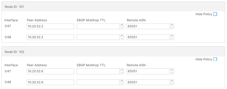
Step 10. In the Protocols window, perform the following actions:
a. In the Interface Policies field, enter the Peer Address and Remote ASN:
Node ID: 101 1/47, Peer Address (10.20.52.2) and the Remote ASN. (65051)
Node ID: 101 1/48, Peer Address (10.30.52.2) and the Remote ASN. (65051)
Node ID: 102 1/47, Peer Address (10.20.52.6) and the Remote ASN. (65051)
Node ID: 102 1/48, Peer Address (10.30.52.6) and the Remote ASN. (65051)
Step 11. In the External EPG window, perform the following actions:
a. In the Name field, enter a name for the external EPG (external-subnets)
b. Uncheck the Default EPG for all external networks checkbox.
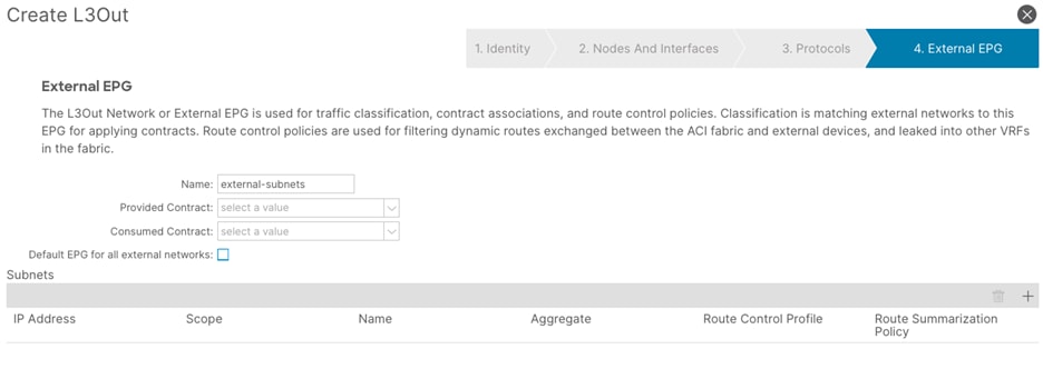
c. In the Subnets field, click the + sign to add a new subnet.
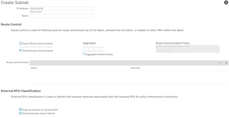
Step 12. In the Create Subnet window, perform the following actions:
a. In the IP Address field, enter the remote prefix. (10.52.0.0/16)
Note: The remote prefix represents an exact match on the VPC CIDR. For multiple VPCs, add additional remote prefixes.
b. Select Shared Route Control Subnet, External Subnets for External EPG, and Shared Security Import Subnet.
Provide Communication
The configuration steps thus far described how to set up the shared components needed for external connectivity to other VRFs within this tenant. As described in this chapter's introduction, this section will focus on contract creation. This example configuration will provide example naming and configuration, to allow both ICMP and TCP traffic. This can be customized as per user requirements.
Procedure 1. Create filters
Step 1. In the GUI Navigation pane, under Tenants (tenant-02), navigate to Contracts > Filters.
Step 2. Right-click and select Create Filter.
Step 3. In the Create Filter window, perform the following actions:
a. In the Name field, enter a name (icmp-src-any-to-dst-any)
b. In the Create Filter window, click the + button.
c. In the Entries field, perform the following actions:
i. In the Name field, enter a name (src-any-dst-any)
ii. In the Ethertype drop-down list, select IP.
iii. In the IP Protocol drop-down list, select ICMP.
Step 4. Submit the configuration and proceed with the next step.
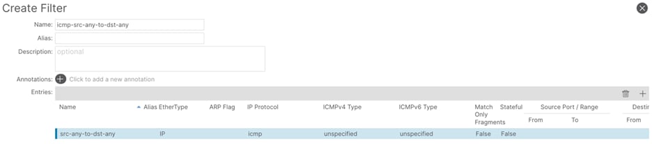
Step 5. In the Create Filter window, perform the following actions:
a. In the Name field, enter a name (tcp-src-any-to-dst-any)
b. In the Create Filter window, click the + button.
c. In the Entries field, perform the following actions:
i. In the Name field, enter a name (src-any-dst-any)
ii. In the Ethertype drop-down list, select IP.
iii. In the IP Protocol drop-down list, select TCP.
Step 6. Submit the configuration and proceed with the next step.
Procedure 2. Create contracts
Step 1. In the GUI Navigation pane, under Tenants (tenant-02), navigate to Contracts > Standard
Step 2. Right-click and select Create Contract.
Step 3. In the Name field, enter a name (permit-to-172.16.100_24)
Step 4. In the Scope field, select tenant.
Step 5. In the Create Contract window, click the + button to add a new subject.
Step 6. In the Create Contract Subject window, perform the following actions:
a. In the Name field, enter a name for the subject (other-entries)
b. In the Filters window, click the + button.
c. In the Filters Name drop-down list, select the filter (icmp-src-any-to-dst-any)
d. Click Update and proceed to the next step.
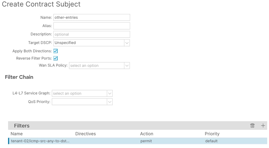
Step 7. In the Create Contract Subject window, perform the following actions:
a. In the Name field, enter a name for the second subject (tcp-entries)
b. In the Filters window, click the + button.
c. In the Filters Name drop-down list, select the filter (tcp-src-any-to-dst-any)
d. Click Update and proceed to the next step.
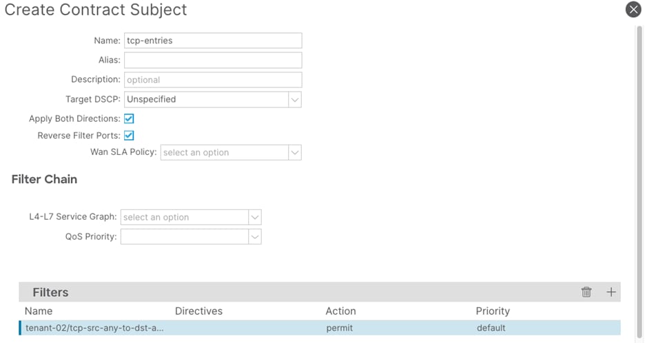
Step 8. In the Create Contract Subject window, confirm the configuration and click Submit.
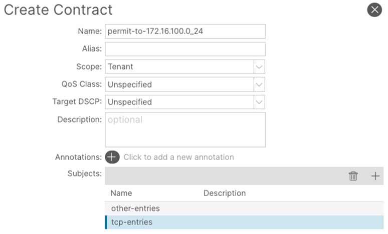
Procedure 3. Provide the contract
Step 1. In the GUI Navigation pane, under Tenants (tenant-02), navigate to Application Profiles > Application > network segments > 172.16.100.0_24.
Step 2. Right-click and select Add Provided Contract.
Step 3. In the Add Provided Contract window, select the contract created previously. (permit-to-172.16.100.0_24)
Note: To leak routes from vrf-02 to vrf-01, it is required to add the subnet under the provider side EPG, in EPG > Subnets. Ensure that the scope is set to Advertised Externally and Shared between VRFs. Below image illustrates the subnet configuration under the EPG.
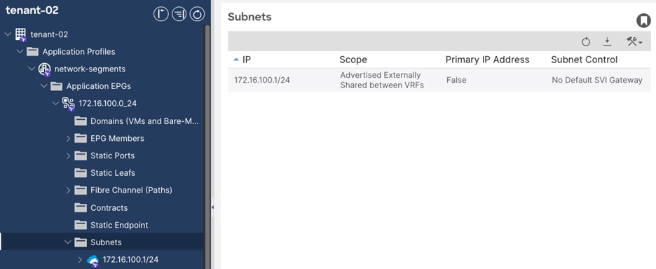
Procedure 4. Consume the contract
Step 1. In the GUI Navigation pane, under Tenants (tenant-02), navigate to Networking > L3Outs > tenant-02.vrf-01-bgp > External EPGs > external-subnets.
Step 2. In the External EPG window, navigate to Policy > Contracts.
Step 3. Click the Action button and select Add Consumed Contract.
Step 4. In the Add Consumed Contract window, select the previously created contracts (permit-to-172.16.100.0_24).
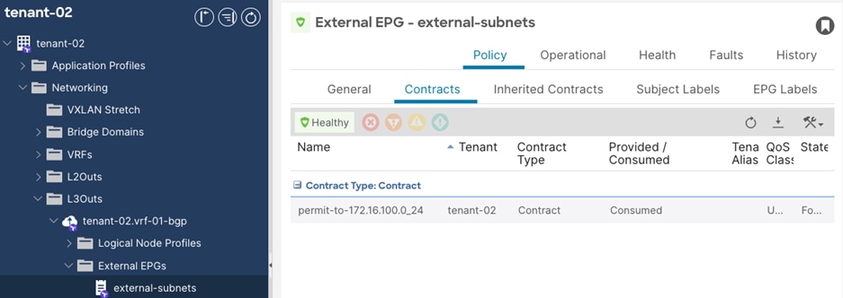
Shared-services Design for Multiple Tenants with Shared External Connectivity
A common requirement is the ability to provide shared services to workloads in the datacenter. Core services, such as DNS, DHCP, Active Directory, are typically provided centrally to different networks and tenants. Different tenants might also want to make use of a shared routed connection to the workloads in the public cloud, so that security and control is provided centrally, and can be consumed by other tenants.
In ACI terminology, this means sharing an L3Out instead of multiple L3Outs. This greatly reduces overhead and complexity.
Figure 30 shows the external connectivity that is used for this scenario.
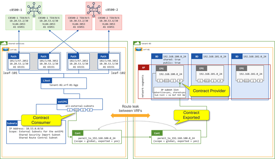
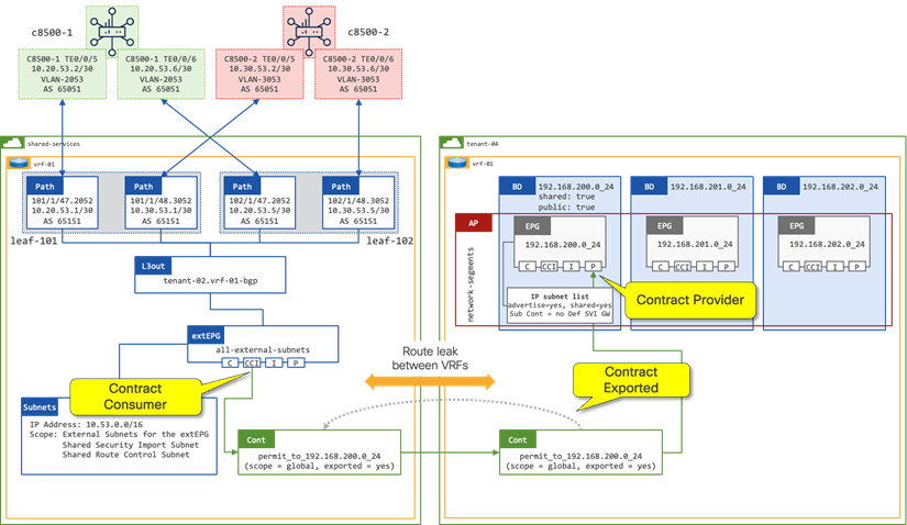
The scenarios make use of a common set of Fabric Access Policies. This access policy configuration is later used for the L3Out configuration under each tenant.
High-level steps
1. Create a VLAN pool for the VLAN used on the sub-interfaces connected to the SD-WAN routers. (shared-services.vrf-01-bgp)
2. Create a L3 Domain for the L3Out in the shared-services tenant. (shared-services.vrf-01-bgp)
3. Create a shared-services Tenant. (shared-services)
4. Create a VRF for the shared L3Out. (vrf-01)
5. Create a L3Out for the BGP adjacencies to the SD-WAN routers. (shared-services.vrf-01-bgp)
6. Create Filters to determine which type of traffic is allowed between the external and internal networks. Example filters are used. (icmp-src-any-to-dst-any and tcp-src-any-to-dst-any)
7. Create Contracts in the tenants that want to communicate with prefixes behind the SD-WAN domain. The subjects for these contracts will reference the previously created filters.
8. Provide the Contracts on the provider side EPGs.
9. Export the Contracts to the shared-services tenant.
10. Consume the contracts on the extEPG on the shared L3Out to allow for external communication to traverse to the provider side EPGs.
Procedure 1. Create a VLAN pool
Step 1. In the GUI Navigation pane, under Fabric, navigate to Access Policies > Pools > VLAN.
Step 2. Right-click and select Create VLAN Pool.
Step 3. In the Create VLAN Pool screen, perform the following actions:
a. In the Name field, enter the name for the VLAN pool. (shared-services.vrf-01-bgp)
b. Set the Allocation Mode to Static Allocation.
c. Click the + sign to add a new Encap Block.
d. In the Description field, optionally provide a description (vlan to c8500-1)
e. In the Range fields, provide the VLAN to be used for sub-interface connected to c8500-1. (2051)
f. Click the + sign to add a new Encap Block for the VLANs to be used for sub-interfaces connected to c8500-2.
g. In the Description field, optionally provide a description. (vlan to c8500-2)
h. In the Range fields, provide the VLAN range to be used for sub-interfaces connected to c8500-2. (3051)
Procedure 2. Create a L3 Domain
Step 1. In the GUI Navigation pane, under Fabric, navigate to Access Policies > Physical and External Domains > L3 Domains.
Step 2. Right-click and select Create L3 Domain.
Step 3. In the Name field, enter a name for the L3 Domain. (shared-services.vrf-01-bgp)
Step 4. In the VLAN Pool field, select the previously created VLAN Pool (shared-services.vrf-01-bgp)
Tenant Configuration
In previous scenarios, tenants were assumed. As discussed before, the objective of this scenario is to provide shared L3Out services to one or multiple different tenants (tenant-03 and tenant-04). Therefore, a new tenant will be created (shared-services).
Procedure 3. Create a tenant
Step 1. In the GUI Navigation pane, navigate to Tenants.
Step 2. In the GUI Navigation bar, click Add Tenant.
Step 3. In the Create Tenant window, perform the following actions:
a. In the Name field, enter the name. (shared-services)
b. Leave the rest of the settings default.
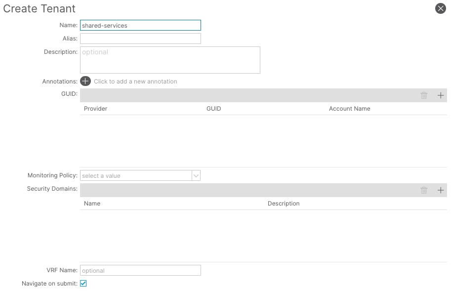
Procedure 4. Create a VRF for the L3Out
Step 1. In the GUI Navigation pane, under Tenants (shared-services), navigate to Networking > VRFs.
Step 2. Right-click and select Create VRF.
Step 3. In the Create VRF window, perform the following actions:
a. In the Name field, enter the name. (vrf-01)
b. Uncheck Create a Bridge Domain.
c. Leave the rest of the settings default.
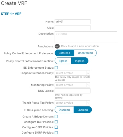
Procedure 5. Create a L3Out
Step 1. In the GUI Navigation pane, under Tenants (shared-services), navigate to Networking > L3Outs.
Step 2. Right-click and select Create L3Out.
Step 3. In the Create VRF wizard, perform the following actions:
a. In the Name field, enter the name. (shared-services.vrf-01-bgp)
b. In the VRF field, select the previously created VRF (vrf-01)
c. In the L3 Domain field, select the previously created L3 Domain (shared-services.vrf-01-bgp)
d. Select the BGP checkbox.
e. Proceed to the next step of the wizard by clicking Next.
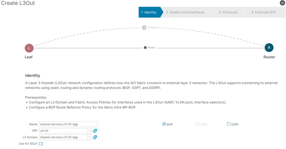
Step 4. In the Nodes and Interfaces window, perform the following actions:
a. In the Interface Types > Layer 3 section, select Sub-Interface.
b. In the Node drop-down list, select the first border leaf-node. (leaf-101)
c. In the Router ID field, enter the router ID. (101.5.3.1)
d. In the Interface drop-down list, select the interface connected to c8500-1. (1/47)
e. In the Encap Value, enter the VLAN for the connection to c8500-1 (2053)
f. In the IP Address field, enter the IP address. (10.20.53.1/30)
Step 5. Click the + sign to add a new interface.
a. In the Interface drop-down list, select the interface connected to c8500-2. (1/48)
b. In the Encap Value, enter the VLAN for the connection to c8500-2. (3053)
c. In the IP Address field, enter the IP address. (10.30.53.1/30)
Step 6. In the Node field, click the + sign to add another node field.
Step 7. In the new Node field, perform the following actions:
a. In the Node drop-down list, select the second border leaf-node. (leaf-102)
b. In the Router ID field, enter the router ID. (102.5.3.1)
c. In the Interface drop-down list, select the interface connected to c8500-1. (1/47)
d. In the Encap Value, enter the VLAN for the connection to c8500-1 (2053)
e. In the IP Address field, enter the IP address. (10.20.53.5/30)
Step 8. Click the + sign to add a new interface.
a. In the Interface drop-down list, select the interface connected to c8500-2. (1/48)
b. In the Encap Value, enter the VLAN for the connection to c8500-2. (3053)
c. In the IP Address field, enter the IP address. (10.30.53.5/30)
Step 9. Confirm that all configuration has been provided and proceed to the next step of the wizard.
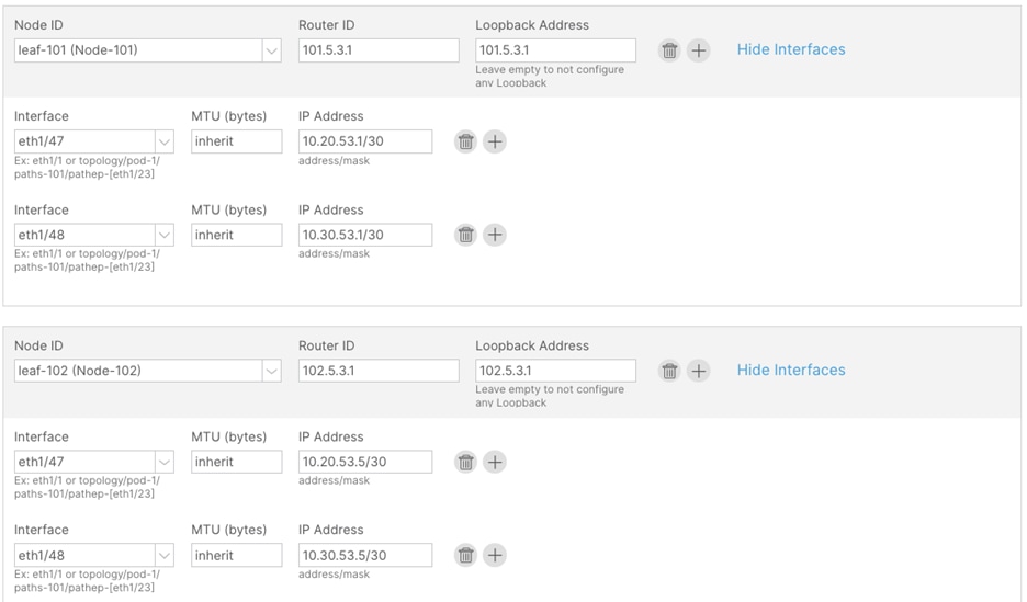
Step 10. In the Protocols window, perform the following actions:
a. In the Interface Policies field, enter the Peer Address and Remote ASN:
Node ID: 101 1/47, Peer Address (10.20.53.2) and the Remote ASN. (65051)
Node ID: 101 1/48, Peer Address (10.30.53.2) and the Remote ASN. (65051)
Node ID: 102 1/47, Peer Address (10.20.53.6) and the Remote ASN. (65051)
Node ID: 102 1/48, Peer Address (10.30.53.6) and the Remote ASN. (65051)
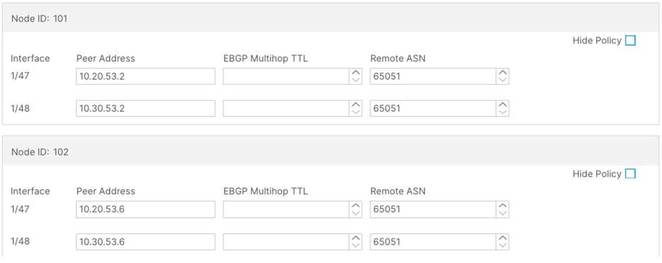
Step 11. In the External EPG window, perform the following actions:
a. In the Name field, enter a name for the external EPG (external-subnets)
b. Uncheck the Default EPG for all external networks checkbox.
c. In the Subnets field, click the + sign to add a new subnet.
d. In the Create Subnet window, perform the following actions:
e. In the IP Address field, enter the remote prefix. (10.53.0.0/16)
Note: The remote prefix represents an exact match on the VPC CIDR. For multiple VPCs, add additional remote prefixes.
Step 12. Select Shared Route Control Subnet, External Subnets for External EPG, and Shared Security Import Subnet.
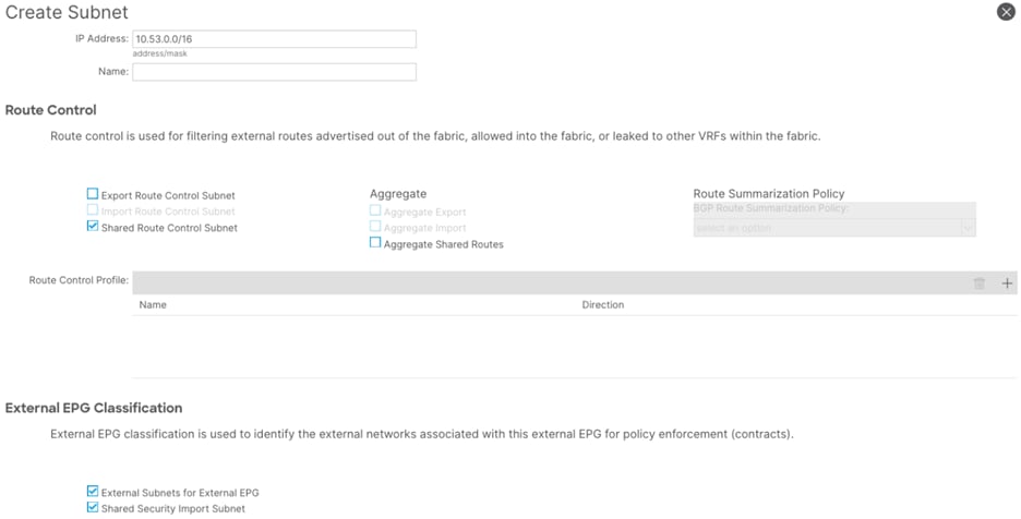
Provide Communication
The configuration steps thus far described how to set up the shared components needed for external connectivity. Other tenants can now leverage this L3Out by using contracts. The configuration guide will not provide the steps required to configure those tenants. It will solely focus on contract creation. In this configuration section, contracts, subjects, and their filters will be configured in two tenants (tenant-03 and tenant-04). This example configuration will provide example naming and configuration, to allow both ICMP and TCP traffic. This can be customized as per user requirements.
Procedure 6. Create filters
Step 1. In the GUI Navigation pane, under Tenants (tenant-03), navigate to Contracts > Filters.
Step 2. Right-click and select Create Filter.
Step 3. In the Create Filter window, perform the following actions:
a. In the Name field, enter a name (icmp-src-any-to-dst-any)
b. In the Create Filter window, click the + button.
c. In the Entries field, perform the following actions:
i. In the Name field, enter a name (src-any-dst-any)
ii. In the Ethertype drop-down list, select IP.
iii. In the IP Protocol drop-down list, select ICMP.
iv. Submit the configuration and proceed with the next step.

Step 4. In the Create Filter window, perform the following actions:
a. In the Name field, enter a name (tcp-src-any-to-dst-any)
b. In the Create Filter window, click the + button.
c. In the Entries field, perform the following actions:
i. In the Name field, enter a name (src-any-dst-any)
ii. In the Ethertype drop-down list, select IP.
iii. In the IP Protocol drop-down list, select TCP.
Step 5. Submit the configuration and proceed with the next step.

Procedure 7. Create contracts
Step 1. In the GUI Navigation pane, under Tenants (tenant-03), navigate to Contracts > Standard.
Step 2. Right-click and select Create Contract.
Step 3. In the Name field, enter a name (permit-to-192.168.100.0_24)
Step 4. In the Scope field, select global.
Step 5. In the Create Contract window, click the + button to add a new subject.
Step 6. In the Create Contract Subject window, perform the following actions:
a. In the Name field, enter a name for the subject (other-entries)
b. In the Filters window, click the + button.
c. In the Filters Name drop-down list, select the filter (icmp-src-any-to-dst-any)
d. Click Update and proceed to the next step.

Step 7. In the Create Contract Subject window, perform the following actions:
a. In the Name field, enter a name for the second subject (tcp-entries)
b. In the Filters window, click the + button.
c. In the Filters Name drop-down list, select the filter (tcp-src-any-to-dst-any)
d. Click Update and proceed to the next step.
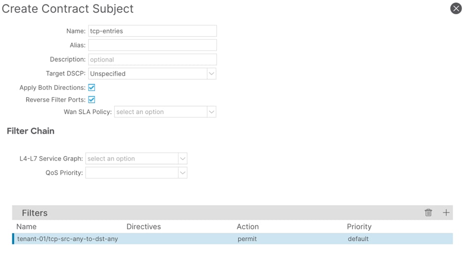
Step 8. In the Create Contract Subject window, confirm the configuration and click Submit.
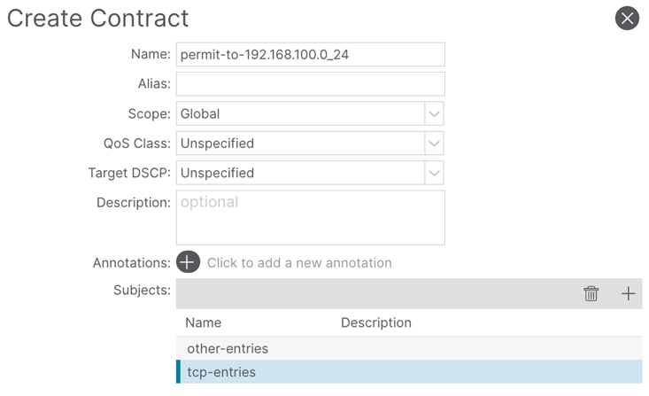
Step 9. Repeat these steps for tenant-04. The exception is the name of the contract. This should reflect the BD subnet used in tenant-04. (permit-to-192.168.200.0_24)
Note: In the provided example, tenant-04 contains different bridge domain subnets. This is because networks from both tenant-03 and tenant-04 are leaked into the shared-services tenant (vrf-01). Therefore, uniqueness is ensured to avoid IP overlap.
Procedure 8. Provide the contract
Step 1. In the GUI Navigation pane, under Tenants (tenant-03), navigate to Application Profiles > Application > network segments > 192.168.100.0_24.
Step 2. Right-click and select Add Provided Contract.
Step 3. In the Add Provided Contract window, select the contract created previously. (permit-to-192.168.100.0_24)
Step 4. Repeat these steps for the configuration in tenant-04. This should reflect the BD subnet used in tenant-04. (permit-to-192.168.200.0_24)
Procedure 9. Export the contract
Step 1. In the GUI Navigation pane, under Tenants (tenant-03), navigate to Contracts > Standard.
Step 2. Right-click the previously created contract and select Export Contract.
Step 3. In the Export Contract window, perform the following actions:
a. In the Name field, enter the name to uniquely identify this contract in the shared-services tenant. (permit-to-192.168.100.0-24)
b. In the Tenant drop-down list, select the shared-services tenant (shared-services)
Step 4. Repeat thee steps in tenant-04 for EPG 192.168.200.0_24.
Note: In order route leak to the shared services tenant (vrf-01), as described in the route-leaking chapter. It is required to add the subnet that should be leaked under EPG > Subnets. Ensure that the scope is set to Advertised Externally and Shared between VRFs. These scope options also need to match the bridge domain subnet scope.
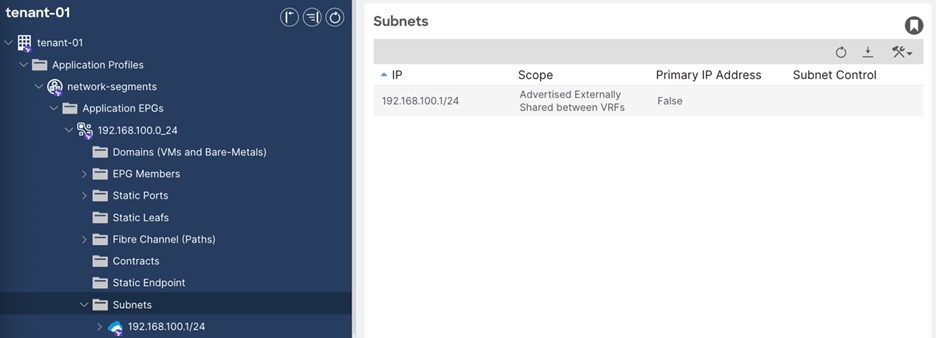
Procedure 10. Consume the contract
Step 1. In the GUI Navigation pane, under Tenants (shared-services), navigate to Contracts > Imported.
Step 2. Ensure that the exported contracts are created.
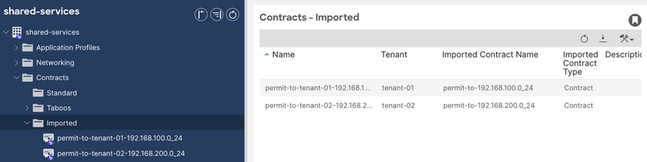
Step 3. In the shared-services tenant, navigate to Networking > L3Outs > shared-services.vrf-01-bgp > External EPGs > external-subnets.
Step 4. In the External EPG window, navigate to Policy > Contracts.
Step 5. Click the Action button and click Add Consumed Contract Interface.
Step 6. In the Add Consumed Contract Interface window, select the previously exported contracts (permit-to-tenant-03-192.168.100.0_24). Repeat this step for any other contracts (permit-to-tenant-04-192.168.200.0_24)
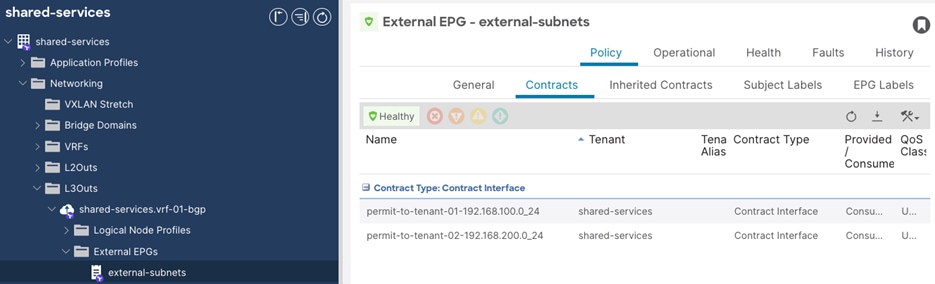
SD-WAN Configuration Overview
This section of the SD-WAN configuration explains:
● The connectivity from WAN Edges (Catalyst 8500) to ACI
● Create feature template, device template and attach to Catalyst 8500
● Deploy Cloud Gateway (Catalyst 8000V) in AWS
● Connect host VPCs and map SD-WAN VPNs to host VPCs
Table 1 lists the mapping from ACI tenants to SD-WAN VPNs to host VPCs.
Table 1. ACI tenant mapping to SD-WAN VPNs to host VPCs
| Tenants |
SD-WAN VPNs |
Host VPCs |
| Tenant-01 |
VPN 51 |
aci-aws-tenant-01 |
| Tenant-02 |
VPN 52 |
aci-aws-tenant-02 |
| Shared-services |
VPN 53 |
aci-aws-shared |
Configure WAN Edge Connected to ACI
In the documented setup, two Catalyst 8500 routers are in the controller mode, reachable from SD-WAN Manager, and are attached to a device configuration template. The Catalyst 8500 routers are directly connected with ACI border leaf on interfaces TenGigabitEthernet0/0/5 and TenGigabitEthernet0/0/6 as shown Figure 31.
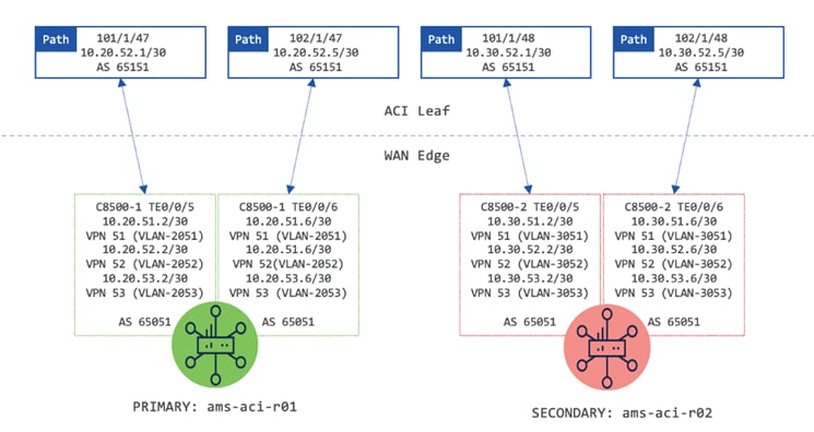
Note: This design guide is based on Catalyst 8500 configurated using Device and Feature Templates (also known as UX 1.0 configuration). Nevertheless, the same results can be achieved with Configuration Groups (UX 2.0 configuration).
To achieve a mutual redistribution of SD-WAN and ACI networks, as well as maintain segmentation, there are three sub-interfaces needed on each physically connected interface. Each sub-interface must belong to a different VPN. Configured VPNs must have BGP enabled. The redistribution from BGP to OMP must be allowed.
The software-defined network allows preparing a configuration framework (template), which later can be used and customized with variables’ values (such as IPs, names, and so on). To ensure information exchange between SD-WAN and ACI fabrics, the administrator must:
1. Create dedicated device and feature templates for the Catalyst 8500 (WAN Edge).
2. Attach device template to WAN Edges.
See Attachments for the complete SD-WAN configurations including VRF, interfaces, BGP, Tunnels, OMP and IPsec.
Procedure 1. Create Dedicated Feature Templates for Catalyst 8500 Routers
Catalyst SD-WAN supports splitting the process of preparing configuration templates and applying it to devices. It eliminates waterfalling changes immediately to a production network. This section describes the steps needed to generate a configuration template. The configuration is applied to the devices in a later stage.
Note: In Catalyst SD-WAN templates, for each parameter that has a default value, the scope is set to Default (indicated by a check mark), and the default setting or value is shown. To change the default or to enter a value, select the drop-down list of the parameter field and select: Device Specific or Global.
For device-specific parameters, an administrator cannot enter a value in the template. The value is provided when the template is attached to a device. Contrary, global parameters must have a value entered in the template.
Note: The physical connectivity between ACI leaf and WAN Edge must be considered while creating the templates.
Step 1. In the Cisco SD-WAN Manager menu, navigate to Configuration > Templates. In the Configuration window, select the Feature Templates tab.
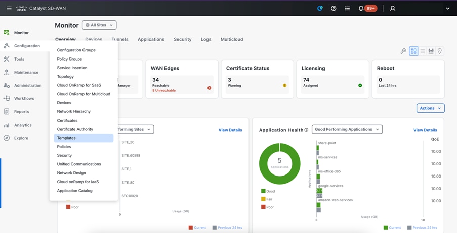
Step 2. In the Add Template window, select the applicable platform (C8500-12X4QC), followed by selecting Cisco VPN from the VPN section. In the Cisco VPN window, perform the following actions:
a. In the Cisco VPN window, provide a Template Name (aci_serv_vpn51).
b. Provide a description. (Isolated VPN for ACI-SDWAN connection to tenant-01).
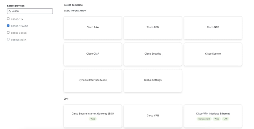
c. In the Basic Configuration section, enter a VPN number (51).
d. Expand the scope option for Name, select Global and provide a name (tenant-01).
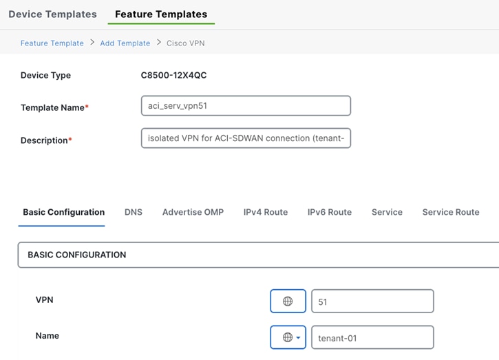
e. Click Save to save the feature template.
Step 3. Repeat Step 2 to create feature templates for VPN 52 and 53. Table 2 lists the feature templates for each service VPN.
| Template name |
Description |
VPN |
| aci_serv_vpn51 |
isolated VPN for ACI-SDWAN connection (tenant-01) |
51 |
| aci_serv_vpn52 |
isolated VPN for ACI-SDWAN connection (tenant-02) |
52 |
| aci_serv_vpn53 |
isolated VPN for ACI-SDWAN connection (shared-services) |
53 |
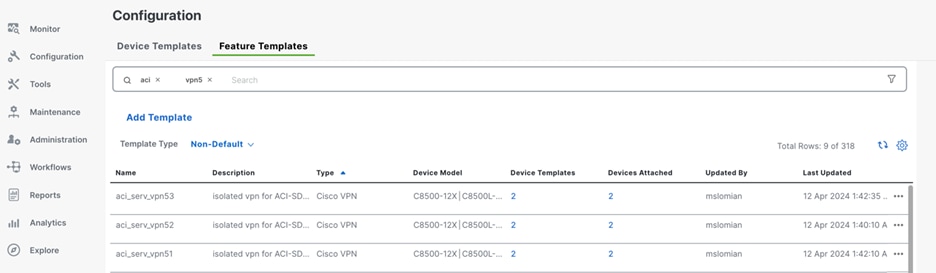
Step 4. In the Cisco SD-WAN Manager menu, navigate to Configuration > Templates. In the Configuration window, select the Feature Templates tab.
Step 5. Change Template Type view to Default and search for Factory_Default_Cisco_OMP_ipv46_Template.
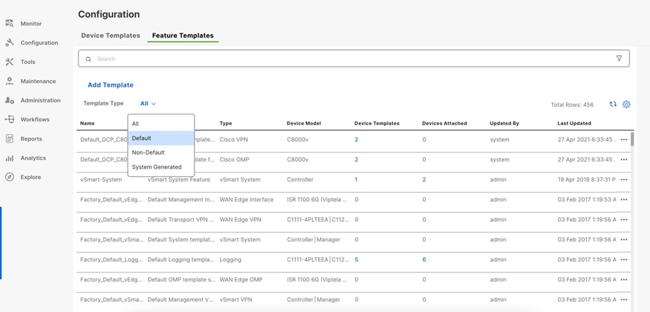
Step 6. On the right side of the Feature Templates window, click the ellipses in the row for Factory_Default_Cisco_OMP_ipv46_Template and select Copy.
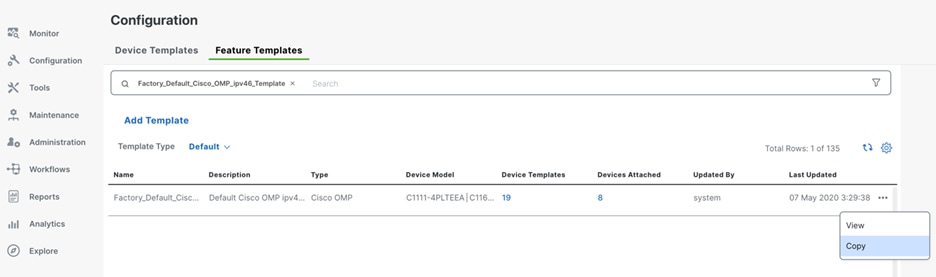
Step 7. In the Template Copy window, provide a Template Name (ACI_Cisco_OMP_ipv46) and select Copy.
Step 8. Back in the Feature Template window, click Add Template.
Step 9. In the Add Template window, select the applicable platform (C8500-12X4QC), followed by selecting Cisco VPN Interface Ethernet from the VPN section. In the Cisco VPN Ethernet window, perform the following actions:
a. Provide a Template Name (aci_serv_vpn51_int01).
b. Provide a Description (aci_serv_vpn51_int01).
c. In the Basic Configuration section, navigate to the Shutdown parameter and change the scope to Global and select No.
d. Expand the scope option for Interface Name, select Device Specific and provide a Key (serv_vpn51_int1_name).
e. Expand the scope option for IPv4 Address/ prefix-length, select Device Specific and provide a Key (vpn51_int_ip_address).
f. Click Save to save the feature template.
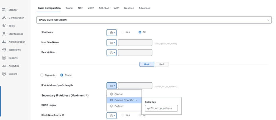
Step 10. Repeat steps 8-9 for the other templates. In total, 6 templates should be created.
| Template name |
Shutdown |
Interface name |
IPv4 Address/ prefix length |
| aci_serv_vpn51_int01 |
No |
serv_vpn51_int1_name |
vpn51_int1_ip_address |
| aci_serv_vpn51_int02 |
No |
serv_vpn51_int2_name |
vpn51_int2_ip_address |
| aci_serv_vpn52_int01 |
No |
serv_vpn52_int1_name |
vpn52_int1_ip_address |
| aci_serv_vpn52_int02 |
No |
serv_vpn52_int2_name |
vpn52_int2_ip_address |
| aci_serv_vpn53_int01 |
No |
serv_vpn53_int1_name |
vpn53_int1_ip_address |
| aci_serv_vpn53_int02 |
No |
serv_vpn53_int2_name |
vpn53_int2_ip_address |
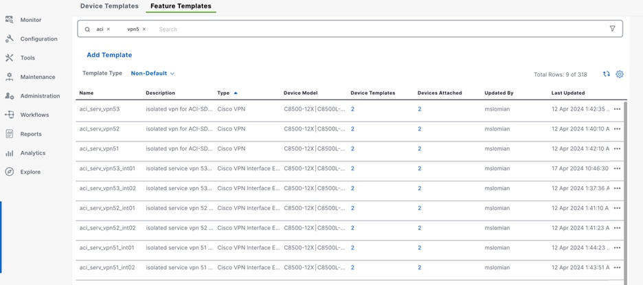
Step 11. From the Feature Template window, select Add Template.
Step 12. In the Add Template window, select the applicable platform (C8500-12X4QC), followed by selecting Cisco BGP from the Other Templates section. In the Cisco BGP window, perform the following actions:
a. Provide a Template Name (AMS_C8500_bgp_aci).
b. Provide a Description (aci_serv_vpn51_int01).
c. In the Basic Configuration section, navigate to the Shutdown parameter and change the scope to Global and click No.
d. Expand the scope option for Interface Name, select Device Specific and provide a Key (serv_vpn51_int1_name).
e. Expand the scope option for IPv4 Address/ prefix-length, select Device Specific and provide a Key (vpn51_int_ip_address).
f. Click Save to save the feature template.
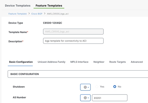
g. In the Unicast Address Family section, select New Redistribute.
h. In the Protocol field, select OMP and click Add.
Step 13. Repeat the previous step (in the Unicast Address Family section, select New Redistribute) for Connected.
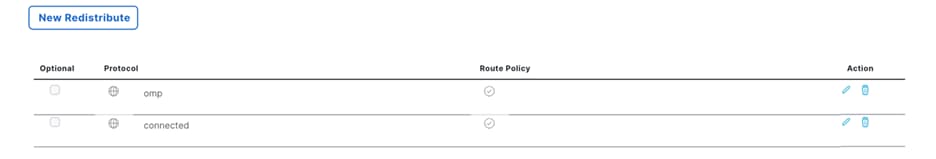
Step 14. In the Cisco BGP template window, navigate to the Neighbor tab.
Step 15. Select New Neighbor.
Step 16. In the New Neighbor section, navigate to the Address field and change the scope to Device Specific and provide a Key (bgp_neighbor1_address).
Step 17. In the Description field, change the scope to Device Specific and provide a Key (bgp_neighbor1_description).
Step 18. Navigate to the Remote AS field and change the scope to Global and provide a value (65151).
Step 19. Click Add to add the New Neighbor configuration.
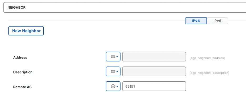
Step 20. Each router is connected to two ACI leaf switches. Each router will therefore have two BGP neighbors for each AS. Repeat these steps to add another New Neighbor.
Step 21. Click Save to save the Cisco BGP template.
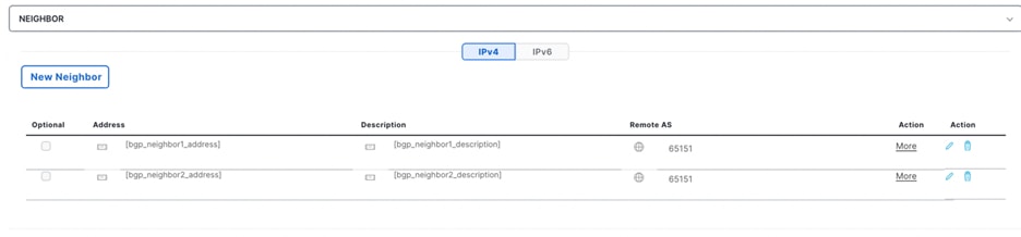
Step 22. In the Cisco SD-WAN Manager menu, navigate to Configuration > Templates. In the Device Templates window, select Create Template followed by From Feature Template.
Step 23. In the Device Templates window, perform the following actions:
a. In the Device Model menu, select the applicable platform (C8500-12X4QC).
b. In the Device Role menu, select SDWAN Edge.
c. In the Template Name field, provide a name (AMS_C8500_r01).
d. In the Description field, provide a description (AMS_C8500_r01).
e. Navigate to the Basic Information section and in the Cisco OMP menu, select the previously created OMP template (ACI_Cisco_OMP_ipv46).
Step 24. Navigate to the Service VPN section and select Add VPN.
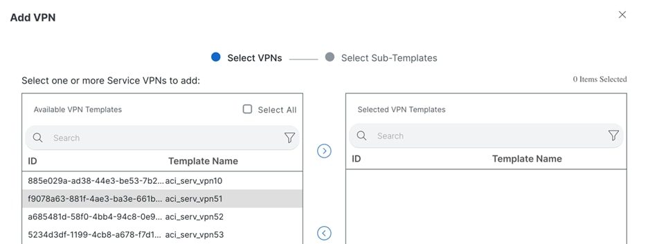
Step 25. Select aci_serv_vpn51 and use the arrow to move the template to the column on the right and click Next.
Step 26. In the Add VPN window, click the + symbol to add a Cisco BGP template.
Step 27. In the Cisco BGP menu, select the previously created BGP template (AMS_C8500_bgp_aci).
Step 28. Click the + symbol to add two instances of Cisco VPN Interface Ethernet.
Step 29. In the Cisco VPN Interface Ethernet menus, select the previously created interface templates (aci_serv_vpn51_int01 and aci_serv_vpn51_int02).
Step 30. Click Add.
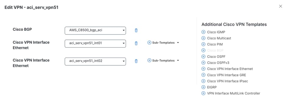
Step 31. Repeat these steps for aci_serv_vpn52 and aci_serv_vpn53. Make sure to select the correct Cisco VPN Interface Ethernet template for each VPN.
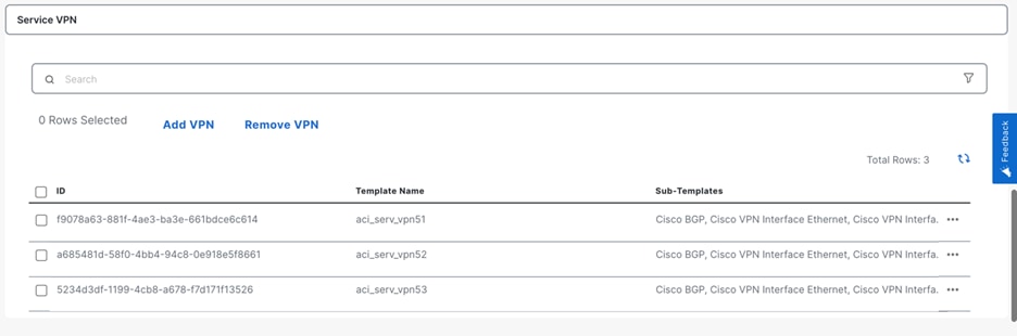
Step 32. Verify the configuration and select Create.
Step 33. Repeat steps 10-11 to create a device template for the second router (AMS_C8500_r02).
Procedure 2. Attach Dedicated Device Template for Catalyst 8500 Routers
The previous procedure explained how to configure device templates. This section explains how to associate the device templates to the devices, and which parameters to use.
Step 1. In the Cisco SD-WAN Manager menu, navigate to Configuration > Templates.
Step 2. In the Device Template window, use the search field to find the device template created previously (AMS-C8500-r01). Once located, select the three dots menu on the right side of the window, and select Attach devices.
Step 3. In the popup, find chassis number that are physically connected to ACI leaves (leaf-101 and leaf 102). Select the router that will act as primary router and click arrow to move it to the right column and click Attach.
Step 4. Fill in the variables for the device by referring to Table 4.
Table 4. Input for primary WAN Edge (AMS_C8500_r01)
| System IP |
4.4.4.4 |
| Hostname |
ams-aci-r02 |
| Interface Name(serv_vpn53_int2_name) |
TenGigabitEthernet0/0/6.3053 |
| IPv4 Address/ prefix-length(vpn53_int2_ip_address) |
10.30.53.6/30 |
| Interface Name(serv_vpn53_if_name) |
TenGigabitEthernet0/0/5.3053 |
| IPv4 Address/ prefix-length(vpn53_if_ip_address) |
10.30.53.2/30 |
| Address(bgp_neighbor1_address) |
10.30.53.5 |
| Address(bgp_neighbor2_address) |
10.30.53.1 |
| Description(bgp_neighbor1_description) |
shared-services |
| Description(bgp_neighbor2_description) |
shared-services |
| Interface Name(serv_vpn52_int2_name) |
TenGigabitEthernet0/0/5.3052 |
| IPv4 Address/ prefix-length(vpn52_int2_ip_address) |
10.30.52.230 |
| Interface Name(serv_vpn52_int1_name) |
TenGigabitEthernet0/0/6.3052 |
| IPv4 Address/ prefix-length(vpn52_int1_ip_address) |
10.30.52.6/30 |
| Address(bgp_neighbor1_address) |
10.30.52.5 |
| Address(bgp_neighbor2_address) |
10.30.52.1 |
| Description(bgp_neighbor1_description) |
Tenant-02 |
| Description(bgp_neighbor2_description) |
Tenant-02 |
| Interface Name(serv_vpn51_int2_name) |
TenGigabitEthernet0/0/5.3051 |
| IPv4 Address/ prefix-length(vpn51_int2_ip_address) |
10.30.51.2/30 |
| Interface Name(serv_vpn51_int1_name) |
TenGigabitEthernet0/0/6.2051 |
| IPv4 Address/ prefix-length(vpn51_int1_ip_address) |
10.30.51.6/30 |
| Address(bgp_neighbor1_address) |
10.30.51.1 |
| Address(bgp_neighbor2_address) |
10.30.51.5 |
| Description(bgp_neighbor1_description) |
Tenant-01 |
| Description(bgp_neighbor2_description) |
Tenant-01 |
| Site ID |
4444 |
Deploy Catalyst 8000V in AWS
Administrators configure and manage Cloud OnRamp for Multicloud environments through the graphical interface - Cisco SD-WAN Manager. A configuration wizard in Cisco SD-WAN Manager automates the bring-up of the cloud gateways and the connections between public-cloud applications and the users of those applications at DC via the overlay network. This feature works with AWS VPC on Cisco cloud routers.
Note: As of Cisco IOS XE SD-WAN Release 17.13.1 and Cisco Catalyst SD-WAN Release 20.13.1, it is supported to deploy cloud gateways using one of 5 AWS solutions: Transit Gateway VPN-based, Connect-based, Branch Connect, Cloud WAN VPN-based, Cloud WAN Connect-based. This design guide focuses on AWS Cloud WAN – Connect based. Cisco is committed to ensure a consistent experience regardless of a cloud provider and gateway deployment, however, minor differences may be seen.
High-level Steps
1. Associate a cloud account with SD-WAN Manager.
2. Configure cloud global settings in SD-WAN Manager.
3. Associate virtual devices with templates.
4. Prepare virtual routers values and create cloud gateway.
Procedure 1. Associate Cloud Account
Step 1. In the Cisco SD-WAN Manager menu, navigate to Configuration > Cloud OnRamp for Multicloud.
Step 2. Navigate to the bottom of this page and select Associate Cloud Account from the Setup pane.
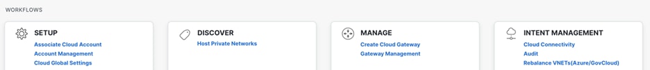
Step 3. In the Cloud Provider field, select Amazon Web Services from the drop-down list.
Step 4. In the Account Name field, provide a name for the cloud account.
Step 5. (Optionally, provide a description in the Description field.
Step 6. In the Use for Cloud Gateway field, select Yes.
Note: As of Cisco Catalyst SD-WAN Release 20.13.1, only one account can be used to deploy cloud gateways connected to AWS Cloud WAN. To onboard additional cloud accounts, administrators can select “No” to deploy the cloud gateway, when adding a cloud account. This allows additional accounts to be connected. The other accounts will leverage a common cloud gateway.
Step 7. In the Login in to AWS with field, select the preferred method Key or IAM role.
Note: If the Cisco Catalyst SD-WAN Manager is hosted by Cisco CloudOps on AWS, please read “Appendix F: Creating an AWS IAM Role” here: https://www.cisco.com/c/en/us/td/docs/solutions/CVD/SDWAN/Cisco_Cloud_onRamp_for_IaaS_AWS_Version2.html#AppendixFCreatinganAWSIAMRole
Step 8. Select Add.
Note: IAM Role as the authentication model is not available for controllers deployed on premise.
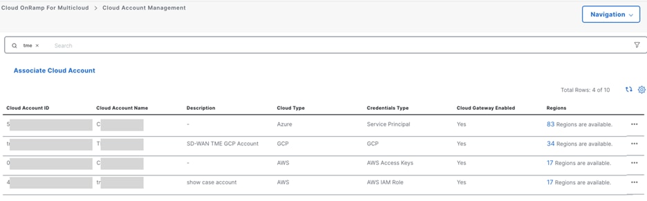
Procedure 2. Set Cloud Global Settings
Cloud Global Settings contain values such as default software for Cisco C8000V virtual routers, AWS Instance Types and cloud audit settings of the connectivity in the cloud.
Note: SD-WAN Manager Cloud OnRamp supports five AWS cloud solution (Cloud Gateway Solutions). This design guide makes use of Cloud Wan – Connect based, as this is the newest integration between Catalyst SD-WAN and AWS WAN solution, and it supports Tunnel-less connectivity. Read more about available options here: https://www.cisco.com/c/en/us/td/docs/routers/sdwan/configuration/cloudonramp/ios-xe-17/cloud-onramp-book-xe/cloud-onramp-multi-cloud-aws.html
Step 1. In the Cisco SD-WAN Manager menu, navigate to Configuration > Cloud OnRamp for Multicloud.
Step 2. Navigate to the bottom of this page and select Cloud Global Settings from the Setup pane.
Tech tip: Cloud global settings are reference values that are used for cloud gateway deployments (CGW) when a user needs to apply common settings to all CGWs. Each value can be adjusted individually during the deployment.
Step 3. In the Cloud Global Settings – view window, perform the following actions:
a. In the Cloud Provider menu, select Amazon Web Services .
b. In the Cloud Gateway Solution menu, select Cloud Wan – Connect based (using TVPC).
c. In the Reference Account Name, select the AWS account that was previously added.
d. In the Reference Region, select the AWS Region (us-west-2).
e. In the Software Image field, select a licensing option and select a recommended C8000V image.
Note: The choice of software image should be made by the network administrator considering Cisco recommendations and the network’s requirements. Cisco recommendations are shared here: https://software.cisco.com/download/home/286327102/type/282046477/release/Dublin-17.12.3a
Keep in mind that software release on routers must not be higher than on SD-WAN controllers. Check the combability matrix for more details: https://www.cisco.com/c/en/us/td/docs/routers/sdwan/release/notes/compatibility-and-server-recommendations.html
f. In the Instance Size menu, select c6in.large (2vCPU).
Note: The choice of Instance Size is dependent on the network’s requirements. Read more about supported instances: https://www.cisco.com/c/en/us/td/docs/routers/C8000V/AWS/deploying-c8000v-on-amazon-web-services/deploy-c8000v-on-amazon-web-services.html#notes-and-guidelines
g. In the IP Subnet Pool field, provide a subnet pool between /16 and /24. (10.72.0.0/16)
h. In the Cloud Gateway BGP ASN Offset, provide an AS number (64540).
i. In the Tunnel Count field, provide a number (1).
j. In the Intra Tag Communication, optionally select enabled.
k. In the Program Default Route in VPCs towards TGW/Core Network, optionally select enabled.
l. In the Full Mesh of Transit VPCs, select enabled.
m. In the Site-to-Site Tunnel Encapsulation Type menu, select GRE.
n. In the Enable Periodic Audit field, optionally select Enabled.
o. In the Enable Auto Correct field, optionally select Enabled.
p. Click Save to finish setting the cloud global settings.
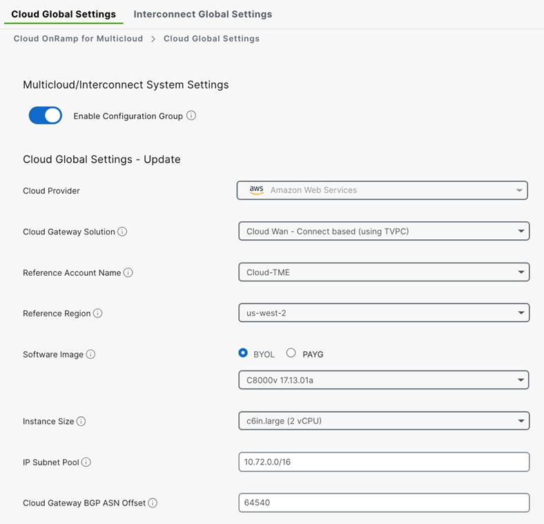
Create Cloud Gateway
Cloud Gateway (CGW) refers to virtual router instances deployed by Cloud OnRamp automation. This design guide focuses on AWS Cloud WAN where CGW is created with a pair of Catalyst 8000V routers, BGP sessions, cloud network edge (CNE - TGW under the hood in Cloud WAN).
Note: A prerequisite of this section is adding virtual devices to SD-WAN Manager. Follow the onboarding guide here: https://www.cisco.com/c/dam/en/us/td/docs/solutions/CVD/SDWAN/sdwan-wan-edge-onboarding-deploy-guide-2020nov.pdf
The process of CGW creation can be divided into three parts: connecting Smart Account with Manager, preparing virtual routers configuration, and deploying virtual instances for cloud gateway.
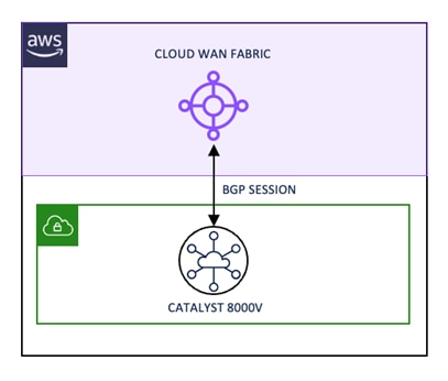
Connect Smart Account with Manager
Cisco Catalyst 8000V supports both Cisco IOS XE and the Cisco IOS XE SD-WAN functionalities through the autonomous mode and the controller mode, respectively. The controller mode delivers comprehensive SD-WAN, WAN gateway, and network services functions in the virtual and cloud environments.
For this design guide, two Catalyst 8000V are used. Refer to the Cisco SD-WAN Onboarding Guide for details on onboarding, licensing, and connecting Smart Account with SD-WAN Manager. When the virtual devices are visible in the user interface, proceed to the next section.
Note: Cisco SD-WAN Onboarding Guide: https://www.cisco.com/c/en/us/solutions/collateral/enterprise-networks/sd-wan/guide-c07-742221.html
Procedure 3. Prepare Catalyst 8000V Configuration
Step 1. In the Cisco SD-WAN Manager menu, navigate to Configuration > Devices > Wan Edges.
Step 2. On the Devices page make a note of two Chassis Numbers of C8000V that are currently not in use. Mind that you can differentiate physical routers from virtual ones based on their chassis number: virtual routers’ start with C8K-.
Step 3. In the Cisco SD-WAN Manager menu, navigate to Configuration > Templates.
Step 4. Change the Template Type view to Default, and search for Default_AWS_TGW_C8000V_Template_V01.
Step 5. Once located, select the three dots menu on the right side of the template and select Copy.
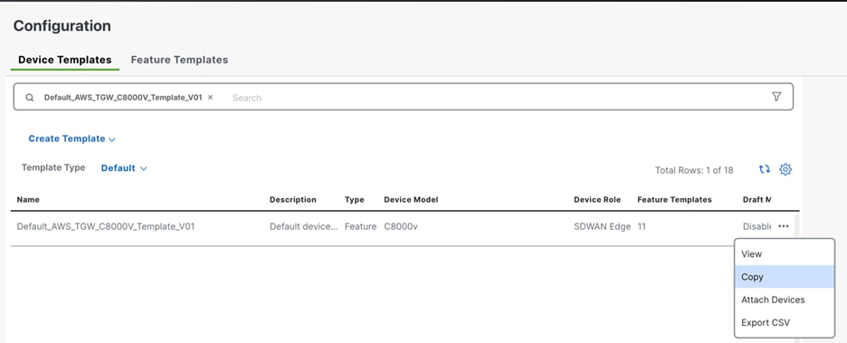
Step 6. In the Template Copy window, provide a name (AWS_cloud_wan_c8000v), followed by selecting Copy.
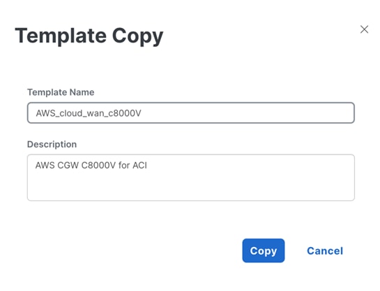
Step 7. In the Cisco SD-WAN Manager menu, navigate to Configuration > Templates and select the Feature Templates tab.
Step 8. In the Feature Templates windows, change the view filter to default and search for Default_VPN_1_Cisco_V01
Step 9. Once located, select the three dots menu on the right side of the template and select Copy.
Step 10. In the Template Name field, provide a name (AWS_service_vpn_1) followed by selecting Copy.
Step 11. In the Cisco SD-WAN Manager menu, navigate to Configuration > Templates.
Step 12. In the Device Templates window, Change the view filter to Non-Default to find and select the template that was created during step 5.
Step 13. Once located, select the three dots menu on the right side of the template and select Edit.
Step 14. In the Device Template Configuration window, navigate to the Service VPN section and select Add VPN.
Step 15. In the Add VPN window, select AWS_service_vpn_1, and use the arrow to move the template to the column on the right, followed by selecting Next.
Step 16. Proceed by selecting Add.
Step 17. Save the changes to the template by selecting Update.
Note: For cloud gateways deployed with Cloud OnRamp automation, VPN sub-templates for interfaces and BGP feature templates are required. These templates are generated automatically during the deployment process.
Step 18. In the Device Template window, use the search field to find the device template created previously in step 5 (AWS_cloud_wan_c8000V). Once located, select the three dots menu on the right side of the window, and select Attach devices.
Step 19. In the Attach Device window, find the device IDs from Step 2. Select them and use the arrow to move it to the right column and select Attach.
Step 20. Provide the variables for both devices. Hostnames (aws-west-aci-r01, aws-west-aci-r02), system IP (31.62.1.1, 31.62.1.2), site ID (3162).
Note: Devices under one cloud gateway must use the same site ID to achieve high availability set-up. In such case, routers are deployed in different AWS availability-zones but are treated as one branch in SD-WAN.
Step 21. Select Update and then Next to proceed.
Step 22. Check the config against any typos and click Configure Devices. In the popup accept deploying changes on both devices.
Step 23. After a few minutes you should see that changes are Scheduled because devices are currently offline.
Procedure 4. Deploy Catalyst 8000V Configuration
Step 1. From the Cisco SD-WAN Manager menu, click Configuration > Cloud OnRamp for Multicloud. Navigate to the bottom of the menu and select Create Cloud Gateway.
Step 2. In the Manage Cloud Gateway – Create window, select Amazon Web Services.
Step 3. Optionally, provide a description.
Step 4. In the Account Name drop-down list, select the appropriate cloud account.
Step 5. In the Region drop-down list, select the appropriate region.
Step 6. The instance Settings should be prepopulated with the settings provided in the Set Cloud Global Settings step. Verify the input provided and proceed to the next step.
Step 7. In the MRF role field, select the border option. Note that the border role selection is irrelevant in this design.
Step 8. Select Configure Device Parameters to finalize the deployment.
Note: CGW deployment may take up to 45 minutes depending on the AWS region and other settings when using Cloud WAN in 20.14.1 software release. Times may differ depending on the cloud network solution (TGW or Cloud WAN) and cloud service provider.
Be aware that the first deployment in a new region may fail due to AWS validations. While normally the AWS validation is resolved within minutes, it may take up to 4 hours for this process to complete. If the issue persists, AWS recommends opening a support case directly with AWS support.
Procedure 5. Connect Workloads
It is a common practice in enterprises to use separate cloud accounts for networking, security, and development purposes. Cisco Catalyst SD-WAN supports the discovery of cloud resources from multiple accounts if they are provisioned on Catalyst SD-WAN Manager. The process of connecting cloud resources with the network in Cloud WAN is done with tags (tag attachments – see the figure below) that a user can create in Manager and associate with VPC(s) to later use in a connectivity mapping table provided in the Catalyst SD-WAN UI. Once the VPN-to-VPCs connectivity is established via Manager, these tags will also be visible in AWS console.
This design guide describes a scenario where cloud gateways are deployed with a network team AWS account and VPCs are deployed with a different cloud operation team AWS account. This translates into a need of association of two AWS accounts with SD-WAN Manager. Nevertheless, scenarios where an enterprise has cloud resources deployed in one account, or more than two accounts is also supported.
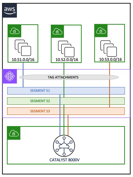
Note: AWS VPCs are mapped to CNE Segments using tag-based attachments.
Step 1. (Optional step, only applicable when the cloud routers have been deployed in another account as the account containing the workload VPCs) Repeat all the steps from the procedure Associate Cloud Account to associate new AWS account(s) with SD-WAN Manager. Once the AWS account is provisioned in SD-WAN Manager, proceed to the next step.
Step 2. From the Cisco SD-WAN Manager menu, click Configuration > Cloud OnRamp for Multicloud. Navigate to the bottom of the page and select Host Private Networks.
Step 3. In the Discover Host Private Networks menu, SDWAN Manager will query all associated cloud accounts for any configured VPCs. Select the appropriate host VPC for attachment.
Step 4. On the left-hand side of the VPC overview, select the checkbox for the appropriate workload VPC and select Tag Actions > Add Tag.
Step 5. In the Add New Tag menu, provide a Tag Name followed by selecting Add.
Note: This step can be repeated for any additional VPCs.
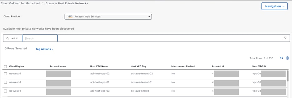
Step 6. Wait until the Adding Tag process has been completed successfully.
Note: This design guide uses three tags: aci-aws-tenant-01, aci-aws-tenant-02, aci-aws-shared. These tags are mapped to three VPNs: 51, 52 and 53.
Step 7. In Cisco SD-WAN Manager menu, navigate to Configuration > Cloud OnRamp for Multicloud. In the Cloud Onramp for Multicloud window, navigate to the bottom of the page and select Cloud Connectivity from the Intent Management menu.
Step 8. In the Interconnect Connectivity menu, perform the following actions:
a. In the Cloud Provider drop-down list, select Amazon Web Services.
b. Select Edit.
c. The intent menu allows the administrator to configure bindings between the workload VPCs based on their tag to their matching VRFs. Create the appropriate mappings (an example is provided in the screenshot below).
d. Click Save to apply the changes.
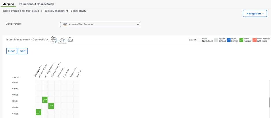
Verification
ACI Route Table Verification
The following output from the ACI border leaf nodes can be used to verify connectivity from each VRF in ACI to each SD-WAN VPN.
| tenant-01 route table information
leaf-101# show ip route vrf tenant-01:vrf-01 IP Route Table for VRF "tenant-01:vrf-01"
10.51.0.0/16, ubest/mbest: 2/0 *via 10.20.51.2%tenant-01:vrf-01, [20/1000], 01w03d, bgp-65004, external, tag 65151 *via 10.30.51.2%tenant-01:vrf-01, [20/1000], 01w03d, bgp-65004, external, tag 65151 172.16.100.0/24, ubest/mbest: 1/0, attached, direct, pervasive *via 10.0.8.66%overlay-1, [1/0], 01w03d, static 172.16.100.1/32, ubest/mbest: 1/0, attached, pervasive *via 172.16.100.1, vlan1, [0/0], 01w03d, local, local 172.16.101.0/24, ubest/mbest: 1/0, attached, direct, pervasive *via 10.0.8.66%overlay-1, [1/0], 01w03d, static, tag 4294967294 172.16.101.1/32, ubest/mbest: 1/0, attached, pervasive *via 172.16.101.1, vlan73, [0/0], 01w03d, local, local 172.16.102.0/24, ubest/mbest: 1/0, attached, direct, pervasive *via 10.0.8.66%overlay-1, [1/0], 01w03d, static, tag 4294967294 172.16.102.1/32, ubest/mbest: 1/0, attached, pervasive *via 172.16.102.1, vlan3, [0/0], 01w03d, local, local leaf-101#
leaf-102# show ip route vrf tenant-01:vrf-01 IP Route Table for VRF "tenant-01:vrf-01"
10.51.0.0/16, ubest/mbest: 2/0 *via 10.20.51.6%tenant-01:vrf-01, [20/1000], 01w03d, bgp-65004, external, tag 65151 *via 10.30.51.6%tenant-01:vrf-01, [20/1000], 01w03d, bgp-65004, external, tag 65151 172.16.100.0/24, ubest/mbest: 1/0, attached, direct, pervasive *via 10.0.8.66%overlay-1, [1/0], 01w03d, static 172.16.100.1/32, ubest/mbest: 1/0, attached, pervasive *via 172.16.100.1, vlan54, [0/0], 01w03d, local, local 172.16.101.0/24, ubest/mbest: 1/0, attached, direct, pervasive *via 10.0.8.66%overlay-1, [1/0], 01w03d, static, tag 4294967294 172.16.101.1/32, ubest/mbest: 1/0, attached, pervasive *via 172.16.101.1, vlan48, [0/0], 01w03d, local, local 172.16.102.0/24, ubest/mbest: 1/0, attached, direct, pervasive *via 10.0.8.66%overlay-1, [1/0], 01w03d, static, tag 4294967294 172.16.102.1/32, ubest/mbest: 1/0, attached, pervasive *via 172.16.102.1, vlan56, [0/0], 01w03d, local, local leaf-102# |
| tenant-02 route table information
leaf-101# show ip route vrf tenant-02:vrf-01 IP Route Table for VRF "tenant-02:vrf-01"
10.52.0.0/16, ubest/mbest: 2/0 *via 10.30.52.2%tenant-02:vrf-01, [20/1000], 00:17:01, bgp-65004, external, tag 65151 *via 10.20.52.2%tenant-02:vrf-01, [20/1000], 00:17:01, bgp-65004, external, tag 65151 172.16.100.0/24, ubest/mbest: 1/0, attached, direct, pervasive *via 10.0.8.66%overlay-1, [1/0], 01w03d, static, tag 4294967292, rwVnid: vxlan-2424838
leaf-101# show ip route vrf tenant-02:vrf-02 IP Route Table for VRF "tenant-02:vrf-02"
10.52.0.0/16, ubest/mbest: 2/0 *via 10.30.52.2%tenant-02:vrf-01, [20/1000], 00:18:38, bgp-65004, external, tag 65151, rwVnid: vxlan-2621445 *via 10.20.52.2%tenant-02:vrf-01, [20/1000], 00:18:38, bgp-65004, external, tag 65151, rwVnid: vxlan-2621445 172.16.100.0/24, ubest/mbest: 1/0, attached, direct, pervasive *via 10.0.8.66%overlay-1, [1/0], 01w03d, static, rwVnid: vxlan-2424838 172.16.100.1/32, ubest/mbest: 1/0, attached, pervasive ( *via 172.16.100.1, vlan37, [0/0], 01w03d, local, local 172.16.101.0/24, ubest/mbest: 1/0, attached, direct, pervasive *via 10.0.8.66%overlay-1, [1/0], 01w03d, static, tag 4294967294 172.16.101.1/32, ubest/mbest: 1/0, attached, pervasive *via 172.16.101.1, vlan26, [0/0], 01w03d, local, local 172.16.102.0/24, ubest/mbest: 1/0, attached, direct, pervasive *via 10.0.8.66%overlay-1, [1/0], 01w03d, static, tag 4294967294 172.16.102.1/32, ubest/mbest: 1/0, attached, pervasive *via 172.16.102.1, vlan22, [0/0], 01w03d, local, local
leaf-102# show ip route vrf tenant-02:vrf-01 IP Route Table for VRF "tenant-02:vrf-01"
10.52.0.0/16, ubest/mbest: 2/0 *via 10.30.52.6%tenant-02:vrf-01, [20/1000], 00:23:53, bgp-65004, external, tag 65151 *via 10.20.52.6%tenant-02:vrf-01, [20/1000], 00:23:54, bgp-65004, external, tag 65151 172.16.100.0/24, ubest/mbest: 1/0, attached, direct, pervasive *via 10.0.8.66%overlay-1, [1/0], 01w03d, static, tag 4294967292, rwVnid: vxlan-2424838
leaf-102# show ip route vrf tenant-02:vrf-01 IP Route Table for VRF "tenant-02:vrf-01"
10.52.0.0/16, ubest/mbest: 2/0 *via 10.30.52.6%tenant-02:vrf-01, [20/1000], 00:19:58, bgp-65004, external, tag 65151 *via 10.20.52.6%tenant-02:vrf-01, [20/1000], 00:19:59, bgp-65004, external, tag 65151 172.16.100.0/24, ubest/mbest: 1/0, attached, direct, pervasive *via 10.0.8.66%overlay-1, [1/0], 01w03d, static, tag 4294967292, rwVnid: vxlan-2424838
leaf-102# show ip route vrf tenant-02:vrf-02 IP Route Table for VRF "tenant-02:vrf-02"
10.52.0.0/16, ubest/mbest: 2/0 *via 10.30.52.6%tenant-02:vrf-01, [20/1000], 00:20:31, bgp-65004, external, tag 65151, rwVnid: vxlan-2621445 *via 10.20.52.6%tenant-02:vrf-01, [20/1000], 00:20:32, bgp-65004, external, tag 65151, rwVnid: vxlan-2621445 172.16.100.0/24, ubest/mbest: 1/0, attached, direct, pervasive *via 10.0.8.66%overlay-1, [1/0], 01w03d, static, rwVnid: vxlan-2424838 172.16.100.1/32, ubest/mbest: 1/0, attached, pervasive *via 172.16.100.1, vlan69, [0/0], 01w03d, local, local 172.16.101.0/24, ubest/mbest: 1/0, attached, direct, pervasive *via 10.0.8.66%overlay-1, [1/0], 01w03d, static, tag 4294967294 172.16.101.1/32, ubest/mbest: 1/0, attached, pervasive *via 172.16.101.1, vlan59, [0/0], 01w03d, local, local 172.16.102.0/24, ubest/mbest: 1/0, attached, direct, pervasive *via 10.0.8.66%overlay-1, [1/0], 01w03d, static, tag 4294967294 172.16.102.1/32, ubest/mbest: 1/0, attached, pervasive *via 172.16.102.1, vlan73, [0/0], 01w03d, local, local |
| Shared-services route table information (continued)
leaf-102# show ip route vrf shared-services:vrf-01 IP Route Table for VRF "shared-services:vrf-01"
10.53.0.0/16, ubest/mbest: 2/0 *via 10.30.53.6%shared-services:vrf-01, [20/1000], 00:26:16, bgp-65004, external, tag 65151 *via 10.20.53.6%shared-services:vrf-01, [20/1000], 00:26:17, bgp-65004, external, tag 65151 192.168.100.0/24, ubest/mbest: 1/0, attached, direct, pervasive *via 10.0.8.66%overlay-1, [1/0], 01w03d, static, tag 4294967292, rwVnid: vxlan-2195457 192.168.200.0/24, ubest/mbest: 1/0, attached, direct, pervasive *via 10.0.8.66%overlay-1, [1/0], 01w03d, static, tag 4294967292, rwVnid: vxlan-3112964
leaf-102# show ip route vrf tenant-03:vrf-01 IP Route Table for VRF "tenant-03:vrf-01"
10.53.0.0/16, ubest/mbest: 2/0e *via 10.30.53.6%shared-services:vrf-01, [20/1000], 00:27:20, bgp-65004, external, tag 65151, rwVnid: vxlan-2949126e *via 10.20.53.6%shared-services:vrf-01, [20/1000], 00:27:21, bgp-65004, external, tag 65151, rwVnid: vxlan-2949126e192.168.100.0/24, ubest/mbest: 1/0, attached, direct, pervasivee *via 10.0.8.66%overlay-1, [1/0], 01w03d, static, rwVnid: vxlan-2195457e192.168.100.1/32, ubest/mbest: 1/0, attached, pervasivee *via 192.168.100.1, vlan86, [0/0], 01w03d, local, locale192.168.101.0/24, ubest/mbest: 1/0, attached, direct, pervasive *via 10.0.8.66%overlay-1, [1/0], 01w03d, static, tag 4294967294 192.168.101.1/32, ubest/mbest: 1/0, attached, pervasive *via 192.168.101.1, vlan44, [0/0], 01w03d, local, local 192.168.102.0/24, ubest/mbest: 1/0, attached, direct, pervasive *via 10.0.8.66%overlay-1, [1/0], 01w03d, static, tag 4294967294 192.168.102.1/32, ubest/mbest: 1/0, attached, pervasive *via 192.168.102.1, vlan88, [0/0], 01w03d, local, local
leaf-102# show ip route vrf tenant-04:vrf-01 IP Route Table for VRF "tenant-04:vrf-01"
10.53.0.0/16, ubest/mbest: 2/0 *via 10.30.53.6%shared-services:vrf-01, [20/1000], 00:27:23, bgp-65004, external, tag 65151, rwVnid: vxlan-2949126 *via 10.20.53.6%shared-services:vrf-01, [20/1000], 00:27:24, bgp-65004, external, tag 65151, rwVnid: vxlan-2949126 192.168.200.0/24, ubest/mbest: 1/0, attached, direct, pervasive *via 10.0.8.66%overlay-1, [1/0], 01w03d, static, rwVnid: vxlan-3112964 192.168.200.1/32, ubest/mbest: 1/0, attached, pervasive *via 192.168.200.1, vlan4, [0/0], 01w03d, local, local 192.168.201.0/24, ubest/mbest: 1/0, attached, direct, pervasive *via 10.0.8.66%overlay-1, [1/0], 01w03d, static, tag 4294967294 192.168.201.1/32, ubest/mbest: 1/0, attached, pervasive *via 192.168.201.1, vlan90, [0/0], 01w03d, local, local 192.168.202.0/24, ubest/mbest: 1/0, attached, direct, pervasive *via 10.0.8.66%overlay-1, [1/0], 01w03d, static, tag 4294967294 192.168.202.1/32, ubest/mbest: 1/0, attached, pervasive *via 192.168.202.1, vlan2, [0/0], 01w03d, local, local |
SD-WAN Routing
C8000V Route Table Verification
| tenant-01 route table information
aws-us-west-aci-r01#sh ip route vrf 51 10.0.0.0/8 is variably subnetted, 5 subnets, 2 masks m 10.20.51.0/30 [251/0] via 4.4.4.3, 2d06h, Sdwan-system-intf m 10.20.51.4/30 [251/0] via 4.4.4.3, 2d04h, Sdwan-system-intf m 10.30.51.0/30 [251/0] via 4.4.4.4, 2d06h, Sdwan-system-intf m 10.30.51.4/30 [251/0] via 4.4.4.4, 2d04h, Sdwan-system-intf B 10.51.0.0/16 [20/100] via 169.254.2.27, 1d23h [20/100] via 169.254.2.26, 1d23h 169.254.0.0/16 is variably subnetted, 2 subnets, 2 masks C 169.254.2.24/29 is directly connected, Tunnel100524 L 169.254.2.25/32 is directly connected, Tunnel100524 172.16.0.0/24 is subnetted, 1 subnets m 172.16.100.0 [251/0] via 4.4.4.4, 2w5d, Sdwan-system-intf [251/0] via 4.4.4.3, 2w5d, Sdwan-system-intf
!10.51.0.0/16 is the VPC subnet received in VRF 51, NH is the GRE Tunnel IP on CNE !172.16.100.0/24 is the ACI prefix exported from tenant-01, NH is the TLOC on C8500 |
| tenant-02 route table information
aws-us-west-aci-r01#sh ip route vrf 52 10.0.0.0/8 is variably subnetted, 5 subnets, 2 masks m 10.20.52.0/30 [251/0] via 4.4.4.3, 2d06h, Sdwan-system-intf m 10.20.52.4/30 [251/0] via 4.4.4.3, 2d04h, Sdwan-system-intf m 10.30.52.0/30 [251/0] via 4.4.4.4, 2d06h, Sdwan-system-intf m 10.30.52.4/30 [251/0] via 4.4.4.4, 2d04h, Sdwan-system-intf B 10.52.0.0/16 [20/100] via 169.254.2.219, 1d23h [20/100] via 169.254.2.218, 1d23h 169.254.0.0/16 is variably subnetted, 2 subnets, 2 masks C 169.254.2.216/29 is directly connected, Tunnel100528 L 169.254.2.217/32 is directly connected, Tunnel100528 172.16.0.0/24 is subnetted, 1 subnets m 172.16.100.0 [251/0] via 4.4.4.4, 2w5d, Sdwan-system-intf [251/0] via 4.4.4.3, 2w5d, Sdwan-system-intf
!10.52.0.0/16 is the VPC subnet received in VRF 52, NH is the GRE Tunnel IP on CNE !172.16.100.0/24 is the ACI prefix exported from tenant-02, NH is the TLOC on C8500 |
| Shared-services route table information
aws-us-west-aci-r01#sh ip route vrf 53 10.0.0.0/8 is variably subnetted, 5 subnets, 2 masks m 10.20.53.0/30 [251/0] via 4.4.4.3, 2d06h, Sdwan-system-intf m 10.20.53.4/30 [251/0] via 4.4.4.3, 2d04h, Sdwan-system-intf m 10.30.53.0/30 [251/0] via 4.4.4.4, 2d06h, Sdwan-system-intf m 10.30.53.4/30 [251/0] via 4.4.4.4, 2d04h, Sdwan-system-intf B 10.53.0.0/16 [20/100] via 169.254.3.163, 2d00h [20/100] via 169.254.3.162, 2d00h 169.254.0.0/16 is variably subnetted, 2 subnets, 2 masks C 169.254.3.160/29 is directly connected, Tunnel100529 L 169.254.3.161/32 is directly connected, Tunnel100529 m 192.168.100.0/24 [251/0] via 4.4.4.4, 2w5d, Sdwan-system-intf [251/0] via 4.4.4.3, 2w5d, Sdwan-system-intf m 192.168.200.0/24 [251/0] via 4.4.4.4, 2w5d, Sdwan-system-intf [251/0] via 4.4.4.3, 2w5d, Sdwan-system-intf
!10.53.0.0/16 is the VPC subnet received in VRF 53, NH is the GRE Tunnel IP on CNE !192.16.100.0/24 and 192.168.200.0/24 are the ACI prefix exported from Shared-services, NH is the TLOC on C8500 |
C8500 Route Table Verification
| tenant-01 route table information
ams-aci-r01#sh ip route vrf 51 10.0.0.0/8 is variably subnetted, 7 subnets, 3 masks C 10.20.51.0/30 is directly connected, TenGigabitEthernet0/0/5.2051 L 10.20.51.2/32 is directly connected, TenGigabitEthernet0/0/5.2051 C 10.20.51.4/30 is directly connected, TenGigabitEthernet0/0/6.2051 L 10.20.51.6/32 is directly connected, TenGigabitEthernet0/0/6.2051 m 10.30.51.0/30 [251/0] via 4.4.4.4, 2d02h, Sdwan-system-intf m 10.30.51.4/30 [251/0] via 4.4.4.4, 1d23h, Sdwan-system-intf m 10.51.0.0/16 [251/0] via 31.62.1.2, 3w1d, Sdwan-system-intf [251/0] via 31.62.1.1, 3w1d, Sdwan-system-intf 169.254.0.0/29 is subnetted, 2 subnets m 169.254.2.24 [251/0] via 31.62.1.1, 3w6d, Sdwan-system-intf m 169.254.2.32 [251/0] via 31.62.1.2, 3w1d, Sdwan-system-intf 172.16.0.0/24 is subnetted, 1 subnets B 172.16.100.0 [20/0] via 10.20.51.1, 2d00h
!10.51.0.0/16 is the VPC subnet received in VRF 51, NH is the TLOCs on C8KV !172.16.100.0/24 is the ACI prefix exported from tenant-01, NH is the ACI border leaf |
| tenant-02 route table information
ams-aci-r01#sh ip route vrf 52 10.0.0.0/8 is variably subnetted, 7 subnets, 3 masks C 10.20.52.0/30 is directly connected, TenGigabitEthernet0/0/5.2052 L 10.20.52.2/32 is directly connected, TenGigabitEthernet0/0/5.2052 C 10.20.52.4/30 is directly connected, TenGigabitEthernet0/0/6.2052 L 10.20.52.6/32 is directly connected, TenGigabitEthernet0/0/6.2052 m 10.30.52.0/30 [251/0] via 4.4.4.4, 2d02h, Sdwan-system-intf m 10.30.52.4/30 [251/0] via 4.4.4.4, 1d23h, Sdwan-system-intf m 10.52.0.0/16 [251/0] via 31.62.1.2, 3w1d, Sdwan-system-intf [251/0] via 31.62.1.1, 3w1d, Sdwan-system-intf 169.254.0.0/29 is subnetted, 2 subnets m 169.254.2.216 [251/0] via 31.62.1.1, 3w6d, Sdwan-system-intf m 169.254.2.224 [251/0] via 31.62.1.2, 3w1d, Sdwan-system-intf 172.16.0.0/24 is subnetted, 1 subnets B 172.16.100.0 [20/0] via 10.20.52.1, 2d00h
!10.52.0.0/16 is the VPC subnet received in VRF 52, NH is the TLOCs on C8KV !172.16.100.0/24 is the ACI prefix exported from tenant-02, NH is the ACI border leaf |
| Shared-services route table information
ams-aci-r01#sh ip route vrf 53 10.0.0.0/8 is variably subnetted, 7 subnets, 3 masks C 10.20.53.0/30 is directly connected, TenGigabitEthernet0/0/5.2053 L 10.20.53.2/32 is directly connected, TenGigabitEthernet0/0/5.2053 C 10.20.53.4/30 is directly connected, TenGigabitEthernet0/0/6.2053 L 10.20.53.6/32 is directly connected, TenGigabitEthernet0/0/6.2053 m 10.30.53.0/30 [251/0] via 4.4.4.4, 2d02h, Sdwan-system-intf m 10.30.53.4/30 [251/0] via 4.4.4.4, 1d23h, Sdwan-system-intf m 10.53.0.0/16 [251/0] via 31.62.1.2, 3w1d, Sdwan-system-intf [251/0] via 31.62.1.1, 3w1d, Sdwan-system-intf 169.254.0.0/29 is subnetted, 2 subnets m 169.254.3.160 [251/0] via 31.62.1.1, 3w6d, Sdwan-system-intf m 169.254.3.168 [251/0] via 31.62.1.2, 3w1d, Sdwan-system-intf B 192.168.100.0/24 [20/0] via 10.20.53.1, 2d00h B 192.168.200.0/24 [20/0] via 10.20.53.1, 2d00h
!10.53.0.0/16 is the VPC subnet received in VRF 53, NH is the TLOCs on C8KV !192.16.100.0/24 and 192.168.200.0/24 are the ACI prefix exported from Shared-services, NH is the ACI border leaf |
Summary
Cisco Catalyst SD-WAN Cloud OnRamp made it simple for enterprise customers to connect on-premises data centers to the public cloud.
This solution provides ultimate IT agility by greatly automating the WAN connectivity and network segmentation between ACI and public cloud infrastructure to build the hybrid Multicloud environment.
Furthermore, Cisco Catalyst SD-WAN provides a secure WAN fabric to connect branch, campus, data center and public cloud, simplifying the customer’s entire WAN management with a single dashboard – Catalyst SD-WAN Manager –allowing the customer to focus on the application experience and business intent.
C8000V Configuration
SD-WAN VPN 51 VRF, Tunnel to CNE and BGP config
| vrf definition 51 rd 1:51 address-family ipv4 route-target export 64570:51 route-target import 64570:51 exit-address-family ! address-family ipv6 exit-address-family ! ! interface Tunnel100524 no shutdown vrf forwarding 51 ip address 169.254.2.25 255.255.255.248 no ip clear-dont-fragment ip tcp adjust-mss 1387 ip mtu 1500 tunnel source 10.62.1.46 tunnel destination 10.62.0.86 tunnel route-via GigabitEthernet2 mandatory ! router bgp 64570 address-family ipv4 unicast vrf 51 distance bgp 20 200 20 maximum-paths eibgp 2 neighbor 169.254.2.26 remote-as 64541 neighbor 169.254.2.26 activate neighbor 169.254.2.26 ebgp-multihop 2 neighbor 169.254.2.26 route-map AWS_CNE_CSR_ROUTE_POLICY out neighbor 169.254.2.26 send-community both neighbor 169.254.2.27 remote-as 64541 neighbor 169.254.2.27 activate neighbor 169.254.2.27 ebgp-multihop 2 neighbor 169.254.2.27 route-map AWS_CNE_CSR_ROUTE_POLICY out neighbor 169.254.2.27 send-community both propagate-aspath redistribute omp exit-address-family ! route-map AWS_CNE_CSR_ROUTE_POLICY deny 1 match as-path 15 ! route-map AWS_CNE_CSR_ROUTE_POLICY permit 11 match as-path 25 ! route-map AWS_CNE_CSR_ROUTE_POLICY deny 65535 ! ip as-path access-list 15 permit ^645[4-6][0-9]$ ip as-path access-list 25 permit .* |
SD-WAN VPN 52 VRF, Tunnel to CNE and BGP config
| vrf definition 52 rd 1:52 address-family ipv4 route-target export 64570:52 route-target import 64570:52 exit-address-family ! address-family ipv6 exit-address-family ! interface Tunnel100528 no shutdown vrf forwarding 52 ip address 169.254.2.217 255.255.255.248 no ip clear-dont-fragment ip tcp adjust-mss 1387 ip mtu 1500 tunnel source 10.62.1.46 tunnel destination 10.62.0.66 tunnel route-via GigabitEthernet2 mandatory ! router bgp 64570 address-family ipv4 unicast vrf 52 distance bgp 20 200 20 maximum-paths eibgp 2 neighbor 169.254.2.218 remote-as 64541 neighbor 169.254.2.218 activate neighbor 169.254.2.218 ebgp-multihop 2 neighbor 169.254.2.218 route-map AWS_TGW_CSR_ROUTE_POLICY out neighbor 169.254.2.218 send-community both neighbor 169.254.2.219 remote-as 64541 neighbor 169.254.2.219 activate neighbor 169.254.2.219 ebgp-multihop 2 neighbor 169.254.2.219 route-map AWS_TGW_CSR_ROUTE_POLICY out neighbor 169.254.2.219 send-community both propagate-aspath redistribute omp exit-address-family |
SD-WAN VPN 53 VRF, Tunnel to CNE and BGP config
| vrf definition 53 rd 1:53 address-family ipv4 route-target export 64570:53 route-target import 64570:53 exit-address-family ! address-family ipv6 exit-address-family ! interface Tunnel100529 no shutdown vrf forwarding 53 ip address 169.254.3.161 255.255.255.248 no ip clear-dont-fragment ip tcp adjust-mss 1387 ip mtu 1500 tunnel source 10.62.1.46 tunnel destination 10.62.0.48 tunnel route-via GigabitEthernet2 mandatory ! router bgp 64570 address-family ipv4 unicast vrf 53 distance bgp 20 200 20 maximum-paths eibgp 2 neighbor 169.254.3.162 remote-as 64541 neighbor 169.254.3.162 activate neighbor 169.254.3.162 ebgp-multihop 2 neighbor 169.254.3.162 route-map AWS_TGW_CSR_ROUTE_POLICY out neighbor 169.254.3.162 send-community both neighbor 169.254.3.163 remote-as 64541 neighbor 169.254.3.163 activate neighbor 169.254.3.163 ebgp-multihop 2 neighbor 169.254.3.163 route-map AWS_TGW_CSR_ROUTE_POLICY out neighbor 169.254.3.163 send-community both propagate-aspath redistribute omp exit-address-family |
SD-WAN Underlay Transport Interface, Overlay Tunnel Interface, OMP, BFD and IPsec config
| interface GigabitEthernet2 no shutdown arp timeout 1200 ip address dhcp client-id GigabitEthernet2 no ip redirects ip dhcp client default-router distance 1 ip mtu 1500 load-interval 30 mtu 1500 negotiation auto ! interface Tunnel2 no shutdown ip unnumbered GigabitEthernet2 no ip redirects ipv6 unnumbered GigabitEthernet2 no ipv6 redirects tunnel source GigabitEthernet2 tunnel mode sdwan ! sdwan interface GigabitEthernet2 tunnel-interface encapsulation ipsec weight 1 no border color public-internet no last-resort-circuit no low-bandwidth-link no vbond-as-stun-server vmanage-connection-preference 5 no port-hop carrier default nat-refresh-interval 5 hello-interval 1000 hello-tolerance 12 allow-service all no allow-service bgp allow-service dhcp allow-service dns allow-service icmp allow-service sshd no allow-service netconf no allow-service ntp no allow-service ospf no allow-service stun allow-service https no allow-service snmp no allow-service bfd ! omp no shutdown send-path-limit 4 ecmp-limit 4 graceful-restart no as-dot-notation timers holdtime 60 advertisement-interval 1 graceful-restart-timer 43200 eor-timer 300 exit address-family ipv4 advertise bgp advertise connected advertise static ! address-family ipv6 advertise bgp advertise connected advertise static ! bfd default-dscp 48 bfd app-route multiplier 2 bfd app-route poll-interval 123400 security ipsec rekey 86400 replay-window 512 ! |
C8500 Configuration
SD-WAN VPN 51 VRF, (sub)interface to ACI border leaf and BGP config
| vrf definition 51 description tenant-01 rd 1:51 address-family ipv4 route-target export 65051:51 route-target import 65051:51 exit-address-family ! address-family ipv6 exit-address-family ! ! interface TenGigabitEthernet0/0/5 no ip address ! interface TenGigabitEthernet0/0/5.2051 encapsulation dot1Q 2051 vrf forwarding 51 ip address 10.20.51.2 255.255.255.252 no ip redirects arp timeout 1200 ! interface TenGigabitEthernet0/0/6 no ip address ! interface TenGigabitEthernet0/0/6.2051 encapsulation dot1Q 2051 vrf forwarding 51 ip address 10.20.51.6 255.255.255.252 no ip redirects arp timeout 1200 ! router bgp 65051 address-family ipv4 vrf 51 redistribute connected redistribute omp neighbor 10.20.51.1 remote-as 65151 neighbor 10.20.51.1 description tenant-01 neighbor 10.20.51.1 activate neighbor 10.20.51.1 send-community both neighbor 10.20.51.5 remote-as 65151 neighbor 10.20.51.5 description tenant-01 neighbor 10.20.51.5 activate neighbor 10.20.51.5 send-community both distance bgp 20 200 20 exit-address-family |
SD-WAN VPN 52 VRF, (sub)interface to ACI border leaf and BGP config
| vrf definition 52 description tenant-02 rd 1:52 address-family ipv4 route-target export 65051:52 route-target import 65051:52 exit-address-family ! address-family ipv6 exit-address-family ! interface TenGigabitEthernet0/0/5 no ip address ! interface TenGigabitEthernet0/0/5.2052 encapsulation dot1Q 2052 vrf forwarding 52 ip address 10.20.52.2 255.255.255.252 no ip redirects arp timeout 1200 ! interface TenGigabitEthernet0/0/6 no ip address ! interface TenGigabitEthernet0/0/6.2052 encapsulation dot1Q 2052 vrf forwarding 52 ip address 10.20.52.6 255.255.255.252 no ip redirects arp timeout 1200 ! router bgp 65051 address-family ipv4 vrf 52 redistribute connected redistribute omp neighbor 10.20.52.1 remote-as 65151 neighbor 10.20.52.1 description tenant-02 neighbor 10.20.52.1 activate neighbor 10.20.52.1 send-community both neighbor 10.20.52.5 remote-as 65151 neighbor 10.20.52.5 description tenant-02 neighbor 10.20.52.5 activate neighbor 10.20.52.5 send-community both distance bgp 20 200 20 exit-address-family |
VPN 53 VRF, (sub)interface to ACI border leaf and BGP config
| vrf definition 53 description SHARED rd 1:53 address-family ipv4 route-target export 65051:53 route-target import 65051:53 exit-address-family ! address-family ipv6 exit-address-family exit-address-family ! interface TenGigabitEthernet0/0/5 no ip address ! interface TenGigabitEthernet0/0/5.2053 encapsulation dot1Q 2053 vrf forwarding 53 ip address 10.20.53.2 255.255.255.252 no ip redirects arp timeout 1200 ! interface TenGigabitEthernet0/0/6 no ip address ! interface TenGigabitEthernet0/0/6.2052 encapsulation dot1Q 2053 vrf forwarding 53 ip address 10.20.53.6 255.255.255.252 no ip redirects arp timeout 1200 ! router bgp 65051 address-family ipv4 vrf 53 redistribute connected redistribute omp neighbor 10.20.53.1 remote-as 65151 neighbor 10.20.53.1 description SHARED neighbor 10.20.53.1 activate neighbor 10.20.53.1 send-community both neighbor 10.20.53.5 remote-as 65151 neighbor 10.20.53.5 description SHARED neighbor 10.20.53.5 activate neighbor 10.20.53.5 send-community both distance bgp 20 200 20 exit-address-family |
SD-WAN Underlay Transport Interface, Overlay Tunnel Interface, OMP, BFD and IPsec config
| interface TenGigabitEthernet0/0/7 no ip address ! interface TenGigabitEthernet0/0/7.1025 encapsulation dot1Q 1025 ip address 173.38.154.243 255.255.255.240 no ip redirects arp timeout 1200 ! interface Tunnel11025007 no shutdown ip unnumbered TenGigabitEthernet0/0/7.1025 no ip redirects ipv6 unnumbered TenGigabitEthernet0/0/7.1025 no ipv6 redirects tunnel source TenGigabitEthernet0/0/7.1025 tunnel mode sdwan ! sdwan interface TenGigabitEthernet0/0/7.1025 tunnel-interface encapsulation ipsec weight 1 no border color public-internet no last-resort-circuit no low-bandwidth-link no vbond-as-stun-server vmanage-connection-preference 5 no port-hop carrier default nat-refresh-interval 5 hello-interval 1000 hello-tolerance 12 allow-service all allow-service bgp allow-service dhcp allow-service dns allow-service icmp allow-service sshd allow-service netconf allow-service ntp allow-service ospf allow-service stun allow-service https allow-service snmp no allow-service bfd ! omp no shutdown send-path-limit 4 ecmp-limit 4 graceful-restart no as-dot-notation timers holdtime 60 advertisement-interval 1 graceful-restart-timer 43200 eor-timer 300 exit address-family ipv4 advertise bgp advertise connected advertise static ! address-family ipv6 advertise connected advertise static ! bfd default-dscp 48 bfd app-route multiplier 6 bfd app-route poll-interval 600000 security ipsec rekey 86400 replay-window 512 ! |