About the Secure Firewall Management Center 1800, 2800, and 4800
The provides centralized, integrated, and streamlined management of threat defense devices. It also provides application control, intrusion prevention system (IPS), URL filtering, and malware protection functions. In a typical deployment on a large network, you install multiple managed threat defense devices on network segments. Each device controls, inspects, monitors, and analyzes traffic, and then reports to a .
The Secure Firewall Management Center 1800, 2800, and 4800 appliances provide significant performance and efficiency.
This document explains how to complete the cabling and the initial configuration of the .
Before You Begin
Install the management center. For more information, see the Cisco Secure Firewall Management Center 1800, 2800, and 4800 Hardware Installation Guide.
For a complete list of the Cisco Secure Firewall series documentation and where to find it, see the documentation roadmap.
End-to-End Procedure
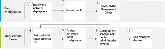
The following flowchart illustrates the tasks to deploy and configure the management center.
|
|
Pre-Configuration |
|
|
|
Pre-Configuration |
|
|
|
Pre-Configuration |
|
|
|
|
|
|
|
|
|
|
|
|
|
|
|
|
Review Network Deployment
Before you deploy the , you need information about the environment in which it operates.
The following figure shows a typical network deployment for a management center.
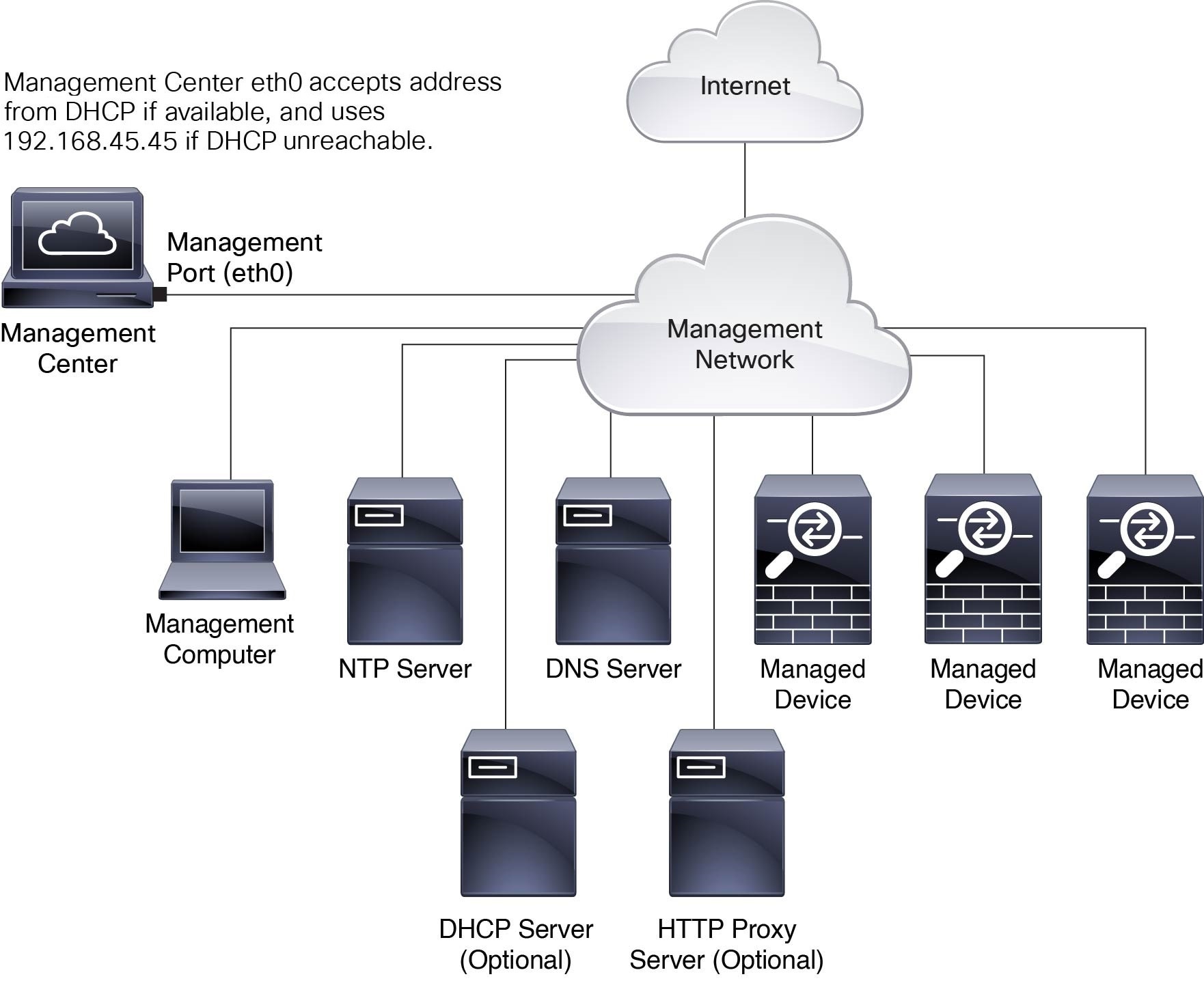
By default, the connects to your local management network through its management interface (eth0). This connection the communicates with a management computer, managed devices, services such as DHCP, DNS, NTP, and the internet.
The requires internet access to support Smart Licensing, Secure Firewall Threat Intelligence Director, and malware defense services. Depending on the services provided by your local management network, the may also require internet access to reach an NTP or DNS server. You can configure your network to provide internet access to the directly or through a firewall device.
You can upload updates for system software, Vulnerability Database (VDB), Geolocation Database (GeoDB), and intrusion rules directly to the from an internet connection or from a local computer that has these updates from the internet.
To establish the connection between the and one of its managed devices, you need the IP address of at least one of the devices: the or the managed device. We recommend using both IP addresses if available. However, you may only know one IP address. For example, managed devices may be using private addresses behind NAT, so you only know the address. In this case, you can specify the address on the managed device plus a one-time, unique password of your choice called a NAT ID. On the , you specify the same NAT ID to identify the managed device.
The initial setup and configuration described in this document is for a that has internet access. If you deploy a in an air-gapped environment, see the Cisco Secure Firewall Management Center Administration Guide for your version for alternative methods you can use to support certain features such as configuring a proxy for HTTP communications, or using a Smart Software Satellite Server for Smart Licensing.
Initial Network Configuration for s
-
Management Interface
By default, the seeks out a local DHCP server for the IP address, network mask, and default gateway to use for the management interface (eth0). If the cannot reach a DHCP server, it uses the default IPv4 address 192.168.45.45, netmask 255.255.255.0, and gateway 192.168.45.1. During the initial setup, you can accept these defaults or specify different values.

Note
If you use DHCP, you must use DHCP reservation, so the assigned address does not change. If the DHCP address changes, device registration will fail because the network configuration gets out of sync. To recover from a DHCP address change, connect to the (using the hostname or the new IP address) and navigate to , and then click Management Interfaces to reset the network.
If you use IPv6 addressing for the management interface, you must configure the address using the web interface after completing the initial setup.
-
DNS Servers
Specify IP addresses for up to two DNS servers. If you use an evaluation license, you may choose not to use DNS.
Note
During initial configuration, you can also provide a hostname and domain to facilitate communication between the and other hosts through DNS; you can configure more domains after completing the initial setup.
-
NTP Servers
Synchronize the system time on your and its managed devices during initial configuration. You can accept the default (0.sourcefire.pool.ntp.org and 1.sourcefire.pool.ntp.org as the primary and secondary NTP servers, respectively), or supply FQDNs or IP addresses for one or two trusted NTP servers reachable from your network. If you do not use DNS, you cannot use FQDNs to specify the NTP servers.
Cable the Management Center
You can cable the management center using one of the two connections listed below:
-
Connect a keyboard to the USB port and a monitor to the VGA port of the management center. By default, the management center sends console messages to the VGA port.
-
Connect the management center CIMC port to a local network reachable from a local computer where you can run an IPMI utility for Lights-Out Management. To use this connection see Set Up Light-Out Management.
AC power supplies have internal grounding so no additional chassis grounding is required when the supported AC power cords are used. For more information about supported power cords, see the Cisco Secure Firewall Management Center 1800, 2800, and 4800 Hardware Installation Guide.
After rack-mounting the chassis, follow these steps to connect the cables.
Before you begin
Important |
Read the Regulatory and Compliance Safety Information document before installing the management center chassis. |
Rack-mount the appliance as described in the Cisco Secure Firewall Management Center 1800, 2800, and 4800 Hardware Installation Guide.
If you plan to cable the appliance using the console port and a local computer, redirect the console output to the console port. For more information, see Redirect the Console Output Using the Web Interface and Redirect the Console Output Using the CLI.
Procedure
|
Step 1 |
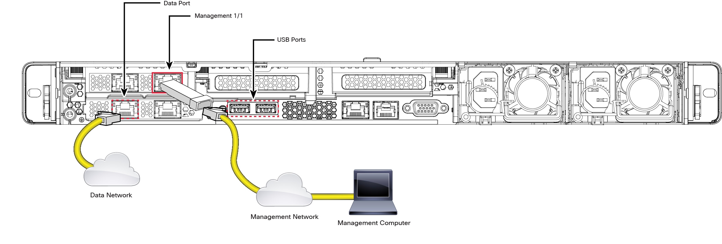
Cable the following to your management network:
|
||
|
Step 2 |
Connect the management computer to the console port using a SFP+ transceiver and cable in the 10-Gigabit Ethernet SFP+ interface for management center 1800, 2800, and 4800, or the 25-Gigabit Ethernet SFP+ interface for management center 4800. Use the console port to access the CLI for initial setup. |
||
|
Step 3 |
Use a terminal emulation software (such as HyperTerminal or XModem) on the local computer to interact with the management center. Set the terminal emulator for 9600 baud, 8 data bits, no parity, 1 stop bit, and no flow control. |
||
|
Step 4 |
Install any supported SFP+ transceiver and cable in the 10-Gigabit Ethernet SFP+ interface for management center 1800, 2800, and 4800, or the 25-Gigabit Ethernet SFP+ interface for management center 4800. Connect this interface to the same or different network from your other management interfaces depending on your network needs.
|
What to do next
Power on the Management Center
The management center 1800, 2800, and 4800 appliances use 1200-W AC power supplies. For more information about the power supplies and the supported power cords, see the Cisco Secure Firewall Management Center 1800, 2800, and 4800 Hardware Installation Guide.
Before you begin
It is important that you provide reliable power for your device, for example, use an uninterruptable power supply (UPS). Loss of power without first shutting down the chassis can cause serious file system damage.
Procedure
|
Step 1 |
Use one of the supported power cords to connect the power supplies of the chassis to your power source.
|
||
|
Step 2 |
Press the Power button (labeled "1") on the front of the chassis, and verify that the power supply status LED (labeled "2") is on. 
|
Access the CLI or the Linux Shell on the
 Caution |
We strongly recommend that you do not use the Linux shell unless directed by Cisco TAC or explicit instructions in the user documentation. |
Before you begin
Establish a direct physical connection with the using the serial port, a keyboard and monitor, or establish an SSH session with the interface.
Procedure
|
Step 1 |
Log in to the using the credentials for the CLI admin user. This action gives you access to the CLI. |
|
Step 2 |
Use the show version command to verify the software version. Example: |
|
Step 3 |
To access the Linux shell from the CLI, enter the expert command. |
Shutdown or Restart the Firewall Management Center
Use the web interface to initiate an orderly shutdown or restart.
You can also shut down the Firewall Management Center using the system shutdown command from the Firewall Management Center CLI.
 Tip |
For virtual devices, see the documentation for your virtual platform. For VMware in particular, custom power options are part of VMware Tools. |
Caution |
Do not shutdown the Firewall Management Center using the power button; this action can cause data loss. Using the web interface or the shutdown command prepares the system to safely power off and restart without losing configuration data. |
Procedure
|
Step 1 |
Log in to your management center, choose . |
|
Step 2 |
Choose one of the following:
|
Perform Initial Setup of the Using the CLI
You can also perform the initial setup using the CLI. You must complete an Initial Configuration Wizard that configures the new appliance to communicate on your trusted management network.
Before you begin
-
Cable the as described in Cable the Management Center.
-
Ensure that you have the following information for the to communicate on your management network:
-
An IPv4 management IP address
-
A network mask and a default gateway (if not using DHCP)
-
-
Connect to the using one of three methods:
-
Connect a USB keyboard and VGA monitor to the for console access.
-
Connect a local computer to the serial port with an RJ-45 to DP-9 console cable.
-
After configuring the IP using the above two methods, access the device using SSH to connect to the using the IPv4 management IP address.
-
Procedure
|
Step 1 |
Log in to the at the console using admin as the username and Admin123 as the password for the admin account. The password is case-sensitive. |
||||
|
Step 2 |
When prompted, press Enter to display the End User License Agreement (EULA). |
||||
|
Step 3 |
Review the EULA. When prompted, enter yes, YES, or press Enter to accept the EULA.
|
||||
|
Step 4 |
To ensure system security and privacy, the first time you log in to the you are required to change the admin password. When the system prompts for a new password, enter a new password complying with the restrictions, and enter the same password again when the system prompts for confirmation.
|
||||
|
Step 5 |
Configure the network settings. When you follow the prompts, your options appear in parentheses such as (y/n). Defaults are listed in square brackets such as [y]. Note the following when responding to the prompts:
Example: |
||||
|
Step 6 |
Review the settings. The system displays a summary of the configurations. Example: |
||||
|
Step 7 |
Confirm the settings.
Example: |
||||
|
Step 8 |
After you accept the settings, you can enter exit to exit the CLI. |
What to do next
-
Connect to the web interface using the network information that you have configured.
-
Review the weekly maintenance activities that the configures automatically as part of the initial configuration process. These activities are designed to keep your system up to date and your data backed up. For more information, see Review Automatic Initial Configuration .
-
Configure the for IPv6 addressing after completing the initial setup using the web interface, if required. For more information, see Cisco Secure Firewall Management Center Device Configuration Guide.
-
(Optional) Configure the for SOL or LOM access as described in Set Up Light-Out Management.
Redirect the Console Output Using the Web Interface
You must be an Admin user to perform this procedure.
Before you begin
-
Complete the initial setup process of the appliance.
-
Disable Spanning Tree Protocol (STP) on any third-party switching equipment connected to the device's management interface.
Procedure
|
Step 1 |
Choose . |
|
Step 2 |
Choose . |
|
Step 3 |
Select a remote console access option:
|
|
Step 4 |
Click Save. |
Redirect the Console Output Using the CLI
Before you begin
Complete the initial setup process of the .
Procedure
|
Step 1 |
Use the CLI admin credentials to access the Linux shell on the . For more information, see Access the CLI or the Linux Shell on the. |
|
Step 2 |
At the prompt, use one of the following commands to set the console output:
|
|
Step 3 |
To implement your changes, reboot the appliance by using the |
Reset the CLI Admin Password
You can change the password for the admin account to access the CLI.
Before you begin
To reset the admin password, you must establish a console connection with the appliance.
Procedure
|
Step 1 |
Log in to the CLI as the admin user. |
||
|
Step 2 |
In the console, choose . 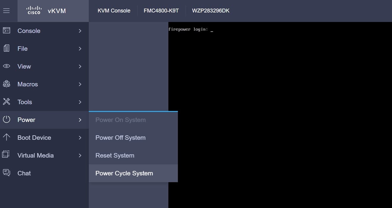 The following messages appear in the console: 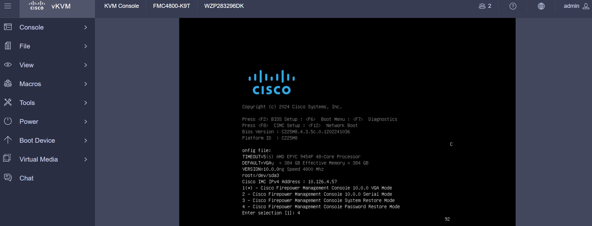 |
||
|
Step 3 |
Enter option 4 to reset the password. |
||
|
Step 4 |
At the # prompt, enter the passwd admin command. 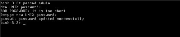 |
||
|
Step 5 |
Enter the new admin password.
|
||
|
Step 6 |
Enter the reboot command. Allow the reboot process to complete. |
Reset the Web Interface Admin Password
You can change the password for the admin account to access the web interface.
Procedure
|
Step 1 |
Log in to the web interface for the as the admin user. To reset the admin password, you need to establish a console connection with the appliance. |
||
|
Step 2 |
To access the Linux shell, enter the expert command. |
||
|
Step 3 |
At the shell prompt, enter the sudo usertool.pl -p "admin password" command. Here password is the new password for the web interface admin user. In the following example, the password is SourcefireM1!. 
|
||
|
Step 4 |
At the Password: command, enter the existing login user password. |
Review Automatic Initial Configuration
As part of the initial configuration, the automatically configures maintenance tasks to keep your system up-to-date and your data backed up.
These tasks are scheduled in UTC, which means that when they occur locally depends on the date and your specific location. As the tasks are scheduled in UTC, they do not adjust for daylight saving time, summer time, or any such seasonal adjustments that you may observe in your location. If you are affected, scheduled tasks occur one hour later in the summer than in the winter, according to local time.
Note |
We strongly recommend you review the auto-scheduled configurations, confirm that the has established them successfully, and adjust them if necessary. |
|
Task |
Description |
GUI Path |
More Info |
|---|---|---|---|
|
Weekly GeoDB updates |
GeoDB is a database to view and filter traffic based on the geographical location. |
, click Geolocation Updates tab, and then use Recurring Geolocation Updates radio button. |
Cisco Secure Firewall Management Center Administration Guide |
|
Weekly software updates |
The automatically schedules a weekly task to download the latest software for the and its managed devices. |
||
|
Weekly configuration backup |
The automatically schedules a weekly task to perform a locally stored configuration-only backup. |
Cisco Secure Firewall Management Center Administration Guide |
|
|
Vulnerability database update |
The downloads and installs the latest vulnerability database (VDB) update from the Cisco support site. This is a one-time operation. |
, click VDB Updates tab. |
Cisco Secure Firewall Management Center Administration Guide |
|
Daily intrusion rule update |
The configures a daily automatic intrusion rule update from the Cisco support site. The deploys automatic intrusion rule updates to the affected managed devices when it next deploys affected policies. |
, click Rule Updates tab. |
Configure Administrative Settings
After you complete the initial setup for the and verify its success, we recommend that you complete some administrative tasks for your deployment. You must complete any tasks that you skipped during the initial setup, such as licensing. Establish these configurations using the default admin account or another account with Administrator access.
In a NAT environment where multiple Firewall Management Centers share the same IP address and are differentiated by port numbers. Note the following conditions:
-
Each Firewall Management Center can support only one login session at a time.
-
To access different Firewall Management Centers, use a different browser for each login (for example Firefox and Chrome), or set the browser to incognito or private mode.
Procedure
|
Step 1 |
Log in to your . |
||||||||||
|
Step 2 |
In the Username and Password fields, enter your username and password. |
||||||||||
|
Step 3 |
Click Login. |
||||||||||
|
Step 4 |
Configure the following administrative tasks:
|
Add Managed Devices to the
For each managed device, use these instructions to establish a simple deployment that does not include multitenancy, clusters, or high availability. To configure a deployment using any of these features, see the Cisco Secure Firewall Management Center Device Configuration Guide for your version.
Before you begin
-
Perform the device-specific setup activities and configure the device for remote management.
Important
Note the registration key that you use for the device.
-
If your environment uses NAT, note the NAT ID used during device setup.
-
If your environment uses DNS, note the hostname that resolves to a valid IP address for the device. If your environment uses DHCP to assign IP addresses, use a host name to identify the device rather than an IP address.
-
If your environment does not use DNS, you need the IP address for the device.
-
Determine the licenses needed for the managed device and add them to the ; you can add the licenses to the managed device during the process of adding it to the . However, ensure that your smart licensing account has the required licenses.
-
Assign an access control policy to the managed device after you add it to the . The instructions below include a procedure to establish a basic access control policy for this purpose.
Procedure
|
Step 1 |
Choose . |
|
Step 2 |
From the Add drop-down menu, click Add device. |
|
Step 3 |
If you are using the registration key to add the device, continue with this procedure. To know about registering device using the Serial Number Method (Zero-Touch Provisioning), refer to the topic in the Cisco Secure Firewall Management Center Device Configuration Guide. |
|
Step 4 |
Click the intial configuration method that you wish to use—Basic or Device template, and then click Next. |
|
Step 5 |
In the Device details screen, optionally, you can add the device to a Device group. |
|
Step 6 |
In the Hostname or IP address field, enter the IP address or the hostname of the device. The hostname of the device is the fully qualified name or the name that resolves through the local DNS to a valid IP address. Use a hostname rather than an IP address if your network uses DHCP to assign IP addresses. In a NAT environment, you do not need to specify the IP address or hostname of the device, if you already specified the IP address or hostname of the when you configured the device to be managed by the . |
|
Step 7 |
In the Display name field, enter a name for the device as you want it to appear in the web interface. |
|
Step 8 |
In the Registration key field, enter the same registration key that you used when you configured the device to be managed by the . This key is a one-time-use shared secret that you configured when you originally identified this on the device. |
|
Step 9 |
If you used a NAT ID during device setup, enter the same NAT ID in the Unique NAT ID field. |
|
Step 10 |
(Optional) If you are using Security Cloud Control as your primary manager, and that you want to use an On-Prem management center for analytics, check the Analytics-only Management Center check box. If you choose this option, you can proceed to click Add device. If you are not choosing this option, click Next to complete the device configuration. |
|
Step 11 |
If you are using a device template, select the template from the Device template drop-down list, and go to Step 14. |
|
Step 12 |
Choose an initial Access control policy. Unless you have a customized policy, choose Create new policy, and choose Block all traffic. You can change this later to allow traffic. If the device is incompatible with the policy you choose, the deployment fails. This incompatibility can occur for multiple reasons, including licensing mismatches, model restrictions, passive and inline issues, and other misconfigurations. For more information, see the Cisco Secure Firewall Management Center Device Configuration Guide. After you resolve the issue, manually deploy configurations to the device. |
|
Step 13 |
Choose the device type and the respective licenses to apply to the device. |
|
Step 14 |
(Optional) Check Transfer Packets so that for each intrusion event, the device transfers the packet to the management center for inspection. |
|
Step 15 |
Click Add device. It may take up to two minutes for the to verify the device’s heartbeat and establish communication. |
Set Up Light-Out Management
The LOM feature allows you to perform a limited set of actions on the using a Serial over LAN (SOL) connection. With LOM, you use a CLI on an out-of-band management connection to perform tasks such as viewing the chassis serial number, or monitoring conditions such as fan speed and temperature.
Note |
You can use LOM only on the CIMC interface. |
If you need to restore the to factory defaults and do not have physical access to the appliance, you can use LOM to perform the restore process.
Caution |
The restore process resets the LOM settings on the device; you cannot access a newly restored appliance using LOM. When restoring a device to factory settings using LOM, if you do not have physical access to the appliance and you delete the license and network settings, you cannot access the appliance after the restore. |
Firewall appliances also support LOM. You can configure LOM and LOM users for each appliance using each appliance’s local web interface. However, remember the following important rules:
-
The admin user cannot be assigned as an LOM user.
-
Only an user with administrator role can have the LOM access.
-
You cannot use the to configure LOM on a firewall device.
-
Because users are managed independently for each appliance, enabling or creating an LOM-enabled user on the does not transfer that capability to users on firewall devices.
-
Install an Intelligent Platform Management Interface (IMPI) utility on your local computer. For more information, see IPMI Utility Installation.
-
Determine which commands are needed to access an appliance using the IPMI tool. For more information, see Cisco Secure Firewall Management Center Administration Guide.
To setup LOM:
|
Step |
Task |
GUI Path |
More Info |
|---|---|---|---|
|
1 |
Enable LOM |
. Click Console Configuration, and then click the Lights-Out Management tab. |
Cisco Secure Firewall Management Center Administration Guide |
|
2 |
Enable LOM user access |
|
Cisco Secure Firewall Management Center Administration Guide |
|
3 |
Use a third-party IPMI utility to create a SOL connection to the appliance. |
- |
IPMI Utility Installation
You can use a third-party IPMI utility on your computer to create an SOL connection to the appliance. IPMItool is standard with many Linux distributions, but on Mac and Windows systems you must install a utility.
If your computer is running Mac OS, install IPMItool. First, confirm that your Mac has Apple's Xcode developer tools package installed. Ensure that the optional components for command line development are installed (UNIX Development and System Tools in newer versions, or Command Line Support in older versions). Finally, install MacPorts and IPMItool. For more information, see https://developer.apple.com/technologies/tools/ and http://www.macports.org/.
For Windows environments, use ipmiutil, which you must compile yourself. If you do not have access to a compiler, you can use ipmiutil itself to compile. For more information, see http://ipmiutil.sourceforge.net/.
Preconfigure the
You can preconfigure your at a staging location (a central location to preconfigure or stage multiple appliances) and deploy it at a target location (any location other than the staging location).
To preconfigure and deploy an appliance to a target location, perform the following steps:
-
Install the system on the device at the staging location.
-
Shut down and ship the appliance to the target location.
-
Deploy the appliance at the target location.
Note |
Save all packing materials and include all reference material and power cords when repackaging the appliance. |
Prerequisites for Preconfiguration
Before preconfiguring the appliance, collect the network settings, licenses, and other pertinent information for the staging location and the target location.
During the initial setup, you configure your appliance with enough information to connect the appliance to the network and install the system.
You need the following information to preconfigure your appliance:
-
New password (initial setup requires changing the password)
-
Hostname of the appliance
-
Domain name of the appliance
-
IP management address of the appliance
-
Network mask of the appliance at the target location
-
Default gateway of the appliance at the target location
-
IP address of the DNS server at the staging location, or, if accessible, the target location
-
IP address of the NTP server at the staging location, or, if accessible, the target location
Optional Preconfiguration Information
You can change some default configurations, including the following:
-
The time zone (if you choose to manually set the time for your appliances)
-
The remote storage location for automatic backups
-
The LOM IP address to enable LOM
Preconfigure Time Management
Procedure
|
Step 1 |
Synchronize time to a physical NTP server. |
|
Step 2 |
Set the IP addresses for the DNS and NTP servers using one of the following methods:
|
|
Step 3 |
Use the time zone for the target deployment if you set the time on the appliance manually instead of using NTP. For more information, see the Cisco Secure Firewall Management Center Administration Guide for your version. |
Prepare the for Shipment
Procedure
|
Step 1 |
Install the chassis according to the instructions in the Cisco Secure Firewall Management Center 1800, 2800, and 4800 Hardware Installation Guide. |
|
Step 2 |
Cable the appliance and power on the appliance. |
|
Step 3 |
Perform initial setup of the appliance using the CLI. |
|
Step 4 |
Safely power down the . |
|
Step 5 |
Ensure that your appliance is safely prepared for shipping. For more information, see Shipping Considerations. |
Shipping Considerations
To prepare the appliance for shipment to the target location, you must safely power down and repackage the appliance. Keep in mind the following considerations:
-
Use the original packaging to repack the appliance.
-
Include all reference material and power cords with the appliance.
-
Provide all setting and configuration information to the target location, including the new password and the detection mode.
Troubleshooting the Appliance Preconfiguration
If your appliance is correctly preconfigured for target deployment, you can install and deploy the without further configuration.
If you have difficulty logging in to the appliance, the preconfiguration may have an error. Try the following troubleshooting procedures:
-
Confirm that all power cables and communication cables are connected properly to the appliance.
-
Confirm that you have the current password for your appliance. The initial setup at the staging location prompts you to change your password. See the configuration information provided by the staging location for the new password.
-
Confirm that the network settings are correct. For more information, see Perform Initial Setup of the Using the CLI.
-
Confirm that the correct communication ports are functioning properly. For information about managing firewall ports and the required open ports, see the Cisco Secure Firewall Management Center Administration Guide for your version.
If you continue to experience difficulty logging in to the appliance, contact Cisco TAC.
Power Off the
It is important that you shut down your system properly. Simply unplugging the power or pressing the power switch can cause serious file system damage. There are many background processes running all the time, and unplugging or shutting off the power does not allow the graceful shutdown of your appliance.
You can power off the device by using one of the following methods:
-
The web interface of the device management page. Choose , and then click Shutdown Management Center.
-
The shutdown command from CLI.
For virtual devices, you can power off the host. For more information, see to the documentation for your virtual platform. For VMware in particular, custom power options are part of VMware Tools.
What's Next?
To continue configuring your , see the Cisco Secure Firewall Management Center Administration Guide and Cisco Secure Firewall Management Center Configuration Guide.
 Feedback