Secure Access SD-WAN Integration with Arista VeloCloud
Available Languages
Bias-Free Language
The documentation set for this product strives to use bias-free language. For the purposes of this documentation set, bias-free is defined as language that does not imply discrimination based on age, disability, gender, racial identity, ethnic identity, sexual orientation, socioeconomic status, and intersectionality. Exceptions may be present in the documentation due to language that is hardcoded in the user interfaces of the product software, language used based on RFP documentation, or language that is used by a referenced third-party product. Learn more about how Cisco is using Inclusive Language.
- US/Canada 800-553-2447
- Worldwide Support Phone Numbers
- All Tools
 Feedback
 Feedback
About Secure Access SD-WAN integration with Arista VeloCloud SD-WAN
Configure a Secure Access network tunnel group
Configure VeloCloud gateway devices
Configure VeloCloud edge devices
About Secure Access SD-WAN integration with Arista VeloCloud SD-WAN
Integrating VeloCloud SD-WAN with Secure Access lets you leverage a powerful cloud-native security fabric. By establishing a remote network tunnel, you redirect branch traffic through Cisco’s global security infrastructure, enabling advanced protection for all internet-bound activities, SaaS platforms, and public-facing partner apps.
You can harden your VeloCloud environment using Cisco Secure Access with your VeloCloud edge devices. These user-friendly, plug-and-play units secure remote sites by funneling traffic directly into the Secure Access cloud.
● VeloCloud gateways are not supported with Cisco Secure Access Network Tunnel Groups
Full Admin account in Secure Access.
Configure a Secure Access network tunnel group
Configure Secure Access to connect to the branch device.
Procedure
Step 1. Navigate to your Secure Access organization:
https://dashboard.sse.cisco.com
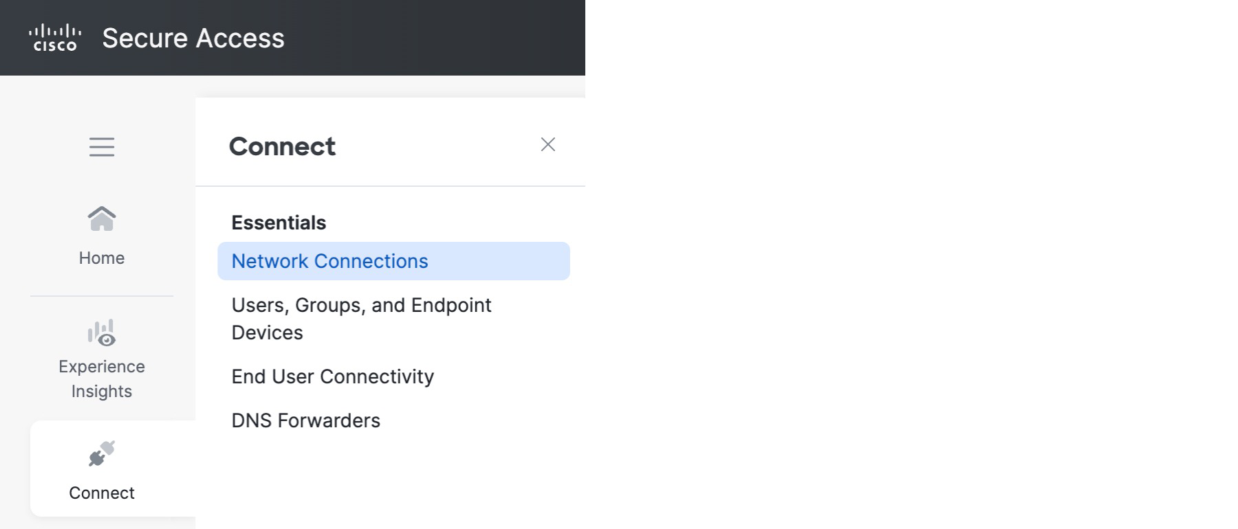
Step 2. Choose Connect > Network Connections.
 |
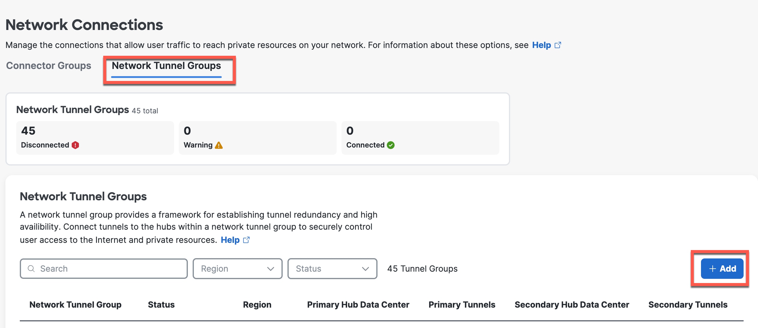
Step 3. Click Network Tunnel Groups and click Add.
 |
Step 4. On the General Settings page, enter the following values.
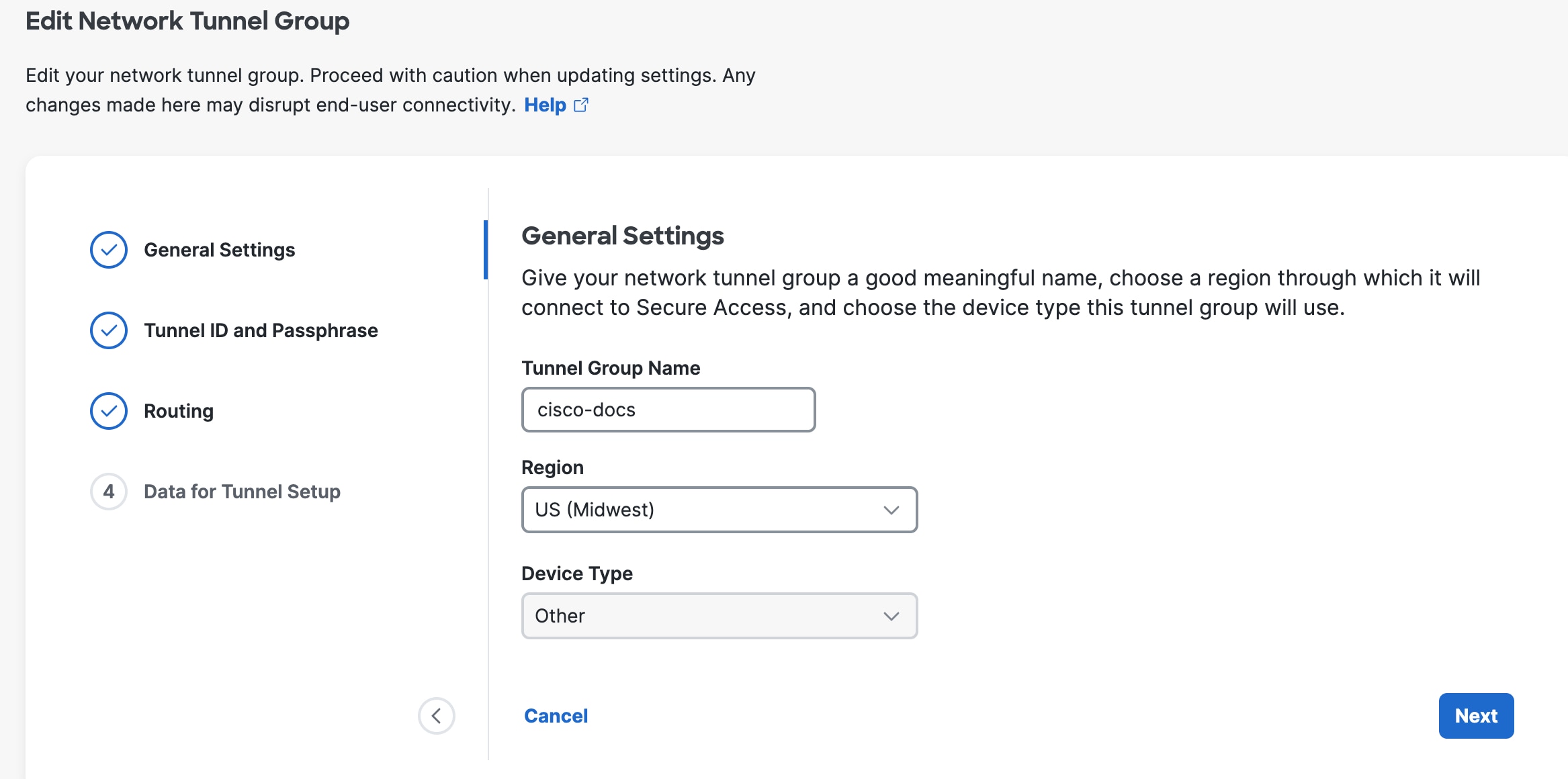
Tunnel Group Name—Enter a meaningful name for the tunnel group.
Region—Select the one closest to your SD-WAN infrastructure.
Device Type — Velocloud.
Step 5. Click Next.
Step 6. On the Tunnel ID and Passphrase page, enter the following values.
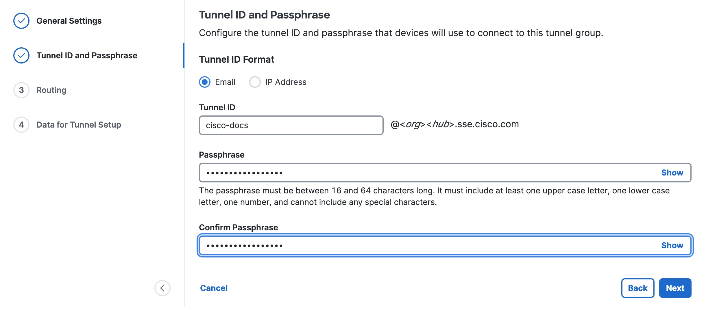 |
Tunnel ID Format is preset to Email.
Secure Access will format it as tunnel_id@org-hub-sse.cisco.com.
Passphrase—Enter a passphrase between 16 and 64 characters in length. The passphrase must contain at least one upper-case letter and one number. The passphrase can’t include any special characters.
Confirm Passphrase—Re-enter your passphrase to confirm.
Step 7. Click Next.
Step 8. On the Routing page, set the following values.
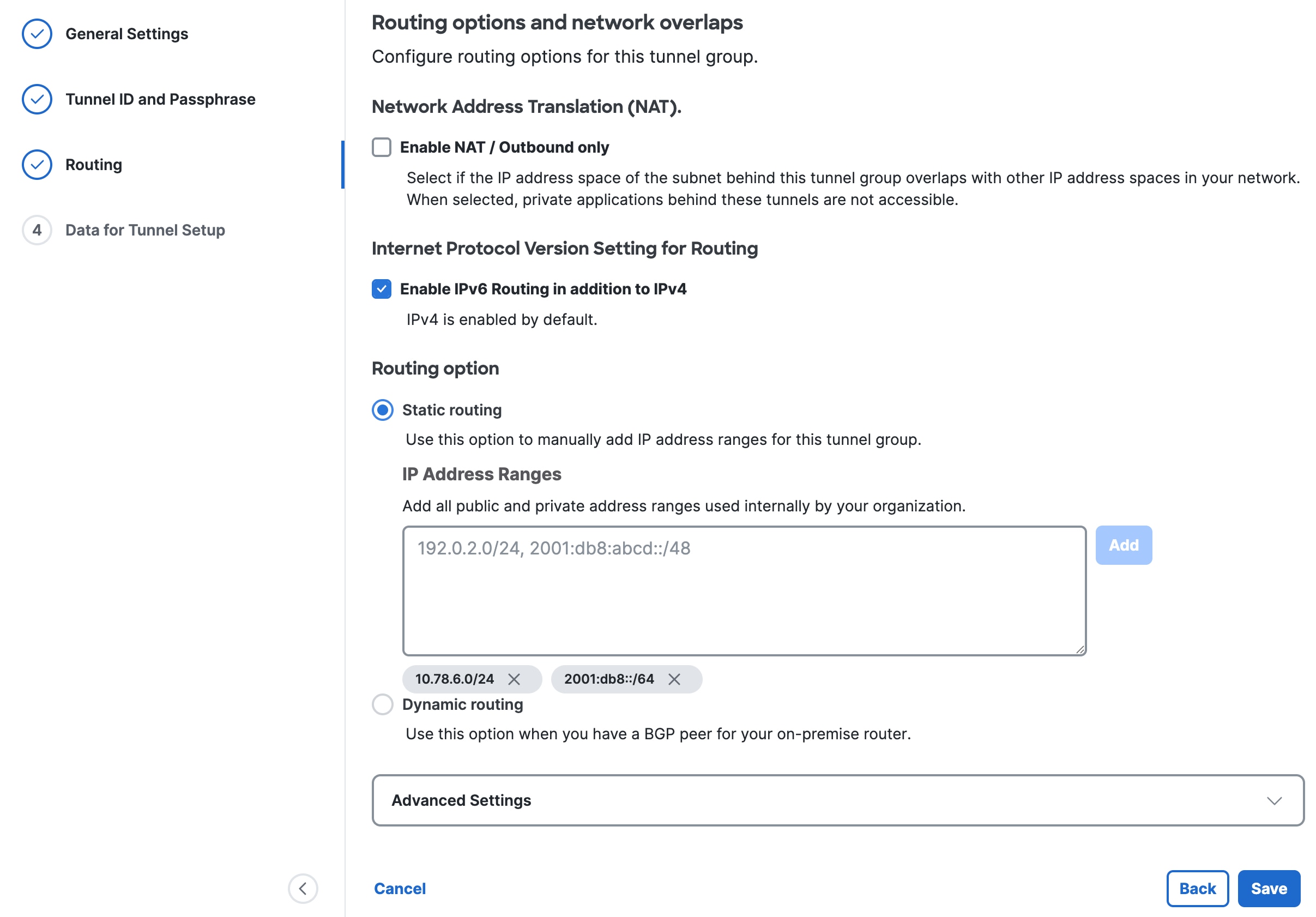 |
(Optional) Network Address Translation (NAT)—To use NAT, check Enable NAT / Outbound only. If you check this option, the routing settings are disabled.
(Optional) Internet Protocol Version Setting for Routing—Check Enable IPv6 Routing in addition to IPv4.
Click a Routing option for this tunnel group:
—Static routing—Manually add IP Address subnets (IPv4 and IPv6) for this tunnel group separated by commas and then click Add. You can click Add multiple times until you add all the subnets you need. Add all public and private address ranges used internally by your organization.
—Dynamic routing—Use this option for BGP. Enter the SD-WAN Device AS Number. If you enabled IPv6 routing, check one or both Enable IPv4 and Enable IPv6. Under Advanced Settings, you can enable other options.
Step 9. Click Save.
Step 10. On the Data for Tunnel Setup page, review the information and click Done.
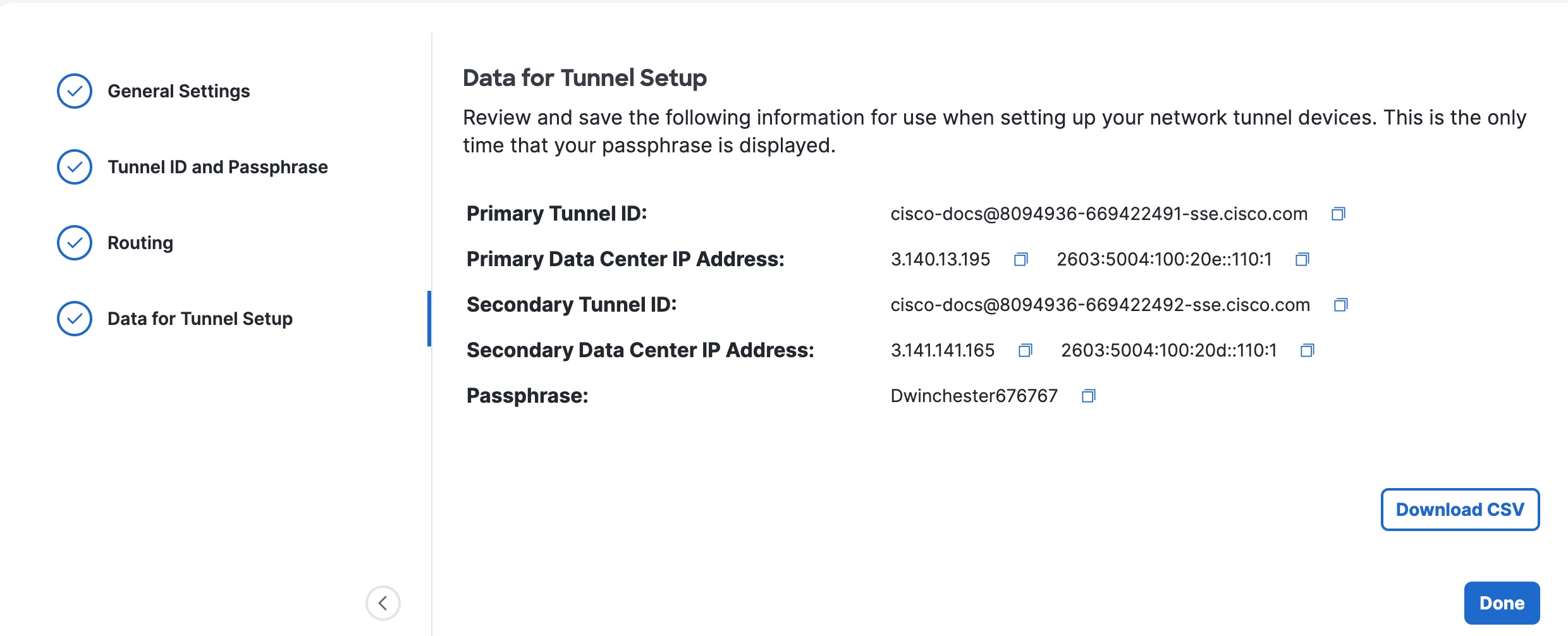 |
This page shows the tunnel ID (the same value for both primary and secondary), data center IP addresses that you should use when you set up the tunnels on your branch devices, and the chosen passphrase. You can view these later by choosing Connect > Network Connections, clicking Network Tunnel Groups, and then choosing View Details for your network tunnel group. You can’t view the passphrase later, so be sure to note the passphrase in a safe place.
Configure VeloCloud Edge Devices
Configure the IPSec tunnel on the VeloCloud edge to enable the redundant connections to Secure Access.
Procedure
Step 1. Log into Arista Edge Cloud Orchestrator.
Step 2. In the SD-WAN service of the Enterprise portal, choose Configure > Network Services.
Step 3. Under Non SD-WAN Destinations, expand Non SD-WAN Destinations via Edge.
Step 4. Click New.
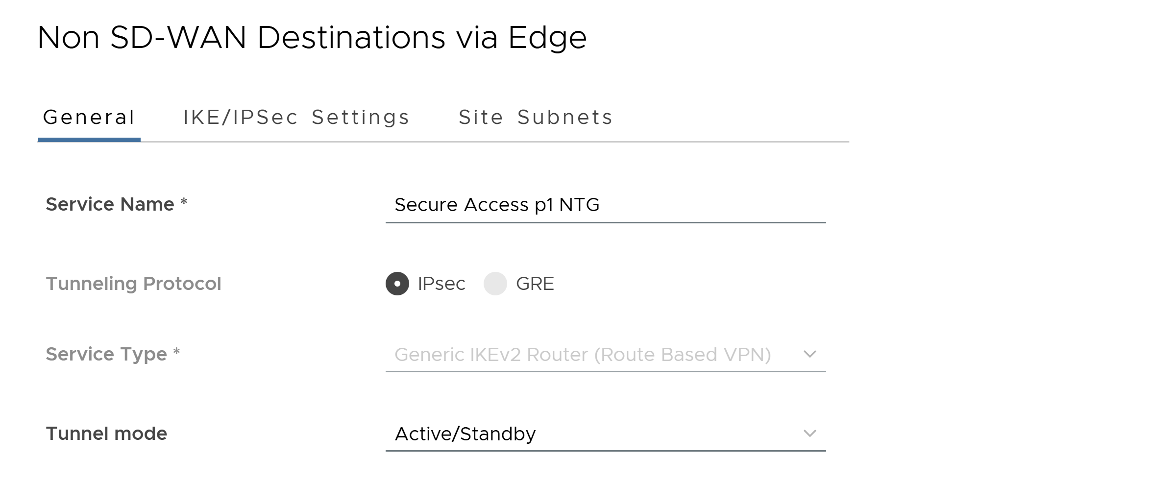
Step 5. Configure the following General tab values.
Table 1. Non SD-WAN Destinations via Edge General values
| Field |
Value |
| Service Name |
Enter a name for the SD-WAN tunnel. |
| Tunneling Protocol |
IPSec |
| Service Type |
Generic IKEv2 Router (Route Based VPN) |
| Tunnel Mode |
Active/Standby |
 |
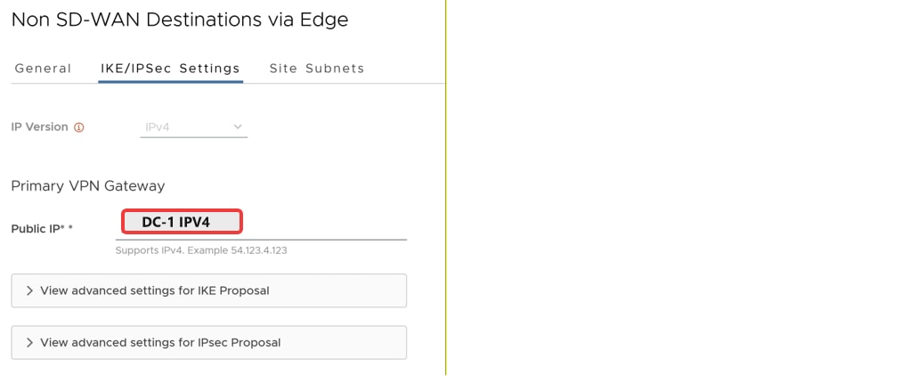
Step 6. Click the IKE/IPSec Settings tab and set the following values.
You can view this tunnel information in Secure Access. Choose Connect > Network Connections, click Network Tunnel Groups, and then choose View Details for your network tunnel group.
Table 2. Non SD-WAN Destinations via Edge IKE/IPSec Settings values
| Field |
Value |
| IP Version |
Choose IPv4 or IPv6. |
| Primary VPN Gateway Public IP |
Specify the Secure Access primary data center IP address. You can view this tunnel information in Secure Access. Choose Connect > Network Connections, click Network Tunnel Groups, and then choose View Details for your network tunnel group. |
 |
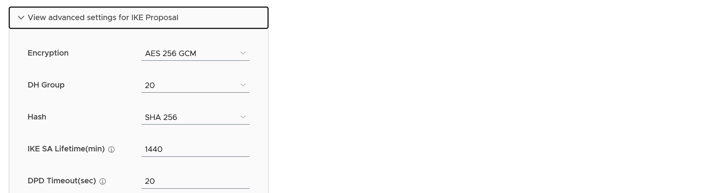
Step 7. Expand View advanced settings for IKE Proposal and set the following values.
Table 3. Advanced Settings for IKE Proposal values
| Field |
Value |
| Encryption |
AES 256 GCM |
| DH Group |
20 |
| Hash |
SHA 256 |
| IKE SA Lifetime(min) |
Accept the default value. |
| DPD Timeout(sec) |
Accept the default value. |
 |
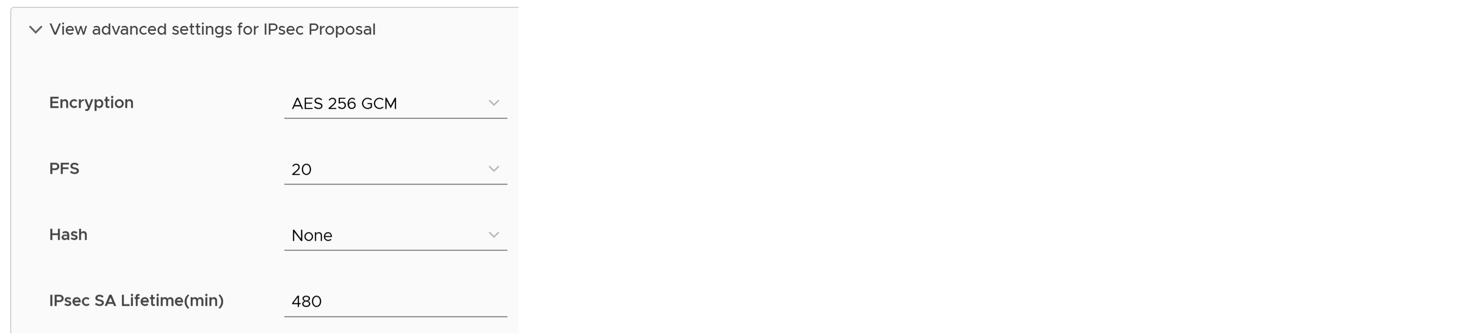
Step 8. Click View advanced settings for IPsec Proposal and set the following values.
Table 4. Advanced Settings for IPSec Proposal values
| Field |
Value |
| Encryption |
AES 256 GCM |
| PFS |
20 |
| Hash |
Accept the default value. |
| IPsec SA Lifetime(min) |
Accept the default value. |
 |
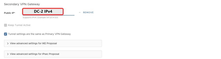
Step 9. Add a Secondary VPN Gateway and set the Public IP to the Secure Access secondary data center IP address.
 |
Step 10. Click the Site Subnets tab and click Add to add subnets reachable via Secure Access.
Step 11. Click Save.
Step 12. Next, choose Configure > Edges to associate the network service with your Edge device.
Step 13. Click on Edge device from the list.
Step 14. Under VPN Services, toggle On Cloud VPN.
Step 15. Under Non SD-WAN Destination via Edge, click Override.
Step 16. Expand Under Non SD-WAN Destination via Edge and click +Add.
Step 17. Under Name, select your Network Service profile created above.
Step 18. On the right side of the row, click on + sign to add tunnel details.
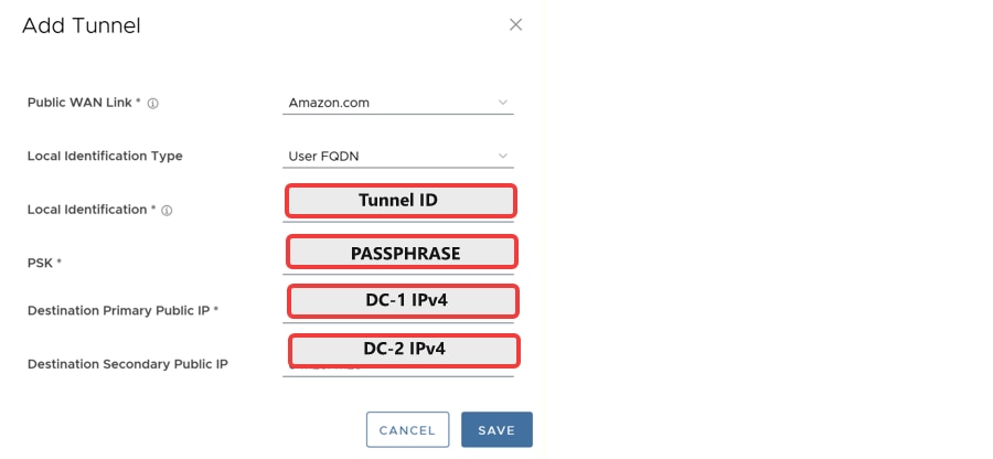
Step 19. Add Tunnel details per below.
| Field |
Value |
| Public WAN Link |
Select the WAN interface by name |
| Local Identification Type |
User FQDN |
| Local Identification |
Enter Primary Tunnel Group ID from Secure Access NTG |
| PSK |
Enter the pre-shared key configured in the Network Tunnel Group in Secure Access |
| Destination Primary Public IP |
Enter Primary Tunnel Hub IP Address from Secure Access NTG |
| Destination Secondary Public IP |
Enter Secondary Tunnel Hub IP Address from Secure Access NTG |
 |
Step 20. Click Save.
Step 21. Click Save Changes.
Step 22. Confirm Action, click Accept.
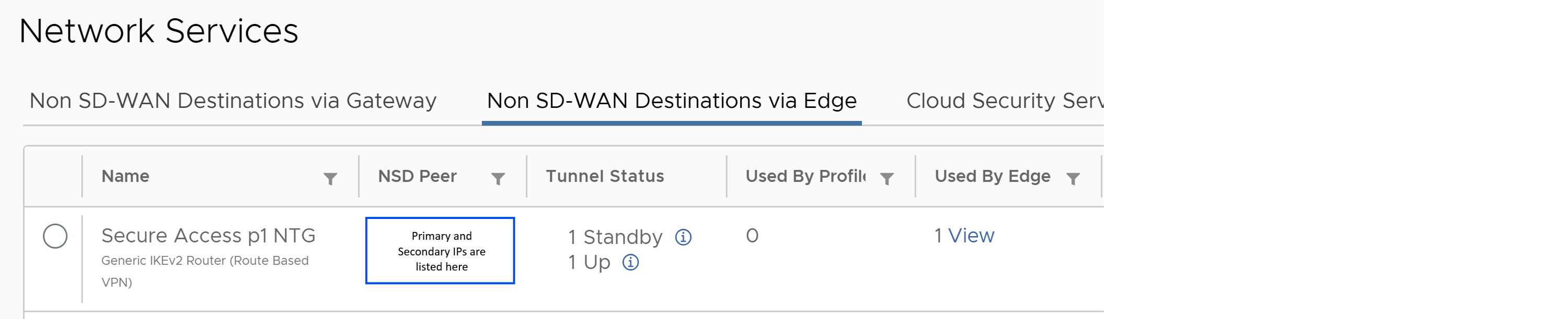
Once the tunnels are established in a few minutes, you can review the status in Monitor > Network Services and click on Non SD-WAN Destinations via Edge tab. Under Tunnel Status, you should see 1 Up and 1 Standby tunnel.
 |
Cisco and the Cisco logo are trademarks or registered trademarks of Cisco and/or its affiliates in the U.S. and other countries. To view a list of Cisco trademarks, go to this URL: www.cisco.com/go/trademarks. Third-party trademarks mentioned are the property of their respective owners. The use of the word partner does not imply a partnership relationship between Cisco and any other company. (1110R)
Any Internet Protocol (IP) addresses and phone numbers used in this document are not intended to be actual addresses and phone numbers. Any examples, command display output, network topology diagrams, and other figures included in the document are shown for illustrative purposes only. Any use of actual IP addresses or phone numbers in illustrative content is unintentional and coincidental.
© 2026 Cisco Systems, Inc. All rights reserved.