Secure Access SD-WAN Integration with HPE Aruba Networking EdgeConnect
Available Languages
Bias-Free Language
The documentation set for this product strives to use bias-free language. For the purposes of this documentation set, bias-free is defined as language that does not imply discrimination based on age, disability, gender, racial identity, ethnic identity, sexual orientation, socioeconomic status, and intersectionality. Exceptions may be present in the documentation due to language that is hardcoded in the user interfaces of the product software, language used based on RFP documentation, or language that is used by a referenced third-party product. Learn more about how Cisco is using Inclusive Language.
- US/Canada 800-553-2447
- Worldwide Support Phone Numbers
- All Tools
 Feedback
 Feedback
About Secure Access SD-WAN Integration with HPE Aruba Networking EdgeConnect
Configure a Secure Access network tunnel group
Configure EdgeConnect for IPSec tunnels
Create the Business Intent Overlay (BIO)
About Secure Access SD-WAN Integration with HPE Aruba Networking EdgeConnect
Integrating HPE Aruba Networking EdgeConnect (formerly Silver Peak) SD-WAN with Secure Access lets you leverage a powerful cloud-native security fabric. By establishing a remote network tunnel, you redirect branch traffic through Cisco’s global security infrastructure, enabling advanced protection for all internet-bound activities, SaaS platforms, and public-facing partner apps.
Whether you are connecting a single branch to one gateway or orchestrating a complex mesh of multiple sites and gateways, Secure Access provides consistent, high-performance security across your entire SD-WAN fabric.
Full Admin account in Secure Access
Configure a Secure Access network tunnel group
Configure Secure Access to connect to the EdgeConnect device.
Procedure
Step 1. Navigate to your Secure Access organization:
https://dashboard.sse.cisco.com
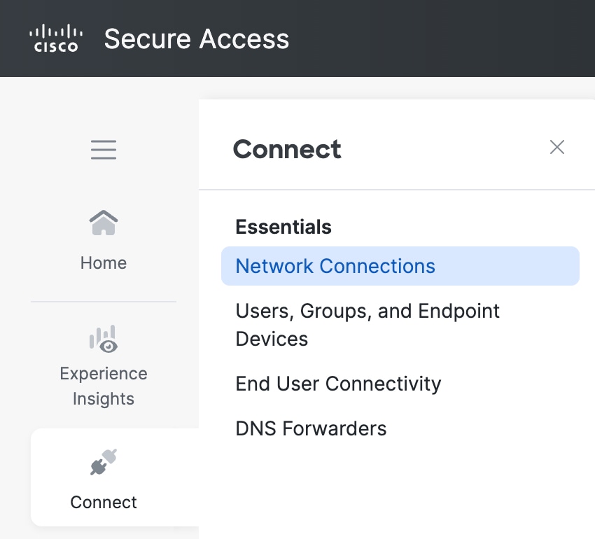
Step 2. Choose Connect > Network Connections.
 |
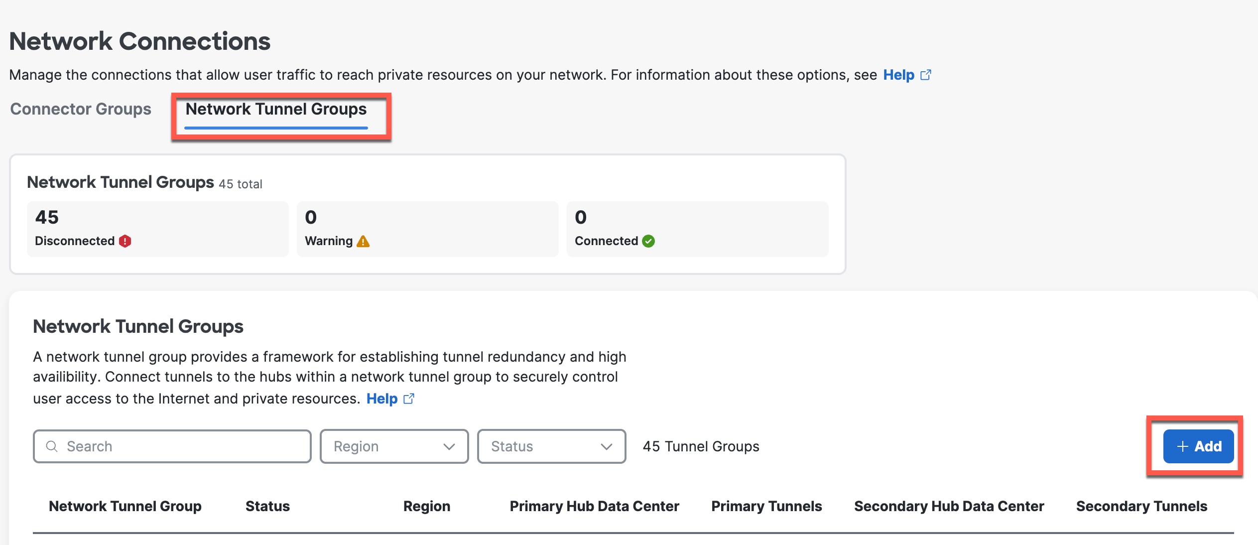
Step 3. Click Network Tunnel Groups and click Add.
 |
Step 4. On the General Settings page, enter the following values.
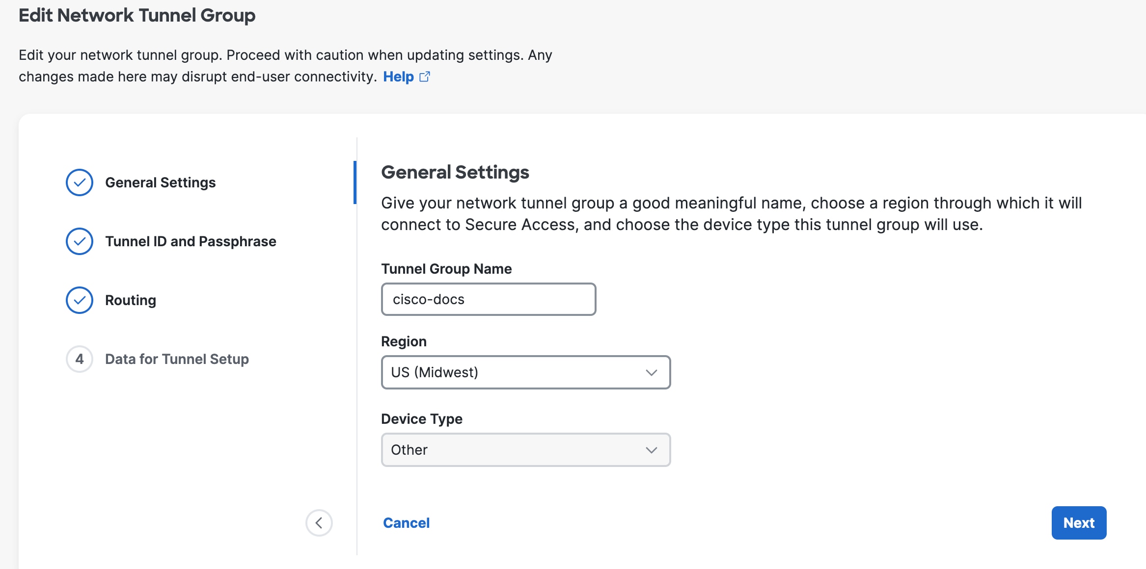 |
Tunnel Group Name—Enter a meaningful name for the tunnel group.
Region—Select the one closest to your SD-WAN infrastructure.
Device Type—Other.
Step 5. Click Next.
Step 6. On the Tunnel ID and Passphrase page, enter the following values.
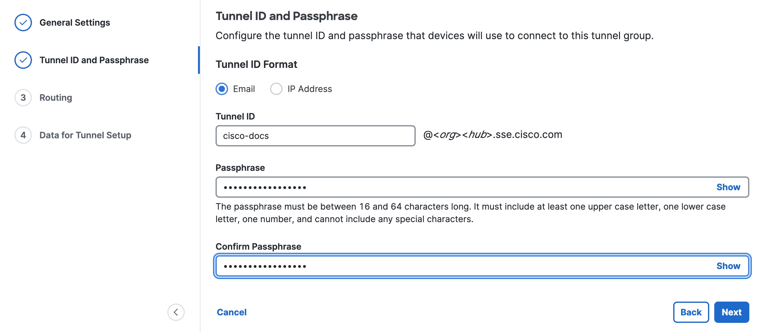 |
Tunnel ID Format—Click Email or IP Address.
For an email, enter the tunnel name you assigned to the tunnel group. Secure Access will format it as tunnel_id@org-hub-sse.cisco.com.
For an IP address, tunnel IDs require both a primary and a secondary IP address. You can specify either IPv4 or IPv6.
Passphrase—Enter a passphrase between 16 and 64 characters in length. The passphrase must contain at least one upper-case letter and one number. The passphrase can’t include any special characters.
Confirm Passphrase—Re-enter your passphrase to confirm.
Step 7. Click Next.
Step 8. On the Routing page, set the following values.
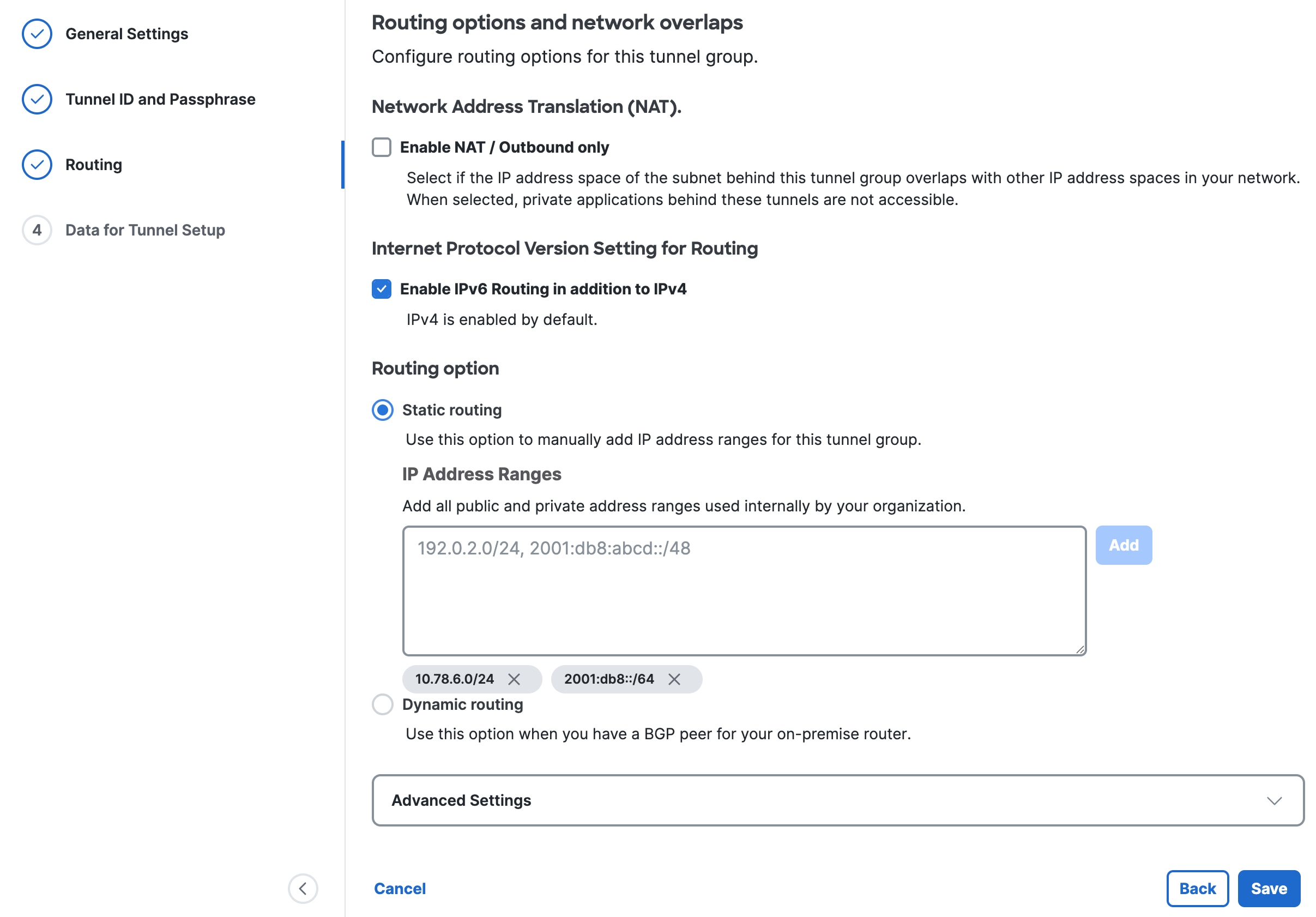 |
(Optional) Network Address Translation (NAT)—To use NAT, check Enable NAT / Outbound only. If you check this option, the routing settings are disabled.
(Optional) Internet Protocol Version Setting for Routing—Check Enable IPv6 Routing in addition to IPv4.
Click a Routing option for this tunnel group:
Static routing—Manually add IP Address subnets (IPv4 and IPv6) for this tunnel group separated by commas and then click Add. You can click Add multiple times until you add all the subnets you need. Add all public and private address ranges used internally by your organization.
Dynamic routing—Use this option for BGP. Enter the SD-WAN Device AS Number. If you enabled IPv6 routing, check one or both Enable IPv4 and Enable IPv6. Under Advanced Settings, you can enable other options.
Step 9. Click Save.
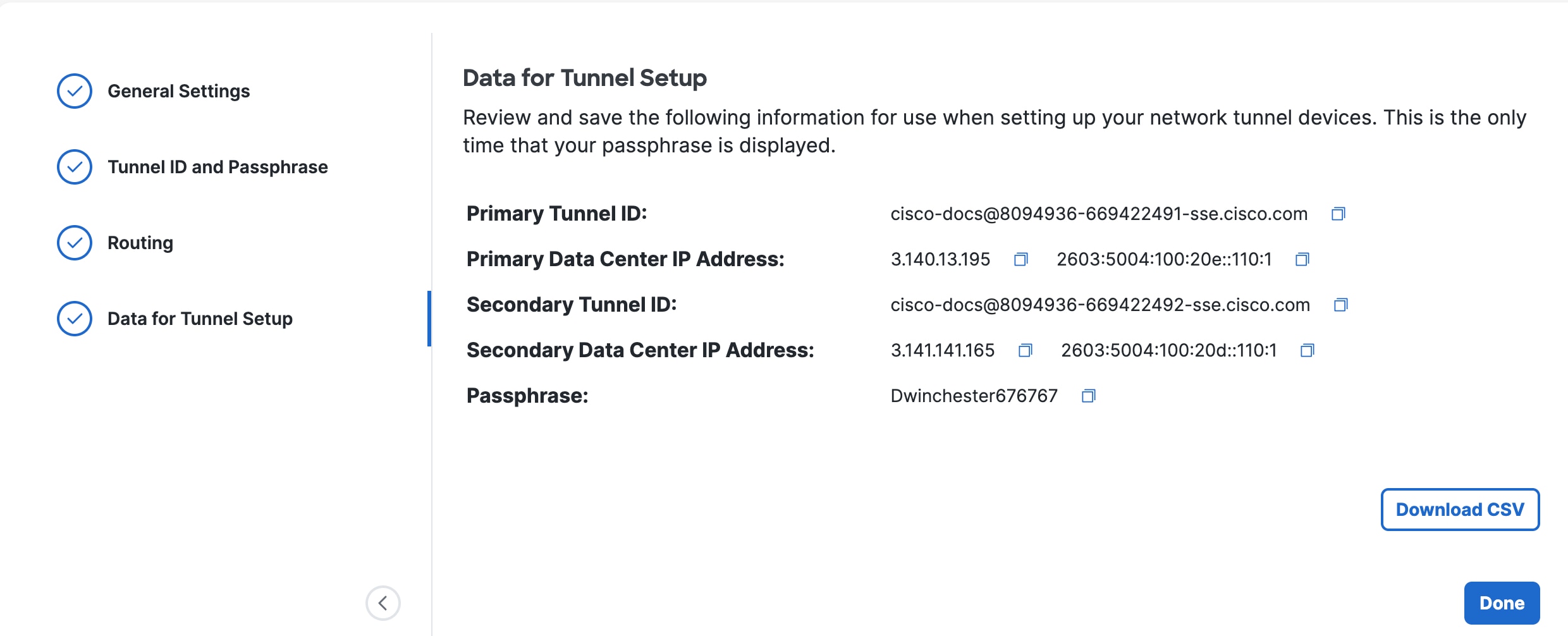
Step 10. On the Data for Tunnel Setup page, review the information and click Done.
 |
Configure EdgeConnect for IPSec tunnels
Configure the IPSec tunnel for EdgeConnect to enable the redundant connections to Secure Access.
Procedure
Step 1. In the HPE Aruba Networking SD-WAN Orchestrator, choose Configuration > Networking > Tunnels > Tunnels.
Step 2. Click the edit icon for the device to which you want to add the tunnel.
Step 3. On the Tunnels dialog box, click Passthrough, and then click Add Tunnel.
Step 4. On the General tab, set the following values:
Table 1. General tab values
| Field |
Value |
| Alias |
Specify the name of the tunnel. |
| Mode |
IPSec |
| IPSec Suite B Preset |
Keep the default option, None. |
| Admin |
Shows whether the tunnel has been set to admin up or down. |
| Local IP / Interface |
Specify the EdgeConnect internet WAN interface IP address. |
| Remote IP / Hostname |
Specify the Secure Access primary data center IP address. You can view this tunnel information in Secure Access. Choose Connect > Network Connections, click Network Tunnel Groups, and then choose View Details for your network tunnel group. |
| NAT |
Keep the default option, none. |
| Peer/Service |
Enter the name of the service. |
| Auto Max BW Enabled |
Check the check box to enable it. |
| Max BW Kbps |
This field auto-populates based on your WAN bandwidth cap. |
Step 5. Click the IKE tab, and set the following values:
Table 2. IKE tab values
| Field |
Value |
| Pre-Shared Key |
Enter the passphrase you set when you added the network tunnel group in Secure Access. |
| Authentication Algorithm |
SHA-256 |
| Encryption Algorithm |
AES-256 |
| Diffie-Hellman Group |
14 |
| Rekey interval/lifetime |
Keep the default value (360 minutes). |
| Dead Peer Detection |
Delay time: 10 Retry count: 3 |
| Local IKE Identifier |
Enter the Secure Access primary tunnel group ID. You can view this tunnel information in Secure Access. Choose Connect > Network Connections, click Network Tunnel Groups, and then choose View Details for your network tunnel group. |
| Remote IKE Identifier |
Enter the Secure Access secondary tunnel group ID. You can view this tunnel information in Secure Access. Choose Connect > Network Connections, click Network Tunnel Groups, and then choose View Details for your network tunnel group. |
| Phase 1 Mode |
It is set to Aggressive by default and cannot be changed. |
| IKE Version |
IKEv2 |
Step 6. Click the IPSec tab, and set the following values:
Table 3. IPSec tab values
| Field |
Value |
| Authentication algorithm |
SHA-1 |
| Encryption algorithm |
Auto |
| IPsec anti-replay window |
Disable |
| Rekey interval/lifetime |
Accept the default value. |
| Perfect forward secrecy group |
Accept the default value. |
Step 7. Click Save.
Create the Business Intent Overlay (BIO)
Use the Business Intent Overlays (BIOs) tab to create separate, logical networks that are individually customized to your applications and requirements within your network.
Procedure
Step 1. In the HPE Aruba Networking SD-WAN Orchestrator, choose Configuration > Overlays & Security > Business Intent Overlays.
Step 2. Select the BIO policy that has the Breakout Traffic to Internet & Cloud Services settings to direct traffic to Secure Access.
Step 3. In the Match field, select Overlay ACL.
Step 4. Click the edit icon next to the ACL field.
Step 5. Click Add Rule.
Step 6. Click Match Criteria, select Others, and then click Save.
Step 7. Ensure traffic permission is set to Permit and click Apply
Create an access list for interesting traffic
Procedure
Step 1. In the HPE Aruba Networking SD-WAN Orchestrator, choose Configuration > Templates & Policies > ACLs > Access Lists, and then and click Add.
Step 2. Click Add Rule, click Match Criteria, and then select Other.
Step 3. Click Save.
Step 4. Confirm that traffic permission is set to Permit and click Apply.
Create a Route Map
Procedure
Step 1. In the HPE Aruba Networking SD-WAN Orchestrator, choose Configuration > Templates & Policies > Policies > Route Policies and click Add Map.
Step 2. Click Add Rule and then click Match Criteria.
Step 3. Select ACL and from the drop-down list to choose the ACL created in the previous step.
Step 4. Click Set Actions and add the following:
Destination Type—Passthrough Tunnel
Destination—tunnel to Umbrella
Fallback—pass-through
Step 5. Click Save, and then click Apply.
Cisco and the Cisco logo are trademarks or registered trademarks of Cisco and/or its affiliates in the U.S. and other countries. To view a list of Cisco trademarks, go to this URL: www.cisco.com/go/trademarks. Third-party trademarks mentioned are the property of their respective owners. The use of the word partner does not imply a partnership relationship between Cisco and any other company. (1110R)
Any Internet Protocol (IP) addresses and phone numbers used in this document are not intended to be actual addresses and phone numbers. Any examples, command display output, network topology diagrams, and other figures included in the document are shown for illustrative purposes only. Any use of actual IP addresses or phone numbers in illustrative content is unintentional and coincidental.
© 2026 Cisco Systems, Inc. All rights reserved.