Managing the Secure Firewall Threat Defense Virtual with the Cloud-Delivered Firewall Management Center

This chapter describes how to deploy a Firewall Threat Defense Virtual device managed with the Cloud-Delivered Firewall Management Center.

Onboarding Overview

Cloud-Delivered Firewall Management Center is supported on Threat Defense Virtual devices running Secure Firewall versions 7.0.3,7.2.0, and later. To see all supported versions and product compatibility, see Secure Firewall Threat Defense Compatibility Guide for more information.

There are three different types of scenarios in which you onboard a threat defense virtual device to the cloud-delivered Firewall Management Center:

  • Onboard a new threat defense virtual device

  • Onboard a threat defense virtual device that is currently managed by the device manager


    Note


    If you onboard a device manager-managed device to the Cloud-Delivered Firewall Management Center, you can no longer manage the device with the device manager.


  • Onboard a threat defense virtual device that is currently managed by an on-prem management center. See Migrate Secure Firewall Threat Defense to Cloud for more information.


    Note


    The following scenarios occur when you either move or migrate a device to the Cloud-Delivered Firewall Management Center:

    • If you delete a device from an on-prem management center or Secure Firewall Threat Defense device manager to onboard to the Cloud-Delivered Firewall Management Center, the change of managers wipes any policies configured through the on-prem management center.

    • If you migrate a device from an on-prem management center to the Cloud-Delivered Firewall Management Center, the device retains the majority of your previously configured policies.

    If you do not know if your device is already managed by an alternative manager, use the show managers command on the CLI.


This guide provides information on the basics of managing threat Defense Virtual using Cloud-Delivered Firewall Management Center. For more detailed information on Security Cloud Control, see Cisco Security Cloud Control.

Prerequisites to Onboard a Device to Cloud-Delivered Firewall Management Center

Onboard Limitations and Requirements

Be aware of the following limitations when onboarding a device to the cloud-delivered Firewall Management Center:

  • Devices must be running version 7.0.3, or version 7.2 and later. We strongly recommend version 7.2 or later.

  • You can migrate an HA pair that is managed by an On-Premises Firewall Management Center by following the Migrate FTD to Cloud-Delivered Firewall Management Center process. Confirm both peers are in a healthy state prior to migrating.

  • Only devices that are configured for local management and are managed by a Firewall Device Manager can be onboarded with the serial number and zero-touch provisioning methods.

  • If the device is managed by an on-premises management center, you can either onboard the device to cloud-delivered Firewall Management Center or migrate the device. Migrating retains any existing policies and objects, whereas onboarding the device removes most policies and all objects. See Migrate FTD to Cloud-Delivered Firewall Management Center for more information.

  • If your device is currently managed by a Firewall Device Manager, unregister all your smart licenses before you onboard the device. Even if you switch device management, the Cisco Smart Software Manager will retain the smart licenses.

  • If you have previously onboarded a device that was managed by a Firewall Device Manager and deleted the device from Security Cloud Control with the intention of re-onboarding for cloud management, you must register the Firewall Device Manager to the Security Services Exchange cloud after deleting the device. See the "Access Security Services Exchange" chapter in the Firepower and Cisco SecureX Threat Response Integration Guide.


Tip


Onboarding a device to the cloud-delivered Firewall Management Center removes any policies and most objects configured through the previous manager. If your device is currently managed by an on-premises management center, it is possible to migrate the device and retain your policies and objects. See Migrate FTD to Cloud-Delivered Firewall Management Center for more information.


Network Requirements

Before you onboard a device, ensure the following ports have external and outbound access. Confirm the following ports on the device are allowed. If communication ports are blocked behind a firewall, onboarding the device may fail.


Note


You cannot configure these ports in the Security Cloud Control UI. You must enable these ports through the device's SSH.


Table 1. Device Port Requirements

Port

Protocol / Feature

Details

443/tcp

HTTPS

Send and receive data from the internet.

443

HTTPS

Communicate with the AMP cloud (public or private)

8305/tcp

Appliance communications

Securely communicate between appliances in a deployment.

Management and Data Interfaces

Make sure your device is correctly configured with either a management or data interface.

Create a Security Cloud Control Tenant

You can provision a new Security Cloud Control tenant to onboard and manage your devices. If you use an On-Premises Firewall Management Center Version 7.2 and later, and want to integrate it with the Cisco Security Cloud, you can also create a Security Cloud Control tenant as part of the integration workflow.

Procedure

  1. Go to https://us.manage.security.cisco.com/provision.

  2. Select the region where you want to provision your Security Cloud Control tenant and click Sign Up.

  3. On the Security Cloud Sign On page, provide your credentials.

  4. If you do not have a Security Cloud Sign On account and want to create one, click Sign up now.

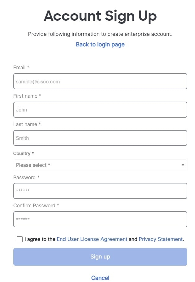
    1. Provide the information to create an account.

      Here are some tips:

      • Email: Enter the email address that you will eventually use to log in to Security Cloud Control.

      • Password: Enter a strong password.

    2. Click Sign up. Cisco sends you a verification email to the address you registered with.

    3. Open the email and click Activate account both on the mail and the Security Cloud Sign On page.

    4. Configure multifactor authentication using Duo on a device of your choice and click Log in with Duo and Finish.


      Note


      We recommend installing the Duo Security app on a mobile phone. Review Duo Guide to Two Factor Authentication: Enrollment Guide if you have questions about installing Duo.


  5. Provide a name for your tenant and click Create new account.
  6. A new Security Cloud Control tenant is created in the region that you have chosen; you will also receive an email about your Security Cloud Control tenant being created, with the details. If you are associated with multiple Security Cloud Control tenants already, on the Choose a tenant page, select the tenant you just created to log in to it. If you have created a new Security Cloud Control tenant for the first time, you get logged into your tenant directly.

Onboard a Device with a CLI Registration Key

Use the procedure below to onboard a device for cloud-delivered Firewall Management Center with a CLI registration key.


Note


If your device is currently managed by an on-premises management center, onboarding the device will fail. You can either delete the device from the on-premises management center and onboard as a fresh, new device with no policies or objects, or you can migrate the device and retain the existing policies and objects. See Migrate FTD to Cloud-Delivered Firewall Managmenet Center for more information.


Before you begin

Before you onboard a device, be sure to complete the following tasks:

  • Cloud-Delivered Firewall Management Center is enabled for your tenant.

  • Device must be running version 7.0.3, or 7.2.0 and later.

Procedure


Step 1

Log in to Security Cloud Control.

Step 2

In the left pane, click .

Step 3

In the top-right corner, click Onboard ().

Step 4

Click the FTD tile.

Step 5

Under Management Mode, ensure you select FTD. By selecting FTD under Management Mode, you will not be able to manage the device using the previous management platform. All existing policy configurations except for interface configurations will be reset. You must re-configure policies after you onboard the device.

Step 6

Select Use CLI Registration Key as the onboarding method.

Step 7

Enter the device name in the Device Name field and click Next.

Step 8

In the Policy Assignment step, use the drop-down menu to select an access control policy to deploy once the device is onboarded. If you have no policies configured, select the Default Access Control Policy.

Step 9

Specify whether the device you are onboarding is a physical or virtual device. If you are onboarding a virtual device, you must select the device's performance tier from the drop-down menu.

Step 10

Select the subscription licenses you want to apply to the device. Click Next.

Step 11

Security Cloud Control generates a command with the registration key. Connect to the device you are onboarding using SSH. Log in as "admin" or a user with equivalent admin privileges and paste the entire registration key as is into the device's CLI.

Note: For Firepower 1000, Firepower 2100, ISA 3000, and Firewall Threat Defense Virtual devices, open an SSH connection to the device and log in as admin. Copy the entire registration command and paste it into the device's CLI interface at the prompt. In the CLI, enter Y to complete the registration. If your device was previously managed by Firewall Device Manager, enter Yes to confirm the submission.

Step 12

Click Next in the Security Cloud Control onboarding wizard.

Step 13

(Optional) Add labels to your device to help sort and filter the Security Devices page. Enter a label and select the blue plus button. Labels are applied to the device after it's onboarded to Security Cloud Control.


What to do next

Once the device is synchronized, select the device you just onboarded from the Security Devices page and select any of the options listed under the Device Management pane located to the right. We strongly recommend the following actions:
  • If you did not already, create a custom access control policy to customize the security for your environment. See Access Control Overview in Managing Firewall Threat Defense with Cloud-Delivered Firewall Management Center in Firewall in Security Cloud Control for more information.

  • Enable Cisco Security Analytics and Logging (SAL) to view events in the Security Cloud Control dashboard or register the device to an Secure Firewall Management Center for security analytics. See Cisco Security Analytics and Logging in Managing Firewall Threat Defense with Cloud-Delivered Firewall Management Center in Firewall in Security Cloud Control for more information.

Configure a Basic Security Policy

This section describes how to configure a basic security policy with the following settings:

  • Inside and outside interfaces—Assign a static IP address to the inside interface, and use DHCP for the outside interface.

  • DHCP server—Use a DHCP server on the inside interface for clients.

  • Default route—Add a default route through the outside interface.

  • NAT—Use interface PAT on the outside interface.

  • Access control—Allow traffic from inside to outside.

Procedure


Step 1

Configure Interfaces

Step 2

Configure the DHCP Server

Step 3

Add the Default Route

Step 4

Configure NAT

Step 5

Configure Access Control

Step 6

Deploy the Configuration


Configure Interfaces

Enable the Firewall Threat Defense Virtual interfaces, assign them to security zones, and set the IP addresses. Typically, you must configure at least a minimum of two interfaces to have a system that passes meaningful traffic. Normally, you would have an outside interface that faces the upstream router or internet, and one or more inside interfaces for your organization’s networks. Some of these interfaces might be “demilitarized zones” (DMZs), where you place publically-accessible assets such as your web server.

A typical edge-routing situation is to obtain the outside interface address through DHCP from your ISP, while you define static addresses on the inside interfaces.

The following example configures a routed mode inside interface with a static address and a routed mode outside interface using DHCP.

Procedure


Step 1

Choose Devices > Device Management, and click the Edit (edit icon) for the device.

Step 2

Click Interfaces.

Step 3

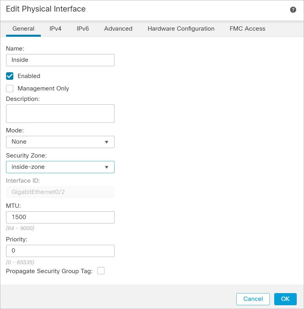
Click the Edit (edit icon) for the interface that you want to use for inside.

The General tab appears.

  1. Enter a Name up to 48 characters in length.

    For example, name the interface inside.

  2. Check the Enabled check box.

  3. Leave the Mode set to None.

  4. From the Security Zone drop-down list, choose an existing inside security zone or add a new one by clicking New.

    For example, add a zone called inside_zone. Each interface must be assigned to a security zone and/or interface group. An interface can belong to only one security zone, but can also belong to multiple interface groups. You apply your security policy based on zones or groups. For example, you can assign the inside interface to the inside zone; and the outside interface to the outside zone. Then you can configure your access control policy to enable traffic to go from inside to outside, but not from outside to inside. Most policies only support security zones; you can use zones or interface groups in NAT policies, prefilter policies, and QoS policies.

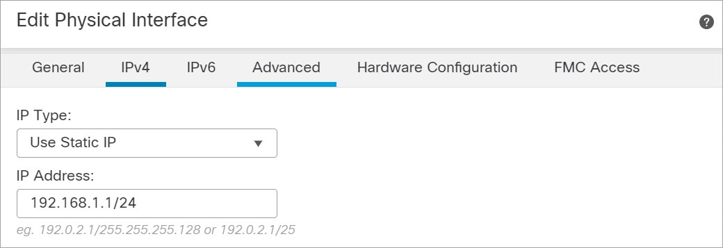
  5. Click the IPv4 and/or IPv6 tab.

    • IPv4—Choose Use Static IP from the drop-down list, and enter an IP address and subnet mask in slash notation or DHCP option .

      For example, enter 192.168.1.1/24

    • IPv6—Check the Autoconfiguration check box for stateless auto configuration and also for IPv6 DHCP or static configuration to enable the interface.

  6. Click OK.

Step 4

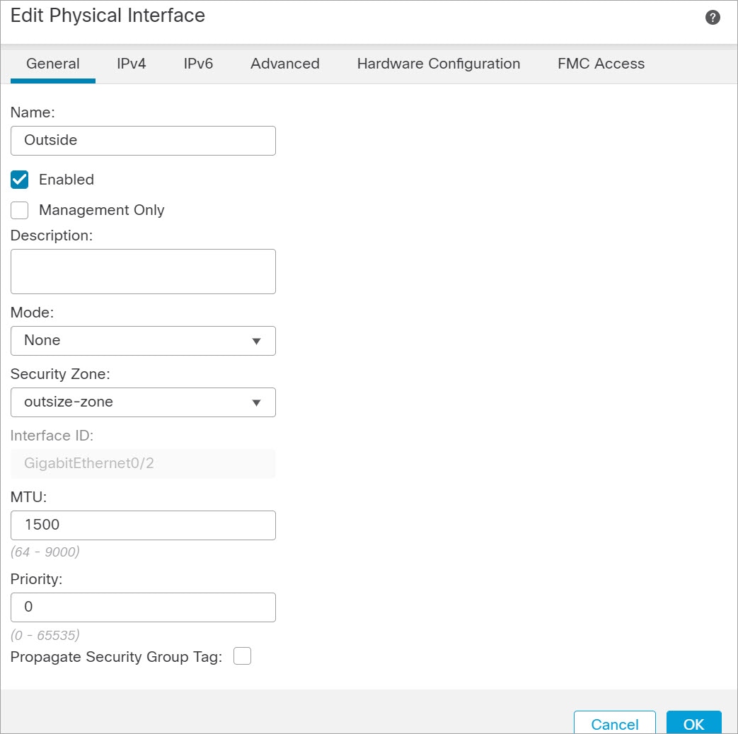
Click the Edit (edit icon) for the interface that you want to use for outside.

The General tab appears.

  1. Enter a Name up to 48 characters in length.

    For example, name the interface outside.

  2. Check the Enabled check box.

  3. Leave the Mode set to None.

  4. From the Security Zone drop-down list, choose an existing outside security zone or add a new one by clicking New.

    For example, add a zone called outside_zone.

  5. Click the IPv4 and/or IPv6 tab.

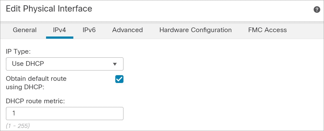
    • IPv4—Choose Use DHCP, and configure the following optional parameters:

      • Obtain default route using DHCP—Obtains the default route from the DHCP server.

      • DHCP route metric—Assigns an administrative distance to the learned route, between 1 and 255. The default administrative distance for the learned routes is 1.

    • IPv6—Check the Autoconfiguration check box for stateless auto configuration.

  6. Click OK.

Step 5

Click Save.


Configure the DHCP Server


Note


Skip this procedure if you are deploying to a public cloud environment such as AWS, Azure, GCP, OCI.


Enable the DHCP server if you want clients to use DHCP to obtain IP addresses from the Firewall Threat Defense Virtual.

Procedure


Step 1

Choose Devices > Device Management, and click the Edit (edit icon) for the device.

Step 2

Choose DHCP > DHCP Server.

Step 3

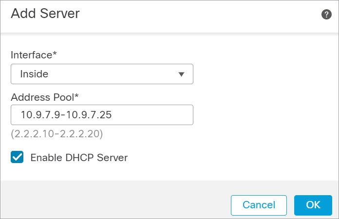
On the Server page, click Add, and configure the following options:

  • Interface—Choose the interface from the drop-down list.

  • Address Pool—Set the range of IP addresses from lowest to highest that are used by the DHCP server. The range of IP addresses must be on the same subnet as the selected interface and cannot include the IP address of the interface itself.

  • Enable DHCP Server—Enable the DHCP server on the selected interface.

Step 4

Click OK.

Step 5

Click Save.


Add the Default Route

The default route normally points to the upstream router reachable from the outside interface. If you use DHCP for the outside interface, your device might have already received a default route. If you need to manually add the route, complete this procedure. If you received a default route from the DHCP server, it will show in the IPv4 Routes or IPv6 Routes table on the Devices > Device Management > Routing > Static Route page.

Procedure


Step 1

Choose Devices > Device Management, and click the Edit (edit icon) for the device.

Step 2

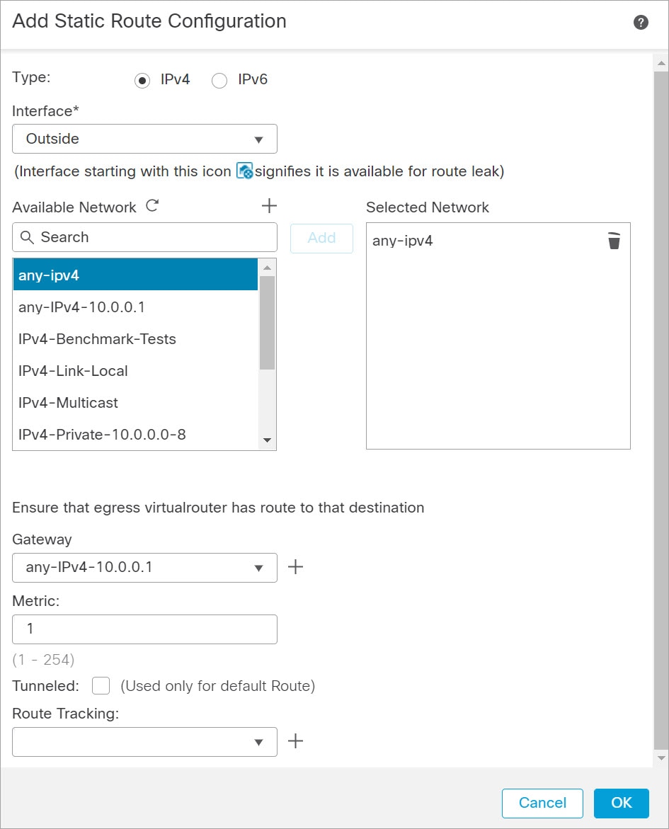
Choose Routing > Static Route, click Add Route, and set the following:

  • Type—Click the IPv4 or IPv6 radio button depending on the type of static route that you are adding.

  • Interface—Choose the egress interface; typically the outside interface.

  • Available Network—Choose any-ipv4 for an IPv4 default route, or any-ipv6 for an IPv6 default route.

  • Gateway or IPv6 Gateway—Enter or choose the gateway router that is the next hop for this route. You can provide an IP address or a Networks/Hosts object.

  • Metric—Enter the number of hops to the destination network. Valid values range from 1 to 255; the default value is 1.

Step 3

Click OK.

The route is added to the static route table.

Step 4

Click Save.


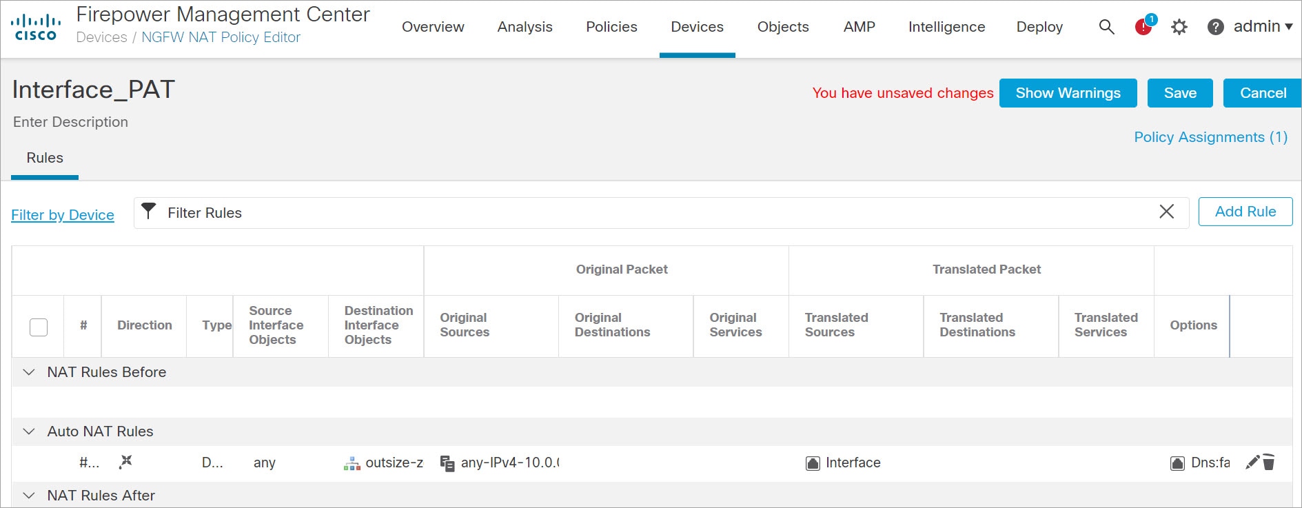
Configure NAT

A typical NAT rule converts internal addresses to a port on the outside interface IP address. This type of NAT rule is called interface Port Address Translation (PAT).

Procedure


Step 1

Choose Devices > NAT, and click New Policy > Threat Defense NAT.

Step 2

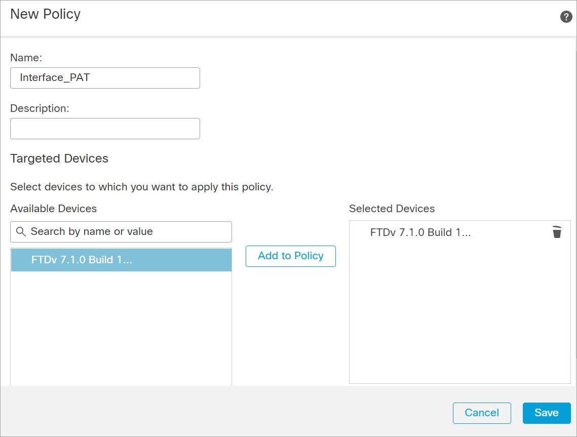
Name the policy, select the device(s) that you want to use the policy, and click Save.

The policy is added the Firewall Management Center. You still have to add rules to the policy.

Step 3

Click Add Rule.

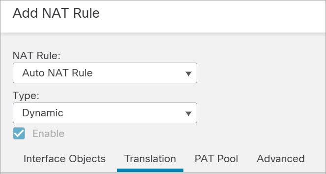
The Add NAT Rule dialog box appears.

Step 4

Configure the basic rule options:

  • NAT Rule—Choose Auto NAT Rule.

  • Type—Choose Dynamic.

Step 5

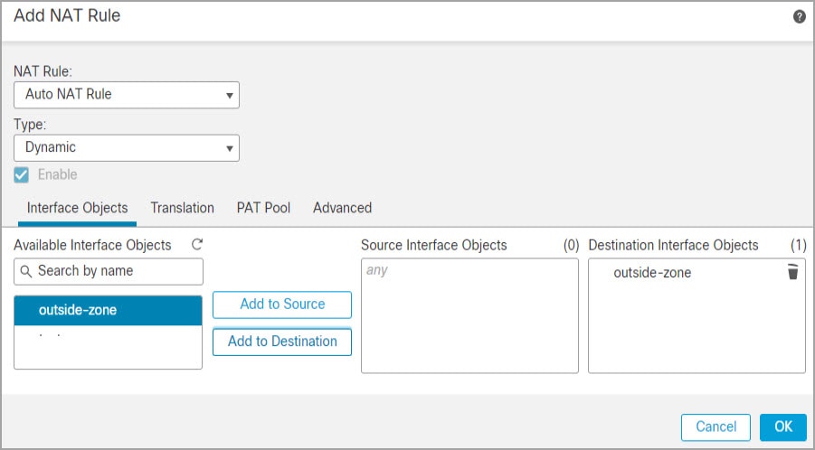
On the Interface Objects page, add the outside zone from the Available Interface Objects area to the Destination Interface Objects area.

Step 6

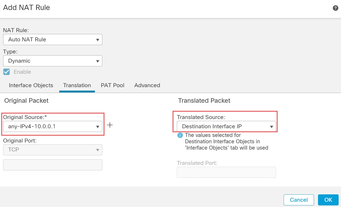
On the Translation page, configure the following options:

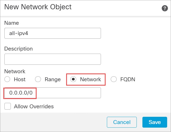
  • Original Source—Click the Add (add icon) to add a network object for all IPv4 traffic (0.0.0.0/0).

    Note


    You cannot use the system-defined any-ipv4 object, because Auto NAT rules add NAT as part of the object definition, and you cannot edit system-defined objects.

    Similarly, you can create the NAT policy with a default host network [::/0] for all IPv6 traffic.

  • Translated Source—Choose Destination Interface IP.

Step 7

Click Save to add the rule.

The rule is saved to the Rules table.

Step 8

Click Save on the NAT page to save your changes.


Configure Access Control

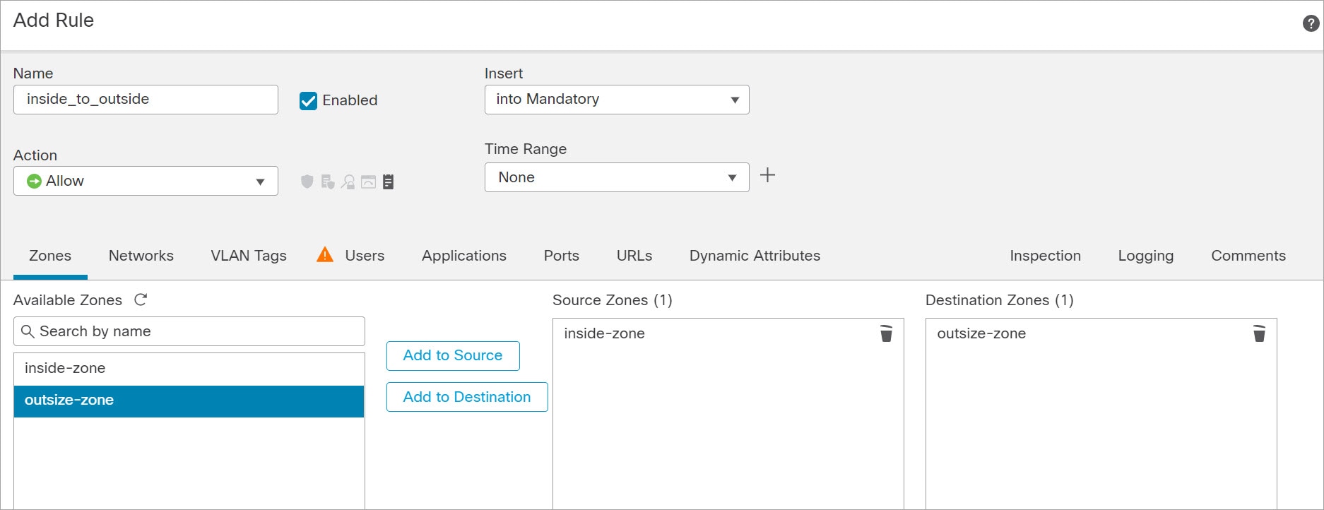
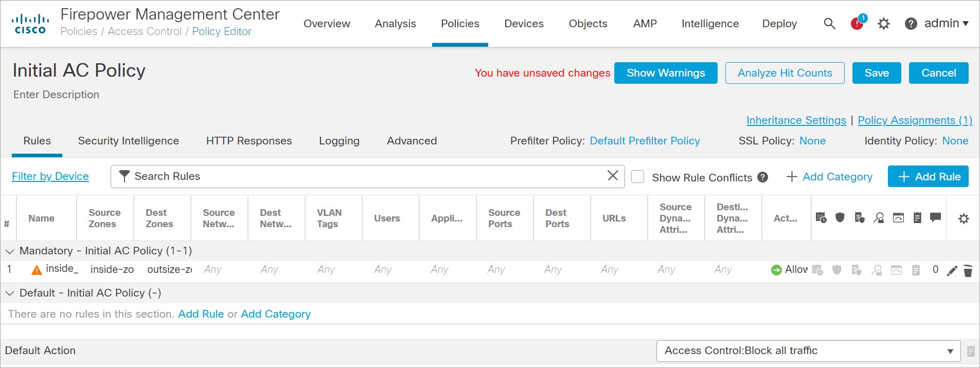
If you created a basic Block all traffic access control policy when you registered the Firewall Threat Defense Virtual with the Firewall Management Center, then you need to add rules to the policy to allow traffic through the device. The following procedure adds a rule to allow traffic from the inside zone to the outside zone. If you have other zones, be sure to add rules allowing traffic to the appropriate networks.

See the Firewall Management Center Configuration Guide configuration guide to configure more advanced security settings and rules.

Procedure


Step 1

Choose Policy > Access Policy > Access Policy, and click the Edit (edit icon) for the access control policy assigned to the Firewall Threat Defense.

Step 2

Click Add Rule, and set the following parameters:

  • Name—Name this rule, for example, inside_to_outside.

  • Source Zones—Select the inside zone from Available Zones, and click Add to Source.

  • Destination Zones—Select the outside zone from Available Zones, and click Add to Destination.

Leave the other settings as is.

Step 3

Click Add.

The rule is added to the Rules table.

Step 4

Click Save.


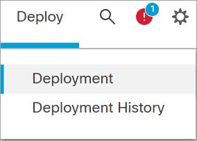
Deploy the Configuration

Deploy the configuration changes to the Firewall Threat Defense Virtual; none of your changes are active on the device until you deploy them.

Procedure


Step 1

Click Deploy in the upper right.

Step 2

Select the device in the Deploy Policies dialog box, then click Deploy.

Step 3

Ensure that the deployment succeeds. Click the icon to the right of the Deploy button in the menu bar to see status for deployments.