Deploy the Firewall Threat Defense Virtual on Azure Virtual WAN

This chapter explains how to deploy Firewall Threat Defense Virtual instances using a solution template on Azure Virtual WAN.

Introduction to Threat Defense Virtual in Azure Virtual WAN

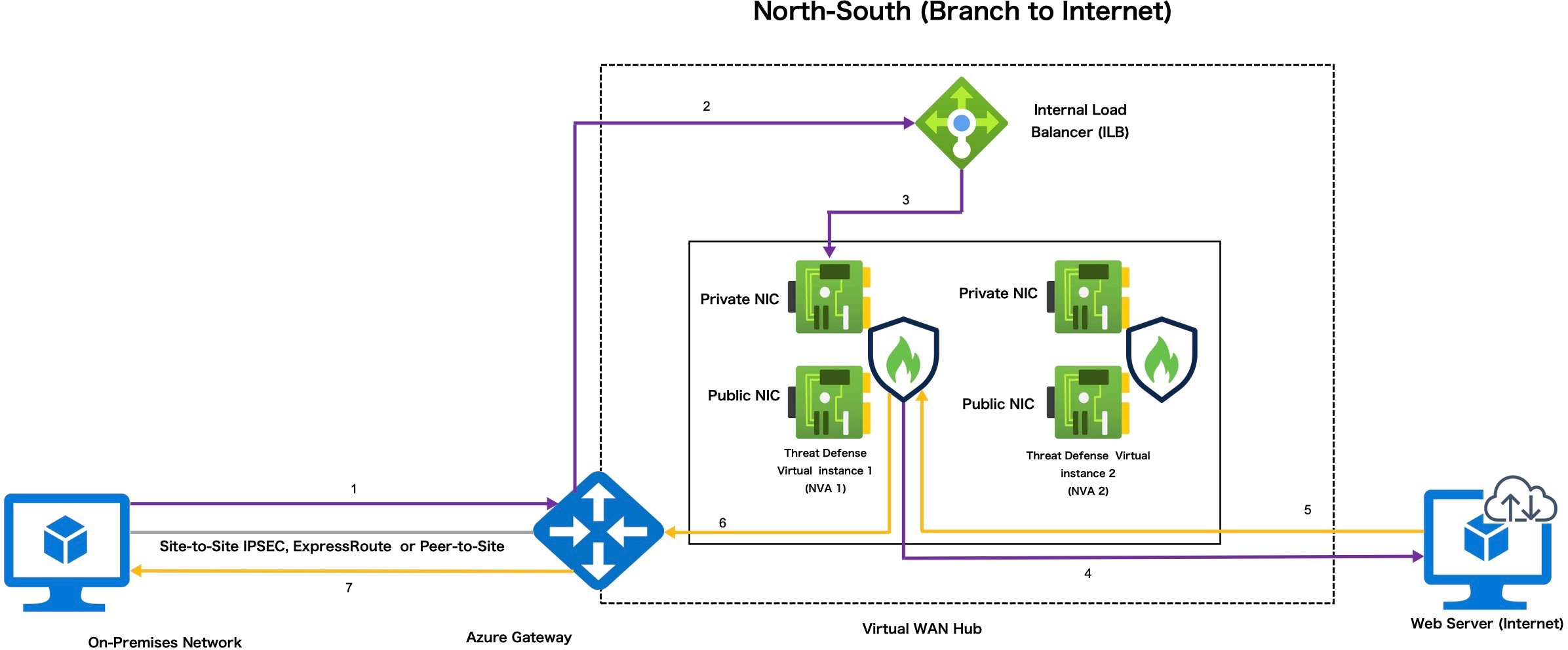
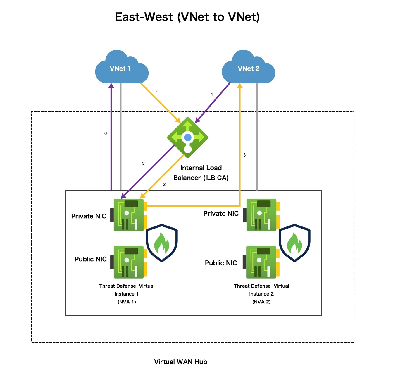
Microsoft Azure Virtual WAN employs a 'hub-and-spoke' architecture to manage traffic across various virtual networks and branch locations. Within the Azure Virtual WAN, integrating Threat Defense Virtual with the Azure Virtual hub facilitates the efficient management and inspection of traffic originating from your organization's on-premises (spoke) networks (like headquarters, branches, and remote users) as it passes through the hub to access Vnets on your Azure network. This integration facilitates the management, inspection, filtering, and routing of network traffic through dedicated connectivity channels using Threat Defense Virtual functioning as firewall.


Note


Threat Defense Virtual deployment model with only three interfaces is supported by Azure Virtual WAN.


Deploying Threat Defense Virtual on the Azure Virtual WAN hub offers several advantages, including:

  • Eliminating the need to implement a firewall solution in each spoke connected to the hub.

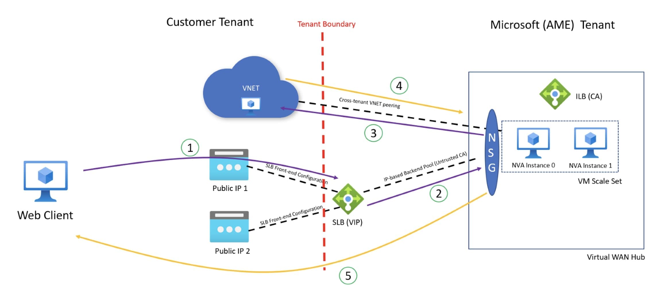
  • Leveraging Azure’s inbuilt capabilities of Internal Load Balancer (ILB).

  • Scaling of instances with predefined configuration during deployment.

Traffic Routing Through Threat Defense Virtual on Azure Virtual WAN

Routing Traffic Methods in Azure Virtual WAN

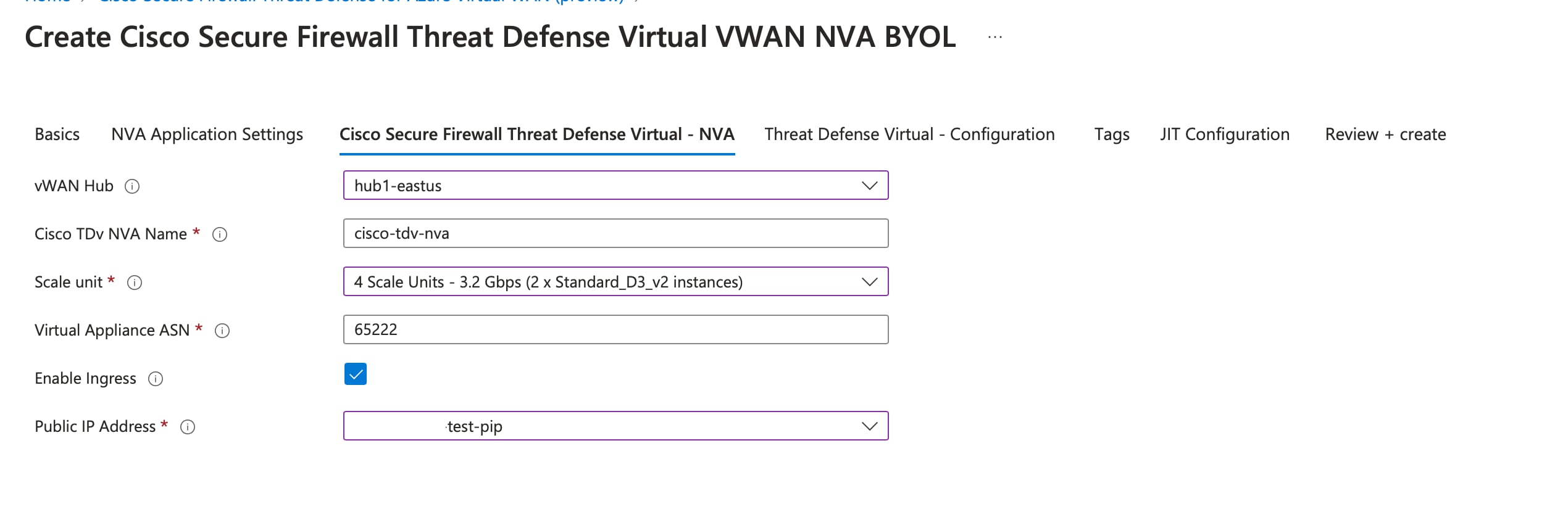
Azure Virtual WAN offers Border Gateway Protocol (BGP), a dynamic routing protocol that helps determine the best route to send traffic between different Azure networks while constantly updating and sharing the routing table. The virtual WAN hub provides a set of BGP endpoints (for High Availability) and Autonomous System Number (ASN), which you must configure as BGP neighbors for Threat Defense Virtual in the management center.

You can also use the static routing method to manually configure routes in the Threat Defense Virtual.

For more information on routing in Azure, see About BGP and VPN Gateway in the Azure documentation.

Routing Intent

Routing Intent is a routing ability in the Azure Virtual WAN hub that simplifies the process of forwarding Internet-bound and Private traffic to the Threat Defense Virtual firewall deployed in the hub for inspection.

For more information, see Routing Intent in the Azure documentation.

System Requirements

Scaling Units

The scaling required to achieve maximum throughput depends on the instance size and number of Firewall Threat Defense Virtual instances (NVA) you select or configure during deployment in the Azure Virtual WAN hub.

For example: If two Firewall Threat Defense Virtual instances with D3_V2 size can support 3.2 Gbps, then the NVA throughput is defined as Scale-Unit-4: 3.2 Gbps.

Table 1. Firewall Threat Defense Virtual Throughput Level Based on Instance Type

Scale Unit

Threat Defense Virtual instances

Instance Type

Throughput Support Level

4

2

Standard_D3_v2

3.2 Gbps

10

2

Standard_D4_v2

4.8 Gbps

20

2

Standard_D5_v2

12 Gbps

40

3

Standard_D5_v2

18 Gbps

60

4

Standard_D5_v2

24 Gbps

80

5

Standard_D5_v2

30 Gbps

Limitations

Interfaces

Firewall Threat Defense Virtual in an Azure Virtual WAN hub supports Three interfaces for deployment due to the restriction by Azure that an NVA can only support a maximum of three network interfaces.


Note


Firewall Threat Defense Virtual version 7.4.1 and later that supports the three interface models is compatible for deployment on Azure Virtual WAN.


Three subnets for the Firewall Threat Defense Virtual network interfaces are as follows:

  • Management interfaces – It is the first interface that connects the Firewall Threat Defense Virtual to the management center using a public IP address.

  • Outside interface (required) - It is the second interface that connects the Firewall Threat Defense Virtual to an untrusted public IP address.

  • Inside interface (required) - It is the third interface that connects the Firewall Threat Defense Virtual to the Virtual WAN hub and inside the host network on a trusted private IP address.

Firewall Threat Defense Virtual as Network Virtual Appliance (NVA)

The following are key features that are related to the network configuration of Firewall Threat Defense Virtual as NVA in Azure Virtual WAN.

  • Azure internally creates the VNet and subnets during the deployment of Firewall Threat Defense Virtual on Azure Virtual WAN. As a result, you cannot modify or create them after the deployment is complete. However, you can view all the IP addresses attached to the instance after the deployment.

  • You cannot choose the ports in network security groups for each interface, however, these ports are predefined during deployment. Only TCP ports 443, 8305, and 22 are allowed on the Management interface to connect to the internet.

  • The Inside interface only allows communication within the Azure Virtual WAN hub and internal networks that are connected to it.

Access Restriction to Firewall Threat Defense Virtual on the Azure Virtual WAN Hub

You require authorization to access the Firewall Threat Defense Virtual instances that are deployed on the hub as a managed application into a managed resource group. The administrator can grant limited or restricted access to this managed resource group.

Azure managed applications offers a just-in-time (JIT) access feature that allows you to define access to managed applications. For information on the JIT, see Azure Managed Applications overview and just-in-time in the Azure documentation.

IP Support

  • Only IPv4 is supported.

Unsupported Features

  • Bootstrapping via Day 0 / Custom data is not supported.

  • Firewall Threat Defense Virtual does not support streaming metrics to Azure.

  • Virtual Machine upgrade by replacing the operating system disk is not supported.

  • SSH key-based login to Firewall Threat Defense Virtual is not supported.

  • PAYG is not supported.

Licensing

BYOL using a Cisco Smart License Account.

Network Topology

Firewall Threat Defense Virtual, as an NVA in the Azure Virtual WAN hub, inspects network traffic routing through the hub from different on-premises networks (spoke) such as Internet, Branch (Sites), or as VNETs.

These traffic routes through which the network traffic is traversing is categorized into the following topologies:

  • East-West: Branch to Branch

  • East-West: VNet to VNet

  • North-South: Branch to Internet

  • North-South: VNet to Internet


Note


Traffic routing from Internet to VNet or Branch through Firewall Threat Defense Virtual is not supported.


Note


You can deploy multiple hubs across the Azure regions and connect to a Virtual WAN. Also, you can configure each hub to have its own Firewall Threat Defense Virtual for East-West and North-South traffic inspection.


North-South Traffic Inspection Topology by Firewall Threat Defense Virtual on a Single Virtual WAN Hub

This topology refers to Firewall Threat Defense Virtual inspecting the network traffic navigating between:

  • Branches and VNETs, and vice versa are connected to the Virtual WAN hub.

Figure 1. Firewall Threat Defense Virtual North-South Traffic Inspection Topology in Azure Virtual WAN Hub


The following steps explain the traffic flow process in the North-South traffic inspection.

  1. On-premises network sends traffic to Azure Gateway.

  2. Gateway forwards to ILB.

  3. ILB sends to Firewall Threat Defense Virtual (NVA)

  4. NVA SNATS to instances PIP and sends to the Internet.

  5. Web server replies to instance PIP Firewall Threat Defense Virtual (NVA) undoes SNAT and forwards to gateway.

  6. Gateway forwards to on-premises network.

East-West Traffic Inspection Topology by Firewall Threat Defense Virtual on a Single Virtual WAN Hub

This topology refers to Firewall Threat Defense Virtual inspecting the network traffic navigating between:

  • Branches and VNETs, and vice versa are connected to the Virtual WAN hub.

  • Internet to Branch or VNETs connected to the Virtual WAN hub.

Figure 2. Firewall Threat Defense Virtual East-West Traffic Inspection Topology in Azure Virtual WAN Hub
This topology refers to Firewall Threat Defense Virtual inspecting the network traffic navigating between Site-to-Site (Branch and Branch) and VNET-to-VNET that are connected to the Virtual WAN hub.

The following steps explains the traffic flow process in the East-West traffic inspection.

  1. VNet1 sends traffic to ILB.

  2. ILB chooses one of the active instances.

  3. Firewall Threat Defense Virtual (NVA) sends directly to the destination (VNet 2).

  4. VNet sends traffic to ILB.

  5. ILB forwards traffic to the appropriate Firewall Threat Defense Virtual (NVA) state fully.

  6. Firewall Threat Defense Virtual (NVA) sends traffic back to VNet 1.

Deploy Threat Defense Virtual on Azure Virtual WAN

You can use the Cisco Secure Firewall Threat Defense Virtual for Azure Virtual WAN offering that is available on Azure Marketplace to deploy Threat Defense Virtual on the Azure Virtual WAN hub.

Prerequisites

  • A Microsoft Azure account. You can create one at https://azure.microsoft.com/en-us/.

  • Create a hub on your Virtual WAN. For information on creating a virtual hub in Azure, see Create a hub in the Azure documentation.

  • Ensure that the Virtual WAN hub address space is less than or equal to /23.


    Note


    Microsoft Azure allows Virtual WAN hubs with /24 address spaces. However, Microsoft does not recommend the deployment of such hubs due to future enhancements. We do not support deploying Firewall Threat Defense Virtual in a Virtual WAN hub with a /24 address space.


  • A Cisco Smart Account. You can create one at Cisco Software Central.


Note


Post deployment of Threat Defense Virtual instances, you can view all the public and private IPs attached to the instance.


Communication Paths

  • Management interface—Used to connect the Threat Defense Virtual to the Management Center.

  • Inside interface (required)—Used to connect the Threat Defense Virtual to inside hosts.

  • Outside interface (required)—Used to connect the Threat Defense Virtual to the public network.

Deploy Threat Defense Virtual on Azure Virtual WAN Using Solution Template

The following instructions show how to deploy the Threat Defense Virtual on Azure Virtual WAN using the solution template that is available in the Azure Marketplace. This is a top-level list of steps to set up the Threat Defense Virtual in the Microsoft Azure Virtual WAN environment.

For more information about the Azure setup, see Getting Started with Azure.

Procedure


Step 1

Log in to the Azure Resource Manager (ARM) portal.

The Azure portal shows virtual elements that are associated with the current account and subscription regardless of data center location.

Step 2

Choose Azure Marketplace > Virtual Machines.

Step 3

Search the Marketplace for Cisco Secure Firewall Threat Defense Virtual for Azure VWAN, choose the offering, and click Create to display the Basics page.
Basics settings

Step 4

Configure the Basics settings.

  1. Choose your subscription.

  2. Select the geographical location or region of the Virtual WAN hub. Each deployment will have multiple resoorces such as virtual WAN hub, Threat Defense Virtual, Network, and storage accounts. Ensure that you select the same geographical location for all the resources.

Step 5

Configure Managed Application Details settings.

  1. Enter a name for managed application.

  2. Select the managed resource group where you deploy the Threat Defense Virtual instance.

Step 6

Click Next to display the Cisco Secure Firewall Threat Defense Virtual - NVA page.

Step 7

Configure the Virtual hub and the NVA details:

  1. Select the Virtual WAN hub from the vWAN Hub drop-down list to deploy a Threat Defense Virtual instance.

  2. Enter an appropriate name for the Threat Defense Virtual instance you are deploying.

  3. Select the scale units that define the number of Threat Defense Virtual instances you want to deploy.

    You can select the required scale unit to achieve the needed NVA throughput level. For example, selecting 4 Scale Units – 3.2 Gbps (2 x Standard_D3_v2_instances) implies “Number scale unitThroughput level (2 Threat Defense Virtual with instance type).

    Note


    Scale unit defines the number of Threat Defense Virtual instances and its associated instance type that you are deploying in the hub.

  4. Enter the Virtual Appliance ASN.

    Note


    The ASN value that you enter must be within the range 64512 – 65534.

Step 8

Click Next to display the Threat Defense Virtual - Configuration page.
Threat Defense Virtual - Configuration

Step 9

Select the appropriate NVA Software version compatible version from the drop-down list.

Note


This field provides a list of NVA software versions compatible with the corresponding Threat Defense Virtual version you are deploying. Ensure to select the appropriate version from the list.

Step 10

Create and confirm the admin password that is required to access the managed resource group containing Threat Defense Virtual instances. This is the password that is used for accessing Threat Defense Virtual instances.

Step 11

Click Yes to enter the FMC registration information.

  1. Enter the FMC IP address.

  2. Enter the FMC Registration Key for registering the Threat Defense Virtual instances.

    Note

     
    • The FMC Registration key must be an alphanumeric string of 1 – 37 characters in length. You will enter this key on the Management Center when adding Threat Defense Virtual.

  3. [Optional] Enter the management center NAT ID that is used during instance registration.

    Note

     
    • The NAT ID must be an alphanumeric string between 1 – 37 characters in length and is used only during the registration process between the Management Center and the device when one side does not specify an IP address. The NAT ID is essentially a one-time password, so it must be unique and not used by any other devices awaiting registration. To ensure successful registration, be sure to specify the same NAT ID on the FMC when adding the Threat Defense Virtual.

Step 12

Click Next to configure the Tags.
Tags configuration

Step 13

Click Next to display the JIT configuration page.
JIT Configuration

By default, the Enable JIT access option is set to Yes, which enables JIT for provisioning access to manage and troubleshoot the Threat Defense Virtual instances.

Step 14

Click Next to display the Review+Create page.
Review and Create page

Step 15

Before deploying, you must review the subscription, NVA, Threat Defense Virtual and JIT configuration details, accept the Terms and conditions and then click Create to deploy the Threat Defense Virtual (NVA) on the Virtual WAN hub.

Step 16

Go to Home > Security > Third-party providers, and click Network Virtual Appliance to view the NVA created on the hub.
Network Virtual Appliance

Step 17

Click the NVA to view all the Threat Defense Virtual instances deployed.

You can access the Threat Defense Virtual using the management public IP address of the instance and login using the SSH.

Note


The public IP addresses of each Threat Defense Virtual instance that you deploy on the hub is used for registering the instances in the management center.


What to do next

Register and configure the Threat Defense Virtual instances that you deployed on the hub in the management center.

Configure Threat Defense Virtual in Management Center

You configure each Threat Defense Virtual instance deployed on the hub through the management center.

Create all the objects needed for the Threat Defense Virtual configuration and management, including a device group, so you can easily deploy policies and install updates on multiple devices. All the configurations applied on the device group will be pushed to the Threat Defense Virtual instances.

This section provides a brief overview of the basic steps to configure the Threat Defense Virtual instances in the management center.

For more information, see Cisco Secure Firewall Management Center Device Configuration Guide.

Register Threat Defense Virtual Instances in the Management Center

You must register all the Threat Defense Virtual instances that are deployed in the virtual WAN hub under a common Device group in the management center. It helps you to quickly deploy policies and configurations to those instances.

Before you begin

  • Require the management public IP address of each Threat Defense Virtual instance deployed in the Azure Virtual WAN hub. It is used to set up and register instances in the management center.

  • Create a Device Group in the management center. See Add a Device Group.

  • Create an Access Control Policy. See Creating a Basic Access Control Policy.

  • FMC Registration Key created during Threat Defense Virtual deployment in the hub.

Procedure


Step 1

Log in to the Management Center.

Step 2

Choose Devices > Device Management.

Step 3

Click Add > Device

Step 4

Enter the public IP address of the Threat Defense Virtual instance deployed in the hub.

Step 5

Provide the display name for the Threat Defense Virtual instance.

Step 6

Enter the Registration Key of the management center that you have created during the Threat Defense Virtual deployment in the hub.

Step 7

From the Group drop-down list, choose the device group to which you want to add the Threat Defense Virtual instance.

Step 8

From the Access Control Policy drop-down list, select the policy that you want to apply to the Threat Defense Virtual instance.

Step 9

Enter other details as required.

Step 10

Click Register.

Step 11

Repeat Step 1 through Step 10 to register other Threat Defense Virtual instances.


What to do next

Configure interfaces of Threat Defense Virtual instances.

Configure Interfaces

After registering the Threat Defense Virtual instance, you must configure its interfaces in the management center.

The Azure Virtual WAN supports only three interfaces, which is configured as follows:

  • Management interface with the public IP as the first interface.

  • Outside interface with the public IP as the second interface.

  • Inside interface with the private IP as the third interface (which has only private IP).

Procedure


Step 1

Log in to the Management Center.

Step 2

Go to the Devices page.

Step 3

Click the Edit icon corresponding to the Threat Defense Virtual you have registered.

Step 4

Click the Edit icon corresponding to an interface. For example, GigbitEthernet0/0.

Step 5

Enter the name of the first interface as outside.

Step 6

Check the Enabled check box to enable the interface.

Step 7

From the Security Zone drop-down list, select outside.

Step 8

Click the IPv4 menu to assign the type of IP to the interface.

Step 9

From the IP Type drop-down list, select Use DHCP to configure your interface to obtain an IP address from DHCP.

Step 10

Check the Obtain default route using DHCP check box.

Step 11

Enter the Default route metric as 1.

Step 12

Click OK to save the configuration.

Step 13

Repeat Step 1 through Step 10 to configure the Inside interface.


What to do next

Configure routes for interfaces.

Configure Route for Interfaces

Configure the static routes for Outside and Inside interfaces by creating network objects and assigning the gateway IP address.

  • The Outside interface route configuration uses the gateway IP address as the default route for all the packets.

  • The Inside interface route configuration uses the gateway IP address as the default route for the health probe packets and the packets that are destined for the hub network range.

The gateway IP address is computed using each interface's IP address and subnet mask address.

Compute Gateway IP Address for Outside and Inside Interface

This section explains the process of computing the gateway IP address for the Outside and Inside interfaces with an example.

Procedure


Step 1

Log in to the Management Center.

Step 2

Go to the Devices > Device Management.

Step 3

Access the Firewall Threat Defense Virtual instance you have deployed on the hub.

Step 4

In the >_Command field, enter show interface GigbitEthernet 0/0 to get the Outside interface configuration or show interface GigbitEthernet 0/1 to get the Inside interface configuration details.

Step 5

Repeat Step 1 through Step 4 to get the IP address and subnet mask addresses for the Inside interface or Outside interface.

Step 6

Note the IP address and subnet mask addresses from the command result.

Step 7

Compute the gateway IP addresses for Inside and Outside by following the example:

  • To compute gateway IP address for Outside interface:

    For Example: For GigabitEthernet0/0 (Outside interface)

    IP address - 15.0.112.136

    Subnet mask - 255.255.255.128

    Hence, compute the gateway IP address as (that is the first IP address in this subnet) 15.0.112.129.

  • To compute gateway IP address for Inside interface:

    For Example: For GigabitEthernet0/1 (Inside interface)

    IP address - 15.0.112.10

    Subnet mask - 255.255.255.128

    Hence, compute the gateway IP as (that is the first IP address in this subnet) 15.0.112.1.


What to do next

Configure default route for Inside and Outside interfaces.

Configure Default Route for Outside Interface

Procedure


Step 1

Log in to the Management Center.

Step 2

Go to the Devices > Device Management.

Step 3

Click the Firewall Threat Defense Virtual instance.

Step 4

Click Routing > Static Route.

Step 5

Click Add Route.

Step 6

From the Interface drop-down list, select Outside.

Step 7

Select any-ipv4 for the Outside interface under Available Network and click Add.

Step 8

Enter the gateway IP address:

  1. Click the + icon to add a network object.

  2. Enter the name and description of the network object.

  3. Click the Host network.

  4. Enter the gateway IP address of the Outside interface that you have computed.

  5. Click Save.


Configure Default Route for Inside Interface

Before you begin

You must have the CIDR IP address of the Firewall Threat Defense Virtual deployed on the hub. You require this to configure the Inside interface.

Procedure


Step 1

Log in to the Management Center.

Step 2

Go to the Devices > Device Management.

Step 3

Click the Firewall Threat Defense Virtual instance.

Step 4

Click Routing > Static Route.

Step 5

Click Add Route.

Step 6

From the Interface drop-down list, select Inside.

Step 7

Add the network object to configure the Inside interface with the CIDR IP address of the hub.

  1. Click the + icon to add a network object.

  2. Enter the name and description of the network object.

  3. Click the Host network.

  4. Enter the CIDR IP address (Private address space) of the hub.

  5. Click Save.

Step 8

Add the network object to configure the Inside interface with the load balancer health probe IP address.

  1. Click the + icon to add a network object.

  2. Enter the name and description of the network object.

  3. Click the Host network.

  4. Enter the IP address of the load balancer health probe. For example:168.63.129.16.

    This IP address is a standard or fixed address.

Step 9

Enter the gateway IP address:

  1. Click the + icon to add a network object.

  2. Enter the name and description of the object.

  3. Click the Host network.

  4. Enter the gateway IP address of the Inside interface that you have computed.

  5. Click Save.


Configure Traffic Routing

Note that you can configure either static routing or Border Gateway Protocol (BGP) for data exchange between the Threat Defense Virtual instances and the hub. These are two different routing methods that you can configure for network traffic in a Virtual WAN hub.

BGP is a dynamic routing protocol that factors the route based on the real-time traffic exchange between the hub and your threat defense virtual appliance. Whereas the static routing uses a preconfigured routing protocol to exchange traffic.

For more information about Azure Virtual WAN, refer to the Microsoft Azure Virtual WAN documentation.

Configure Static Routing

Procedure


Step 1

Log in to the Management Center.

Step 2

Go to the Devices > Device Management.

Step 3

Click the Threat Defense Virtual instance.

Step 4

Click Routing > Static Route.

Step 5

Click Add Route.

Step 6

From the Interface drop-down list, select Outside.

If you are configuring the Inside interface, select Inside.

Step 7

Add the network object IP address:

  1. Click the + icon to add a network object.

  2. Enter the name and description of the object.

  3. Click the Host network.

  4. Enter the IP address.

  5. Click Save.


Enable BGP Routing

Procedure


Step 1

Log in to the Management Center.

Step 2

Choose Devices > Device Management.

Step 3

Click the Threat Defense Virtual instance.

Step 4

Click the Routing menu.

Step 5

Click BGP under General Settings.

Step 6

Check the Enable BGP check box.

Step 7

Enter the AS number of your virtual hub.

Step 8

Click Save.


What to do next

Configure BGP neighbors.

Configure BGP Neighbors

Procedure


Step 1

Log in to the Management Center.

Step 2

Choose BGP > IPv4 > Neighbor.

Step 3

Check the Enable IPv4 check box.

Step 4

Enter the Autonomous System (AS) number of your virtual hub.

Step 5

Click Add in the Neighbor.

Step 6

Enter the first IP address of the BGP endpoint that you have noted.

Step 7

Check the Enabled address check box.

Step 8

Enter the AS number in the Remote AS field.

Step 9

Check the Disable Connection Verification check box on the Advanced menu.

Step 10

Click Save.

Step 11

Repeat Step 1 through Step 8 to add the second IP address of the BGP endpoint.


What to do next

Verify BGP route configuration.

Verify BGP Route Configuration

Before you begin

After configuring the BGP endpoints, you must verify whether a connection through the BGP endpoints is established between Threat Defense Virtual and the virtual WAN hub.

Procedure


Step 1

Log in to the Management Center.

Step 2

Choose Devices > Device Management.

Step 3

Click the Threat Defense Virtual instance.

Step 4

Click CLI in the Device > General widget.

Step 5

In the >_Command field, enter show route to view and verify the connection status.

Note


Code B indicates the BGP endpoint connection status with the Threat Defense Virtual.


Configure Health Probe

To ensure the Threat Defense Virtual status is stable, you must configure the Inside interface (Trusted) that connects to the Internal Load Balancer (ILB). The ILB performs periodic health check probes through the TCP port 443 to verify the response from Threat Defense Virtual.

Procedure


Step 1

Log in to the Management Center.

Step 2

Choose Devices > Platform Settings > New Policy > Threat Defense Settings.

Step 3

Add a New policy for the Threat Defense Virtual to connect to the load balancer.

Step 4

Edit the new policy that you have added.

Step 5

Check the Enable HTTP Server check box, and enter 443 in the Port field.

Step 6

Click + Add to configure the HTTP address.

Step 7

Select the health probe IP address name.

Step 8

Select the required IP address from the Available Zone/Interface and click Add to add it to Selected Zones/Interfaces.

Step 9

Click OK.

Step 10

Choose Devices > Device Management.

Step 11

Click the edit icon in the Applied Policies widget.

Step 12

Select this policy from the Platform Settings drop-down list.

Step 13

Update and apply the security policies as required.

For more information about configuring HTTP Access, see Configuring HTTP.


Troubleshooting

The following are common error scenarios and debugging tips for the Threat Defense Virtual in Virtual WAN:

  • Traffic is not routed to Threat Defense Virtual.

    • Verify the Threat Defense Virtual response to health probe checks in the management center.

    • Verify whether the derived gateway IP addresses of the Inside and Outside interfaces are correct.

    • Check the static route.

  • Non-RFC RFC 1918 not reaching Threat Defense Virtual: Ensure Non-RFC 1918 ranges that are explicitly specified as Private addresses in the Routing Intent.

  • Threat Defense deployment error: If you encounter the Error: Hub Prefix Length should be less or equal to 23 during Threat Defense Virtual deployment, then ensure that the CIDR of the HUB address space is less than or equal to /23.