- Cisco x90 Series Content Security Appliances Installation and Maintenance Guide
- Table of Contents
- About this Book
- Install Cisco x90 Series Content Security Appliances
- Cisco C190 Email Security Appliance
- Cisco C390 Email Security Appliance
- Cisco C690 Email Security Appliance
- Cisco M190 Content Security Management Appliance
- Cisco M390 Content Security Management Appliance
- Cisco M690 Content Security Management Appliance
- Cisco S190 Web Security Appliance
- Cisco S390 Web Security Appliance
- Cisco S690 Web Security Appliance
- Maintain Cisco Content Security Appliances
- Appliance Specifications
- Power Cord Specifications
Maintain Cisco Content Security Appliances
Monitor System Health
Information about using SNMP to monitor system health is available in the user documentation for your AsyncOS release at the following URLs:
- http://www.cisco.com/c/en/us/support/security/email-security-appliance/products-user-guide-list.html
- http://www.cisco.com/c/en/us/support/security/content-security-management-appliance/products-user-guide-list.html
- http://www.cisco.com/c/en/us/support/security/web-security-appliance/products-user-guide-list.html
Prepare for Cisco Content Security Appliance Component Replacement
- Required Equipment
- Shut Down and Power Off the Appliance
- Serial Number Location
- Hot-Swap Replacement
Required Equipment
The following equipment is used to perform the procedures in this chapter:
Shut Down and Power Off the Appliance
The appliance can run in two power modes:
- Main power mode—Power is supplied to all appliance components and the operating system.
- Standby power mode—Power is supplied only to the service processor and the cooling fans and it is safe to power off the appliance from this mode.
You can gracefully shut down the appliance by using the shutdown command or the Power button on the appliance front panel, as described in the following steps:
Step 1![]() Check the color of the Power Status LED.
Check the color of the Power Status LED.
- Green—The appliance is in main power mode and must be shut down before it can be safely powered off. Go to Step 2.
- Amber—The appliance is already in standby mode and can be safely powered off. Go to Step 3.
Step 2![]() Use one the following methods to shut down the appliance. If possible, invoke a graceful shutdown. Otherwise invoke a hard shutdown:
Use one the following methods to shut down the appliance. If possible, invoke a graceful shutdown. Otherwise invoke a hard shutdown:

- Graceful shutdown using the CLI—Enter the shutdown command. The operating system performs a graceful shutdown and the appliance goes to standby mode, which is indicated by an amber Power Status LED.
- Graceful shutdown using the front panel—Press and release the Power button. The operating system performs a graceful shutdown and the appliance goes to standby mode, which is indicated by an amber Power Status LED.
- Emergency shutdown—Press and hold the Power button for 4 seconds to force the main power off and immediately enter standby mode.
Step 3![]() Disconnect the power cords from the power supplies in your appliance to completely power off the appliance.
Disconnect the power cords from the power supplies in your appliance to completely power off the appliance.
Serial Number Location
The serial number (SN) for the appliance is printed on a label on the top of the appliance, near the front.
Hot-Swap Replacement
Some components can be removed and replaced without powering off and removing AC power from the appliance.
Replace Cisco Content Security Appliance Components

Warning![]() Blank faceplates and cover panels serve three important functions: they prevent exposure to hazardous voltages and currents inside the chassis; they contain electromagnetic interference (EMI) that might disrupt other equipment; and they direct the flow of cooling air through the chassis. Do not operate the system unless all cards, faceplates, front covers, and rear covers are in place.
Blank faceplates and cover panels serve three important functions: they prevent exposure to hazardous voltages and currents inside the chassis; they contain electromagnetic interference (EMI) that might disrupt other equipment; and they direct the flow of cooling air through the chassis. Do not operate the system unless all cards, faceplates, front covers, and rear covers are in place.
Statement 1029

Tip![]() You can press the Unit Identification button on the front panel or rear panel to turn on a flashing Unit Identification LED on the front and rear panels of the appliance. This button allows you to locate the specific appliance that you are servicing when you go to the opposite side of the rack. See the “Prepare for Cisco Content Security Appliance Component Replacement” section for locations of these LEDs.
You can press the Unit Identification button on the front panel or rear panel to turn on a flashing Unit Identification LED on the front and rear panels of the appliance. This button allows you to locate the specific appliance that you are servicing when you go to the opposite side of the rack. See the “Prepare for Cisco Content Security Appliance Component Replacement” section for locations of these LEDs.
This section describes how to replace appliance components, and it includes the following topics:
Replace Hard Drives or Solid State Drives
Drive Population Guidelines
The 90-Series Cisco Content Security Appliances are available in the following models:
- Cisco C190, M190, S190, and C390 —Two small form-factor (SFF) drives
- Cisco S390 and C690 —Four SFF drives
- Cisco M390 —Six SFF drives
- Cisco M390X, C690X, C690-1G, and C690-10G —Eight SFF drives
- Cisco M690 —Ten SFF drives
- Cisco M690X, M690-1G, M690-10G, S690X, S690-1G, and S690-10G—Sixteen SFF drives

Note![]() You cannot change the backplane type after-factory. To change a front panel/backplane configuration, a chassis replacement is required.
You cannot change the backplane type after-factory. To change a front panel/backplane configuration, a chassis replacement is required.
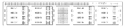
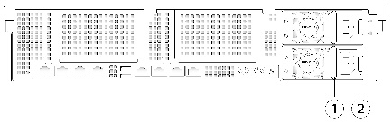
The drive-bay numbering for all versions is shown in Figure 11-1 and Figure 11-2.
Figure 11-1 Drive Numbering for 1RU Appliances
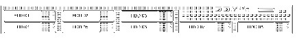
Figure 11-2 Drive Numbering for 2RU Appliances
Observe these drive population guidelines for optimal performance:
Drive Replacement Procedure
Tip![]() You do not have to shut down or power off the appliance to replace SAS hard drives because they are hot-swappable.
You do not have to shut down or power off the appliance to replace SAS hard drives because they are hot-swappable.
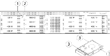
Step 1![]() Remove the drive that you are replacing or remove a blank drive tray from an empty bay:
Remove the drive that you are replacing or remove a blank drive tray from an empty bay:
a.![]() Press the release button on the face of the drive tray. See Figure 11-3.
Press the release button on the face of the drive tray. See Figure 11-3.
b.![]() Grasp and open the ejector lever and then pull the drive tray out of the slot.
Grasp and open the ejector lever and then pull the drive tray out of the slot.
c.![]() If you are replacing an existing drive, remove the four drive-tray screws that secure the drive to the tray and then lift the drive out of the tray.
If you are replacing an existing drive, remove the four drive-tray screws that secure the drive to the tray and then lift the drive out of the tray.
a.![]() Place a new drive in the empty drive tray and replace the four drive-tray screws.
Place a new drive in the empty drive tray and replace the four drive-tray screws.
b.![]() With the ejector lever on the drive tray open, insert the drive tray into the empty drive bay.
With the ejector lever on the drive tray open, insert the drive tray into the empty drive bay.
c.![]() Push the tray into the slot until it touches the backplane, and then close the ejector lever to lock the drive in place.
Push the tray into the slot until it touches the backplane, and then close the ejector lever to lock the drive in place.
Figure 11-3 Replace Drives on 1RU Appliances
|
|
|
||
|
|
|
Replace Power Supplies
The appliance can have one or two power supplies. When two power supplies are installed, they are redundant and hot-swappable, with one active power supply and one standby (1+1).
This appliance also supports cold redundancy. Depending on the power being drawn by the appliance, one power supply might actively provide all power to the system while the remaining power supply is put into a standby state. For example, if you have two supplies connected to AC power, but the power consumption can be satisfied by power supply 1, then power supply 2 is put into a standby state.
- See Environmental Specifications for more information about the supported power supplies.
- See Install a DC Power Supply for information about wiring a DC power supply.
Note![]() If you have ordered an appliance with power supply redundancy (two power supplies), you do not have to power off the appliance to replace power supplies because they are redundant as 1+1 and hot-swappable.
If you have ordered an appliance with power supply redundancy (two power supplies), you do not have to power off the appliance to replace power supplies because they are redundant as 1+1 and hot-swappable.
Note![]() Do not mix power supply types in the appliance. Both power supplies must be the same wattage and Cisco product ID (PID).
Do not mix power supply types in the appliance. Both power supplies must be the same wattage and Cisco product ID (PID).
Step 1![]() Remove the power supply that you are replacing or a blank panel from an empty bay:
Remove the power supply that you are replacing or a blank panel from an empty bay:
a.![]() Perform one of the following actions:
Perform one of the following actions:
–![]() If your appliance has only one power supply, shut down and power off the appliance as described in Shut Down and Power Off the Appliance.
If your appliance has only one power supply, shut down and power off the appliance as described in Shut Down and Power Off the Appliance.
–![]() If your appliance has two power supplies, you do not have to shut down the appliance.
If your appliance has two power supplies, you do not have to shut down the appliance.
b.![]() Remove the power cord from the power supply that you are replacing.
Remove the power cord from the power supply that you are replacing.
For a DC power supply, release the electrical connector block from the power supply by pushing the orange plastic button on the top of the connector inward toward the power supply (see Figure 11-4). Pull the connector block from the power supply.
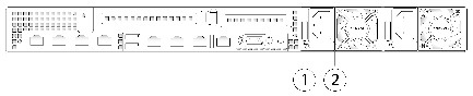
c.![]() Grasp the power supply handle while pinching the green release lever towards the handle (see Figure 11-5).
Grasp the power supply handle while pinching the green release lever towards the handle (see Figure 11-5).
d.![]() Pull the power supply out of the bay.
Pull the power supply out of the bay.
Step 2![]() Install a new power supply:
Install a new power supply:
a.![]() Grasp the power supply handle and insert the new power supply into the empty bay.
Grasp the power supply handle and insert the new power supply into the empty bay.
b.![]() Push the power supply into the bay until the release lever locks.
Push the power supply into the bay until the release lever locks.
c.![]() Connect the power cord to the new power supply.
Connect the power cord to the new power supply.
For a DC power supply, push the electrical connector block into the power supply.
d.![]() If you shut down the appliance, press the Power button to return the appliance to main power mode.
If you shut down the appliance, press the Power button to return the appliance to main power mode.
Figure 11-4 Replace Power Supplies on 1RU Appliances
|
|
|
Figure 11-5 Replace Power Supplies on 2RU Appliances
|
|
|
Install a DC Power Supply
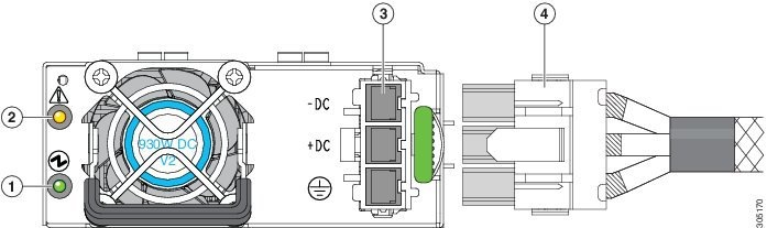
The x690 models of Cisco Content Security Appliances are available with optional 930W DC power supplies. The part number for the Version 2 930W DC power supply is CCS-PWR-DCV2-930W.
Warning![]() A readily accessible two-poled disconnect device must be incorporated in the fixed wiring. Statement 1022
A readily accessible two-poled disconnect device must be incorporated in the fixed wiring. Statement 1022
Warning![]() This product requires short-circuit (overcurrent) protection, to be provided as part of the building installation. Install only in accordance with national and local wiring regulations. Statement 1045
This product requires short-circuit (overcurrent) protection, to be provided as part of the building installation. Install only in accordance with national and local wiring regulations. Statement 1045
Warning![]() When installing or replacing the unit, the ground connection must always be made first and disconnected last. Statement 1046
When installing or replacing the unit, the ground connection must always be made first and disconnected last. Statement 1046
Warning![]() Installation of the equipment must comply with local and national electrical codes. Statement 1074
Installation of the equipment must comply with local and national electrical codes. Statement 1074
Warning![]() Hazardous voltage or energy may be present on DC power terminals. Always replace cover when terminals are not in service. Be sure uninsulated conductors are not accessible when cover is in place. Statement 1075
Hazardous voltage or energy may be present on DC power terminals. Always replace cover when terminals are not in service. Be sure uninsulated conductors are not accessible when cover is in place. Statement 1075
If you are using the Version 2 930W DC power supply, you connect power using a supplied 3-wire cable with a keyed connector that plugs into a fixed power input socket on the power supply.
Warning![]() Before beginning this wiring procedure, turn off the DC power source from your facility’s circuit breaker to avoid electric shock hazard.
Before beginning this wiring procedure, turn off the DC power source from your facility’s circuit breaker to avoid electric shock hazard.
Step 1![]() Turn off the DC power source from your facility’s circuit breaker to avoid electric shock hazard.
Turn off the DC power source from your facility’s circuit breaker to avoid electric shock hazard.
Step 2![]() Wire the supplied 3-wire connector cable to your facility’s DC power source. Attach the red wire to the negative lead of your facility’s DC power source.
Wire the supplied 3-wire connector cable to your facility’s DC power source. Attach the red wire to the negative lead of your facility’s DC power source.
Note![]() The supplied connector cable contains 8 AWG gauge wires. The recommended facility wire gauge is 8 AWG. The minimum facility wire gauge is 10 AWG.
The supplied connector cable contains 8 AWG gauge wires. The recommended facility wire gauge is 8 AWG. The minimum facility wire gauge is 10 AWG.
Step 3![]() Plug the supplied connector cable into the power input socket on the power supply. Figure 11-6 shows that the connector is keyed to the socket so that the polarity is aligned correctly.
Plug the supplied connector cable into the power input socket on the power supply. Figure 11-6 shows that the connector is keyed to the socket so that the polarity is aligned correctly.
Figure 11-6 Version 2 930 W, –48 VDC Power Supply Connector Block
|
|
|
||
|
|
|
Step 4![]() Return power from your facility’s DC power source at the circuit breaker.
Return power from your facility’s DC power source at the circuit breaker.
Step 5![]() Verify that power supply status LED is green.
Verify that power supply status LED is green.
Enable Remote Power Cycling
If you want to be able to remotely reset appliance power, you must enable and configure this functionality in advance, using the procedure described in this section.
Note![]() The RPC port speed is configured statically to 100 mbps and full-duplex mode without autonegotiation. Without autonegotiation, the RPC port fails to connect properly and cannot be used.
The RPC port speed is configured statically to 100 mbps and full-duplex mode without autonegotiation. Without autonegotiation, the RPC port fails to connect properly and cannot be used.
- Cable the dedicated RPC port directly to a secure network.
- Ensure that the appliance is accessible remotely; for example, open any necessary ports through the firewall.
- This feature requires a unique IPv4 address for the dedicated RPC interface. This interface is configurable only via the procedure described in this section; it cannot be configured using the ipconfig command.
- To cycle appliance power, you will need a third-party tool that can manage devices that support the Intelligent Platform Management Interface (IPMI) version 2.0. Ensure that you are prepared to use such a tool.
- For more information about accessing the CLI, see the CLI reference guide.
Step 1![]() Use SSH or the serial console port to access the command-line interface.
Use SSH or the serial console port to access the command-line interface.
Step 2![]() Sign in using an account with Administrator access.
Sign in using an account with Administrator access.
Step 3![]() Enter the following commands:
Enter the following commands:
Step 4![]() Follow the prompts to specify the following:
Follow the prompts to specify the following:
These credentials are independent of other credentials used to access your appliance.
Step 5![]() Enter
Enter commit to save your changes.
Step 6![]() Test your configuration to be sure that you can remotely manage appliance power.
Test your configuration to be sure that you can remotely manage appliance power.
Step 7![]() Ensure that the credentials that you entered will be available to you in the indefinite future. For example, store this information in a safe place and ensure that administrators who may need to perform this task have access to the required credentials.
Ensure that the credentials that you entered will be available to you in the indefinite future. For example, store this information in a safe place and ensure that administrators who may need to perform this task have access to the required credentials.
Remotely Reset Appliance Power
If the appliance requires a hard reset, you can reboot the appliance chassis remotely using a third-party Intelligent Platform Management Interface (IPMI) tool.
For details, see Enable Remote Power Cycling.
status, on, off, cycle, reset, diag, soft
Issuing unsupported commands will produce an “insufficient privileges” error.
- Obtain and set up a utility that can manage devices using IPMI version 2.0.
- Understand how to use the supported IPMI commands. See the documentation for your IPMI tool.
Step 1![]() Use IPMI to issue a supported power-cycling command to the IP address assigned to the Remote Power Cycle port, which you configured earlier, along with the required credentials.
Use IPMI to issue a supported power-cycling command to the IP address assigned to the Remote Power Cycle port, which you configured earlier, along with the required credentials.
For example, from a UNIX-type machine with IPMI support, you might issue the command:
ipmitool -I lan -H 192.0.2.1 -U remoteresetuser -P password chassis power reset
where 192.0.2.1 is the IP address assigned to the Remote Power Cycle port and remoteresetuser and password are the credentials that you entered while enabling this feature.
Step 2![]() Wait at least eleven minutes for the appliance to reboot.
Wait at least eleven minutes for the appliance to reboot.
 フィードバック