Cisco M690 Content Security Management Appliance
Available Models
The Cisco M690 Content Security Management Appliance is available in the following models:
- M690—Ethernet data ports and ten small form-factor (SFF) drives, with a ten-drive backplane
- M690X—Ethernet data ports and sixteen SFF drives, with a sixteen-drive direct-connect backplane
- M690-1G—Two 1-Gigabit Fiber Optic ports and sixteen SFF drives
- M690-10G—Two 10-Gigabit Fiber Optic ports and sixteen SFF drives
Note You cannot change the panel/backplane type after-factory. If you want a different front panel/backplane configuration, you must order a another model.
Rear Panel Ports
The Cisco M690 Content Security Management Appliance is available with either Ethernet ports or Fiber Optic ports. The description of these ports are described in separate sections below.
Models with Ethernet Ports
The M690 and M690X models of the Cisco Content Security Management Appliance have Ethernet ports.
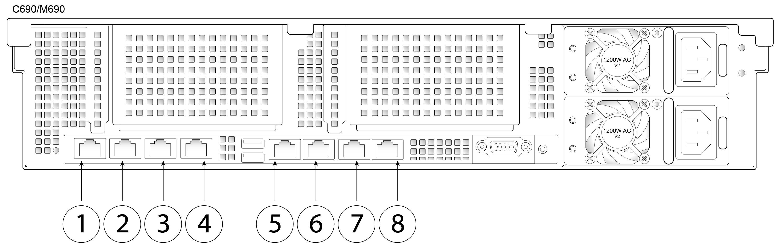
Figure 7-1 shows the rear panel ports of the Cisco M690 Content Security Management Appliance with Ethernet ports.
For information about rear panel LEDs, see Rear Panel LEDs and Buttons.
Figure 7-1 Rear Panel Ports of the M690 and M690X Content Security Management Appliances
|
|
Data 1 1-Gigabit Ethernet customer data interface |
|
Data 2 1-Gigabit Ethernet customer data interface |
|
|
Data 3 1-Gigabit Ethernet customer data interface |
|
Data 4 1-Gigabit Ethernet customer data interface |
|
|
RPC port The RPC port speed is configured statically to 100 mbps and full-duplex mode without autonegotiation. Without autonegotiation, the RPC port fails to connect properly and cannot be used. |
|
Console Directly connects a computer to the appliance |
|
|
Data 5 1-Gigabit Ethernet customer data interface |
|
Management interface 1-Gigabit Ethernet interface; management use only |
Models with Fiber Optic Ports
The M690-1G and M690-10G models of the Cisco Content Security Management Appliance have Fiber Optic ports.
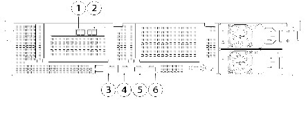
Figure 7-2 shows the rear panel ports of Cisco Content Security Management Appliances with Fiber Optic ports.
For information about rear panel LEDs, see Rear Panel LEDs and Buttons.
Figure 7-2 Rear Panel Ports of the M690-1G and M690-10G Models of Cisco 90-Series Content Security Management Appliances
|
|
Data 2 1-Gigabit or 10-Gigabit fiber optic customer data interface |
|
Data 3 -Gigabit or 10-Gigabit fiber optic customer data interface |
|
|
RPC port The RPC port speed is configured statically to 100 mbps and full-duplex mode without autonegotiation. Without autonegotiation, the RPC port fails to connect properly and cannot be used. |
|
Console Directly connects a computer to the appliance |
|
|
Data 1 -Gigabit or 10-Gigabit fiber optic customer data interface |
|
Management 1-Gigabit Ethernet interface; management use only |
Using Status LEDs and Buttons for Maintenance
Front Panel LEDs
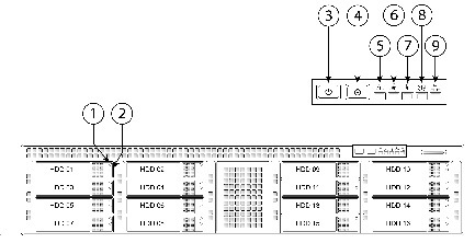
Figure 7-3 shows the front panel LEDs. Table 7-1 defines the LED states.
Figure 7-3 Cisco M690 Content Security Management Appliance Front Panel LEDs
|
|
Hard drive fault LED |
|
Fan status LED |
|
|
Hard drive activity LED |
|
Temperature status LED |
|
|
Power button/power status LED |
|
Power supply status LED |
|
|
Identification button/LED |
|
Network link activity LED |
|
|
System status LED |
|
|
Table 7-1 Front Panel LEDs, Definitions of States
| |
|
|
1 |
Hard drive fault |
- Off—The hard drive is operating properly.
- Amber—Drive fault detected.
- Amber, flashing—The device is rebuilding.
- Amber, flashing with one-second interval—Drive locate function activated.
|
2 |
Hard drive activity |
- Off—There is no hard drive in the hard drive tray (no access, no fault).
- Green—The hard drive is ready.
- Green, flashing—The hard drive is reading or writing data.
|
3 |
Power button/LED |
- Off—There is no AC power to the appliance.
- Amber—The appliance is in standby power mode. Power is supplied only to the Baseboard Management Controller (BMC) and some motherboard functions which enable you to use remote power commands.
- Green—The appliance is in main power mode. Power is supplied to all appliance components.
|
4 |
Unit Identification |
- Off—The unit identification function is not in use.
- Blue—The unit identification function is activated.
|
5 |
System status |
- Green—The appliance is running in a normal operating condition.
- Green, flashing—The appliance is performing system initialization and memory check.
- Amber—The appliance is in a degraded operational state. For example:
– Power supply redundancy is lost. – CPUs are mismatched. – At least one CPU is faulty. – At least one DIMM is faulty. – At least one drive in a RAID configuration failed.
- Amber, flashing—The appliance is in a critical fault state. For example:
– Boot failed. – Fatal CPU and/or bus error is detected. – The appliance is in an over-temperature condition. |
6 |
Fan status |
- Green—All fan modules are operating properly.
- Amber—One or more fan modules breached the critical threshold.
- Amber, flashing—One or more fan modules breached the non-recoverable threshold.
|
7 |
Temperature status |
- Green—The appliance is operating at normal temperature.
- Amber—One or more temperature sensors breached the critical threshold.
- Amber, flashing—One or more temperature sensors breached the unrecoverable threshold.
|
8 |
Power supply status |
- Green—All power supplies are operating normally.
- Amber—One or more power supplies are in a degraded operational state.
- Amber, flashing—One or more power supplies are in a critical fault state.
|
9 |
Network link activity |
- Off—The Ethernet link is idle.
- Green—One or more Ethernet LOM ports are link-active, but there is no activity.
- Green, flashing—One or more Ethernet LOM ports are link-active, with activity.
|
Rear Panel LEDs and Buttons
The rear panel has the following LEDs and buttons that can be used to maintain the appliance:
- Power supply AC status LED—Located on the bottom left of each power supply.
- Data/management port link speed LED—Located to the left of each data or management port.
- Data/management port link status LED—Located to the right of each data or management port.
- Unit identification button/LED—Located to the right of the VGA video port (DB-15).
Table 7-2 defines the LED states.
Table 7-2 Rear Panel LEDs, Definitions of States
|
|
|
Power supply status This is a summary; for advanced power supply LED information, see Table 7-3 . |
AC power supplies:
- Off—There is no AC power to the power supply.
- Green, flashing—AC power OK; DC output not enabled.
- Green—AC power OK; DC outputs OK.
DC power supplies:
- Off—There is no DC power to the power supply.
- Green, flashing—DC power OK; DC output not enabled.
- Green—DC power OK; DC outputs OK.
|
Data/Management port link speed |
- Off—Link speed is 10 Mbps.
- Amber—Link speed is 100 Mbps.
- Green—Link speed is 1 Gbps.
|
Data/Management port link status |
- Off—No link is present.
- Green—Link is active.
- Green, flashing—Traffic is present on the active link.
|
Unit identification |
- Off—The unit identification function is not in use.
- Blue—The unit identification function is activated.
|
In Table 7-3 , read the status and fault LED states together in each row to determine the event that causes this combination.
Table 7-3 Rear Power Supply LED States
|
Green PSU Status LED State
|
Amber PSU Fault LED State
|
|
|
|
|
12 V main on (main power mode) |
|
|
|
12 V main off (standby power mode) |
|
|
|
No AC power input (all PSUs present) |
|
|
|
No AC power input (redundant supply active) |
|
|
|
12 V over-voltage protection (OVP) |
|
|
|
12 V under-voltage protection (UVP) |
|
|
|
12 V over-current protection (OCP) |
|
|
|
12 V short-circuit protection (SCP) |
|
|
|
PSU fan fault/lock (before OTP) |
|
|
|
PSU fan fault/lock (after OTP) |
|
|
|
Over-temperature protection (OTP) |
|
|
|
OTP warning |
|
|
|
OCP warning |
|
|
|
12 V main off (CR secondary PSU is in sleep mode) |
Summary of Features
Table 7-4 lists a summary of appliance features.
.
Table 7-4 Cisco M690 Content Security Management Appliance Features
Chassis |
Two rack-unit (2RU) chassis |
Processors |
Two E5–2620 v3 processors |
Memory |
Four 8-GB DDR4-2133 DIMMs |
RPC |
Accessed through the 1-Gb dedicated port The RPC port speed is configured statically to 100 mbps and full-duplex mode without autonegotiation. Without autonegotiation, the RPC port fails to connect properly and cannot be used. |
Data ports |
M690: Five 1-Gb BASE-T Ethernet LAN ports M690-1G and M690-10G: Two 1-Gb or 10-Gb fiber optic ports and one 1-Gb BASE-T Ethernet LAN port |
Management I/O |
Supported connectors:
- One 1-Gb BASE-T Ethernet LAN ports
- One RS-232 serial port
|
Power |
Two 650 W AC power supplies |
Power consumption |
2216 BTU/hr |
Cooling |
Six fan modules for front-to-rear cooling |
Storage |
Ten or sixteen 600 GB hard disk drives (2.5” 10K SAS 4Kn) are installed into front-panel drive bays that provide hot-swappable access for SAS drives. Note The drives with the PID CCS-HDD-600GB-RV-A are 1.8 TB, but have been partitioned to 600 GB of usable space. |
Disk management
(RAID) |
Dedicated internal socket for a PCIe-style RAID controller card |

 フィードバック