- Cisco x90 Series Content Security Appliances Installation and Maintenance Guide
- Table of Contents
- About this Book
- Install Cisco x90 Series Content Security Appliances
- Cisco C190 Email Security Appliance
- Cisco C390 Email Security Appliance
- Cisco C690 Email Security Appliance
- Cisco M190 Content Security Management Appliance
- Cisco M390 Content Security Management Appliance
- Cisco M690 Content Security Management Appliance
- Cisco S190 Web Security Appliance
- Cisco S390 Web Security Appliance
- Cisco S690 Web Security Appliance
- Maintain Cisco Content Security Appliances
- Appliance Specifications
- Power Cord Specifications
Cisco x90 Series Content Security Appliances Installation and Maintenance Guide
偏向のない言語
この製品のドキュメントセットは、偏向のない言語を使用するように配慮されています。このドキュメントセットでの偏向のない言語とは、年齢、障害、性別、人種的アイデンティティ、民族的アイデンティティ、性的指向、社会経済的地位、およびインターセクショナリティに基づく差別を意味しない言語として定義されています。製品ソフトウェアのユーザインターフェイスにハードコードされている言語、RFP のドキュメントに基づいて使用されている言語、または参照されているサードパーティ製品で使用されている言語によりドキュメントに例外が存在する場合があります。シスコのインクルーシブ ランゲージの取り組みの詳細は、こちらをご覧ください。
翻訳について
このドキュメントは、米国シスコ発行ドキュメントの参考和訳です。リンク情報につきましては、日本語版掲載時点で、英語版にアップデートがあり、リンク先のページが移動/変更されている場合がありますことをご了承ください。あくまでも参考和訳となりますので、正式な内容については米国サイトのドキュメントを参照ください。
- Updated:
- 2019年2月18日月曜日
章のタイトル: Cisco S390 Web セキュリティ アプライアンス
Cisco S390 Web Security Appliance
Rear Panel Ports
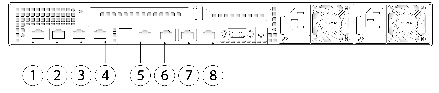
Figure 9-1 shows the rear panel ports of the Cisco S390 Web Security Appliance.
Figure 9-1 Rear Panel Ports of Cisco S390 Web Security Appliances
Using Status LEDs and Buttons for Maintenance
This section describes the location and meaning of LEDs and buttons and includes the following topics:
Front Panel LEDs
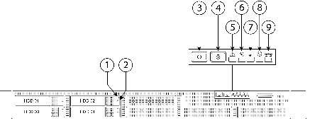
Figure 9-2 shows the front panel LEDs. Table 9-1 defines the LED states.
Figure 9-2 Cisco S390 Web Security Appliance Front Panel LEDs
|
|
|
||
|
|
|
||
|
|
|
||
|
|
|
||
|
|
|
 Power supply redundancy is lost.
Rear Panel LEDs and Buttons
The rear panel has the following LEDs and buttons that can be used to maintain the appliance:
- Power supply AC status LED—Located on the bottom left of each power supply.
- Data/Management port link speed LED—Located to the left of each Data or Management port.
- Data/Management port link status LED—Located to the right of each Data or Management port.
- Unit Identification button/LED—Located to the right of the VGA video port (DB-15).
Table 9-2 defines the LED states.
|
|
|
|---|---|
Summary of Features
Table 9-3 lists the features of the S390 Web Security Appliance.
 フィードバック