Optimizing Your ASAv Deployment
The Cisco Adaptive Security Virtual Appliance (ASAv) brings full firewall functionality to virtualized environments to secure data center traffic and multitenant environments. You can manage and monitor the ASAv using ASDM or CLI.
 Important |
For optimum performance you should be running ASA Version 9.13.(1) or greater. For the latest ASAv Getting Started Guide see the Cisco Adaptive Security Virtual Appliance (ASAv) support page. |
Licensing for the ASAv
The ASAv uses Cisco Smart Software Licensing. For complete information, see Smart Software Licensing (ASAv, ASA on Firepower).
Note |
You must install a smart license on the ASAv. Until you install a license, throughput is limited to 100 Kbps so you can perform preliminary connectivity tests. A smart license is required for regular operation. |
Beginning with 9.13(1), any ASAv license can be used on any supported ASAv vCPU/memory configuration. This allows you to deploy an ASAv on a wide variety of VM resource footprints. Session limits for AnyConnect and TLS Proxy are determined by the ASAv platform entitlement installed rather than a platform limit tied to a model type.
See the following sections for information about ASAv licensing entitlements and resource specifications for the supported private and public deployment targets.
About Smart License Entitlements
Any ASAv license can be used on any supported ASAv vCPU/memory configuration. This allows you to run the ASAv on a wide variety of VM resource footprints. This also increases the number of supported AWS and Azure instances types. When configuring the ASAv VM, the maximum supported number of vCPUs is 8; and the maximum supported memory is 64GB RAM.
-
vCPUs―The ASAv supports 1 to 8 vCPUs.
-
Memory―The ASAv supports 2 GB to 64 GB of RAM.
Important
Beginning with 9.13(1), the minimum memory requirement for the ASAv is 2GB. If your current ASAv runs with less than 2GB of memory, you cannot upgrade to 9.13(1) from an earlier version without increasing the memory of your ASAv VM. You can also redeploy a new ASAv VM with version 9.13(1).
When deploying an ASAv with more than 1 vCPU, the minimum memory requirement for the ASAv is 4GB.
Session Limits for Licensed Features
Session limits for AnyConnect and TLS Proxy are determined by the installed ASAv platform entitlement tier, and enforced via a rate limiter. The following table summarizes the session limits based on the entitlement tier and rate limiter.
|
Entitlement |
AnyConnect Premium Peers |
Total TLS Proxy Sessions |
Rate Limiter |
|---|---|---|---|
|
Standard Tier, 100M |
50 |
500 |
150 Mbps |
|
Standard Tier, 1G |
250 |
500 |
1 Gbps |
|
Standard Tier, 2G |
750 |
1000 |
2 Gbps |
|
Standard Tier, 10G |
10,000 |
10,000 |
10 Gbps |
Platform Limits for Licensed Features
The session limits granted by an entitlement, as shown in the previous table, cannot exceed the session limits for the platform. The platform session limits are based on the amount of memory provisioned for the ASAv. The maximum ASAv VM dimensions are 8 vCPUs and 64 GB of memory.
|
Provisioned Memory |
AnyConnect Premium Peers |
Total TLS Proxy Sessions |
|---|---|---|
|
2 GB to < 8 GB |
250 |
500 |
|
8 GB to < 16 GB |
750 |
1000 |
|
16 GB - 64 GB |
10,000 |
10,000 |
ASAv Private Cloud Entitlements (VMware, KVM, Hyper-V)
Because any ASAv license can be used on any supported ASAv vCPU/memory configuration, you have greater flexibility when you deploy the ASAv in a private cloud environment (VMware, KVM, Hyper-V). Session limits for AnyConnect and TLS Proxy are determined by the installed ASAv platform entitlement tier, and enforced via a rate limiter.
The following table summarizes the session limits based on the entitlement tier for the ASAv deployed to a private cloud environment, with the enforced rate limiter.
Note |
The platform session limits are based on the amount of memory provisioned for the ASAv; see Table 2. |
|
RAM (GB) |
Entitlement Support* |
|||||
|---|---|---|---|---|---|---|
|
Min |
Max |
Standard Tier, 100M |
Standard Tier, 1G |
Standard Tier, 2G |
Standard Tier, 10G |
Standard Tier, 20G |
|
2 |
7.9 |
50/500/100M |
250/500/1G |
250/500/2G |
250/500/10G |
250/500/20G |
|
8 |
15.9 |
50/500/100M |
250/500/1G |
750/1000/2G |
750/1000/10G |
750/1000/20G |
|
16 |
31.9 |
50/500/100M |
250/500/1G |
750/1000/2G |
10K/10K/10G |
10K/10K/20G |
|
32 |
64 |
50/500/100M |
250/500/1G |
750/1000/2G |
10K/10K/10G |
20K/20K/20G |
|
*AnyConnect Sessions / TLS Proxy Sessions / Rate Limiter per entitlement/instance. |
||||||
ASAv Public Cloud Entitlements (AWS)
Because any ASAv license can be used on any supported ASAv vCPU/memory configuration, you can deploy the ASAv on a wide variety AWS instances types. Session limits for AnyConnect and TLS Proxy are determined by the installed ASAv platform entitlement tier, and enforced via a rate limiter.
The following table summarizes the session limits and rate limiter based on the entitlement tier for AWS instance types. See "About ASAv Deployment On the AWS Cloud" for a breakdown of the AWS VM dimensions (vCPUs and memory) for the supported instances.
|
Instance |
BYOL Entitlement Support* |
PAYG** |
|||
|---|---|---|---|---|---|
|
Standard Tier, 100M |
Standard Tier, 1G |
Standard Tier, 2G |
Standard Tier, 10G |
||
|
c5.xlarge |
50/500/100M |
250/500/1G |
750/1000/2G |
750/1000/10G |
750/1000 |
|
c5.2xlarge |
50/500/100M |
250/500/1G |
750/1000/2G |
10K/10K/10G |
10K/10K |
|
c4.large |
50/500/100M |
250/500/1G |
250/500/2G |
250/500/10G |
250/500 |
|
c4.xlarge |
50/500/100M |
250/500/1G |
250/500/2G |
250/500/10G |
250/500 |
|
c4.2xlarge |
50/500/100M |
250/500/1G |
750/1000/2G |
10K/10K/10G |
750/1000 |
|
c3.large |
50/500/100M |
250/500/1G |
250/500/2G |
250/500/10G |
250/500 |
|
c3.xlarge |
50/500/100M |
250/500/1G |
250/500/2G |
250/500/10G |
250/500 |
|
c3.2xlarge |
50/500/100M |
250/500/1G |
750/1000/2G |
10K/10K/10G |
750/1000 |
|
m4.large |
50/500/100M |
250/500/1G |
250/500/2G |
250/500/10G |
250/500 |
|
m4.xlarge |
50/500/100M |
250/500/1G |
250/500/2G |
250/500/10G |
10K/10K |
|
m4.2xlarge |
50/500/100M |
250/500/1G |
750/1000/2G |
10K/10K/10G |
10K/10K |
|
*AnyConnect Sessions / TLS Proxy Sessions / Rate Limiter per entitlement/instance. **AnyConnect Sessions / TLS Proxy Sessions. The Rate Limiter is not employed in PAYG mode. |
|||||
Pay-As-You-Go (PAYG) Mode
The following table summarizes the Smart Licensing entitlements for each tier for the hourly billing (PAYG) mode, which is based on the allocated memory.
|
RAM (GB) |
Hourly Billing Mode Entitlement |
|---|---|
|
2 GB to < 8 GB |
Standard Tier, 1G |
|
8 GB to < 16 GB |
Standard Tier, 2G |
|
16 GB - 64 GB |
Standard Tier, 10G |
ASAv Public Cloud Entitlements (Azure)
Because any ASAv license can be used on any supported ASAv vCPU/memory configuration, you can deploy the ASAv on a wide variety Azure instances types. Session limits for AnyConnect and TLS Proxy are determined by the installed ASAv platform entitlement tier, and enforced via a rate limiter.
The following table summarizes the session limits and rate limiter based on the entitlement tier for the Azure instance types. See "About ASAv Deployment On the Microsoft Azure Cloud" for a breakdown of the Azure VM dimensions (vCPUs and memory) for the supported instances.
Note |
Pay-As-You-Go (PAYG) Mode is currently not supported for the ASAv on Azure. |
|
Instance |
BYOL Entitlement Support* |
|||
|---|---|---|---|---|
|
Standard Tier, 100M |
Standard Tier, 1G |
Standard Tier, 2G |
Standard Tier, 10G |
|
|
D1, D1_v2DS1, DS1_v2 |
50/500/100M |
250/500/1G |
250/500/2G |
250/500/10G |
|
D2, D2_v2, DS2, DS2_v2 |
50/500/100M |
250/500/1G |
250/500/2G |
250/500/10G |
|
D3, D3_v2, DS3, DS3_v2 |
50/500/100M |
250/500/1G |
750/1000/2G |
750/1000/10G |
|
D4, D4_v2, DS4, DS4_v2 |
50/500/100M |
250/500/1G |
750/1000/2G |
10K/10K/10G |
|
D2_v3 |
50/500/100M |
250/500/1G |
750/1000/2G |
750/1000/10G |
|
D4_v3 |
50/500/100M |
250/500/1G |
750/1000/2G |
10K/10K/10G |
|
D8_v3 |
50/500/100M |
250/500/1G |
750/1000/2G |
10K/10K/10G |
|
F1, F1s |
50/500/100M |
250/500/1G |
250/500/2G |
750/1000/10G |
|
F2, F2s |
50/500/100M |
250/500/1G |
250/500/2G |
750/1000/10G |
|
F4, F4s |
50/500/100M |
250/500/1G |
750/1000/2G |
750/1000/10G |
|
F8, F8s |
50/500/100M |
250/500/1G |
750/1000/2G |
10K/10K/10G |
|
*AnyConnect Sessions / TLS Proxy Sessions / Rate Limiter per entitlement/instance. |
||||
ASAv and SR-IOV Interface Provisioning
Single Root I/O Virtualization (SR-IOV) allows multiple VMs running a variety of guest operating systems to share a single PCIe network adapter within a host server. SR-IOV allows a VM to move data directly to and from the network adapter, bypassing the hypervisor for increased network throughput and lower server CPU burden. Recent x86 server processors include chipset enhancements, such as Intel VT-d technology, that facilitate direct memory transfers and other operations required by SR-IOV.
The SR-IOV specification defines two device types:
-
Physical Function (PF)—Essentially a static NIC, a PF is a full PCIe device that includes SR-IOV capabilities. PFs are discovered, managed, and configured as normal PCIe devices. A single PF can provide management and configuration for a set of virtual functions (VFs).
-
Virtual Function (VF)—Similar to a dynamic vNIC, a VF is a full or lightweight virtual PCIe device that provides at least the necessary resources for data movements. A VF is not managed directly but is derived from and managed through a PF. One or more VFs can be assigned to a VM.
SR-IOV is defined and maintained by the Peripheral Component Interconnect Special Interest Group ( PCI SIG), an industry organization that is chartered to develop and manage the PCI standard. For more information about SR-IOV, see PCI-SIG SR-IOV Primer: An Introduction to SR-IOV Technology.
Provisioning SR-IOV interfaces on the ASAv requires some planning, which starts with the appropriate operating system level, hardware and CPU, adapter types, and adapter settings.
Guidelines and Limitations for SR-IOV Interfaces
The specific hardware used for ASAv deployment can vary, depending on size and usage requirements. Licensing for the ASAv explains the compliant resource scenarios that match license entitlement for the different ASAv platforms. In addition, SR-IOV Virtual Functions require specific system resources.
Host Operating System and Hypervisor Support
SR-IOV support and VF drivers are available for:
-
Linux 2.6.30 kernel or later
The ASAv with SR-IOV interfaces is currently supported on the following hypervisors:
-
VMware vSphere/ESXi
-
QEMU/KVM
-
AWS
Hardware Platform Support
Note |
You should deploy the ASAv on any server class x86 CPU device capable of running the supported virtualization platforms. |
This section describes hardware guidelines for SR-IOV interfaces. Although these are guidelines and not requirements, using hardware that does not meet these guidelines may result in functionality problems or poor performance.
A server that supports SR-IOV and that is equipped with an SR-IOV-capable PCIe adapter is required. You must be aware of the following hardware considerations:
-
The capabilities of SR-IOV NICs, including the number of VFs available, differ across vendors and devices.
-
Not all PCIe slots support SR-IOV.
-
SR-IOV-capable PCIe slots may have different capabilities.
Note
You should consult your manufacturer's documentation for SR-IOV support on your system.
-
For VT-d enabled chipsets, motherboards, and CPUs, you can find information from this page of virtualization-capable IOMMU supporting hardware. VT-d is a required BIOS setting for SR-IOV systems.
-
For VMware, you can search their online Compatibility Guide for SR-IOV support.
-
For KVM, you can verify CPU compatibility. Note that for the ASAv on KVM we only support x86 hardware.
Note
We tested the ASAv with the Cisco UCS C-Series Rack Server. Note that the Cisco UCS-B server does not support the ixgbe-vf vNIC.
Supported NICs for SR-IOV
CPUs
-
x86_64 multicore CPU
Intel Sandy Bridge or later (Recommended)
Note
We tested the ASAv on Intel's Broadwell CPU (E5-2699-v4) at 2.3GHz.
-
Cores
-
Minimum of 8 physical cores per CPU socket
-
The 8 cores must be on a single socket.
Note
CPU pinning is recommended to achieve full throughput rates on the ASAv50 and ASAv100; see Increasing Performance on ESXi Configurations and Increasing Performance on KVM Configurations.
-
BIOS Settings
SR-IOV requires support in the BIOS as well as in the operating system instance or hypervisor that is running on the hardware. Check your system BIOS for the following settings:
-
SR-IOV is enabled
-
VT-x (Virtualization Technology) is enabled
-
VT-d is enabled
-
(Optional) Hyperthreading is disabled
We recommend that you verify the process with the vendor documentation because different systems have different methods to access and change BIOS settings.
Limitations
Be aware of the following limitations when using ixgbe-vf interfaces:
-
The guest VM is not allowed to set the VF to promiscuous mode. Because of this, transparent mode is not supported when using ixgbe-vf.
-
The guest VM is not allowed to set the MAC address on the VF. Because of this, the MAC address is not transferred during HA like it is done on other ASA platforms and with other interface types. HA failover works by transferring the IP address from active to standby.
-
The Cisco UCS-B server does not support the ixgbe-vf vNIC.
ASAv on VMware Guidelines and Limitations
You can create and deploy multiple instances of the ASAv on an ESXi server. The specific hardware used for ASAv deployments can vary, depending on the number of instances deployed and usage requirements. Each virtual appliance you create requires a minimum resource allocation—memory, number of CPUs, and disk space—on the host machine.
Review the following guidelines and limitations before you deploy the ASAv.
ASAv on VMware ESXi System Requirements
Make sure to conform to the specifications below to ensure optimal performance. The ASAv has the following requirements:
-
The host CPU must be a server class x86-based Intel or AMD CPU with virtualization extension.
For example, ASAv performance test labs use as minimum the following: Cisco Unified Computing System™ (Cisco UCS®) C series M4 server with the Intel® Xeon® CPU E5-2690v4 processors running at 2.6GHz.
-
ASAv supports ESXi version 6.0, 6.5, and 6.7.
Recommended vNICs
The following vNICs are recommended in order of optimum performance.
-
i40e in PCI passthrough—Dedicates the server's physical NIC to the VM and transfers packet data between the NIC and the VM via DMA (Direct Memory Access). No CPU cycles are required for moving packets.
-
i40evf/ixgbe-vf—Effectively the same as above (DMAs packets between the NIC and the VM) but allows the NIC to be shared across multiple VMs. SR-IOV is generally preferred because it has more deployment flexibility. See Guidelines and Limitations
-
vmxnet3—This is a para-virtualized network driver that supports 10Gbps operation but also requires CPU cycles. This is the VMware default.
When using vmxnet3, you need to disable Large Receive Offload (LRO) to avoid poor TCP performance.
Performance Optimizations
To achieve the best performance out of the ASAv, you can make adjustments to the both the VM and the host. See Performance Tuning for the ASAv on VMware for more information.
-
NUMA—You can improve performance of the ASAv by isolating the CPU resources of the guest VM to a single non-uniform memory access (NUMA) node. See NUMA Guidelines for more information.
-
Receive Side Scaling—The ASAv supports Receive Side Scaling (RSS), which is a technology utilized by network adapters to distribute network receive traffic to multiple processor cores. Supported on Version 9.13(1) and later. See Multiple RX Queues for Receive Side Scaling (RSS) for more information.
-
VPN Optimization—See VPN Optimization for additional considerations for optimizing VPN performance with the ASAv.
OVF File Guidelines
The selection of the asav-vi.ovf or asav-esxi.ovf file is based on the deployment target:
-
asav-vi—For deployment on vCenter
-
asav-esxi—For deployment on ESXi (no vCenter)
-
The ASAv OVF deployment does not support localization (installing the components in non-English mode). Be sure that the VMware vCenter and the LDAP servers in your environment are installed in an ASCII-compatible mode.
-
You must set your keyboard to United States English before installing the ASAv and for using the VM console.
-
When the ASAv is deployed, two different ISO images are mounted on the ESXi hypervisor:
-
The first drive mounted has the OVF environment variables generated by vSphere.
-
The second drive mounted is the day0.iso.
Attention
You can unmoumt both drives after the ASAv virtual machine has booted. However, Drive 1 (with the OVF environment variables) will always be mounted every time the ASAv is powered off/on, even if Connect at Power On is unchecked.
-
Failover for High Availability Guidelines
For failover deployments, make sure that the standby unit has the same license entitlement; for example, both units should have the 2Gbps entitlement.
Important |
When creating a high availability pair using ASAv, it is necessary to add the data interfaces to each ASAv in the same order. If the exact same interfaces are added to each ASAv, but in different order, errors may be presented at the ASAv console. Failover functionality may also be affected. |
IPv6 Guidelines
You cannot specify IPv6 addresses for the management interface when you first deploy the ASAv OVF file using the VMware vSphere Web Client; you can later add IPv6 addressing using ASDM or the CLI.
vMotion Guidelines
-
VMware requires that you only use shared storage if you plan to use vMotion. During ASAv deployment, if you have a host cluster you can either provision storage locally (on a specific host) or on a shared host. However, if you try to vMotion the ASAv to another host, using local storage will produce an error.
Memory and vCPU Allocation for Throughput and Licensing
-
The memory allocated to the ASAv is sized specifically for the throughput level. Do not change the memory setting or any vCPU hardware settings in the Edit Settings dialog box unless you are requesting a license for a different throughput level. Under-provisioning can affect performance.
Note
If you need to change the memory or vCPU hardware settings, use only the values documented in Licensing for the ASAv. Do not use the VMware-recommended memory configuration minimum, default, and maximum values.
CPU Reservation
-
By default the CPU reservation for the ASAv is 1000 MHz. You can change the amount of CPU resources allocated to the ASAv by using the shares, reservations, and limits settings (Edit Settings > Resources > CPU). Lowering the CPU Reservation setting from 1000 Mhz can be done if the ASAv can perform its required purpose while under the required traffic load with the lower setting. The amount of CPU used by an ASAv depends on the hardware platform it is running on as well as the type and amount of work it is doing.
You can view the host’s perspective of CPU usage for all of your virtual machines from the CPU Usage (MHz) chart, located in the Home view of the Virtual Machine Performance tab. Once you establish a benchmark for CPU usage when the ASAv is handling typical traffic volume, you can use that information as input when adjusting the CPU reservation.
See the CPU Performance Enhancement Advice published by VMware for more information.
-
You can use the ASAv show vm and show cpu commands or the ASDM tab or the pane to view the resource allocation and any resources that are over- or under-provisioned.
Transparent Mode on UCS B Series Hardware Guidelines
MAC flaps have been observed in some ASAv configurations running in transparent mode on Cisco UCS B Series hardware. When MAC addresses appear from different locations you will get dropped packets.
The following guidelines help prevent MAC flaps when you deploy the ASAv in transparent mode in VMware environments:
-
VMware NIC teaming—If deploying the ASAv in transparent mode on UCS B Series, the Port Groups used for the Inside and Outside interfaces must have only 1 Active Uplink, and that uplink must be the same. You configure VMware NIC teaming in vCenter.
See the VMware documentation for complete information on how to configure NIC teaming.
-
ARP inspection—Enable ARP inspection on the ASAv and statically configure the MAC and ARP entry on the interface you expect to receive it on. See the Cisco ASA Series General Operations Configuration Guide for information about ARP inspection and how to enable it.
ASAv Unreachable After You Disconnect a CD/DVD Drive
You can connect and disconnect a CD/DVD drives to an ASAv virtual machine using the Edit Settings dialog box. You connect and disconnect the device from the VM Hardware panel.
Important |
We recommend that you DO NOT disconnect any of the CD/DVD drives on the ASAv, as this can cause the ASAv to become unreachable. |
Workaround
If the ASAv is in an unreachable state due to a disconnected CD/DVD drive, do the following:
-
Click the Monitor tab, then click Notifications.
-
Look for an alert that says: The guest operating system has locked the CD-ROM door and is probably using the CD-ROM, which can prevent the guest from recognizing media changes. If possible, eject the CD-ROM from inside the guest before disconnecting. Disconnect anyway and override the lock?
-
Acknowledge the alert. When prompted, choose Yes on the popup, then click OK.
-
The ASAv virtual machine should again be reachable.
Additional Guidelines and Limitations
-
If you are running ESXi 5.0, the vSphere Web Client is not supported for ASAv OVF deployment; use the vSphere client instead.
Performance Tuning for the ASAv on VMware
Increasing Performance on ESXi Configurations
You can increase the performance for an ASAv in the ESXi environment by tuning the ESXi host CPU configuration settings. The Scheduling Affinity option gives you control over how virtual machine CPUs are distributed across the host's physical cores (and hyperthreads if hyperthreading is enabled). By using this feature, you can assign each virtual machine to processors in the specified affinity set.
See the following VMware documents for more information:
-
The Administering CPU Resources chapter of vSphere Resource Management.
-
The vSphere Client online help.
NUMA Guidelines
Non-Uniform Memory Access (NUMA) is a shared memory architecture that describes the placement of main memory modules with respect to processors in a multiprocessor system. When a processor accesses memory that does not lie within its own node (remote memory), data must be transferred over the NUMA connection at a rate that is slower than it would be when accessing local memory.
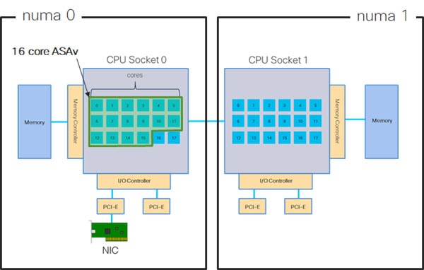
The x86 server architecture consists of multiple sockets and multiple cores within a socket. Each CPU socket along with its memory and I/O is referred to as a NUMA node. To efficiently read packets from memory, guest applications and associated peripherals (such as the NIC) should reside within the same node.
For optimum ASAv performance:
-
The ASAv VM must run on a single numa node. If a single ASAv is deployed so that is runs across 2 sockets, the perfomance will be significantly degraded.
-
An 8-core ASAv (Figure 1) requires that each socket on the host CPU have a minimum of 8 cores per socket. Consideration must be given to other VMs running on the server.
-
A 16-core ASAv (Figure 2) requires that each socket on the host CPU have a minimum of 16 cores per socket. Consideration must be given to other VMs running on the server.
-
The NIC should be on same NUMA node as ASAv VM.
The following figure shows a server with two CPU sockets with each CPU having 18 cores. The 8-core ASAv requires that each socket on the host CPU have a minimum of 8 cores.

The following figure shows a server with two CPU sockets with each CPU having 18 cores. The 16-core ASAv requires that each socket on the host CPU have a minimum of 16 cores.
More information about using NUMA systems with ESXi can be found in the VMware document vSphere Resource Management for your VMware ESXi version. To check for more recent editions of this and other relevant documents, see http://www.vmware.com/support/pubs
Multiple RX Queues for Receive Side Scaling (RSS)
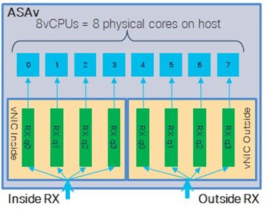
The ASAv supports Receive Side Scaling (RSS), which is a technology utilized by network adapters to distribute network receive traffic in parallel to multiple processor cores. For maximum throughput, each vCPU (core) must have its own NIC RX queue. Note that a typical RA VPN deployment might use a single inside/outside pair of interfaces.
Important |
You need ASAv Version 9.13(1) or greater to use multiple RX queues. |
For an 8-core VM with an inside/outside pair of interfaces, each interface will have 4 RX queues, as shown in Figure 1.
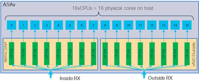
For a 16-core VM with an inside/outside pair of interfaces, each interface will have 8 RX queues, as shown in Figure 2.
The following table presents the ASAv's vNICs for VMware and the number of supported RX queues. See Recommended vNICs for descriptions of the supported vNICs.
|
NIC Card |
vNIC Driver |
Driver Technology |
Number of RX Queues |
Performance |
|---|---|---|---|---|
|
x710* |
i40e |
PCI Passthrough |
8 max |
PCI Passthrough offers the highest performance of the NICs tested. In passthrough mode the NIC is dedicated to the ASAv and is not an optimal choice for virtual. |
|
i40evf |
SR-IOV |
4 |
SR-IOV with the x710 NIC has lower throughput (~30%) than PCI Passthrough. i40evf on VMware has a maximum of 4 RX queues per i40evf. 8 RX queues are needed for maximum throughput on a 16 core VM. |
|
|
x520 |
ixgbe-vf |
SR-IOV |
4 |
The ixgbe-vf driver (in SR-IOV mode) has performance issues that are under investigation. |
|
ixgbe |
PCI Passthrough |
4 |
The ixgbe driver (in PCI Passthrough mode) has 4 RX queues. Performance is on par with i40evf (SR-IOV). |
|
|
N/A |
vmxnet3 |
Para-virtualized |
8 max |
Not recommended for ASAv100. |
|
N/A |
e1000 |
Not recommended by VMware. |
||
|
*The ASAv is not compatible with the 1.9.5 i40en host driver for the x710 NIC. Older or newer driver versions will work. See Identify NIC Drivers and Firmware Versions for information on ESXCLI commands to identify or verify NIC driver and firmware versions. |
||||
Identify NIC Drivers and Firmware Versions
If you need to identify or verify your specific firmware and driver version information, it is possible to find that data using ESXCLI commands.
-
To get a list of the installed NICs, SSH to the pertinent host and run the
esxcli network nic listcommand. This command should provide you with a record of devices and general information. -
After you have a list of the installed NICs, you can pull detailed configuration information. Run the
esxcli network nic getcommand specifying the name of the NIC necessary:esxcli network nic get –n <nic name>.
Note |
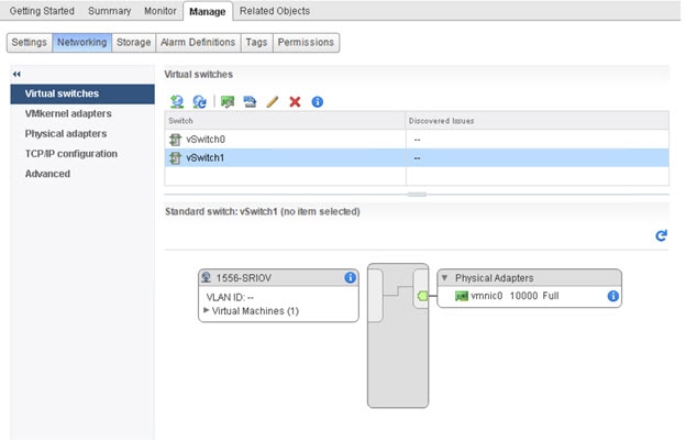
General network adapter information can also be viewed from the VMware vSphere Client. The adapter and driver are found under Physical Adapters within the Configure tab. |
VPN Optimization
These are some additional considerations for optimizing VPN performance with the ASAv.
-
IPSec has higher throughput than DTLS.
-
Cipher - GCM has about 2x the throughput of CBC.
SR-IOV Interface Provisioning
SR-IOV allows multiple VMs to share a single PCIe network adapter inside a host. SR-IOV defines these functions:
-
Physical function (PF)—PFs are full PCIe functions that include the SR-IOV capabilities. These appear as regular static NICs on the host server.
-
Virtual function (VF)—VFs are lightweight PCIe functions that help in data transfer. A VF is derived from, and managed through, a PF.
VFs are capable of providing up to 10 Gbps connectivity to ASAv virtual machines within a virtualized operating system framework. This section explains how to configure VFs in a KVM environment. SR-IOV support on the ASAv is explained in ASAv and SR-IOV Interface Provisioning.
Guidelines and Limitations
Guidelines for SR-IOV Interfaces
VMware vSphere 5.1 and later releases support SR-IOV in an environment with specific configurations only. Some features of vSphere are not functional when SR-IOV is enabled.
In addition to the system requirements for the ASAv and SR-IOV as described in Guidelines and Limitations for SR-IOV Interfaces, you should review the Supported Configurations for Using SR-IOV in the VMware documentation for more information about requirements, supported NICs, availability of features, and upgrade requirements for VMware and SR-IOV.
This section shows various setup and configuration steps for provisioning SR-IOV interfaces on a VMware system. The information in this section was created from devices in a specific lab environment, using VMware ESXi 6.0 and vSphere Web Client, a Cisco UCS C Series server, and an Intel Ethernet Server Adapter X520 - DA2.
Limitations for SR-IOV Interfaces
When the ASAv is booted, be aware that SR-IOV interfaces can show up in reverse order when compared to the order presented in ESXi. This could cause interface configuration errors that result in a lack of network connectivity for a particular ASAv virtual machine.
 Caution |
It is important that you verify the interface mapping before you begin configuring the SR-IOV network interfaces on the ASAv. This ensures that the network interface configuration will apply to the correct physical MAC address interface on the VM host. |
Check the ESXi Host BIOS
To deploy the ASAv with SR-IOV interfaces on VMware, virtualization needs to be supported and enabled. VMware provides several methods of verifying virtualization support, including their online Compatibility Guide for SR-IOV support as well as a downloadable CPU identification utility that detects whether virtualization is enabled or disabled.
You can also determine if virtualization is enabled in the BIOS by logging into the ESXi host.
Procedure
| Step 1 |
Log in to the ESXi Shell using one of the following methods:
|
| Step 2 |
Enter a user name and password recognized by the host. |
| Step 3 |
Run the following command: Example:The output of the HV Support command indicates the type of hypervisor support available. These are the descriptions for the possible values: 0 - VT/AMD-V indicates that support is not available for this hardware. 1 - VT/AMD-V indicates that VT or AMD-V might be available but it is not supported for this hardware. 2 - VT/AMD-V indicates that VT or AMD-V is available but is currently not enabled in the BIOS. 3 - VT/AMD-V indicates that VT or AMD-V is enabled in the BIOS and can be used. Example:The value 3 indicates the virtualization is supported and enabled. |
What to do next
-
Enable SR-IOV on the host physical adapter.
Enable SR-IOV on the Host Physical Adapter
Use the vSphere Web Client to enable SR-IOV and set the number of virtual functions on your host. You cannot connect virtual machines to virtual functions until you do so.
Before you begin
-
Make sure you have an SR-IOV-compatible network interface card (NIC) installed; see Supported NICs for SR-IOV.
Procedure
| Step 1 |
In the vSphere Web Client, navigate to the ESXi host where you want to enable SR-IOV. |
||
| Step 2 |
On the Manage tab, click Networking and choose Physical adapters. You can look at the SR-IOV property to see whether a physical adapter supports SR-IOV. |
||
| Step 3 |
Select the physical adapter and click Edit adapter settings. |
||
| Step 4 |
Under SR-IOV, select Enabled from the Status drop-down menu. |
||
| Step 5 |
In the Number of virtual functions text box, type the number of virtual functions that you want to configure for the adapter.
|
||
| Step 6 |
Click OK. |
||
| Step 7 |
Restart the ESXi host. The virtual functions become active on the NIC port represented by the physical adapter entry. They appear in the PCI Devices list in the Settings tab for the host. |
What to do next
-
Create a standard vSwitch to manage the SR-IOV functions and configurations.
Create a vSphere Switch
Create a vSphere switch to manage the SR-IOV interfaces.
Procedure
| Step 1 |
In the vSphere Web Client, navigate to the ESXi host. |
| Step 2 |
Under Manage select Networking, and then select Virtual switches. |
| Step 3 |
Click the Add host networking icon, which is the green globe icon with the plus (+) sign. |
| Step 4 |
Select a Virtual Machine Port Group for a Standard Switch connection type and click Next. |
| Step 5 |
Choose New standard switch and click Next. |
| Step 6 |
Add physical network adapters to the new standard switch.
|
| Step 7 |
Enter a Network label for the SR-IOV vSwitch and click Next. |
| Step 8 |
Review your selections on the Ready to complete page, then click Finish. |
What to do next
-
Review the compatibility level of your virtual machine.
Upgrade the Compatibility Level for Virtual Machines
The compatibility level determines the virtual hardware available to the virtual machine, which corresponds to the physical hardware available on the host machine. The ASAv virtual machine needs to be at Hardware Level 10 or higher. This will expose the SR-IOV passthough feature to the ASAv. This procedure upgrades the ASAv to the latest supported virtual hardware version immediately.
For information about virtual machine hardware versions and compatibility, see the vSphere Virtual Machine Administration documentation.
Procedure
| Step 1 |
Log in to the vCenter Server from the vSphere Web Client. |
| Step 2 |
Locate the ASAv virtual machine you wish to modify.
|
| Step 3 |
Power off the selected virtual machine. |
| Step 4 |
Right-click on the ASAv and select . |
| Step 5 |
Click Yes to confirm the upgrade. |
| Step 6 |
Choose the ESXi 5.5 and later option for the virtual machines compatiblity. |
| Step 7 |
(Optional) Select Only upgrade after normal guest OS shutdown. The selected virtual machine is upgraded to the corresponding hardware version for the Compatibility setting that you chose, and the new hardware version is updated in the Summary tab of the virtual machine. |
What to do next
-
Associate the ASAv with a virtual function through an SR-IOV passthrough network adapter.
Assign the SR-IOV NIC to the ASAv
To ensure that the ASAv virtual machine and the physical NIC can exchange data, you must associate the ASAv with one or more virtual functions as SR-IOV passthrough network adapters. The following procedure explains how to assign the SR-IOV NIC to the ASAv virtual machine using the vSphere Web Client.
Procedure
| Step 1 |
Log in to the vCenter Server from the vSphere Web Client. |
| Step 2 |
Locate the ASAv virtual machine you wish to modify.
|
| Step 3 |
On the Manage tab of the virtual machine, select . |
| Step 4 |
Click Edit and choose the Virtual Hardware tab. |
| Step 5 |
From the New device drop-down menu, select Network and click Add. A New Network interface appears. |
| Step 6 |
Expand the New Network section and select an available SRIOV option. |
| Step 7 |
From the Adapter Type drop-down menu, select SR-IOV passthrough. |
| Step 8 |
From the Physical function drop-down menu, select the physical adapter that corresponds to the passthrough virtual machine adapter. |
| Step 9 |
Power on the virtual machine. |
When you power on the virtual machine, the ESXi host selects a free virtual function from the physical adapter and maps it to the SR-IOV passthrough adapter. The host validates all properties of the virtual machine adapter and the underlying virtual function.
ASAv on KVM Guidelines and Limitations
The specific hardware used for ASAv deployments can vary, depending on the number of instances deployed and usage requirements. Each virtual appliance you create requires a minimum resource allocation—memory, number of CPUs, and disk space—on the host machine.
Review the following guidelines and limitations before you deploy the ASAv.
ASAv on KVM System Requirements
Make sure to conform to the specifications below to ensure optimal performance. The ASAv has the following requirements:
-
The host CPU must be a server class x86-based Intel or AMD CPU with virtualization extension.
For example, ASAv performance test labs use as minimum the following: Cisco Unified Computing System™ (Cisco UCS®) C series M4 server with the Intel® Xeon® CPU E5-2690v4 processors running at 2.6GHz.
Recommended vNICs
The following vNICs are recommended in order of optimum performance.
-
i40e in PCI passthrough—Dedicates the server's physical NIC to the VM and transfers packet data between the NIC and the VM via DMA (Direct Memory Access). No CPU cycles are required for moving packets.
-
i40evf/ixgbe-vf—Effectively the same as above (DMAs packets between the NIC and the VM) but allows the NIC to be shared across multiple VMs. SR-IOV is generally preferred because it has more deployment flexibility. See
-
virtio—This is a para-virtualized network driver that supports 10Gbps operation but also requires CPU cycles.
Performance Optimizations
To achieve the best performance out of the ASAv, you can make adjustments to the both the VM and the host. See Performance Tuning for the ASAv on KVM for more information.
-
NUMA—You can improve performance of the ASAv by isolating the CPU resources of the guest VM to a single non-uniform memory access (NUMA) node. See NUMA Guidelines for more information.
-
Receive Side Scaling—The ASAv supports Receive Side Scaling (RSS), which is a technology utilized by network adapters to distribute network receive traffic to multiple processor cores. See Multiple RX Queues for Receive Side Scaling (RSS) for more information.
-
VPN Optimization—See VPN Optimization for additional considerations for optimizing VPN performance with the ASAv.
CPU Pinning
CPU pinning is required for the ASAv to function in a KVM environment; see Enable CPU Pinning.
Failover for High Availability Guidelines
For failover deployments, make sure that the standby unit has the same license entitlement; for example, both units should have the 2Gbps entitlement.
Important |
When creating a high availability pair using ASAv, it is necessary to add the data interfaces to each ASAv in the same order. If the exact same interfaces are added to each ASAv, but in different order, errors may be presented at the ASAv console. Failover functionality may also be affected. |
Prerequisites for the ASAv and KVM
-
Download the ASAv qcow2 file from Cisco.com and put it on your Linux host:
http://www.cisco.com/go/asa-software
Note
A Cisco.com login and Cisco service contract are required.
-
For the purpose of the sample deployment in this document, we are assuming you are using Ubuntu 18.04 LTS. Install the following packages on top of the Ubuntu 18.04 LTS host:
-
qemu-kvm
-
libvirt-bin
-
bridge-utils
-
virt-manager
-
virtinst
-
virsh tools
-
genisoimage
-
-
Performance is affected by the host and its configuration. You can maximize the throughput of the ASAv on KVM by tuning your host. For generic host-tuning concepts, see NFV Delivers Packet Processing Performance with Intel.
-
Useful optimizations for Ubuntu 18.04 include the following:
-
macvtap—High performance Linux bridge; you can use macvtap instead of a Linux bridge. Note that you must configure specific settings to use macvtap instead of the Linux bridge.
-
Transparent Huge Pages—Increases memory page size and is on by default in Ubuntu 18.04.
Hyperthread disabled—Reduces two vCPUs to one single core.
-
txqueuelength—Increases the default txqueuelength to 4000 packets and reduces drop rate.
-
pinning—Pins qemu and vhost processes to specific CPU cores; under certain conditions, pinning is a significant boost to performance.
-
-
For information on optimizing a RHEL-based distribution, see Red Hat Enterprise Linux 7 Virtualization Tuning and Optimization Guide.
-
For ASA software and ASAv hypervisor compatibility, see Cisco ASA Compatibility.
Performance Tuning for the ASAv on KVM
Increasing Performance on KVM Configurations
You can increase the performance for an ASAv in the KVM environment by changing settings on the KVM host. These settings are independent of the configuration settings on the host server. This option is available in Red Hat Enterprise Linux 7.0 KVM.
You can improve performance on KVM configurations by enabling CPU pinning.
Enable CPU Pinning
ASAv requires that you use the KVM CPU affinity option to increase the performance of the ASAv in KVM environments. Processor affinity, or CPU pinning, enables the binding and unbinding of a process or a thread to a central processing unit (CPU) or a range of CPUs, so that the process or thread will execute only on the designated CPU or CPUs rather than any CPU.
Configure host aggregates to deploy instances that use CPU pinning on different hosts from instances that do not, to avoid unpinned instances using the resourcing requirements of pinned instances.
Attention |
Do not deploy instances with NUMA topology on the same hosts as instances that do not have NUMA topology. |
To use this option, configure CPU pinning on the KVM host.
Procedure
| Step 1 |
In the KVM host environment, verify the host topology to find out how many vCPUs are available for pinning: Example: |
||
| Step 2 |
Verify the available vCPU numbers: Example: |
||
| Step 3 |
Pin the vCPUs to sets of processor cores: Example:The virsh vcpupin command must be executed for each vCPU on your ASAv. The following example shows the KVM commands needed if you have an ASAv configuration with four vCPUs and the host has eight cores: The host core number can be any number from 0 to 7. For more information, see the KVM documentation.
|
NUMA Guidelines
Non-Uniform Memory Access (NUMA) is a shared memory architecture that describes the placement of main memory modules with respect to processors in a multiprocessor system. When a processor accesses memory that does not lie within its own node (remote memory), data must be transferred over the NUMA connection at a rate that is slower than it would be when accessing local memory.
The x86 server architecture consists of multiple sockets and multiple cores within a socket. Each CPU socket along with its memory and I/O is referred to as a NUMA node. To efficiently read packets from memory, guest applications and associated peripherals (such as the NIC) should reside within the same node.
For optimum ASAv performance:
-
The ASAv VM must run on a single numa node. If a single ASAv is deployed so that is runs across 2 sockets, the perfomance will be significantly degraded.
-
An 8-core ASAv (Figure 1) requires that each socket on the host CPU have a minimum of 8 cores per socket. Consideration must be given to other VMs running on the server.
-
A 16-core ASAv (Figure 2) requires that each socket on the host CPU have a minimum of 16 cores per socket. Consideration must be given to other VMs running on the server.
-
The NIC should be on same NUMA node as ASAv VM.
The following figure shows a server with two CPU sockets with each CPU having 18 cores. The 8-core ASAv requires that each socket on the host CPU have a minimum of 8 cores.
The following figure shows a server with two CPU sockets with each CPU having 18 cores. The 16-core ASAv requires that each socket on the host CPU have a minimum of 16 cores.
NUMA Optimization
Optimally, the ASAv VM should run on the same numa node that the NICs are running on. To do this:
-
Determine which node the NICs are on by using "lstopo" to show a diagram of the nodes. Locate the NICs and take note to which node they are attached.
-
At the KVM Host, use
virsh listto find the ASAv. -
Edit the VM by:
virsh edit <VM Number>. -
Align ASAv on the chosen node. The following examples assume 18-core nodes.
Align onto Node 0:
<vcpu placement='static' cpuset='0-17'>16</vcpu>
<numatune>
    <memory mode='strict' nodeset='0'/>
</numatune>
Align onto Node 1:
<vcpu placement='static' cpuset='18-35'>16</vcpu> <numatune> <memory mode='strict' nodeset='1'/> </numatune> -
Save the .xml change and power cycle the ASAv VM.
-
To ensure your VM is running on the desired node, perform a
ps aux | grep <name of your ASAv VM>to get the process ID. -
Run
sudo numastat -c <ASAv VM Process ID>to see if the ASAv VM is properly aligned.
More information about using NUMA tuning with KVM can be found in the RedHat document 9.3. libvirt NUMA Tuning.
Multiple RX Queues for Receive Side Scaling (RSS)
The ASAv supports Receive Side Scaling (RSS), which is a technology utilized by network adapters to distribute network receive traffic in parallel to multiple processor cores. For maximum throughput, each vCPU (core) must have its own NIC RX queue. Note that a typical RA VPN deployment might use a single inside/outside pair of interfaces.
Important |
You need ASAv Version 9.13(1) or greater to use multiple RX queues. For KVM, the libvirt version needs to be a minimum of 1.0.6. |
For an 8-core VM with an inside/outside pair of interfaces, each interface will have 4 RX queues, as shown in Figure 1.
For a 16-core VM with an inside/outside pair of interfaces, each interface will have 8 RX queues, as shown in Figure 2.
The following table presents the ASAv's vNICs for KVM and the number of supported RX queues. See Recommended vNICs for descriptions of the supported vNICs.
|
NIC Card |
vNIC Driver |
Driver Technology |
Number of RX Queues |
Performance |
|---|---|---|---|---|
|
x710 |
i40e |
PCI Passthrough |
8 maximum |
PCI Passthrough and SR-IOV modes for the x710 offer the best performance. SR-IOV is typically preferred for virtual deployments because the NIC can be shared across multiple VMs. |
|
i40evf |
SR-IOV |
8 |
||
|
x520 |
ixgbe |
PCI Passthrough |
4 |
The x520 NIC performs 10 to 30% lower than the x710. PCI Passthrough and SR-IOV modes for the x520 offer similar performance. SR-IOV is typically preferred for virtual deployments because the NIC can be shared across multiple VMs. |
|
ixgbe-vf |
SR-IOV |
4 |
||
|
N/A |
virtio |
Para-virtualized |
8 maximum |
Not recommended for ASAv100. For other deployments, see Enable Multiqueue Support for Virtio on KVM. |
Enable Multiqueue Support for Virtio on KVM
The following example shows to configure the number of Virtio NIC RX queues to 4 using virsh to edit the libvirt xml:
<interface type='bridge'>
 <mac address='52:54:00:43:6e:3f'/>
 <source bridge='clients'/>
 <model type='virtio'/>
 <driver name='vhost' queues='4'/>
 <address type='pci' domain='0x0000' bus='0x00' slot='0x04' function='0x0'/>
</interface>
Important |
The libvirt version needs to be a minimum of 1.0.6 to support multiple RX queues. |
VPN Optimization
These are some additional considerations for optimizing VPN performance with the ASAv.
-
IPSec has higher throughput than DTLS.
-
Cipher - GCM has about 2x the throughput of CBC.
SR-IOV Interface Provisioning
SR-IOV allows multiple VMs to share a single PCIe network adapter inside a host. SR-IOV defines these functions:
-
Physical function (PF)—PFs are full PCIe functions that include the SR-IOV capabilities. These appear as regular static NICs on the host server.
-
Virtual function (VF)—VFs are lightweight PCIe functions that help in data transfer. A VF is derived from, and managed through, a PF.
VFs are capable of providing up to 10 Gbps connectivity to ASAv virtual machines within a virtualized operating system framework. This section explains how to configure VFs in a KVM environment. SR-IOV support on the ASAv is explained in ASAv and SR-IOV Interface Provisioning.
Requirements for SR-IOV Interface Provisioning
If you have a physical NIC that supports SR-IOV, you can attach SR-IOV-enabled VFs, or Virtual NICs (vNICs), to the ASAv instance. SR-IOV also requires support in the BIOS as well as in the operating system instance or hypervisor that is running on the hardware. The following is a list of general guidelines for SR-IOV interface provisioning for the ASAv running in a KVM environment:
-
You need an SR-IOV-capable physical NIC in the host server; see Guidelines and Limitations for SR-IOV Interfaces.
-
You need virtualization enabled in the BIOS on your host server. See your vendor documentation for details.
-
You need IOMMU global support for SR-IOV enabled in the BIOS on your host server. See your hardware vendor documentation for details.
Modify the KVM Host BIOS and Host OS
This section shows various setup and configuration steps for provisioning SR-IOV interfaces on a KVM system. The information in this section was created from devices in a specific lab environment, using Ubuntu 14.04 on a Cisco UCS C Series server with an Intel Ethernet Server Adapter X520 - DA2.
Before you begin
-
Make sure you have an SR-IOV-compatible network interface card (NIC) installed.
-
Make sure that the Intel Virtualization Technology (VT-x) and VT-d features are enabled.
Note
Some system manufacturers disable these extensions by default. We recommend that you verify the process with the vendor documentation because different systems have different methods to access and change BIOS settings.
-
Make sure all Linux KVM modules, libraries, user tools, and utilities have been installed during the operation system installation; see Prerequisites for the ASAv and KVM.
-
Make sure that the physical interface is in the UP state. Verify with ifconfig <ethname>.
Procedure
| Step 1 |
Log in to your system using the “root” user account and password. |
||
| Step 2 |
Verify that Intel VT-d is enabled. Example:The last line indicates that VT-d is enabled. |
||
| Step 3 |
Activate Intel VT-d in the kernel by appending the intel_iommu=on parameter to the GRUB_CMDLINE_LINUX entry in the /etc/default/grub configuration file. Example:
|
||
| Step 4 |
Reboot the server for the iommu change to take effect. Example: |
||
| Step 5 |
Create VFs by writing an appropriate value to the sriov_numvfs parameter via the sysfs interface using the following format: To ensure that the desired number of VFs are created each time the server is power-cycled, you append the above command to the rc.local file, which is located in the /etc/rc.d/ directory. The Linux OS executes the rc.local script at the end of the boot process. For example, the following shows the creation of one VF per port. The interfaces for your particular setup will vary. Example: |
||
| Step 6 |
Reboot the server. Example: |
||
| Step 7 |
Verify that the VFs have been created using lspci. Example:
|
Assign PCI Devices to the ASAv
Once you create VFs, you can add them to the ASAv just as you would add any PCI device. The following example explains how to add an Ethernet VF controller to an ASAv using the graphical virt-manager tool.
Procedure
| Step 1 |
Open the ASAv click the Add Hardware button to add a new device to the virtual machine. 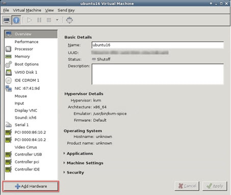 |
| Step 2 |
Click PCI Host Device from the Hardware list in the left pane. The list of PCI devices, including VFs, appears in the center pane. 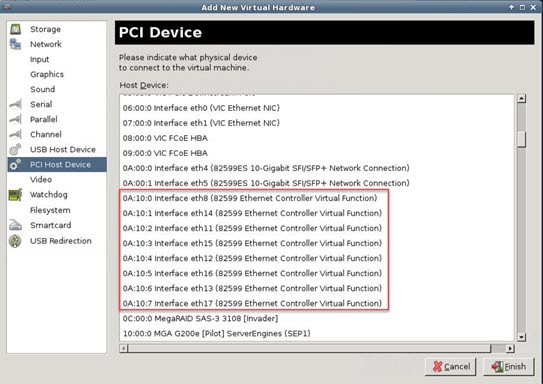 |
| Step 3 |
Select one of the available Virtual Functions and click Finish. The PCI Device shows up in the Hardware List; note the description of the device as Ethernet Controller Virtual Function. 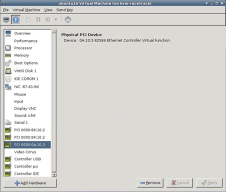 |
What to do next
-
Use the show interface command from the ASAv command line to verify newly configured interfaces.
-
Use the interface configuration mode on the ASAv to configure and enable the interface for transmitting and receiving traffic; see the Basic Interface Configuration chapter of the Cisco ASA Series General Operations CLI Configuration Guide for more information.
About ASAv Deployment On the AWS Cloud
The Cisco Adaptive Security Virtual Appliance (ASAv) runs the same software as physical Cisco ASAs to deliver proven security functionality in a virtual form factor. The ASAv can be deployed in the public AWS cloud. It can then be configured to protect virtual and physical data center workloads that expand, contract, or shift their location over time.
The ASAv support the following AWS instance types.
|
Instance |
Attributes |
Interfaces |
|
|---|---|---|---|
|
vCPUs |
Memory (GB) |
||
|
c5.xlarge |
4 |
8 |
4 |
|
c5.2xlarge |
8 |
16 |
4 |
|
c4.large |
2 |
3.75 |
3 |
|
c4.xlarge |
4 |
7.5 |
4 |
|
c4.2xlarge |
8 |
15 |
4 |
|
c3.large |
2 |
3.75 |
3 |
|
c3.xlarge |
4 |
7.5 |
4 |
|
c3.2xlarge |
8 |
15 |
4 |
|
m4.large |
2 |
4 |
3 |
|
m4.xlarge |
4 |
16 |
4 |
|
m4.2xlarge |
8 |
32 |
4 |
You create an account on AWS, set up the ASAv using the AWS Wizard, and chose an Amazon Machine Image (AMI). The AMI is a template that contains the software configuration needed to launch your instance.
Important |
The AMI images are not available for download outside of the AWS environment. |
Performance Tuning for the ASAv on AWS
VPN Optimization
The AWS c5 instances offer much higher performance than the older c3, c4, and m4 instances. The approximate RA VPN throughput (DTLS using 450B TCP traffic with AES-CBC encryption) on the c5 instance family should be:
-
0.5Gbps on c5.large
-
1Gbps on c5.xlarge
-
2Gbps on c5.2xlarge
 Feedback