Screw Replacement Procedure of Itron RIVA CAM Module on IR8140 Router
Overview
The procedure provided in this document is to establish the alternate procedure for replacing the alignment pin and lock washer with screw in Cisco IR8140 router.
 Note |
This procedure should be implemented only by Itron, for the RIVA CAM module installed on the IR8140 router. Any other parties using this procedure may cause damage to your product and wave the warranty. |
-
Alignment pin is interfering with the CAM module shield.
-
Alignment pin and lock washer needs to be replaced with the screw.
-
A proper procedure needs to be formulated to avoid and mitigate the failure modes.
Components Used
The following components are used in this procedure:
-
CISCO IR8140, main unit
-
420-1207-00 - M3.5 X 0.6, Length 8 mm – Torx screw – with nylon patch
-
Magnetic retriever – McMaster carr P#- 7385A44 or similar
-
6-inch-long T-10 Torx driver – McMaster car -p#-7396A52 or similar
-
Torque driver calibrated to 8-10 in.lbs
-
3/16 Standard socket
Screw Replacement Alternate Procedure
You should follow this procedure carefully to replace the alignment pin and washer with the screw.
|
Step No. |
Step Description |
Failure Mode |
Remarks |
|---|---|---|---|
|
1 |
Place the IR8140 in the fixture. (In horizontal orientation) 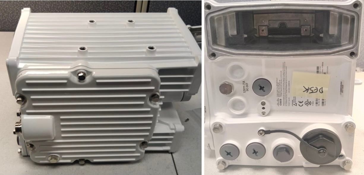
|
— |
— |
|
2 |
Use 3/16 socket driver as shown to remove the alignment pin and washer. The washer is intended to come off with the alignment pin. 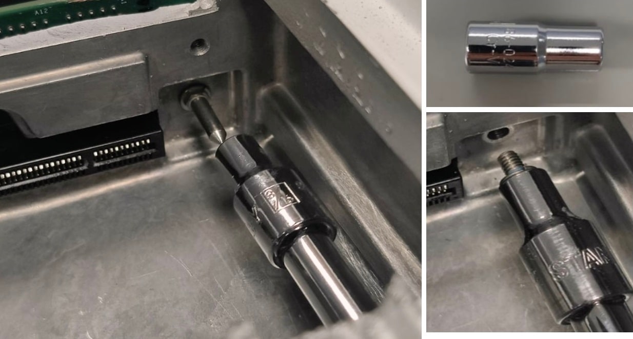
|
The socket might hit the connector in the slot. |
|
|
3 |
Check to see the washer is removed. If not, use a magnetic retriever to remove the washer. 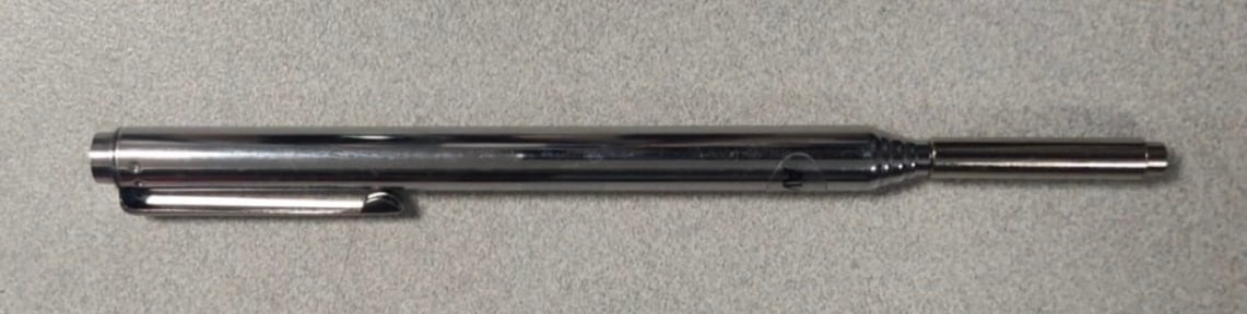
|
Washer remains in the cavity. |
Make sure the washer is removed. |
|
4 |
Carefully set the alignment pin and washer aside and discard these components. |
The components accidentally fall into the IR8140 cavity. |
Carefully discard these components. |
|
5 |
Use Torx screwdriver to assemble the screw inside the cavity to 8-10 in.lbs torque. 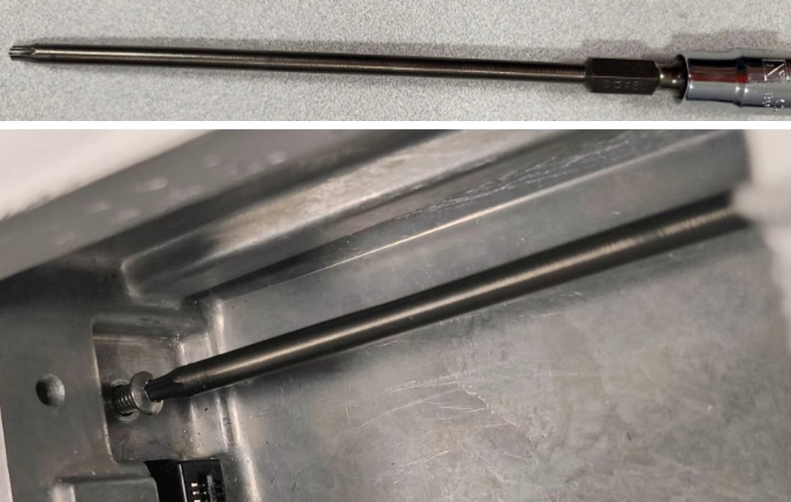
|
|
Check whether the screw is properly assembled and seated. |
|
6 |
Inspect whether the assembly is properly done. 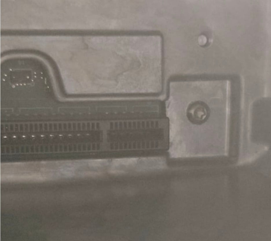
|
|
|
 Feedback