About Installing and Removing Cards and Associated Components
This section contains some general information about installing and removing cards, PLIMs, and associated components.
Guidelines for Card Installation and Removal
Guidelines for card installation and removal include the following:
- Online (in-service) insertion and removal (OIR) is supported, enabling you to remove and install cards while the router is operating. OIR is seamless to users on the network, maintains all routing information, and ensures session preservation. You do not need to notify the software or reset the power. You have the option of using the Cisco IOS XR shutdown command before removing a card.
 Note |
OIR removes power to a specific slot before the switch fabric card is replaced. The power remains on for all other slots. |
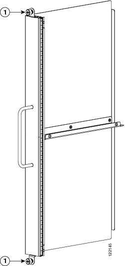
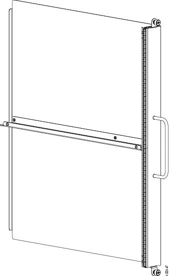
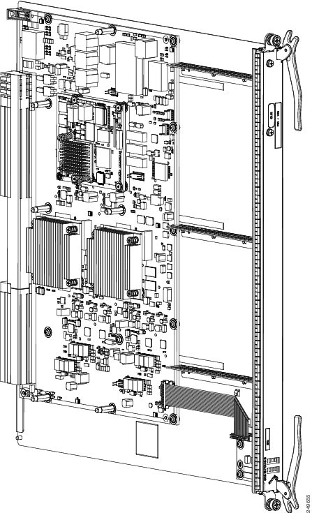
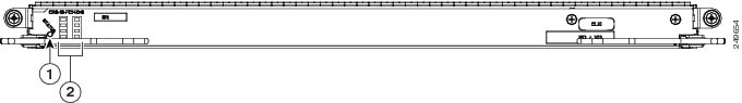
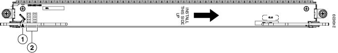
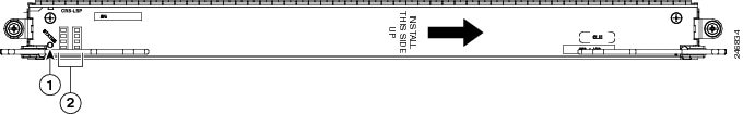
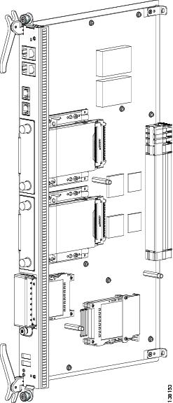
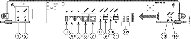
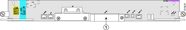
- The different cards and PLIMs in the LCC are all attached to the chassis itself using a pair of ejector levers and captive screws. The two ejector levers release the card or PLIM from its midplane connector. The exact locations of the ejector levers and captive screws vary slightly from card to card, but are, in general, in the same locations: on the upper and bottom ends of the faceplate of the card. The following figure shows the locations of the ejector levers and captive screws (on a modular services card (MSC)).

|
1 |
Captive screw |
2 |
Ejector lever |
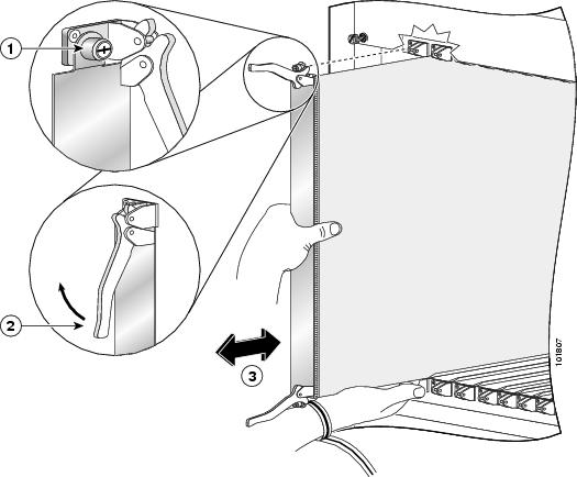
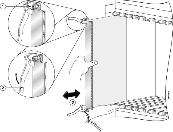
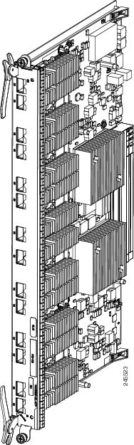
The following figure shows how to operate the ejector levers. Be sure to operate both levers simultaneously.
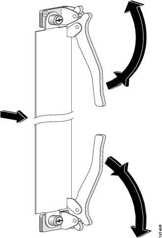
 Caution |
When you remove a card, always use the ejector levers to ensure that the connector pins disconnect from the midplane in the sequence expected by the router. |
- You should install
the cards in the following order during the chassis initial installation
process:
- Always install cards in the empty slots first from one side to the other. The chassis is shipped with all slots either containing impedance carriers or covered by slot covers to help maintain chassis stiffness and ensure that the chassis is undamaged during shipment. See the next section.
- Install the route processor (RP) cards first, the left one before the right one. Tighten the screws only after fully inserting both RP cards.
- Install the LCC fan controller cards in the same manner.
- Install the switch fabric cards in the same manner, one shelf at a time.
- For an MSC, FP, or LSP line card or a PLIM, remove one impedance carrier, install a functional board and tighten the screw, and then repeat the process until all line cards and PLIMs have been installed.
For information about the slot numbers, see Chassis Slot Numbers section.
Caution |
The router may indicate a hardware failure if you do not follow proper procedures. Remove or install only one card at a time. Allow at least 15 seconds for the router to complete the preceding tasks before removing or installing another card. |
About Impedance Carriers and Slot Covers
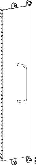
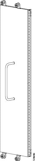
When shipped, some slots in the chassis may contain impedance carriers or are covered by slot covers to help ensure that the chassis is undamaged during shipment. Four different types of impedance carriers and slot covers exist for the four different sizes of slots in the chassis (see RP Slot Cover, Switch Fabric Slot Cover, PLIM Slot Impedance Carrier, and MSC Slot Impedance Carrier).
For further information on installing and removing the slot covers and impedance carriers, see Installing a Slot Cover, Removing a Slot Cover, Installing an Impedance Carrier, and Removing an Impedance Carrier.
About Hard Drives and PCMCIA Cards
Both replacement and additional optional hard drives and PCMCIA cards are available for both the RP and DRP cards.
The hard drive is an IDE hard drive used for gathering debugging information, such as core dumps from the RPs, DRPs, or line cards. The IDE hard drive is typically powered down and activated only when there is a need to store data. The drive is not vital to a functioning LCC and is optional.
Note |
Only the original route processor (RP) card uses a PCMCIA card. The performance route processor (PRP) card has a USB connector for using a flash drive. |
Note |
Core dumps are discoverable only through intervention with the LCC system software. |
Physically, the RP or DRP hard drive is a hot-pluggable PC board and sled-mounted drive with a connector interface that gets cleanly seated into a route processor card. In general, removal and replacement of this drive is not required.
The RP and DRP cards provide two PCMCIA flash slots, each card providing up to 1 GB of flash storage. One PCMCIA flash subsystem is accessible externally, is removable, and allows you to transfer images and configurations by plugging in a PCMCIA flash card. The other subsystem is fixed to the RP or DRP, not removable, and for permanent storage of configurations and images.
About Cable Management Brackets
The chassis includes a cable management system that organizes the interface cables entering and exiting the different cards, keeping them out of the way and free of sharp bends.
Caution |
Excessive bending of interface cables can cause damage to the cables. |
The LCC arrives with a midchassis and upper-chassis horizontal cable management bracket preinstalled on the front (PLIM) side of the chassis, with an optional upper-chassis horizontal cable management bracket available for the rear (MSC) side of the chassis.
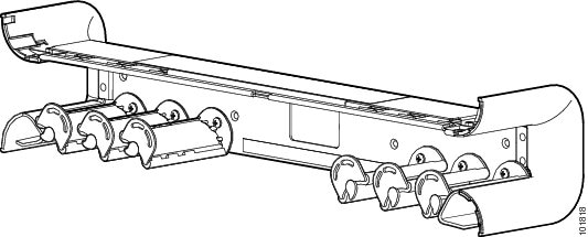
The following figure shows the midchassis cable management bracket.


 Feedback