Overview

This chapter provides a brief description of Cisco Carrier Routing System (CRS) 16-Slot Line Card Chassis (LCC) from the highest level.

This chapter includes the following topics:

  • Chassis Overview

  • Chassis Components

  • Chassis Slot Numbers

  • Chassis Footprint

  • Chassis Cable Management

  • Chassis Exterior Components

  • Chassis Cooling System

  • Chassis Power System

  • Safety Guidelines

  • Preventing Electrostatic Discharge

Chassis Overview

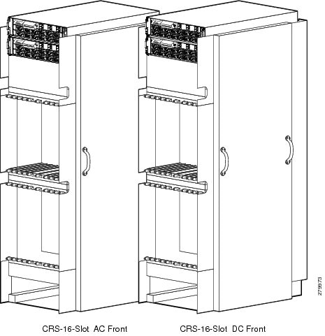
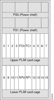
The 16 slots in the LCC can contain the following:

  • Modular services cards (MSCs)
  • Forwarding processor (FPs) cards
  • Label switch processor (LSP) cards

Note

MSCs, FPs, and LSPs are referred to as line cards.
  • Associated physical layer interface modules (PLIMs)
  • SPA Interface Processors (SIPs)

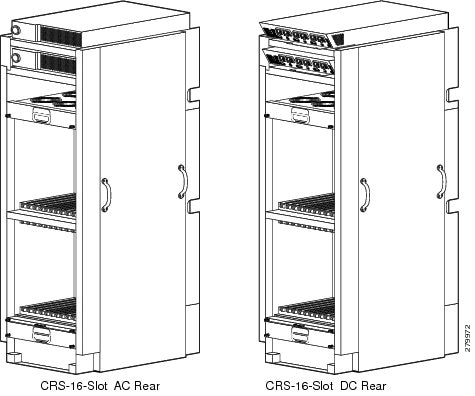
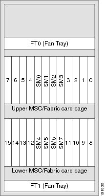
The LCC supports 40G, 140G, and 400G fabric cards, as follows:

  • The Cisco CRS-1 Carrier Routing System uses fabric cards designed for 40 G operation (CRS-16-FC/S or CRS-16-FC/M cards).
  • The Cisco CRS-3 Carrier Routing System uses fabric cards designed for 140G operation (CRS-16-FC140/S or CRS-16-FC140/M cards).
  • The Cisco CRS-X Carrier Routing System uses fabric cards designed for 200G operation (CRS-16-FC400/S or CRS-16-FC400/M cards in 200G mode).

A mixture of 40G, 140G, and 400G fabric cards is not supported except during migration.


Note

Throughout this document, the generic term Cisco CRS Carrier Routing system refers to the Cisco CRS-1, Cisco CRS-3, and Cisco CRS-X Carrier Routing Systems, unless otherwise specified.

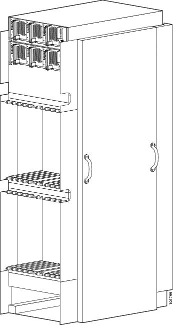
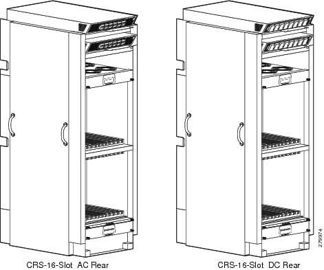
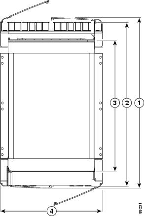
The LCC is secured to the floor and has locking front and rear doors (the front and rear doors are optional).


Note

For safety, the chassis must be secured following the installation procedures for the site.

Chassis Components

This section lists the main components of an LCC. It primarily identifies the components considered field-replaceable units (FRUs), but where additional detail is useful identifies subassemblies that are not field replaceable.

The LCC contains:

  • As many as 16 MSCs, FPs, LSPs, and 16 associated PLIMs. A line card (MSC, FP, or LSP) and a PLIM are an associated pair of cards that mate through the chassis midplane. The line card provides the forwarding engine for Layer 3 routing of user data being switched through the system, and the PLIM provides the physical interface and connectors for the user data.

Note

For a complete list of available PLIMs, consult your Cisco sales representative or visit http://www.cisco.com.
    • The MSC card is available in the following versions: CRS-MSC (end-of-sale), CRS-MSC-B, CRS-MSC-140G, and CRS-MSC-X /CRS-MSC-X-L.
    • The FP card is available in the following versions: CRS-FP140, CRS-FP-X/CRS-FP-X-L (200G mode).
    • The LSP card is: CRS-LSP.
  • Each line card can be associated with different types of PLIMs, which provide different interface speeds and technologies. Note the following:
    • The CRS-MSC-B card is compatible with both 40G CRS-1 and 140G CRS-3 fabric cards.
    • The CRS-MSC-140G card is only compatible with the 140G CRS-3 fabric card.
    • The CRS-MSC-X and CRS-MSC-X-L cards are compatible with the 400G CRS-X fabric card.
  • A chassis midplane. The midplane connects an MSC, FP, or LSP to its associated PLIM. The midplane design allows the MSC, FP, or LSP to be removed from the chassis without having to disconnect the cables that are attached to the associated PLIM. The midplane, which also distributes power, connects the MSCs, FPs, and LSPs to the switch fabric cards, and provides control plane interconnections, is not field replaceable by the customer.
  • Two route processor (RP) cards. The RPs supply the intelligence of the system by functioning as the LCC system controller.

A Performance Route Processor (PRP) is also available for the LCC. Two PRPs perform the same functions as two RPs, but provide enhanced performance for both route processing and system controller functionality.


Note

A chassis should not be populated with a mix of RP and PRP cards. Both route processor cards should be of the same type (either RP or PRP).
  • Eight switch fabric cards (SFCs).These fabric cards provide switch fabric components for the system. The switch fabric receives user data from one MSC, FP, or LSP and PLIM pair and performs the switching necessary to route the data to the appropriate egress MSC, FP, or LSP and PLIM pair.
    • As a single-shelf (standalone) system, the LCC contains switch fabric cards that provide all three stages of the three-stage Benes switch fabric.
    • As part of a multishelf system, the LCC contains S13 fabric cards that provide Stage 1 and Stage 3 of the switch fabric. S2 fabric cards in the Cisco CRS Fabric Card Chassis (FCC) provide Stage 2 of the fabric, and fabric cables connect the fabric cards to each other.

Note

The LCC supports either 40G fabric (FC/S cards), 140G fabric (FC-140/S cards), or 400G fabric (FC-400/S cards). An LCC with a mix of 40G, 140G, and 400G fabric cards is not a supported mode of operation. Such a mode is temporarily allowed only during the upgrade process.
  • Two fan controller cards. The cards vary the high-speed fans in the fan trays to adjust the airflow for ambient conditions.
  • Upper and lower fan trays. The trays push and pull air through the chassis. A removable air filter is located above the lower fan tray.
  • Two types of power systems are available: fixed configuration power and modular configuration power. Both power configurations use either AC or DC power and are fully redundant.

This figure shows a front view of an LCC with a fixed configuration AC power system installed. The front view of an LCC with a fixed configuration DC power system installed is similar.

Figure 1. LCC Front (PLIM) Side View - Fixed Configuration Power

This figure shows the rear view of an LCC with a fixed configuration AC and DC power system installed.

Figure 2. LCC Rear (MSC) Side View - Fixed Configuration Power

This figure shows the front view of an LCC with a modular configuration AC and DC power system installed.

Figure 3. LCC Front (PLIM) Side View - Modular Configuration Power

This figure shows the rear view of an LCC with a modular configuration AC and DC power system installed.

Figure 4. LCC Rear (MSC) Side View - Modular Configuration Power

Chassis Slot Numbers

This section identifies the locations and slot numbers for major cards and modules (primarily the field replaceable units) that plug into the chassis.

This figure shows the chassis slot numbers on the front (PLIM) side of the LCC.

Figure 5. LCC Front (PLIM) Side Slot Numbers—Fixed Configuration Power Shown

The components on the front (PLIM) side of the chassis include:

  • Upper power shelf (PS0)
  • Lower power shelf (PS1)
  • Upper PLIM card cage with eight PLIM slots (left to right: 0, 1, 2, 3 and 4, 5, 6, 7) spaced around two double-width fan controller card slots, FC0 and FC1. (These thicker-width slots accept only the two fan controllers.)
  • Lower PLIM card cage with eight PLIM slots (left to right: 8, 9, 10, 11 and 12, 13, 14, 15) and two double-width route processor card slots, RP0 and RP1. (These thicker-width slots accept only the RPs.)

The following figure shows the chassis slot numbers on the rear (MSC) side of the LCC.

Figure 6. Rear (MSC) Side Slot Numbers

The components on the rear (MSC) side of the chassis include:

  • Top fan tray (FT0)
  • Upper card cage, eight MSC slots (left to right: 7, 6, 5, 4 and 3, 2, 1, 0) spaced around four switch fabric card slots (SM0, SM1, SM2, and SM3)
  • Lower card cage, eight MSC slots (left to right: 15, 14, 13, 12 and 11, 10, 9, 8) spaced around four switch fabric card slots (SM4, SM5, SM6, and SM7)
  • Lower fan tray (FT1)

The MSC slot numbers are reversed from the PLIM slot numbers on the other side of the chassis. Because an MSC is associated and actually mates through the midplane with a PLIM, MSC slot 0 is on the far right side of the chassis looking at it from the rear (MSC) side; PLIM slot 0 is on the far left side of the chassis looking at it from the front (PLIM) side. MSC slot 0 and PLIM slot 0 mate with each other through the midplane, and so do all other MSC and PLIM slots (2 through 15).


Note

Any line card (MSC, FP, or LSP) can be inserted into an MSC slot.

Chassis Footprint

For each installation site, Cisco provides one aluminum drill template of an LCC footprint, showing the location of the hole pattern needed to be drilled into the floor.

Cisco can also provide a mylar template of the LCC footprint, including its door swings and the clearance needed to remove and replace components, that can be used for planning the aisle space required for the installation and maintenance of an LCC.

This figure is a top view of the LCC footprint (with optional front and rear cosmetics installed).

Figure 7. Top View of LCC

1

Depth of LCC with doors attached and closed, 40.2 in. (102.2 cm)

2

Depth of front cable management to rear cable management, excluding doors, 38.3 in. (97.2 cm)

3

From front surface to rear surface of chassis, excl. cable management and doors, 32.8 in. (83.2 cm)

4

Width of chassis, 23.5 in. (59.8 cm).


Note

Because no external switch fabric interconnection cabling exists on the single LCC, the rear door is optional.

Chassis Cable Management

The LCC has cable management features for both the front (PLIM) and rear (MSC) sides of the chassis. The PLIM side has horizontal cable management features above both card cages. The front horizontal cable management trays have a special telescoping feature that allows them to be extended when the chassis is upgraded with higher-density cards. This extension feature also helps when installing the cables in the chassis.


Note

The front cosmetic doors need to be removed from the chassis when the telescoping feature is in use.

The MSC side of the chassis has one cable management system above the lower card cage (in the middle of the chassis). These rear cable management trays are not telescoping because there is a preset amount of fiber cabling to be managed.

Chassis Exterior Components

The LCC also includes front and rear locking doors, bezels, and side panels. The front and rear doors are optional in the standalone system. The cosmetic components are shipped in a separate package and must be installed on the LCC during system installation.

Chassis Cooling System

The LCC cooling system includes the components and control system that draw ambient air through the system to dissipate heat and keep the system operating in a desired temperature range. The complete LCC cooling system includes:

  • Two fan trays
  • Two fan controller cards
  • Temperature sensors distributed on cards and modules in the chassis
  • Operating software that controls the cooling system
  • Air filter
  • Inlet and outlet air vents and bezels
  • Impedance carriers for empty chassis slots
  • Power module cooling fans

The airflow through the LCC is controlled by a push-pull configuration. As shown in the figure below, ambient air flows in at the bottom front (PLIM) side and up through the card cages until it exhausts at the top rear (MSC) side of the LCC. The bottom fan tray pulls ambient air in from the bottom front of the chassis; the top fan tray pushes warm air out the back of the chassis. The power modules in the power shelves have their own self-contained cooling fans.

A replaceable air filter is positioned above the lower fan tray. How often the air filter should be replaced depends on the facility environment. In a dirty environment, or when you start getting frequent temperature alarms, you should always check the intake grills for debris, and then check the air filter to see if it needs replacement.

Before removing the air filter for replacement, you should have a spare filter on hand; then, when you remove the dirty filter, install the spare filter in the chassis.

Figure 8. Airflow Through LCC

1

Front (PLIM) side of chassis

6

Power shelves (two installed)

2

Air intake

7

Air exhaust

3

Lower fan tray

8

Upper card cage

4

Air filter

9

Lower card cage

5

Upper fan tray

10

Rear (MSC) side of chassis

Chassis Power System

Two types of power systems are available for the LCC: fixed configuration power and modular configuration power. Both power systems can be powered by either AC or DC power.

The chassis power system takes the facility power and converts it to the DC voltage necessary to power chassis components. Both types of power system comprise:

  • Redundant AC or DC power shelves
  • Alarm modules, one per power shelf
  • Bus bar
  • Chassis midplane

Safety Guidelines

Before you perform any procedure in this document, review the safety guidelines in this section to avoid injuring yourself or damaging the equipment.


Note

Although power shelves may be installed or removed without powering down the system, for safety purposes we recommend that you power down the system before you install or remove a power shelf.

The following guidelines are for your safety and to protect equipment. The guidelines do not include all hazards. Be alert.


Note

Review the safety warnings listed in Regulatory Compliance and Safety Information for the Cisco CRS Carrier Routing System before installing, configuring, or troubleshooting any installed card.
  • Never attempt to lift an object that might be too heavy for you to lift by yourself.
  • Keep the work area clear and dust free during and after installation. Do not allow dirt or debris to enter into any laser-based components.
  • Keep tools and router components away from walk areas.
  • Do not wear loose clothing, jewelry, and other items that could get caught in the router while working with PLIMs, MSCs, SFCs, and their associated components.
  • Use Cisco equipment in accordance with its specifications and product-usage instructions.
  • Do not work alone if potentially hazardous conditions exist.
  • Make sure your installation follows national and local electrical codes: in the United States, National Fire Protection Association (NFPA) 70, United States National Electrical Code; in Canada, Canadian Electrical Code, part I, CSA C22.1; in other countries, International Electrotechnical Commission (IEC) 60364, part 1 through part 7.
  • Connect only a DC power source that follows the safety extra-low voltage (SELV) requirements in UL/CSA/IEC/EN 60950-1 and AS/NZS 60590 to the DC-input power system.
  • Make sure that you have a readily accessible two-poled disconnect device incorporated in the fixed configuration wiring of a CRS configured with the DC-input power system.
  • Make sure that you provide short-circuit (overcurrent) protection as part of the building installation.

Preventing Electrostatic Discharge

Electrostatic discharge (ESD) damage, which can occur when electronic cards or components are improperly handled, results in complete or intermittent failures. We recommend use of an ESD-preventive strap whenever you handle network equipment or one of its components.

Following are guidelines for preventing ESD damage:

  • Always use an ESD-preventive wrist or ankle strap, and ensure that it makes good skin contact. Connect the equipment end of the connection cord to an ESD connection socket on the router or to a bare metal surface on the chassis.
  • Handle a card by its ejector levers, when applicable, or its metal carrier only; avoid touching the board or connector pins.
  • Place a removed card board side up on an antistatic surface or in a static-shielding bag. If you plan to return the component to the factory, immediately place it in a static-shielding bag.
  • Avoid contact between the card and clothing. The wrist strap protects the board from only ESD voltage on the body; ESD voltage on clothing can still cause damage.