Appendix A: Cable Specifications and Information
Available Languages
Table Of Contents
Cable Specifications and Information
Console and Auxiliary Port Cables and Pinouts
Console Port to ASCII Terminal
Alternative Connections to Terminal and Modem
Serial Cable Assemblies and Pinouts
Fast Ethernet Port Pinouts (RJ-45)
T1/E1-WAN and T1/E1-PBX Port Pinouts (RJ-48C/CA81A)
Analog Voice Multiport Pinouts (RJ-21X/CA21A)
Synchronous Serial Interface Cable Information
Cable Specifications and Information
This appendix provides the connector and pinout information you need for making or purchasing cables used with Cisco IADs and contains the following sections:
•
Console and Auxiliary Port Cables and Pinouts
•
•
•
•
•
The following list shows you which table to see for pinout information:
Console Port to ASCII Terminal—Cable Pinouts (RJ-45 to DB-25)
To order cables from Cisco, see the "Obtaining Technical Assistance" section on page xviii.
Console and Auxiliary Port Cables and Pinouts
Your Cisco IAD comes with the cable and adapters you need to connect a PC, an ASCII terminal, or a modem to your Cisco IAD. The cable kit includes:
•
•
•
The following illustrations and tables provide cable pinout information:
•
•
•
The console port is configured as data communications equipment (DCE); the auxiliary port is configured as data terminal equipment (DTE). Both are asynchronous serial ports and use RJ-45 connectors.
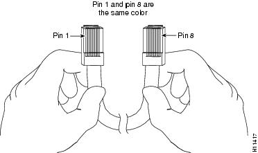
Identifying a Rollover Cable
You can identify a rollover cable by holding the plugs side by side, with the tab at the back and comparing the modular plugs at the two ends of the cable. The wire connected to the pin on the outside of the left plug should be the same color as the wire connected to the pin on the outside of the right plug. (See Figure A-1.)
If your cable comes from Cisco Systems, pin 1 is white on one plug, and pin 8 is white on the opposite plug. (A rollover cable reverses the wire connections at the opposite ends: 1 to 8, 2 to 7, 3 to 6, 4 to 5, 5 to 4, 6 to 3, 7 to 2, and 8 to 1.)
Figure A-1 Identifying a Rollover Cable
Console Port to PC
Figure A-2 shows the RJ-45-to-RJ-45 rollover cable assembly and the RJ-45-to-DB-9 female DTE adapter (labeled TERMINAL); Table A-1 lists the pinouts.
Figure A-2 Console Port to PC—Cable and Adapter
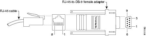
Table A-1 Console Port to PC—Cable Pinouts (RJ-45 to DB-9)
RTS
11
8
8
8
CTS
DTR
2
7
7
6
DSR
TxD
3
6
6
2
RxD
GND
4
5
5
5
GND
GND
5
4
4
5
GND
RxD
6
3
3
3
TxD
DSR
7
2
2
4
DTR
CTS
81
1
1
7
RTS
1 Pin 1 is connected to pin 8 inside the Cisco IAD.
Console Port to ASCII Terminal
Figure A-3 shows the RJ-45-to-RJ-45 rollover cable assembly and the RJ-45-to-DB-25 female DTE adapter (labeled TERMINAL); Table A-2 lists the pinouts.
Figure A-3 Console Port to ASCII Terminal—Cable and Adapter
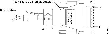
Table A-2 Console Port to ASCII Terminal—Cable Pinouts (RJ-45 to DB-25)
RTS
11
8
8
5
CTS
DTR
2
7
7
6
DSR
TxD
3
6
6
3
RxD
GND
4
5
5
7
GND
GND
5
4
4
7
GND
RxD
6
3
3
2
TxD
DSR
7
2
2
20
DTR
CTS
81
1
1
4
RTS
1 Pin 1 is connected to pin 8 inside the Cisco IAD.
Auxiliary Port to Modem
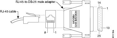
Figure A-4 shows the RJ-45-to-RJ-45 rollover cable assembly and the RJ-45-to-DB-25 male DCE adapter (labeled MODEM); Table A-3 lists the pinouts.
Figure A-4 Auxiliary Port to Modem—Cable and Adapter
Alternative Connections to Terminal and Modem
Your Cisco IAD ships with an RJ-45-to-RJ-45 rollover cable and two adapters for connection to a PC, a terminal, or a modem. If you want to use an RJ-45 straight-through cable or other adapters, see Table A-4 for usable cable and adapter combinations.
Table A-4 Alternative Terminal and Modem Connections
Console port to PC
Straight-through
DCE, DB-9 female
Auxiliary port to modem
Rollover1
DCE2 , DB-25, male
Straight-through
DTE2, DB-25, male
1 An octal cable or RJ-45 breakout cable is equivalent to a rollover cable.
2 Modify the DB-25 adapter by removing the wire in pin 6 and placing it in the pin 8 position.
Serial Cable Assemblies and Pinouts
The following illustrations and tables provide assembly drawings and pinouts for the EIA/TIA-530 DCE, EIA/TIA-232, EIA/TIA-449, V.35, and X.21 DTE and DCE cables. These cables are used with the synchronous serial port, labeled SERIAL 0.

Note
EIA/TIA-530
Figure A-6 shows the EIA/TIA-530 serial cable assembly; Table A-7 lists the DTE pinouts; Table A-8 lists the DCE pinouts. Arrows indicate signal direction.
Figure A-5 EIA-530 Serial Cable Assembly
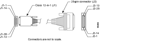
Table A-5 EIA/TIA-530 DTE Cable Pinouts (Cisco 12-in-1 to DB-25) 1
J1-21
J1-23
J1-24MODE_2
MODE_0
MODE_DCELocal connections
-
-
-
-
-
Shield
-
J2-1
Shield GND
J1-1
J1-14O_TxD/RxD+
O_TxD/RxD-Twisted pair no. 5
——>
——>J2-2
J2-14BA(A), TxD+
BA(B), TxD-J1-5
J1-18I_RxD/TxD+
I_RxD/TxD-Twisted pair no. 9
<——
<——J2-3
J2-16BB(A), RxD+
BB(B), RxD-J1-8
J1-9O_RTS/CTS+
O_RTS/CTS-Twisted pair no. 1
——>
——>J2-4
J2-19CA(A), RTS+
CA(B), RTS-J1-11
J1-10I_CTS/RTS+
I_CTS/RTS-Twisted pair no. 4
<——
<——J2-5
J2-13CB(A), CTS+
CB(B), CTS-J1-12
J1-25I_DSR/DTR+
I_DSR/DTR-Twisted pair no. 10
<——
—J2-6
CC(A), DSR+
AC; GNDJ1-6
J1-19IO_DCD/DCD+
IO_DCD/DCD-Twisted pair no. 11
<——
<——J2-8
J2-10CF(A), DCD+
CF(B), DCD-J1-3
J1-16IO_TxC/RxC+
IO_TxC/RxC-Twisted pair no. 7
<——
<——J2-15
J2-12DB(A), TxC+
DB(B), TxC-J1-4
J1-17I_RxC/TxCE+
I_RxC/TxCE-Twisted pair no. 8
<——
<——J2-17
J2-9DD(A), RxC+
DD(B), RxC-J1-13
J1-26O_LL/DCD
Circuit GNDTwisted pair no. 12
——>
—J2-18
J2-7LL
AB; GNDJ1-7
J1-20O_DTR/DSR+
O_DTR/DSR-Twisted pair no. 3
——>
—J2-20
J2-23CD(A), DTR+
AC; GNDJ1-2
J1-15O_TxCE/TxC+
O_TxCE/TxC-Twisted pair no. 6
——>
——>J2-24
J2-11DA(A), TxCE+
DA(B), TxCE--
-
Twisted pair no. 2
-
-
Not used
1 Any pin not referenced is not connected.
Table A-6 EIA/TIA-530 DCE Cable Pinouts (Cisco 12-in-1 to DB-25) 1
J1-21
J1-23MODE_2
MODE_0Local Connections
-
-
-
-
-
Shield
-
J2-1
Shield GND
J1-5
J1-18I_RxD/TxD+
I_RxD/TxD-Twisted pair no. 5
<——
<——J2-2
J2-14BA(A), TxD+
BA(B), TxD-J1-1
J1-14O_TxD/RxD+
O_TxD/RxD-Twisted pair no. 9
——>
——>J2-3
J2-16BB(A), RxD+
BB(B), RxD-J1-11
J1-10I_CTS/RTS+
I_CTS/RTS-Twisted pair no. 1
<——
<——J2-4
J2-19CA(A), RTS+
CA(B), RTS-J1-8
J1-9O_RTS/CTS+
O_RTS/CTS-Twisted pair no. 4
——>
——>J2-5
J2-13CB(A), CTS+
CB(B), CTS-J1-7
J1-20O_DTR/DSR+
O_DTR/DSR-Twisted pair no. 10
——>
——>J2-6
J2-22CC(A), DSR+
CC(B), DSR-J1-6
J1-19IO_DCD/DCD+
IO_DCD/DCD-Twisted pair no. 11
——>
——>J2-8
J2-10CF(A), DCD+
CF(B), DCD-J1-3
J1-16O_TxCE/TxC+
O_TxCE/TxC-Twisted pair no. 7
——>
——>J2-15
J2-12DB(A), TxC+
DB(B), TxC-J1-2
J1-15IO_TxC/RxC+
IO_TxC/RxC-Twisted pair no. 8
——>
——>J2-17
J2-9DD(A), RxC+
DD(B), RxC-J1-13
J1-26I_NIL/LL
Circuit GNDTwisted pair no. 12
<——
——J2-18
J2-7LL
AB; GNDJ1-12
J1-25I_DSR/DTR+
I_DSR/DTR-Twisted pair no. 3
<——
<——J2-20
J2-23CD(A), DTR+
AC; GNDJ1-4
J1-17I_RxC/TxCE+
I_RxC/TxCE-Twisted pair no. 6
<——
<——J2-24
J2-11DA(A), TxCE+
DA(B), TxCE--
-
Twisted pair no. 2
-
-
Not used
1 Any pin not referenced is not connected.
EIA/TIA-530A
Figure A-6 shows the EIA/TIA-530A serial cable assembly; Table A-7 lists the DTE pinouts; Table A-8 lists the DCE pinouts. Arrows indicate signal direction.
Figure A-6 EIA-530A Serial Cable Assembly
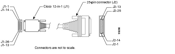
Table A-7 EIA/TIA-530A DTE Cable Pinouts (Cisco 12-in-1 to DB-25) 1
J1-21
J1-22
J1-24MODE_2
MODE_1
MODE_DCELocal connections
-
-
-
-
-
Shield
-
J2-1
Shield GND
J1-1
J1-14O_TxD/RxD+
O_TxD/RxD-Twisted pair no. 5
——>
——>J2-2
J2-14BA(A), TxD+
BA(B), TxD-J1-5
J1-18I_RxD/TxD+
I_RxD/TxD-Twisted pair no. 9
<——
<——J2-3
J2-16BB(A), RxD+
BB(B), RxD-J1-8
J1-9O_RTS/CTS+
O_RTS/CTS-Twisted pair no. 1
——>
——>J2-4
J2-19CA(A), RTS+
CA(B), RTS-J1-11
J1-10I_CTS/RTS+
I_CTS/RTS-Twisted pair no. 4
<——
<——J2-5
J2-13CB(A), CTS+
CB(B), CTS-J1-12
J1-25I_DSR/DTR+
I_DSR/DTR-Twisted pair no. 10
<——
—J2-6
CC(A), DSR+
AC; GNDJ1-6
J1-19IO_DCD/DCD+
IO_DCD/DCD-Twisted pair no. 11
<——
<——J2-8
J2-10CF(A), DCD+
CF(B), DCD-J1-3
J1-16IO_TxC/RxC+
IO_TxC/RxC-Twisted pair no. 7
<——
<——J2-15
J2-12DB(A), TxC+
DB(B), TxC-J1-4
J1-17I_RxC/TxCE+
I_RxC/TxCE-Twisted pair no. 8
<——
<——J2-17
J2-9DD(A), RxC+
DD(B), RxC-J1-13
J1-26O_LL/DCD
Circuit GNDTwisted pair no. 12
——>
—J2-18
J2-7LL
AB; GNDJ1-7
J1-20O_DTR/DSR+
O_DTR/DSR-Twisted pair no. 3
——>
—J2-20
J2-23CD(A), DTR+
AC; GNDJ1-2
J1-15O_TxCE/TxC+
O_TxCE/TxC-Twisted pair no. 6
——>
——>J2-24
J2-11DA(A), TxCE+
DA(B), TxCE--
-
Twisted pair no. 2
-
-
Not used
1 Any pin not referenced is not connected.
Table A-8 EIA/TIA-530A DCE Cable Pinouts (Cisco 12-in-1 to DB-25) 1
J1-21
J1-22MODE_2
MODE_1Local Connections
-
-
-
-
-
Shield
-
J2-1
Shield GND
J1-5
J1-18I_RxD/TxD+
I_RxD/TxD-Twisted pair no. 5
<——
<——J2-2
J2-14BA(A), TxD+
BA(B), TxD-J1-1
J1-14O_TxD/RxD+
O_TxD/RxD-Twisted pair no. 9
——>
——>J2-3
J2-16BB(A), RxD+
BB(B), RxD-J1-11
J1-10I_CTS/RTS+
I_CTS/RTS-Twisted pair no. 1
<——
<——J2-4
J2-19CA(A), RTS+
CA(B), RTS-J1-8
J1-9O_RTS/CTS+
O_RTS/CTS-Twisted pair no. 4
——>
——>J2-5
J2-13CB(A), CTS+
CB(B), CTS-J1-7
J1-20O_DTR/DSR+
O_DTR/DSR-Twisted pair no. 10
——>
——>J2-6
CC(A), DSR+
AC; GNDJ1-6
J1-19IO_DCD/DCD+
IO_DCD/DCD-Twisted pair no. 11
——>
——>J2-8
J2-10CF(A), DCD+
CF(B), DCD-J1-3
J1-15O_TxCE/TxC+
O_TxCE/TxC-Twisted pair no. 7
——>
——>J2-15
J2-12DB(A), TxC+
DB(B), TxC-J1-2
J1-15IO_TxC/RxC+
IO_TxC/RxC-Twisted pair no. 8
——>
——>J2-17
J2-9DD(A), RxC+
DD(B), RxC-J1-13
J1-26I_NIL/LL
Circuit GNDTwisted pair no. 12
<——
——J2-18
J2-7LL
AB; GNDJ1-12
J1-25I_DSR/DTR+
I_DSR/DTR-Twisted pair no. 3
<——
<——J2-20
J2-23CD(A), DTR+
AC; GNDJ1-4
J1-17I_RxC/TxCE+
I_RxC/TxCE-Twisted pair no. 6
<——
<——J2-24
J2-11DA(A), TxCE+
DA(B), TxCE--
-
Twisted pair no. 2
-
-
Not used
1 Any pin not referenced is not connected.
EIA/TIA-232
Figure A-7 shows the EIA/TIA-232 cable assembly; Table A-9 lists the DTE pinouts; Table A-10 lists the DCE pinouts. Arrows indicate signal direction.
Figure A-7 EIA/TIA-232 Cable Assembly
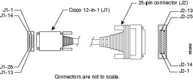
Table A-9 EIA/TIA-232 DTE Cable Pinouts (Cisco 12-in-1 to DB-25) 1
J1-23
J1-24MODE_0
MODE_DCELocal connections
-
-
-
-
-
Shield
-
J2-1
Shield GND
J1-1
J1-14O_TxD/RxD+
GNDTwisted pair no. 5
——>
—J2-2
TxD
GNDJ1-5
J1-18I_RxD/TxD
GNDTwisted pair no. 9
<——
—J2-3
RxD
GNDJ1-8
J1-7O_CTS/RTS+
O_DTR/DSR+Twisted pair no. 4
——>
——>J2-4
J2-20RTS
DTRJ1-11
J1-121_RTS/CTS+
1_DTR/DSR+Twisted pair no. 2
<——
<——J2-5
J2-6CTS
DSRJ1-6
J1-19B_DCD/DCD+
GNDTwisted pair no. 1
<——
—J2-8
J2-7DCD
GNDJ1-3
J1-16B_TXC/TXC+
Circuit GNDTwisted pair no. 7
<——
—J2-15
TXC
GNDJ1-4
J1-17I_RXC/TXCE+
GNDTwisted pair no. 8
<——
—J2-17
RXC
GNDJ1-13
J1-26B_LL/LL+
GNDTwisted pair no. 3
——>
—J2-18
LTST
GNDJ1-2
J1-15O_TxCE/RXC+
GNDTwisted pair no. 6
——.
—J2-24
TxCE
GND
1 Any pin not referenced is not connected.
Table A-10 EIA/TIA-232 DCE Cable Pinouts (Cisco 12-in-1 to DB-25) 1
J1-23
MODE_0
Local connections
-
-
-
-
-
Shield
-
J2-1
Shield GND
J1-5
J1-18I_RxD/TxD
GNDTwisted pair no. 5
<——
—J2-2
RxD
GNDJ1-1
J1-14O_TxD/RxD+
GNDTwisted pair no. 9
——>
—J2-3
TxD
GNDJ1-11
J1-121_RTS/CTS+
1_DTR/DSR+Twisted pair no. 2
<——
<——J2-4
J2-20CTS
DSRJ1-8
J1-7O_CTS/RTS+
O_DTR/DSR+Twisted pair no. 4
——>
——>J2-5
J2-6RTS
DTRJ1-6
J1-19B_DCD/DCD+
GNDTwisted pair no. 1
——>
—J2-8
J2-7DCD
GNDJ1-3
J1-16B_TXC/TXC+
Circuit GNDTwisted pair no. 7
——>
—J2-15
TXC
GNDJ1-2
J1-15O_TxCE/RXC+
GNDTwisted pair no. 8
——>
—J2-17
TxCE
GNDJ1-13
J1-26B_LL/LL+
GNDTwisted pair no. 3
<——
—J2-18
LTST
GNDJ1-4
J1-17I_RXC/TXCE+
GNDTwisted pair no. 6
<——
—J2-24
RXC
GND
1 Any pin not referenced is not connected.
EIA/TIA-449
Figure A-8 shows the EIA/TIA-449 cable assembly; Table A-11 lists the DTE pinouts; Table A-12 lists the DCE pinouts. Arrows indicate signal direction.
Figure A-8 EIA/TIA-449 Cable Assembly
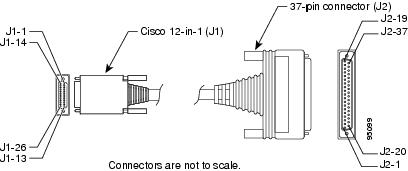
Table A-11 EIA/TIA-449 DTE Cable Pinouts (Cisco 12-in-1 to DB-37) 1
-
-
Shield
—
J2-1
Shield GND
J1-22
J1-24MODE_1
MODE_DCETwisted pair no. 2
—
—>J2-19
J2-20SG
RCJ1-1
J1-14O_TxD/RxD+
O_TxD/RxD-Twisted pair no. 5
——>
——>J2-4
J2-22SD+
SD-J1-3
J1-16B_TxC/TxC+
B_TxC/TxC-Twisted pair no. 7
<——
<——J2-5
J2-23ST+
ST-J1-5
J1-18I_RxD/TxD+
I_RxD/TxD-Twisted pair no. 9
<——
<——J2-6
J2-24RD+
RD-J1-8
J1-9O_RTS/CTS+
O_RTS/CTS-Twisted pair no. 1
——>
——>J2-7
J2-25RS+
RS-J1-4
J1-17I_RxC/TxCE+
I_RxC/TxCE-Twisted pair no. 8
<——
<——J2-8
J2-26RT+
RT-J1-11
J1-10I_CTS/RTS+
I_CTS/RTS-Twisted pair no. 4
<——
<——J2-9
J2-27CS+
CS-J1-13
J1-26B_LL/LL
GNDTwisted pair no. 12
——>
—J2-10
J2-37LL
SCJ1-12
J1-25I_DSR/DTR+
I_DSR/DTR-Twisted pair no. 10
<——
<——J2-11
J2-29DM+
DM-J1-7
J1-20O_DTR/DSR+
O_DTR/DSR-Twisted pair no. 3
——>
——>J2-12
J2-30TR+
TR-J1-6
J1-19B_DCD/DCD+
B_DCD/DCD-Twisted pair no. 6
<——
<——J2-13
J2-31RR+
RR-J1-2
J1-15O_TxCE/TxC+
O_TxCE/TxC-Twisted pair no. 6
——>
——>J2-17
J2-35TT+
TT-
1 Any pin not referenced is not connected.
Table A-12 EIA/TIA-449 DCE Cable Pinouts (Cisco 12-in-1 to DB-37) 1
-
-
Shield
—
J2-1
Shield GND
J1-22
MODE_1
Twisted pair no. 2
-
J2-19
J2-20SG
RCJ1-5
J1-18I_RxD/TxD+
I_RxD/TxD-Twisted pair no. 5
<——
<——J2-4
J2-22SD+
SD-J1-3
J1-16O_TxCE/TxC+
O_TxCE/TxC-Twisted pair no. 9
——>
——>J2-5
J2-23ST+
ST-J1-1
J1-14O_TxD/RxD+
O_TxD/RxD-Twisted pair no. 9
——>
——>J2-6
J2-24RD+
RD-J1-11
J1-10I_CTS/RTS+
I_CTS/RTS-Twisted pair no. 1
<——
<——J2-7
J2-25RS+
RS-J1-2
J1-15O_TxC/RxC+
O_TxC/RxC-Twisted pair no. 8
——>
——>J2-8
J2-26RT+
RT-J1-8
J1-9O_RTS/CTS+
O_RTS/CTS-Twisted pair no. 4
——>
——>J2-9
J2-27CS+
CS-J1-13
J1-26B_LL/LL+
Circuit GNDTwisted pair no. 12
——>
—J2-10
J2-37LL
SCJ1-7
J1-20O_DTR/DSR+
O_DTR/DSR-Twisted pair no. 10
——>
——>J2-11
J2-29DM+
DM-J1-12
J1-25I_DSR/DTR+
I_DSR/DTR-Twisted pair no. 3
<——
<——J2-12
J2-30TR+
TR-J1-6
J1-19B_DCD/DCD+
B_DCD/DCD-Twisted pair no. 11
——>
——>J2-13
J2-31RR+
RR-J1-4
J1-17I_RxC/TxCE+
I_RxC/TxCE-Twisted pair no. 6
<——
<——J2-17
J2-35TT+
TT-
1 Any pin not referenced is not connected.
V.35
Figure A-9 shows the V.35 cable assembly; Table A-13 lists the DTE pinouts; Table A-14 lists the DCE pinouts.
Figure A-9 V.35 Cable Assembly
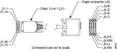
Table A-13 V.35 DTE Cable Pinouts (Cisco 12-in-1 to 34-Pin) 1
J1-22
J1-23
J1-24MODE_1
MODE_0
MODE_DCELocal connections
-
-
-
-
-
Shield
—
J2-A
Shield GND
J1-8
J1-7O_RTS/CTS+
O_DTR/DSR+Twisted pair no. 4
——>
——>J2-C
J2-HRTS
DTRJ1-11
J1-12I_CTS/RTS+
I_DSR/DTR+Twisted pair no. 2
<——
<——J2-D
J2-ECTS
DSRJ1-6
J1-19B_DSR/DTR+
GNDTwisted pair no. 1
<——
—J2-F
RLSD
GNDJ1-13
J1-26B_LL/LL+
GNDTwisted pair no. 3
——>
—J2-K
J2-BLT
GNDJ1-1
J1-14O_TxC/RxD+
O_TxD/RxD-Twisted pair no. 5
——>
——>J2-P
J2-SSD+
SD-J1-5
J1-18I_RxD/TxD+
I_RxD/TxD-Twisted pair no. 9
<——
<——J2-R
J2-TRD+
RD-J1-2
J1-15O_TxCE/RxC+
O_TxCE/RxC-Twisted pair no. 6
——>
——>J2-U
J2-WSCTE+
SCTE-J1-4
J1-17I_RxC/TxCE+
I_RxC/TxCE-Twisted pair no. 8
<——
<——J2-V
J2-XSCR+
SCR-J1-3
J1-16B_TxC/TxC+
B_TxC/TxC-Twisted pair no.7
<——
<——J2-Y
J2-AASCT+
SCT-
1 Any pin not referenced is not connected.
Table A-14 V.35 DCE Cable Pinouts (Cisco 12-in-1 to 34-Pin) 1
J1-22
J1-23MODE_1
MODE_0Local connections
-
-
-
-
-
Shield
—
J2-A
Shield GND
J1-11
J1-12I_CTS/RTS+
I_DSR/DTR+Twisted pair no. 4
<——
<——J2-C
J2-HRTS
DTRJ1-8
J1-7O_RTS/CTS+
O_DTR/DSR+Twisted pair no. 2
——>
——>J2-D
J2-ECTS
DSRJ1-6
J1-19B_DCD/DCD+
GNDTwisted pair no. 1
——>
—J2-F
RLSD
GNDJ1-13
J1-26B_LL/LL+
GNDTwisted pair no. 3
<——
—J2-K
J2-BLT
GNDJ1-5
J1-18I_RxD/TxD+
I_RxD/TxD-Twisted pair no. 5
<——
<——J2-P
J2-SSD+
SD-J1-1
J1-14O_TxC/RxD+
O_TxD/RxD-Twisted pair no. 9
——>
——>J2-R
J2-TRD+
RD-J1-4
J1-17I_RxC/TxCE+
I_RxC/TxCE-Twisted pair no. 6
<——
<——J2-U
J2-WSCTE+
SCTE-J1-2
J1-15O_TxCE/RxC+
O_TxCE/RxC-Twisted pair no. 8
——>
——>J2-V
J2-XSCR+
SCR-J1-3
J1-16B_TxC/TxC+
B_TxC/TxC-Twisted pair no.7
——>
——>J2-Y
J2-AASCT+
SCT-
1 Any pin not referenced is not connected.
X.21
Figure A-10 shows the X.21 cable assembly; Table A-15 lists the DTE pinouts; Table A-16 lists the DCE pinouts. Arrows indicate signal direction.
Figure A-10 X.21 Cable Assembly
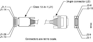
Table A-15 X.21 DTE Cable Pinouts (Cisco 12-in-1 to DB-15) 1
J1-21
J1-24MODE_1
MODE_0Local connections
-
-
-
-
-
Shield
—
J2-1
Shield GND
J1-1
J1-14O_TxD/RxD+
O_TxD/RxD-Twisted pair no. 5
——>
——>J2-2
J2-9Transmit+
Transmit-J1-8
J1-9O_RTS/CTS+
O_RTS/CTS-Twisted pair no. 3
——>
——>J2-3
J2-10Control+
Control-J1-5
J1-18I_RxD/TxD+
I_RxD/TxD-Twisted pair no. 8
<——
<——J2-4
J2-11Receive+
Receive-J1-11
J1-10I_CTS/RTS+
I_CTS/RTS-Twisted pair no. 2
<——
<——J2-5
J2-12Indication+
Indication-J1-4
J1-17I_RxC/TxCE+
I_RxC/TxCE-Twisted pair no. 7
<——
<——J2-6
J2-13Timing+
Timing-J1-26
Circuit GND
Twisted pair2 no. 1
—
J2-8
Circuit GND
1 Any pin not referenced is not connected.
2 Twisted pairs 4, 6, and 9 are not used.
Table A-16 X.21 DCE Cable Pinouts (Cisco 12-in-1 to DB-15) 1
J1-21
MODE_2
Local connections
-
-
-
-
-
Shield
—
J2-1
Shield GND
J1-5
J1-8I_RxT/TxD+
I_RxD/TxD-Twisted pair no. 5
<——
<——J2-2
J2-9Transmit+
Transmit-J1-11
J1-10I_RTS/CTS+
I_RTS/CTS-Twisted pair no. 3
<——
<——J2-3
J2-10Control+
Control-J1-1
J1-14O_TxD/RxD+
O_TxD/RxD-Twisted pair no. 8
——>
——>J2-4
J2-11Receive+
Receive-J1-8
J1-9O_CTS/RTS+
O_CTS/RTS-Twisted pair no. 2
——>
——>J2-5
J2-12Indication+
Indication-J1-2
J1-15O_RxC/TxCE+
O_RxC/TxCE-Twisted pair no. 7
——>
——>J2-6
J2-13Timing+
Timing-J1-26
Circuit GND
Twisted pair2 no. 1
—
J2-8
Circuit GND
1 Any pin not referenced is not connected.
2 Twisted pairs 4, 6, and 9 are not used.
Fast Ethernet Port Pinouts (RJ-45)
Figure A-11 shows the RJ-45 connector wiring for the Fast Ethernet cable; Figure A-11 lists the pinouts.
Note
Figure A-11 RJ-45 Connector Wiring
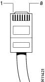
Table A-17 Fast Ethernet Port Pinouts (RJ-45)
1
TX+
2
TX-
3
RX+
4
-
5
-
6
RX-
7
-
8
-
1 Any pin not referenced is not connected.
T1/E1-WAN and T1/E1-PBX Port Pinouts (RJ-48C/CA81A)
Figure A-12 shows the RJ-48 connector wiring for the T1/E1 trunk cable and the digital voice port cable; Table A-18 lists the pinouts.
Figure A-12 RJ-48 Connector Wiring
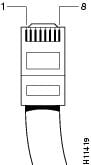
Table A-18 Pinouts for T1/E1-WAN and T1/E1-PBX Ports (RJ-48C/CA81A)
1
RX (input)
2
RX (input)
3
-
4
TX (output)
5
TX (output)
6
-
7
-
8
-
1 Any pin not referenced is not connected.
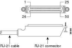
Analog Voice Multiport Pinouts (RJ-21X/CA21A)
Figure A-13 shows the RJ-21 connector wiring for the cable used for the multiport analog voice interface; Table A-19 lists the pinouts.
Figure A-13 RJ-21 Connector Wiring
Synchronous Serial Interface Cable Information
DTE or DCE
A device that communicates over a synchronous serial interface is either a DTE or DCE device. A DCE device provides a clock signal; a DTE device does not provide a clock signal. DTE devices usually connect to DCE devices. The documentation that shipped with the device should indicate whether it is a DTE or DCE device. (Some devices have a jumper to select either mode.) If you cannot find the information in the documentation, refer to Table A-20 to help you select the proper device type. The synchronous serial ports on a Cisco IAD can be configured as DTE or DCE (opposite to the device being connected).
Table A-20 Typical DTE and DCE Devices
DTE
Male1
•
•
•
DCE
Female2
•
•
•
1 If pins protrude from the face of the connector, the connector is male.
2 If the connector face has holes to accept pins, the connector is female.
3 CSU/DSU-channel service unit/data service unit.
Signaling Standards
The synchronous serial port supports the following signaling standards: EIA/TIA-232, EIA/TIA-449, V.35, X.21, EIA/TIA-530, and EIA/TIA-530A. You can order a shielded serial transition cable for your application. One end of this cable has a Cisco 12-in-1 connector, which connects to one of the serial ports on the WIC in your Cisco IAD. The other end has the connector required for the signaling standard being used. The documentation for the device you want to connect to should indicate the standard used for that device.
Note
Figure A-14 shows the serial transition cables you can connect to the serial port on the WIC used in your Cisco IAD.
Figure A-14 Serial Transition Cables

Although attempting to manufacture your own serial cables is not recommended, cable pinouts are provided in the "Serial Cable Assemblies and Pinouts" section. To order a cable, see the "Obtaining Technical Assistance" section on page xviii.

Timesaver
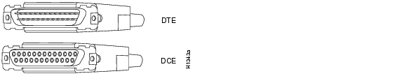
EIA/TIA-232 Connections
The EIA/TIA-232 standard supports unbalanced circuits at signal speeds up to 64 kbps.
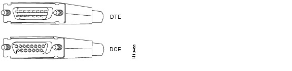
For connection to a Cisco IAD serial port, use the EIA/TIA-232 serial transition cable with the Cisco 12-in-1 connector on one end and a DB-25 connector (as shown in Figure A-15) on the other. The DB-25 connector can be male for DTE or female for DCE. To order a cable, see the "Obtaining Technical Assistance" section on page xviii.
Figure A-15 EIA/TIA-232 Serial Transition Cable Connectors
EIA/TIA-449 Connections
The EIA/TIA-449 standard, which supports balanced and unbalanced transmissions, is a faster (up to 2 Mbps) version of the EIA/TIA-232 standard that provides more functions and supports transmission over greater distances.
The EIA/TIA-449 standard was intended to replace the EIA/TIA-232 standard. However, this standard was not widely adopted because of the large installed base of DB-25 hardware. Also, the larger size of the 37-pin EIA/TIA-449 connectors limited the number of connections possible (fewer than are possible with the smaller, 25-pin EIA/TIA-232 connector).
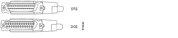
To make a connection to a Cisco IAD serial port, use the EIA/TIA-449 serial transition cable with the Cisco 12-in-1 connector on one end and a DB-37 connector (as shown in Figure A-16) on the other. The DB-37 connector can be male for DTE or female for DCE. To order a cable, see the "Obtaining Technical Assistance" section on page xviii.
Figure A-16 EIA/TIA-449 Serial Transition Cable Connectors
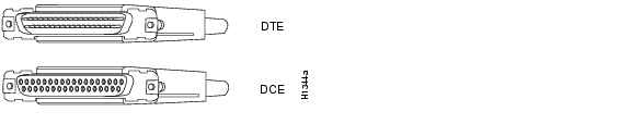
V.35 Connections
The V.35 standard is recommended for speeds up to 48 kbps, although in practice it is used successfully at 4 Mbps. The Cisco IAD supports speeds up to 2.048 Mbps.
Use the V.35 serial transition cable (not included) with the Cisco 12-in-1 connector on one end and a standard 34-pin Winchester-type connector (as shown in Figure A-17) on the other. The 34-pin Winchester-type connector can be male for DTE or female for DCE. To order a cable, see the "Obtaining Technical Assistance" section on page xviii.
Figure A-17 V.35 Serial Transition Cable Connectors
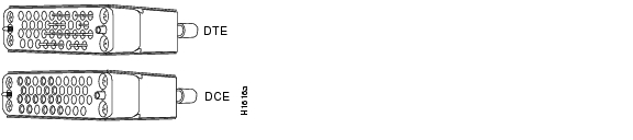
X.21 Connections
The X.21 connector uses a 15-pin connector for balanced circuits and is commonly used in the United Kingdom to connect to the public data network. X.21 relocates some of the logic functions to the DTE and DCE interfaces and, as a result, requires fewer circuits and a smaller connector than EIA/TIA-232.
Use the X.21 serial transition cable (not included) with the Cisco 12-in-1 connector on one end and a DB-15 connector (as shown in Figure A-18) on the other. The DB-15 connector can be male for DTE or female for DCE. To order a cable, see the "Obtaining Technical Assistance" section on page xviii.
Figure A-18 X.21 Serial Transition Cable Connectors
EIA/TIA-530 Connections
The EIA/TIA-530 standard, which supports balanced transmission, provides the increased functionality, speed, and distance of EIA/TIA-449 on the smaller, DB-25 connector used for EIA/TIA-232. Like EIA/TIA-449, EIA/TIA-530 refers to the electrical specifications of EIA/TIA-422 and EIA/TIA-423. Although the specification recommends a maximum speed of 2 Mbps, EIA/TIA-530 is used successfully at 4 Mbps or faster speeds over short distances. Cisco IADs support speeds up to 2.048 Mbps.
Use the EIA/TIA-530 serial transition cable (not included) with the Cisco 12-in-1 connector on one end and a DB-25 connector (as shown in Figure A-19) on the other. The DB-25 connector can be male for DTE or female for DCE. To order a cable, see the "Obtaining Technical Assistance" section on page xviii.
Figure A-19 EIA/TIA-530 Serial Transition Cable Connectors
 Feedback
Contact Cisco
- Open a Support Case

- (Requires a Cisco Service Contract)
This Document Applies to These Products
- Collaboration Endpoints - Retired Products
- Conferencing - Retired Products
- Contact Center - Retired Products
- Optical Networking - Retired Products
- Routers - Retired Products
- Security - Retired Products
- Servers - Unified Computing (UCS) Retired Products
- Storage Networking Retired Products
- Switches - Retired Products
- Video - Retired Products
- Wireless - Retired Products