Cisco H.323 Version 2 Phase 2
Available Languages
Table Of Contents
Gateway Support for Alternate Endpoints
Gateway Support for a Network-Based Billing Number
Gateway Support for Voice-Port Description
Related Features and Technologies
Supported Standards, MIBs, and RFCs
Configuring H.323 Fast Connect
Configuring Call Transfer Without Consultation
Configuring Voice-Port Descriptions
Configuring a RADIUS/AAA Server
Configuring a Dialing Prefix for each Gateway
Configuring a Gatekeeper for Interaction with External Applications
Configuring Triggers for External Applications
Cisco H.323 Version 2 Phase 2
Feature History
12.1(1)T
This feature was introduced.
12.1(5)XM2
Support was added for the Cisco AS5350 and Cisco AS5400 universal gateways.
This feature module describes enhancements to Cisco H.323 Version 2 for Phase 2, which is described in the following sections:
•
Supported Standards, MIBs, and RFCs
Feature Overview
Cisco H.323 Version 2 Phase 2 upgrades Cisco IOS software by adding several optional features of the H.323 Version 2 specification and facilitates customized extensions to the Cisco Gatekeeper.
H.323v2 Fast Connect
The Fast Connect feature allows endpoints to establish media channels without waiting for a separate H.245 connection to be opened. This streamlines the number of messages that are exchanged and the amount of processing that must be done before endpoint connections can be established. A high-level view of the Fast Connect procedures within the H.323 protocol follows:
1.
2.
3.
This feature is not explicitly configurable. It is assumed that the gateway is capable of sending and receiving Fast Connect procedures unless its corresponding dial peer has been configured for RSVP (in other words, the req-qos is set to a value other than the default of best-effort). If the dial peer has been configured for RSVP, then traditional "slow" connect procedures will be followed, and the endpoint will neither attempt to initiate Fast Connect nor respond to a Fast Connect request from its peer.
A terminating endpoint can reject Fast Connect by simply omitting the fastStart element from all Q.931 messages up to and including CONNECT. In this case, normal H.245 procedures are followed and a separate H.245 TCP connection is established. So, if an endpoint does not support the Fast Connect procedures, normal H.245 procedures are followed. In addition, certain conditions can cause a Fast Connect call to fall back to normal H.245 procedures to complete the call.
Once a media connection has been opened (an audio path has been established), either endpoint has the option of switching to H.245 procedures (if they are needed) by using H.245 tunneling, whereby H.245 messages are encapsulated within the h245Control element of Q.931 messages.
The dtmf-relay command is the only H.245 cognizant command that can initiate H.245 tunneling procedures from a Fast Connect call. If H.245 tunneling is active on the call, switching to a separate TCP H.245 connection is not supported.
A Cisco terminating endpoint accepts a Fast Connect request only if a pair of symmetric codecs (codecs in both directions are the equivalent or identical) can be selected from a list that has been offered. The originating endpoint is constrained only by what it can send through the codec (or voice class codec list) associated with the dial peer.
If the Cisco originating endpoint has offered multiple codecs and the terminating endpoint selects a pair of asymmetric (mismatched) codecs, then, the originating endpoint initiates separate H.245 procedures to correct the asymmetric codec situation.
Fast Connect is backward compatible with H.323 Version 1 configurations.
H.245 Tunneling
Through H.245 tunneling, H.245 messages are encapsulated within Q.931 messages without using a separate H.245 TCP connection. When tunneling is enabled, one or more H.245 messages can be encapsulated in any Q.931 message. H.245 tunneling is not supported as a standalone feature; initiation of H.245 tunneling procedures can be initiated only by using the dtmf-relay command, and only from an active Fast Connect call. Furthermore, if dtmf-relay is configured on a Version 2 VoIP dial peer and the active call has been established by using Fast Connect, tunneling procedures initiated by the opposite endpoint are accepted and supported.
H.245 tunneling is backward compatible with H.323 Version 1 configurations.
H.450.2 Call Transfer
Call Transfer allows an H.323 endpoint to redirect an answered call to another H.323 endpoint. Cisco gateways support H.450.2 Call Transfer as the transferred and transferred-to party. The transferring endpoint must be an H.450-capable terminal; the Cisco gateway cannot act as the transferring endpoint. Gatekeeper-controlled or Gatekeeper-initiated Call Transfer is not supported.

Note
H.450.2 specifies two variants of Call Transfer:
1.
2.
H.450.3 Call Deflection
Call Deflection is a feature under H.450.3 Call Diversion (Call Forwarding) that allows a called H.323 endpoint to redirect the unanswered call to another H.323 endpoint. Cisco gateways support H.450.3 Call Deflection as the originating, deflecting, and deflected-to gateway. The Cisco gateway as the deflecting gateway will support invocation of Call Deflection only by using an incoming PRI QSIG message (a Call Deflection cannot be invoked by using any other trunk type).
If the deflecting endpoint is a Cisco gateway, the telephony endpoint on the deflecting gateway's PRI invokes Call Deflection by sending an equivalent QSIG Reroute Invoke within a FACILITY message to the gateway. The deflecting gateway then uses the procedures outlined in H.450.3 Call Deflection to transfer the call to another endpoint. Note that the initiation of Deflection using QSIG Reroute Invoke is valid only on calls that arrived as H.323 calls at the deflecting Gateway. In other words, for calls that arrived at the Gateway through a telephony interface (such as a hairpin call) or using a non-H.323 IP protocol, QSIG Reroute Invoke will be ignored.
H.323 Version 2 Phase 2 does not support Gatekeeper-controlled or initiated Call Deflection.
Note
Hookflash Relay
A "hookflash" indication is a brief on-hook condition during a call. The indication is not long enough in duration to be interpreted as a signal to disconnect the call. You can create a hookflash indication by quickly depressing and releasing the hook on your telephone.
PBXs and telephone switches are frequently programmed to intercept hookflash indications and use them as a way to allow a user to invoke supplemental services. For example, your local service provider might allow you to enter a hookflash as a means of switching between calls if you subscribe to a call-waiting service.
In the traditional telephone network, a hookflash results in a voltage change on the telephone line. Because there is no equivalent of this voltage change in an IP network, the ITU H.245 standard defines a message representing a hookflash. To send a hookflash indication using this message, an H.323 endpoint sends an H.245 user input indication message containing a "H.245-signal" or "H.245-alpha" structure with a value of "!". This value represents a hookflash indication.
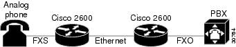
Figure 1 Translating an FXS hookflash to an H.245 User Input
In H.323 Version 2 Phase 2, an FXS hookflash relay is generated only if the following two conditions are met:
1.
2.
This implies that the VoIP dial peer must be configured for dtmf-relay h245-alpha or h245-signal, but not cisco-rtp.
Enter the timing hookflash-input command on FXS interfaces to specify the maximum length in milliseconds of a hookflash indication. If the hookflash lasts longer than the specified limit, then the FXS interface processes the indication as an onhook.
The acceptable duration of a hookflash indication varies by equipment vendor and by country. One PBX can consider a 250 ms on-hook condition to be a hookflash; another PBX can consider this condition to be a disconnect.
H.235 Security
Security for Registration, Admission, and Status protocol (RAS) signaling between H.323 endpoints and Gatekeepers is enhanced in H.323 Version 2 Phase 2 by including secure endpoint registration of the Cisco gateway to the Cisco Gatekeeper and secure per-call authentication. The authentication type is "password with hashing" as described in ITU H.235. Specifically, the encryption method is MD5 with password hashing. This functionality is provided by the security token required-for CLI on the Gatekeeper and the security password CLI on the gateway.
The Gatekeeper can interact with a RADIUS security server to perform the authentications. The gateway can also authenticate an external application by using the Gatekeeper Transaction Message Protocol (GKTMP) API.
Per-call authentication is accomplished by validating account and pin numbers that are entered by the user connected to the calling gateway by using an interactive voice response (IVR) prompt.
The security mechanisms described above require the gateway and Gatekeeper clocks to be synchronized within 30 seconds of each other by using a Network Time Protocol (NTP) server.
GKTMP
The Gatekeeper Transaction Message Protocol (GKTMP) for the Cisco Gatekeeper provides a transaction-oriented application protocol that allows an external application to modify Gatekeeper behavior by processing specified RAS messages.
You can specify a set of triggers that use RAS messages that the Gatekeeper recognizes. Triggers are specified filter conditions that must match each type of RAS message. These triggers can be dynamically registered by using the external application, or you can configure this information by using the CLI on the Gatekeeper.
When the Gatekeeper receives a RAS message that meets the specified trigger conditions, it forwards the message to the external application in a GKTMP message format. This message is text encoded and sent over TCP. The external application can then modify fields in the message before returning it to the Gatekeeper for further processing, or it may return a RAS response to the Gatekeeper to be forwarded to the RAS client.
The following messages can be sent in GKTMP:
•
•
•
•
•
•
•
•
•
•
The application server interprets RAS messages in the following ways:
•
•
•
Note
To configure the Gatekeeper to receive trigger registrations from the external applications, specify the server's registration port using the server registration-port command where the Gatekeeper listens for server connections.
You can also configure the Gatekeeper to initiate the connection to a specified external application by using the server trigger command to specify a set of static trigger conditions for a specified server. You can specify only one application server for each server trigger command. All RAS messages that don't match the selection criteria for any external application are processed normally by the Gatekeeper. You can enter the show Gatekeeper servers and debug Gatekeeper servers commands to assist in the configuration.
Gateway Support for Alternate Endpoints
The Alternate Endpoint feature allows a Gatekeeper to specify alternative destinations for a call when queried with an Admission Request (ARQ) by an originating gateway. If the first destination gateway fails to connect, the Gatekeeper tries all the alternate destinations before going to the next dial peer rotary (if a rotary is configured).
Note
Gateway Support for a Network-Based Billing Number
This feature informs the Gatekeeper of the specific voice port or T1/E1 span from which an incoming call entered the ingress gateway. This is done using a Cisco proprietary, nonstandard field that has been added to the Admission Request (ARQ) message sent by the ingress gateway. No configuration is necessary for this feature.
Gateway Support for Voice-Port Description
This feature provides the Gatekeeper with a configurable string that identifies the voice port or T1/E1 span from which an incoming call entered the ingress gateway. This is done using a Cisco proprietary, nonstandard field that has been added to the ARQ message sent by the ingress gateway. The string in the ARQ corresponds to the setting of the voice-port description command.
This feature is similar to network-based billing number feature, but differs in two important respects:
•
•
Benefits
Cisco H.323 Version 2 Phase 2 adds the following benefits to Cisco H.323 Gatekeepers, gateways, and proxies:
•
•
•
•
•
•
•
•
•
•
Restrictions
H.323 Version 2 Phase 2 features will not interoperate with H.323 Version 1 features in Cisco IOS releases earlier than 11.3(9)NA or 12.0(3)T. Earlier Cisco IOS releases contain H.323 Version 1 software that does not support protocol messages with an H.323 Version 2 protocol identifier.
Note
To use H.450 services (Call Transfer or Call Deflection), you must use Release 12.1(1)T of the Gatekeeper; H.450 on the gateways is incompatible with previous releases of the Cisco Gatekeeper.
If you are planning to use a Cisco AS5300 universal access server, your software requires VCWare Version 4.04.
Related Features and Technologies
Cisco H.323 Version 2 technologies are typically configured by using a number of available compression and decompression (CODECs) and the following high-density DSP/voice modules.
Related Documents
•
•
•
•
•
•
The following table lists the documentation available for configuring and using Cisco IOS H.323 Gatekeepers, gateways, and proxies:
.
Supported Platforms
The Gatekeeper and proxy features apply to the following platforms:
•
•
•
•
•
The gateway features apply to the following platforms:
•
•
•
•
•
•
•
•
•
Supported Standards, MIBs, and RFCs
Standards
This feature adds support for the following ITU-T standards: H.323 Annex E and H.323 Annex G.
MIBs
No new or modified MIBs are supported by this feature.
To obtain lists of MIBs supported by platform and Cisco IOS release and to download MIB modules, go to the Cisco MIB web site on Cisco Connection Online(CCO) at
http://www.cisco.com/public/sw-center/netmgmt/cmtk/mibs.shtml.RFCs
No new or modified RFCs are supported by this feature.
This feature provides support for the following ITU-T Recommendations:
•
•
•
•
•
•
•
Prerequisites
The Cisco AS5350 and Cisco AS5400 do not support the Mica Modem Card, Microcom Modem Card, or VoIP Feature Card. Voice and modem functions are provided by the Universal Port Dial Feature card running SPE firmware. See the Cisco AS5350 Universal Gateway Card Installation Guide and the Cisco AS5400 Universal Gateway Card Installation Guide for more information. All references to the Cisco AS5300 in this document apply to the Cisco AS5350 and Cisco AS5400 platforms with the following exceptions:
•
•
•
Other Prerequisites
Before you can use H.323 Version 2 Phase 2 features, you must:
•
•
•
•
•
•
Configuration Tasks
The H.323 Version 2 Phase 2 configuration options allow you to configure the H.323 components discussed in the following sections:
•
•
Note
For the Cisco AS5300 access server, port designation is port.
For the Cisco AS5400 gateway, port designation is slot/port.
For the Cisco AS5800 access server, port designation is shelf/slot/port.
Configuring H.323 Fast Connect
Because Fast Connect is a H.323 Version 2 compliant feature and the majority of endpoints prefer to establish a call by using Fast Connect procedures, this feature is not configurable. H.323 Fast Connect does not require any additional configuration beyond a working voice configuration.
For more information about configuring voice ports, see "Configuring Voice Ports" in the Cisco IOS Release 12.0 Voice, Video, and Home Applications Configuration Guide.
Configuring H.245 Tunneling
The dtmf-relay command configured on the outgoing VoIP dial peer initiates H.245 tunneling procedures from a Fast Connect call. Note that H.245 tunneling will be activated only if dtmf-relay "h245-alpha" or "h245-signal" (but not "cisco-rtp") are configured on the VoIP dial peer.
Configuring H.450
How you configure a Cisco gateway for H.450 depends upon whether you want your gateway to:
•
•
Although there are no new CLI commands for configuring H.450 services, the services are enabled only when a TCL/IVR Session Application is configured. Therefore, to use H.450 services, you must configure a TCL/IVR-based "application" on each applicable incoming dial peer for each Cisco Gateway that will be involved in Call Transfer or Call Deflection. If no special TCL/IVR behavior is required, you can use the standard TCL/IVR application "session." This is not to be confused with application "SESSION," which is not TCL/IVR-based and does not support H.450 services.
In addition, if Call Deflection is to be initiated from a QSIG PRI, you must configure the PRI for "isdn switch-type primary-qsig" and "isdn alert end-to-end." See the examples that follow.
Note
Configuring Call Deflection
An example configuration is shown in Figure 2.
Figure 2 H.450 Configuration to Redirect Unanswered Calls
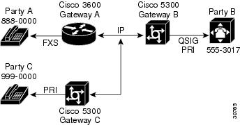
In this example, three gateways are configured to redirect unanswered calls, so that when Party A calls Party B, Party B can invoke deflection to pass the call to Party C. For this to work, you must to configure "application session" or another TCL/IVR-based application on each applicable incoming dial peer as follows:
1.
2.
3.
To configure Gateway A POTS dial peer, follow these steps:
To configure Gateway A global ISDN alert-end-to-end parameter, follow these steps:
To configure Gateway B VoIP peer, follow these steps:
To configure Gateway B PRI, follow these steps:
To configure Gateway C VoIP dial peers, follow these steps:
Configuring Call Transfer Without Consultation
An example configuration is shown in Figure 3.
Figure 3 H.450 Configuration for Calls Transfer Without Consultation
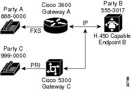
In this example, two gateways are configured to handle call transfers without consultation, so that when Party A calls Party B at 555-3017 at Endpoint B, Endpoint B answers and then invokes Call Transfer to Party C. To do this, you must configure the application session or another TCL/IVR-based application on each applicable incoming dial peer as follows:
1.
2.
To configure Gateway A POTS dial peer, follow these steps:
To configure Gateway C VoIP dial peer, follow these steps:
For more information about POTS dial peers, see Cisco IOS Release 12.0 Voice, Video, and Home Applications Configuration Guide.
For more information about any of the commands used to configure VoIP dial peers, see Cisco IOS Release 12.0 Voice, Video, and Home Applications Command Reference.
Configuring Voice-Port Descriptions
The voice-port description feature uses the existing description subcommand for the voice port. When you configure the voice-port description, the exact contents of the description field are included in the ARQ message sent from the ingress gateway.
Note
To configure the description on a voice-port, follow these steps:
Configuring a RADIUS/AAA Server
To configure the RADIUS/AAA server with information about the Gatekeeper for your network installation, follow these steps:
In addition to the above configuration, make sure that the following information is configured in your CiscoSecure AAA server:
•
#Client Name Key#----------- -------------------gk215.cisco.com testing123Where:
gk215.cisco.com is resolved to the IP address of the Gatekeeper requesting authentication
and
taeduk@cisco.com is the h323-id of the gateway authenticating to Gatekeeper gk215.cisco.com.
•
taeduk@cisco.com Password = "thiswouldbethepassword"User-Service-Type = Framed-User,Login-Service = TelnetConfiguring the Gatekeeper
With this version of the Gatekeeper software, you can configure the Gatekeeper for interaction with external applications. Make sure that you include a priority value for selecting between multiple gateways when you configure the Gatekeeper. To configure the Gatekeeper, perform the tasks discussed in the following sections:
•
•
•
Configuring a Dialing Prefix for each Gateway
To put all your gateways in the same zone use the gw-priority argument and specify which gateways are used for calling different area codes. For example:
router(config-gk)# zone local localgk xyz.comrouter(config-gk)# zone prefix localgk 408.......router(config-gk)# zone prefix localgk 415....... gw-pri 10 gw1 gw2router(config-gk)# zone prefix localgk 650....... gw-pri 0 gw1In the above commands the following is accomplished:
•
•
•
•
•
–
–
Configuring a Gatekeeper for Interaction with External Applications
There are two ways of configuring the Gatekeeper for interaction with an external application. You can configure a port number where the Gatekeeper listens for dynamic registrations from applications. Using this method, the application connects to the Gatekeeper and specifies the trigger conditions in which it is interested.
The second method involves using the CLI to statically configure the information about the application and its trigger conditions, in which case the Gatekeeper initiates a connection to the external application.
This configuration is for a Gatekeeper (sj.xyz.com) that uses port 20000 for a specific connection with an external server (Server-123). Server-123 has a number of triggers that are used to maintain a database of active gateways, which are used for active call resolution. The configuration is as follows:
Server-123 establishes a connection with Gatekeeper sj.xyz.com on port 20000 and sends a REGISTER RRQ message to Gatekeeper sj.xyz.com to express interest in all RRQs from voice gateways that support a technology prefix of 1# or 2#.
The following is an example of a registration message:
REGISTER RRQVersion-id:1From:Server-123To:sj.xyz.comPriority:2Notification-Only:Content-Length:29t=voice-gatewayp=1#p=2#When Gatekeeper sj.xyz.com receives this message, the information supplied in the message is added to the trigger list. Then, when an endpoint registers with this Gatekeeper by using an RRQ that matches the specified trigger condition in the message, the Gatekeeper sends a notification to Server-123.
See the following example of an RRQ notification sent from the Gatekeeper to the server when the above trigger condition matches:
REQUEST RRQVersion-id:1From:sj.xyz.comTo:Server-123Notification-Only:Content-Length:89c=I:171.69.136.205:1720r=I:171.69.136.205:16523a=H:gw3-sjt=voice-gatewayp=1# 2#Configuring Triggers for External Applications
To establish statically configured triggers on a router, follow these general steps:
To remove a trigger, enter the no server trigger command. To temporarily suspend a trigger, enter the trigger configuration mode, as described in step 2, and enter the shutdown subcommand.
Configuration Examples
The configuration examples for H.450 and the GKTMP Gatekeeper are described in the following sections:
Command Reference
This section documents new or modified commands for the Gatekeeper. All other commands used with this feature are documented in the Cisco IOS Release 12.1 command reference publications.
security token required-for
To configure the RAS messages so that the Gatekeeper checks for access tokens, enter the security token required-for command from the config-gk mode. To disable the Gatekeeper from checking for tokens in RAS messages, enter the no form of this command.
security token required-for {registration | all}
no security token required-for {registration | all}
Syntax Description
Defaults
No access token is required for authentication if the Gatekeeper is configured.
Command Modes
Gatekeeper configuration mode
Command History
12.1(1)T
This command was first introduced.
12.1(5)XM1
The command was introduced for the Cisco AS5400.
Usage Guidelines
Use this command to configure the Gatekeeper to search for access tokens in RAS messages. These tokens are verified by an AAA server before the Gatekeeper responds. If you use the "registration" option, the Gatekeeper checks for tokens in all heavyweight RRQ messages. If you use the "all" option, the Gatekeeper also checks all ARQ messages—in addition to the RRQ messages.
By using the no option of the command the Gatekeeper stops checking for authentication tokens in RAS messages.
Note
Examples
See the following example to configure a Gatekeeper to utilize an AAA server, enter the gateways that will be registering on the AAA security server, by entering the following commands:
Router# aaa new-modelRouter(config)# aaa authentication login h323 group radiusRouter(config)# radius-server deadtime 120Router(config)# radius-server host 172.18.192.59 auth-port 1645 acct-port 1646 key labRelated Commands
server registration-port
To configure the listener port for the server to establish a connection with the Gatekeeper, enter the server registration-port command from Gatekeeper mode. Enter the no form of this command to force the Gatekeeper to close the listening socket so that no more new registration takes place. However, existing connections between the Gatekeeper and the external applications are left open.
server registration-port port number
no server registration-port port number
Syntax Description
port number
Specifies a single range of values from 1 through 65535 for the port number on which the Gatekeeper listens for external server connections
Defaults
The registration port of the Gatekeeper is not configured, so no external server can register with this Gatekeeper.
Command Modes
Gatekeeper configuration mode
Command History
12.1(1)T
This command was first introduced.
12.1(5)XM1
The command was introduced for the Cisco AS5400.
Usage Guidelines
Use this command to configure a server registration port to poll for servers that want to establish connections with the Gatekeeper on this router.
Note
Examples
See the following example of how a listener port for a server is established for connection with a Gatekeeper:
Router# server registration-port 20000Related Commands
server trigger
Configure static server triggers for specific RAS messages to be forwarded to a specified server.
server trigger
To configure a static server trigger for external applications, enter the server trigger command from Gatekeeper mode. Enter the no form of this command to remove a single statically configured trigger entry. Enter the "all" form of the command to remove every static trigger you configured if you want to delete them all.
server trigger {arq | lcf | lrj | lrq | rrq | urq} gkid priority server-id server-ipaddress server-port
no server trigger {arq | lcf | lrj | lrq | rrq | urq} gkid priority
no server trigger all
Syntax Description
Defaults
No server triggers are set.
Command Modes
Configure from Gatekeeper mode.
Command History
12.1(1)T
This command was first introduced.
12.1(5)XM1
The command was introduced for the Cisco AS5400.
Usage Guidelines
Use this command to configure a static server trigger. There are six different server triggers—one for each of the RAS messages. To configure a trigger, go to its submode where a set of subcommands are used to trigger a condition. See the following examples.
In ARQ submode, enter the following syntax:
router(config-gk)#server trigger arq gkid priorityserver-id server-ipaddressserver-portrouter(config-gk-arqtrigg)#In LCF submode, enter the following syntax:
router(config-gk)#server trigger lcf gkid priorityserver-id server-ipaddressserver-portrouter(config-gk-lcftrigg)#In LRJ submode, enter the following syntax:
router(config-gk)#server trigger lrj gkid priorityserver-id server-ipaddressserver-portrouter(config-gk-lrjtrigg)#In LRQ submode, enter the following syntax:
router(config-gk)#server trigger lrq <gkid> <priority><server-id> <server-ipaddress><server-port>router(config-gk-lrqtrigg)#In RRQ submode, enter the following syntax:
router(config-gk)#server trigger rrq gkid priorityserver-id server-ipaddressserver-portrouter(config-gk-rrqtrigg)#In URQ submode, enter the following syntax:
router(config-gk)#server trigger urq gkid priorityserver-id server-ipaddressserver-portrouter(config-gk-urqtrigg)#The following options are available in all submodes:
The destination-info command is under the ARQ, LRQ, LCF, and LRJ submode and has the following options:
The redirect-reason command is under the ARQ and LRQ submodes and has the following options:
The remote-ext-address command is under the LCF trigger submode and has the following options:
The endpoint-type command is under the RRQ and URQ trigger submodes and has the following options:
The supported-prefix command is under the RRQ and URQ submodes and has the following options:
supported-prefix
Configure the gateway technology prefix to trigger on.
word
Enter a word within the set of "0123456789#*" when configuring the E.164 pattern for a gateway technology prefix.
Entering the no form of the server trigger command removes the trigger definition from the Cisco IOS Gatekeeper with all statically configured conditions under that trigger.
Examples
See the following example to configure a server trigger on Gatekeeper sj.xyz.com to notify external server "Server-123" of any call to an E.164 number that starts with 1800 followed by any 7 digits (1800551212, for example):
Router# GatekeeperRouter(config-gk)# server trigger arq sj.xyz.com 1 Server-123 1.14.93.130 1751Router(config-gk-arqtrigg)#destination-info e164 1800.......Router(config-gk-arqtrigg)#exitRelated Commands
show Gatekeeper servers
Enter the show Gatekeeper servers command to see a list of currently registered and statically configured triggers on this Gatekeeper router.
show Gatekeeper servers [ gkid ]
Syntax Description
Command Modes
EXEC
Command History
12.0(6)T
This command was introduced.
12.1(5)XM1
The command was introduced for the Cisco AS5400.
Usage Guidelines
Enter this command to show all server triggers (whether dynamically registered from the external servers or statically configured from the command line interface) on this Gatekeeper. If gkid is specified, only triggers applied to the specified Gatekeeper zone appear. If gkid is not specified, server triggers for all local Gatekeeper zones on this router appear.
Examples
This example shows the operating information of the specified gk102 server:
Router# show Gatekeeper servers gk102GATEKEEPER SERVERS STATUS=========================Gatekeeper Server listening port:20000Gatekeeper-ID:gk102--------------------RRQ Priority:1Server-ID:sj-serverServer IP address:1.14.93.28:42387Server type:dynamically registeredConnection Status:activeTrigger Information:Supported Prefix:10#Supported Prefix:3#RRQ Priority:2Server-ID:sf-serverServer IP address:1.14.93.43:3820Server type:CLI-configuredConnection Status:inactiveTrigger Information:Endpoint-type:MCUEndpoint-type:VOIP-GWSupported Prefix:99#ARQ Priority:1Server-ID:sj-serverServer IP address:1.14.93.28:42387Server type:dynamically registeredConnection Status:activeTrigger Information:Destination Info:M:nilkant@zone14.comDestination Info:E:1800.......Redirect Reason:Call forwarded no replyRedirect Reason:Call deflectionRelated Commands
timing hookflash-input
Enter the timing hookflash-input command from privileged EXEC mode to specify the maximum duration of a hookflash for an FXS interface. Enter the no form of this command to restore the default duration for hookflash timing.
timing hookflash-input milliseconds
no timing hookflash-input
Syntax Description
.
Defaults
Default value is 600 milliseconds.
Command Modes
Privileged EXEC
Command History
12.1(1)T
This command was introduced.
12.1(5)XM1
The command was introduced for the Cisco AS5400.
Usage Guidelines
This command does not affect whether hookflash relay is enabled; hookflash relay is only enabled when dtmf-relay h245-signal is configured on the applicable VoIP dial peers. Hookflash is relayed by using an h245-signal indication and can be sent only when h245-signal is available.
Enter the timing hookflash-input command on FXS interfaces to specify the maximum duration (in milliseconds) of a hookflash indication. If the hookflash lasts longer than the specified limit, then the FXS interface processes the indication as an on-hook. To set hookflash timing parameters for analog voice interfaces, use the voice-port timing subcommand.
Examples
To implement timing for the hookflash with a duration of 200 milliseconds, see the following example:
Router# configure terminalRouter(config)# voice-port 1/0/0Router(config-voiceport)# timing hookflash-input 200Related Commands
voice-port
Switch to the voice-port configuration mode from the global configuration mode.
timing hookflash-output
Enter the timing hookflash-output command to specify the duration of hookflash indications that the gateway generates on an FXO interface. Enter the no form of this command to restore the default duration for hookflash timing.
timing hookflash-output duration
no timing hookflash-output
Syntax Description
Defaults
Default value is 400 milliseconds.
Command Modes
Privileged EXEC
Command History
12.0(6)T
This command was introduced.
12.1(1)T
The default value was changed.
12.1(5)XM1
The command was introduced for the Cisco AS5400.
Usage Guidelines
This command does not affect whether hookflash relay is enabled; hookflash relay is only enabled when dtmf-relay h245-signal is configured on the applicable VoIP dial peers. Hookflash is relayed by using an h245-signal indication and can be sent only when h245-signal is available
Enter the timing hookflash-output command on FXO interfaces to specify the duration (in milliseconds) of a hookflash indication. To set hookflash timing parameters for analog voice interfaces, use the voice-port timing subcommand.
Examples
To implement timing for the hookflash with a duration of 200ms, see the following example after you have configured voice-port 1/0/0:
Router# configure terminalRouter(config)# voice-port 1/0/0Router(config-voiceport)# timing hookflash-output 200Related Commands
voice-port
Switch to the voice-port configuration mode from the global configuration mode.
Debug Commands
This section documents new or modified debug commands. All other commands used with this feature are documented in the Cisco IOS Release 12.1 command reference publications.
debug Gatekeeper server
Enter the debug Gatekeeper server command from EXEC mode to trace all the message exchanges between the Cisco IOS Gatekeeper and the external applications. Show any errors that occur in sending messages to the external applications or in parsing messages from the external applications. Enter the no form of this command to disable debugging output.
debug Gatekeeper server
no debug Gatekeeper server
Syntax Description
There are no arguments or keywords.
Defaults
Disabled.
Command Modes
EXEC
Command History
12.1(1)T
This command was introduced.
12.1(5)XM1
The command was introduced for the Cisco AS5400.
Usage Guidelines
Use this command to see information about a Gatekeeper server.
Examples
This example shows debugging information about a Gatekeeper server
Router# debug Gatekeeper serversRouter# show debugGatekeeper:Gatekeeper Server Messages debugging is onTo turn the Gatekeeper server debugging message off, see the following example:
Router# no debug allor
Router# no debug Gatekeeper serversRelated Commands
show Gatekeeper server
Show information about the Gatekeeper servers configured on your network by ID.
Glossary
AAA—Authentication, authorization, and accounting. AAA is a suite of network security services that provides the primary framework through which access control can be set up on your Cisco router or access server.
CHAP—Challenge Handshake Authentication Protocol.
CODEC—Compression/decompression software.
DNS—Domain name system used in address translation to convert H.323 IDs, URLs, or e-mail IDs to IP addresses. DNS is also used to locate remote Gatekeepers and to translate names of network nodes into IP addresses or host names of administrative domains.
DNIS—Dialed number identification service (the called number). Feature of trunk lines where the called number is identified; this called number information is used to route the call to the appropriate service.
DTMF—Dual tone multi-frequency.
E1—European digital carrier facility used for transmitting data through the telephone hierarchy. The transmission rate for E1 is 2.048 megabits per second (Mbps).
E.164—International Telecommunication Union (ITU-T) recommendation for international telecommunication numbering. This recommendation provides the number structure and functionality for the three categories of numbers used for international public telecommunication; geographic areas, global services, and networks.
E&M—rEceive and transMit, or Ear and Mouth. Type of signaling originally developed for analog two-state voltage telephony using the ear and mouth leads; in digital telephony, uses two bits.
endpoint—An H.323 terminal or gateway. An endpoint can call and be called. It generates or terminates the information stream.
ESF—Extended Superframe. Framing type used on T1 circuits that consists of 24 frames of 192 bits each, with the 193rd bit providing timing and other functions. ESF is an enhanced version of SF format.
FXO—Foreign Exchange Office. A voice interface emulating a PBX trunk line to a switch or telephone equipment to a PBX extension interface.
FXS—Foreign Exchange Station. A voice interface for connecting telephone equipment, which emulates the extension interface of a PBX or the subscriber interface for a switch.
Gatekeeper—An H.323 entity on the LAN that provides address translation and control access to the LAN for H.323 terminals and gateways. The Gatekeeper can provide other services to the H.323 terminals and gateways, such as bandwidth management and locating gateways. A Gatekeeper maintains a registry of devices in the multimedia network. The devices register with the Gatekeeper at startup and request admission to a call from the Gatekeeper.
gateway—An H.323 endpoint on the LAN that provides real-time, two-way communication between H.323 terminals on the LAN, other ITU-T terminals in the WAN, or to another H.323 gateway. A gateway allows H.323 terminals to communicate with non-H.323 terminals by converting protocols. A gateway is the point where a circuit-switched call is encoded and repackaged into IP packets.
GKAPI—Gatekeeper Application Programming Interface.
GKTMP—Gatekeeper Transaction Message Protocol.
H.245—An ITU-T standard that describes H.245 endpoint control.
H.323—An ITU-T standard that describes packet-based video, audio, and data conferencing. H.323 is an umbrella standard that describes the architecture of the conferencing system and refers to a set of other standards (H.245, H.225.0, and Q.931) to describe its actual protocol.
H.450.2—Call transfer supplementary service for H.323.
H.450.3—Call diversion supplementary service for H.323.
hookflash—A brief on-hook condition that occurs during a call. The on-hook condition is not long enough to be interpreted as a signal to disconnect the call. You can create a hookflash indication by quickly depressing and then releasing the hook on your telephone.
ICW—Internet call waiting service.
IVR—Interactive voice response. Term used to describe systems that provide information in the form of recorded messages over telephone lines in response to user input in the form of spoken words or more commonly DTMF signaling.
ITU-T—International Telecommunications Union-Telecommunication Standardization Sector.
OSP—Open Settlement Protocol.
packet—Logical grouping of information that includes a header containing control information and (usually) user data. Packets are most often used to refer to network layer units of data.
POTS—Plain old telephone service. Basic telephone service supplying standard single line telephones, telephone lines, and access to the Public Switched Telephone Network.
PSTN—Public Switched Telephone Network. General term referring to the variety of telephone networks and services in place worldwide.
Q.931—ITU-T specification for signaling to establish, maintain, and clear ISDN network connections.
QSIG—Q (point of the ISDN model) signaling. A common channel signaling protocol based upon ISDN Q.931 standards for digital PBXs.
RRQ—Registration Request RAS message. This message type is sent from an H.323 endpoint to an H.323 gateway.
RTP—Real Time Transport protocol. See RFC 1889.
SF—Super Frame. Common framing type used on T1 circuits. SF consists of 12 frames of 192 bits each with the 193rd bit providing error checking and other functions. SF is superseded by ESF, but is still widely used. Also called D4 framing.
T1—Digital WAN carrier facility. T1 transmits DS 1-formatted data at 1.544 Mbps through the telephone switching network by using alternate mark inversion or B8ZS coding.
T1 trunk—Digital WAN carrier facility. See T1.
VoIP—Voice over IP. The ability to carry normal telephone-style voice over an IP-based Internet with POTS-like functionality, reliability, and voice quality. VoIP is a blanket term that generally refers to Cisco's standards-based (for example, H.323) approach to IP voice traffic.
zone—A collection of all terminals, gateways, and multipoint control units (MCUs) managed by a single Gatekeeper. A zone has only one Gatekeeper, can be independent of LAN topology, and can comprise multiple LAN segments that are connected by using routers or other devices.
For a list of other internetworking terms, see Internetworking Terms and Acronyms that accompanied your access server and is available on the Documentation CD-ROM and Cisco Connection Online (CCO) at the following URL: http://www.cisco.com/univercd/cc/td/doc/cisintwk/ita/index.htm.
 Feedback
Contact Cisco
- Open a Support Case

- (Requires a Cisco Service Contract)
This Document Applies to These Products
- Collaboration Endpoints - Retired Products
- Conferencing - Retired Products
- Contact Center - Retired Products
- Optical Networking - Retired Products
- Routers - Retired Products
- Security - Retired Products
- Servers - Unified Computing (UCS) Retired Products
- Storage Networking Retired Products
- Switches - Retired Products
- Video - Retired Products
- Wireless - Retired Products