Voice over IP Q.SIG Network Transparency
Available Languages
Table Of Contents
Voice over IP Q.SIG Network Transparency
Configuring VoIP Q.SIG Software on the Cisco AS5300
ISDN Switch Type Command Options
Fusion Call Control Signaling (NEC Fusion)
Verifying VoIP Q.SIG Software on the Cisco AS5300
Voice over IP Q.SIG Network Transparency
Feature History
12.0(7)T
This feature was introduced
12.1(5)XM2
Support was added for the Cisco AS5350 and Cisco AS5400 universal gateways.
This feature module describes the Voice over IP Q.SIG network transparency feature for the Cisco AS5300 and Cisco AS5400. It includes information on the benefits of the new feature, supported platforms, and related documents.
This document includes the following sections:
Feature Overview
Integration of Q.SIG with the Cisco AS5300 universal access server enables Cisco voice switching services to connect private branch exchanges (PBXs), key systems (KTs), and central office switches (COs) that communicate by using the Q.SIG protocol.
The Q.SIG protocol is a variant of ISDN D-channel voice signaling. It is based on the ISDN Q.921 and Q.931 standards and is becoming a worldwide standard for PBX interconnection. By using Q.SIG signaling, the Cisco AS5300 can route incoming voice calls from a private integrated services network exchange (PINX) across a wide-area network (WAN) to a peer Cisco AS5300, which can then transport the signaling and voice packets to a second PINX.

Note
In Cisco IOS Release 12.0(7)T, the Cisco AS5300 supports ISDN PRI only when a Q.SIG connection to the PINX is configured on the T1/E1 controller.
Q.SIG on the AS5300 allows the user to place Q.SIG calls into and receive Q.SIG calls from Cisco Voice-over-IP (VoIP) networks. The Cisco packet network appears to PBXs as a large, distributed transit PBX that can establish calls to any destination served by a Cisco voice node. The switched voice connections are established and torn down in response to Q.SIG control messages that come over an ISDN PRI D channel. The Q.SIG message is passed transparently across the IP network and the message appears to the attached PINXs as a transit network. The PINXs are responsible for processing and provisioning the attached services.
Benefits
Q.SIG voice signaling on the Cisco AS5300 provides the following benefits:
•
•
•
•
–
–
–
–
•
•
•
Restrictions
The following restrictions and limitations apply to the Cisco AS5300 Q.SIG implementation:
•
•
•
Related Documents
•
•
•
•
Supported Platforms
•
•
•
Supported MIBs and RFCs
Standards
No new or modified standards are supported by this feature.
MIBs
No new or modified MIBs are supported by this feature.
To obtain lists of MIBs supported by platform and Cisco IOS release and to download MIB modules, go to the Cisco MIB web site on Cisco Connection Online (CCO) at http://www.cisco.com/public/sw-center/netmgmt/cmtk/mibs.shtml.
RFCs
No new or modified RFCs are supported by this feature.
Prerequisites
The Cisco AS5350 and Cisco AS5400 do not support the Mica Modem Card, Microcom Modem Card, or VoIP Feature Card. Voice and modem functions are provided by the Universal Port Dial Feature card running SPE firmware. See the Cisco AS5350 Universal Gateway Card Installation Guide and the Cisco AS5400 Universal Gateway Card Installation Guide for more information. All references to the Cisco AS5300 in this document apply to the Cisco AS5350 and Cisco AS5400 platforms with the following exceptions:
•
•
•
Other Prerequisites
The following configuration tasks should be completed before configuring this feature:
•
•
•
Configuration Tasks
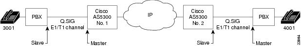
Figure 1 shows an example of a Q.SIG signaling configuration. In this example, the Cisco AS5300 acts as either a master to a slave PBX or as a slave to a master PBX.
Figure 1 Q.SIG Signaling Configuration
Configuring VoIP Q.SIG Software on the Cisco AS5300
To configure Q.SIG signaling support on the Cisco AS5300, complete the following steps, beginning in global configuration mode:
Note
For the Cisco AS5300 access server, port designation is port.
For the Cisco AS5350 and Cisco AS5400 universal gateways, port designation is slot/port.
For the Cisco AS5800 access server, port designation is shelf/slot/port.
Step 1
Router(config)# isdn switch-type primary-qsig
Configures the ISDN switch-type to support Q.SIG signaling.
Note
Note
Step 2
Router(config)# controller {T1 | E1}controller number
Enters interface configuration mode.
Step 3
Router(config-controller)# pri-group
{ timeslots 1-24 }Configures the PRI group for either T1 or E1 to carry voice traffic. For T1, available timeslots are from 1 to 23, and for E1, available timeslots are from 1 to 31.
You can configure the PRI group to include all available timeslots, or you can configure a select group of timeslots for the PRI group. For example, if only timeslots 1 to 10 are in the PRI group, enter pri-group timeslot 1-10. If the PRI group includes all channels available for T1 (channels 1 to 24), enter pri-group timeslot 1-24. If the PRI group includes all channels available for E1 (channels 1 to 31), enter pri-group timeslot 1-31.
Step 4
Router(config-controller)# exit
Exits controller configuration mode.
Step 5
Router(config)# interface serial 1:x
Enters interface configuration mode for the ISDN PRI interface. For T1, enter serial 1:23. For E1, enter serial 1:15.
Step 6
Router(config-if)# isdn switch-type primary-qsig
If you did not configure the global ISDN switch type for Q.SIG support in Step 1, configure the interface ISDN switch type to support Q.SIG signaling.
The conditions that apply to this command in global configuration mode also apply to this command in interface configuration mode.
Note
Step 7
Router(config-if)# isdn protocol-emulate { user | network }
Configures the ISDN interface to serve as either the primary Q.SIG slave or the primary Q.SIG master. For this command, user specifies slave and network specifies master.
If the PINX is the primary Q.SIG master, configure the Cisco AS5300 to serve as the primary Q.SIG slave. If the PINX is the primary Q.SIG slave, configure the Cisco AS5300 to serve as the primary Q.SIG master.
For more information about the different options available with this command, see "ISDN Switch Type Command Options" on page 7.
Step 8
Router(config-if)# isdn overlap-receiving value
Activates overlap signaling to send to the destination PBX.
Note
Step 9
Router(config-if)# isdn incoming-voice modem
Routes incoming voice calls to the modem and treat them as analog data.
Step 10
Router(config-if)# isdn network-failure-cause [value]
(Optional) Specifies the cause code to pass to the PBX when a call cannot be placed or completed because of internal network failures. Possible values are from 1 to 127.
Note
Step 11
Router(config-if)# isdn bchan-number-order {ascending | descending}
(Optional) Configures the ISDN Primary Rate Interface (PRI) interface to make the outgoing call selection in ascending or descending order.
The default is descending order, in which the first call from the Cisco AS5300 uses channel 23 (T1) or channel 31 (E1). The second call then uses channel 22 (T1) or channel 30 (E1), and so on in descending order.
If you select ascending order and the PRI group starts with 1, the first call uses channel 1, the second call uses channel 2, and so on in ascending order. If the PRI group starts with a different timeslot, the ascending order starts with the lowest timeslot.
Step 12
Router(config-if)# exit
Exits interface configuration mode.
ISDN Switch Type Command Options
As shown in the preceding section, you have a choice of configuring the isdn-switch-type command to support Q.SIG at either the global configuration level or the interface configuration level. For example, if you have a Q.SIG connection on one line as well as on the PRI port, you can configure the ISDN switch type in one of the following combinations:
•
•
•
Fusion Call Control Signaling (NEC Fusion)
If you have an NEC PBX in your network and you are running Fusion Call Control Signaling (FCCS), you will need to configure this device appropriately. FCCS, also known as NEC Fusion, allows individual nodes anywhere within a network to operate as if they were part of a single integrated PBX system. The database storage, share, and access routine of NEC Fusion allow real-time access from any node to any other, allowing individual nodes to "learn" about the entire network configuration. This capability allows network-wide feature, functional, operational, and administration transparency.
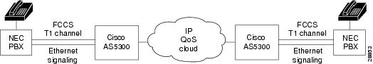
Figure 2 shows an example of a Q.SIG signaling configuration using an NEC PBX.
Figure 2 Q.SIG Signaling Configuration with NEC PBX
To configure NEC Fusion signaling support on the Cisco AS5300, complete the following steps, beginning in global configuration mode:
Verifying VoIP Q.SIG Software on the Cisco AS5300
After you complete the configuration for the AS5300, perform the following steps to verify that you configured Q.SIG properly:
Step 1
Router# show isdn statusGlobal ISDN Switchtype = primary-qsigISDN Serial1:23 interfacedsl 0, interface ISDN Switchtype = primary-qsig**** Slave side configuration ****Layer 1 Status:DEACTIVATEDLayer 2 Status:TEI = 0, Ces = 1, SAPI = 0, State = TEI_ASSIGNEDLayer 3 Status:0 Active Layer 3 Call(s)Activated dsl 0 CCBs = 0The Free Channel Mask: 0x7FFFFF
Configuration Example
The following configuration example configures interface serial 1:23 for Q.SIG PRI and to act as the Q.SIG slave. The example includes the other commands necessary for configuration (see Figure 1).
!version 12.0service timestamps debug uptimeservice timestamps log uptimeno service password-encryption!hostname as5300A!ip subnet-zero!isdn switch-type primary-qsig!controller T1 0shutdown!controller T1 1framing esfclock source line primarylinecode b8zspri-group timeslots 1-24!controller T1 2shutdown!controller T1 3shutdown!!voice-port 1:D!!dial-peer voice 3001 potsdestination-pattern 3001port 1:D!dial-peer voice 4001 potsincoming called-number 4001direct-inward dial!dial-peer voice 4002 voipdestination-pattern 4001session target ipv4:1.14.82.14!!interface Ethernet0ip address 1.14.82.13 255.255.0.0no ip directed-broadcast!interface 1:23no ip addressno ip directed broadcastisdn switch-type primary-qsigisdn protocol-emulate userisdn incoming-voice modem!interface FastEthernet0no ip addressno ip directed-broadcastshutdown!ip default-gateway 1.14.0.1ip classless!line con 0transport input noneline aux 0line vty 0 4login!end=====================================================!version 12.0service timestamps debug uptimeservice timestamps log uptimeno service password-encryption!hostname as5300B!ip subnet-zero!isdn switch-type primary-qsig!!controller T1 0shutdown!controller T1 1framing esfclock source line primarylinecode b8zspri-group timeslots 1-24!controller T1 2shutdown!controller T1 3shutdown!!voice-port 1:D!!dial-peer voice 3001 potsincoming called-number 3001direct-inward-dial!dial-peer voice 3002 voipdestination-pattern 3001session target ipv4:1.14.82.13!dial-peer voice 4001 potsdestination-pattern 4001port 1:D!interface Ethernet0ip address 1.14.82.14 255.255.0.0no ip directed-broadcast!interface Serial1:23no ip addressno ip directed-broadcastisdn switch-type primary-qsigisdn protocol-emulate networkisdn incoming-voice modem!interface FastEthernet0no ip addressno ip directed-broadcastshutdown!ip default-gateway 1.14.0.1ip classless!line con 0transport input noneline aux 0line vty 0 4login!endCommand Reference
The following commands are used to configure the Q.SIG PRI signaling feature:
isdn protocol-emulate
To configure the Cisco AS5300 PRI interface to serve as either the primary Q.SIG slave or the primary Q.SIG master, use the isdn protocol-emulate interface command. To disable Q.SIG signaling, use the no form of this command.
isdn protocol-emulate { user | network }
no isdn protocol-emulate { user | network }
Syntax Description
Defaults
The switch type defaults to user.
Command Modes
Interface configuration mode.
Command History
12.0(3)XG
This command first appeared
12.1(5)XM2
The command was introduced for the Cisco AS5350 and CiscoAS5400.
Examples
The following example configures T1 interface 23 on the Cisco AS5300 to act as the Q.SIG master:
interface serial 1:23isdn protocol-emulate networkRelated Commands
isdn switch type
To configure the Cisco AS5300 PRI interface to support Q.SIG signaling, use the isdn switch-type global or interface command. To disable Q.SIG signaling, use the no form of this command.
isdn switch-type primary-qsig
no isdn switch-type primary-qsig
Syntax Description
switch-type
Service provider switch type. Specifies the Cisco AS5300 or the interface to support Q.SIG signaling.
Defaults
The switch type defaults to none, which disables the switch on the ISDN interface.
Command Modes
Global configuration mode or interface configuration mode.
Command History
9.21
Introduced as a global command.
11.3 T
Introduced as an interface command.
12.1(5)XM2
The command was introduced for the Cisco AS5350 and CiscoAS5400.
Usage Guidelines
You have the choice of configuring the isdn-switch-type command to support Q.SIG in either global configuration mode or interface configuration mode. When entered in global configuration mode, the setting applies to the entire Cisco AS5300. When entered in interface configuration mode, the setting applies only to the T1/E1 interface specified. The interface configuration mode setting overrides the global configuration setting.
For example, if you have a Q.SIG connection on one line as well as on the PRI port, you can configure the ISDN switch type in one of the following combinations:
•
•
•
Note
Examples
The following example configures the Cisco AS5300 to support Q.SIG signaling:
isdn switch-type primary-qsigThe following example configures T1 interface 23 on the Cisco AS5300 to support Q.SIG signaling:
interface serial 1:23isdn switch-type primary-qsig
Related Commands
pri-group nec-fusion
To configure your NEC PBX to support Fusion Call Control Signaling (FCCS), use the pri-group nec-fusion controller command. To disable FCCS, use the no form of this command.
pri-group nec-fusion { pbx-ip-address | pbx-ip-host-name } pbx-port number
no pri-group nec-fusion { pbx-ip-address | pbx-ip-host-name } pbx-port numberSyntax Description
Defaults
55000
Command Modes
Controller configuration mode.
Command History
12.0(7)T
This command first appeared
12.1(5)XM2
The command was introduced for the Cisco AS5350 and CiscoAS5400.
Usage Guidelines
This command is used only if the PBX in your configuration is an NEC PBX, and if you are configuring it to run FCCS and not Q.SIG signaling.
Examples
The following example shows how to configure this NEC PBX to use FCCS:
pri-group nec-fusion 172.31.255.255 pbx-port 60000Related Commands
show cdapi
To display the Call Distributor Application Programming Interface (CDAPI), use the show cdapi command.
show cdapi
Syntax Description
Command Modes
Privileged EXEC mode.
Command History
12.0(7)T
This command first appeared
12.1(5)XM2
The command was introduced for the Cisco AS5350 and CiscoAS5400.
Examples
The following is output for the show cdapi command:
Router# sh cdapiRegistered CDAPI Applications/Stacks====================================Application TSP CDAPI ApplicationApplication Type(s) Voice Facility SignalingApplication Level TunnelApplication Mode EnblocSignaling Stack ISDNInterface Se023Signaling Stack ISDNInterface Se123Active CDAPI Calls==================Interface Se023No active calls.Interface Se123Call ID = 0x39, Call Type = VOICE, Application = TSP CDAPI ApplicationCDAPI Message Buffers=====================Used Msg Buffers 0, Free Msg Buffers 1600Used Raw Buffers 1, Free Raw Buffers 799Used Large-Raw Buffers 0, Free Large-Raw Buffers 80scarlatti1#Related Commands
show rawmsg
To show the raw messages owned by the required component, use the show rawmsg interface command.
show rawmsg { all | tsp | vtsp | ccapi | h323 }
Syntax Description
Command Modes
Privileged EXEC mode.
Command History
12.0(7)T
This command first appeared
12.1(5)XM2
The command was introduced for the Cisco AS5350 and CiscoAS5400.
Usage Guidelines
The number displayed for show rawmsg all should be zero, to indicate there are no memory leaks.
Examples
The following example shows how to display memory leaks from the telephony service provider:
show rawmsg tspRelated Commands
Debug Commands
This section documents new debug commands for Q.SIG on the Cisco AS5300 access server. All other commands used with this feature are documented in the Cisco IOS Release 12.0 command references.
debug cdapi
The debug cdapi command is used to display information about the CDAPI (Call Distributor Application Programming Interface).
debug cdapi {detail | events}
no debug cdapi {detail | events}
Syntax Description
Defaults
Debugging for the CDAPI is disabled.
Command History
12.0(7)T
This command was introduced.
12.1(5)XM2
The command was introduced for the Cisco AS5350 and CiscoAS5400.
Examples
The following example shows output for the debug cdapi detail command.
003511 ISDN Se123 RX <- SETUP pd = 8 callref = 0x77C4003511 Bearer Capability i = 0x9090A2003511 Channel ID i = 0xA18381003511 Facility i = 0x9FAA068001008201008B0100A1180202274A020100800F534341524C415454492D3530303733003511 Progress Ind i = 0x8183 - Origination address is non-ISDN003511 Calling Party Number i = 0xA1, '50073'003511 Called Party Number i = 0xC1, '3450070'003511 CDAPI cdapi_create_msg() CDAPI Pool Count 1599, Raw Length = 72003511 CDAPI cdapi_create_msg() Copied raw message of length 72, Raw msg Pool Count 799, Msg = 0x6146AB1C, Raw = 0x6146AB20003511 CDAPI Se123 cdapi_add_entry_callRoutingTbl() -003511 Added entry for call 0x23 for application TSP CDAPI Application003511 CDAPI cdapi_free_msg() Raw Length = 72, freeRaw = 0, Raw Msg = 0x6146AB1C003511 CDAPI cdapi_free_msg() CDAPI Pool Count 1600003511 CDAPI cdapi_create_msg() CDAPI Pool Count 1599, Raw Length = 0003511 CDAPI-ISDN Se123 cdapi_process_connect_resp() Received cause (0)003511 from application for call 0x23003511 CDAPI cdapi_free_msg() Raw Length = 0, freeRaw = 1, Raw Msg = 0x0003511 CDAPI cdapi_free_msg() CDAPI Pool Count 1600003511 CDAPI cdapi_create_raw_msg() Created raw message buffer, Length = 72, Pool count 798 Raw Msg = 0x6146AC54, Buff = 0x6146AC58003511 CDAPI cdapi_free_raw_msg_buf() Buff = 0x6146AC58, Length = 72003511 CDAPI cdapi_free_raw_msg() Raw Msg = 0x6146AC54, Length = 72003511 CDAPI cdapi_free_raw_msg() Freed raw message buffer, Length = 72, Pool count 799003511 CDAPI cdapi_create_msg() CDAPI Pool Count 1599, Raw Length = 0003511 CDAPI-ISDN Se123 cdapi_process_info_req() - Called process_xxx_simple003511 for call 0x23, bchan 0, call type VOICE003511 CDAPI cdapi_free_msg() Raw Length = 0, freeRaw = 1, Raw Msg = 0x0003511 CDAPI cdapi_free_msg() CDAPI Pool Count 1600003511 ISDN Se123 TX -> CALL_PROC pd = 8 callref = 0xF7C4003511 Channel ID i = 0xA98381The following example shows output for the debug cdapi events command.
003909 ISDN Se123 RX <- SETUP pd = 8 callref = 0x06BB003909 Bearer Capability i = 0x9090A2003909 Channel ID i = 0xA18381003909 Facility i = 0x9FAA068001008201008B0100A1180202274C020100800F534341524C415454492D3530303733003909 Progress Ind i = 0x8183 - Origination address is non-ISDN003909 Calling Party Number i = 0xA1, '50073'003909 Called Party Number i = 0xC1, '3450070'003909 CDAPI Se123 TX -> CDAPI_MSG_CONNECT_IND to TSP CDAPI Application call = 0x24003909 From Appl/Stack = ISDN003909 Call Type = VOICE003909 B Channel = 0003909 Cause = 0003909 Calling Party Number = 50073003909 Called Party Number = 3450070003909 CDAPI Se123 TX -> CDAPI_MSG_CONNECT_RESP to ISDN call = 0x24003909 From Appl/Stack = TSP CDAPI Application003909 Call Type = VOICE003909 B Channel = 0003909 Cause = 0003909 CDAPI-ISDN Se123 RX <- CDAPI_MSG_CONNECT_RESP from TSP CDAPI Application call = 0x24003909 Call Type = VOICE003909 B Channel = 0003909 Cause = 0003909 CDAPI Se123 TX -> CDAPI_MSG_SUBTYPE_CALL_PROC_REQ to ISDN call = 0x24003909 From Appl/Stack = TSP CDAPI Application003909 Call Type = VOICE003909 B Channel = 0003909 Cause = 0003909 CDAPI-ISDN Se123 RX <- CDAPI_MSG_SUBTYPE_CALL_PROC_REQ from TSP CDAPI Application call = 0x24003909 Call Type = VOICE003909 B Channel = 0003909 Cause = 0003909 ISDN Se123 TX -> CALL_PROC pd = 8 callref = 0x86BB003909 Channel ID i = 0xA98381Related Commands
debug cdapi
Displays information about the call distributor application programming interface
debug voip rawmsg
Displays the raw message owner, length, and pointer.
debug tsp
The debug tsp command is used to display information about the telephony service provider (TSP). Use the no form of this command to disable debugging output.
debug tsp {all | call | error | port}
no debug tsp {all | call | error | port}
Syntax Description
all
Enables all TSP debugging (except statistics).
call
Enables call debugging.
error
Enables error debugging.
port
Enables port debugging.
Defaults
Debugging for the TSP is disabled.
Command History
12.0(7)T
This command was introduced.
12.1(5)XM2
The command was introduced for the Cisco AS5350 and CiscoAS5400.
Examples
The following example shows output for the debug tsp all command.
01:04:12:CDAPI TSP RX ===> callId=(32  ), Msg=(CDAPI_MSG_CONNECT_IND,1 )
Sub=(CDAPI_MSG_SUBTYPE_NULL,0 )cdapi_tsp_connect_ind
01:04:12:TSP CDAPI:cdapi_free_msg returns 101:04:13:tsp_process_event:[0:D, 0.1 , 3] tsp_cdapi_setup_ack tsp_alert01:04:13:tsp_process_event:[0:D, 0.1 , 5] tsp_alert_ind01:04:13:tsp_process_event:[0:D, 0.1 , 10]01:04:14:tsp_process_event:[0:D, 0.1 , 10]01:04:17:CDAPI TSP RX ===> callId=(32 ), Msg=(CDAPI_MSG_DISCONNECT_IND,7 ) Sub=(CDAPI_MSG_SUBTYPE_NULL,0 )cdapi_tsp_disc_ind01:04:17:TSP CDAPI:cdapi_free_msg returns 101:04:17:tsp_process_event:[0:D, 0.1 , 27] cdapi_tsp_release_indtsp_disconnet_tdm01:04:17:tsp_process_event:[0:D, 0.4 , 7] cdapi_tsp_release_compRelated Commands
debug tsp
Displays information about the telephony service provider.
debug voip rawmsg
Displays the raw message owner, length, and pointer.
debug voip rawmsg
The debug voip rawmsg command is used to display the raw message owner, length, and pointer. Use the no form of this command to disable debugging output.
debug voip rawmsg [ detail ]
no debug voip rawmsg [ detail ]
Syntax Description
Defaults
Debugging for the raw messages is disabled.
Command History
12.0(7)T
This command was introduced.
12.1(5)XM2
The command was introduced for the Cisco AS5350 and CiscoAS5400.
Examples
The following example shows output for the debug voip rawmsg command.
as5300# debug voip rawmsg00:57:40:Raw Message owner is 2, length is 69, ptr is 60FE4F5C, type is 0, protocol id is 000:57:40:Raw Message owner is 5, length is 69, ptr is 60FE4F5C, type is 0, protocol id is 00The following example shows output for the debug voip rawmsg detail command.
as5300# debug voip rawmsg detail00:57:40:Raw Message owner is 2, length is 69, ptr is 60FE4F5C, type is 0, protocol id is 000:57:40:Raw Message is :04 03 80 90 A2 18 03 A9 83 97 1C 27 9F AA 06 80 01 00 82 01 00 92 01 11 8B 01 00 A1 16 02 02 01 00 06 04 2B 0C 09 00 80 0A 4D 4F 4E 49 43 41 20 33 32 33 1E 02 81 83 6C 05 09 80 33 32 33 70 04 89 38 30 30 A100:57:40:Raw Message owner is 5, length is 69, ptr is 60FE4F5C, type is 0, protocol id is 000:57:40:Raw Message is :04 03 80 90 A2 18 03 A9 83 97 1C 27 9F AA 06 80 01 00 82 01 00 92 01 11 8B 01 00 A1 16 02 02 01 00 06 04 2B 0C 09 00 80 0A 4D 4F 4E 49 43 41 20 33 32 33 1E 02 81 83 6C 05 09 80 33 32 33 70 04 89 38 30 30 A1Related Commands
debug cdapi
Displays information about the call distributor application programming interface
debug tsp
Displays information about the telephony service provider.
Glossary
APDU—Application protocol data unit. A sequence of data elements exchanged between peer application layer entities.
CAS—Channel associated signaling.
CCS—Common channel signaling. Signaling system used in telephone networks that separates signaling information from user data. A specified channel is exclusively designated to carry signaling information for all other channels in the system.
E1—Wide-area digital transmission scheme used predominantly in Europe that carries data at a rate of 2.048 Mbps. E1 lines can be leased for private use from common carriers.
Enbloc—Mode where all call establishment information is sent in the setup message (opposite of overlap mode, where additional messages are needed to establish the call).
GFP—General Functional Procedures. Standard defined by ECMA-165.
H.323—Extension of ITU-T standard H.320 that enables videoconferencing over LANs and other packet-switched networks, as well as video over the Internet.
ISDN—Integrated Services Digital Network. Communication protocol offered by telephone companies that permits telephone networks to carry data, voice, and other source traffic.
Overlap—Mode where call control is waiting for possible additional call information from the preceding PINX, since it received acknowledgment that the subsequent PINX may receive additional call information.
PBX—Private branch exchange. Digital or analog telephone switchboard located on the subscriber premises and used to connect private and public telephone networks.
PINX—Private integrated services network exchange.
PRI—Primary Rate Interface. ISDN interface to primary rate access. Primate rate access consists of a single 64-Kbps D channel plus 23 (T1) or 30 (E1) channels for voice or data.
Q.SIG—Q Signaling. An inter-PBX signaling protocol for networking PBX supplementary services in a multi- or uni-vendor environment.
T1—Digital WAN carrier facility. T1 transmits DS-1-formatted data at 1.544 Mbps through the telephone-switching network using AMI or B8ZS coding. Compare with E1.
Transit PINX—A PINX that participates in the provision of a call-independent signaling connection but does not originate or terminate that connection.
VFC—Voice-over-IP feature card.
WAN—Wide-area network. Data communications network that serves users across a broad geographic area and often uses transmission devices provided by common carriers.
 Feedback
Contact Cisco
- Open a Support Case

- (Requires a Cisco Service Contract)
This Document Applies to These Products
- Collaboration Endpoints - Retired Products
- Conferencing - Retired Products
- Contact Center - Retired Products
- Optical Networking - Retired Products
- Routers - Retired Products
- Security - Retired Products
- Servers - Unified Computing (UCS) Retired Products
- Storage Networking Retired Products
- Switches - Retired Products
- Video - Retired Products
- Wireless - Retired Products