- General Description
- Cisco 860 Series ISRs
- Cisco 860VAE Series ISRs
- Cisco 860VAE-W-A-K9, Cisco 860VAE-W-E-K9, and Cisco 860VAE-POE-W-A-K9 ISRs
- Cisco 880 Series ISRs
- Cisco C881, C886, and C887 Series ISRs
- Cisco C888 Integrated Services Router
- Cisco C880 Series and Cisco C890 Series 4G LTE Integrated Services Routers
- Cisco 890 Series Integrated Service Routers
- Cisco C891 Series ISRs
- Cisco C891-24X/K9 Integrated Services Router
- Hardware Features
Product Overview
This chapter provides an overview of the features available for the Cisco 812, Cisco 819, Cisco 860, 880, 890 Integrated Services Router (ISR) and contains the following sections:

Note![]() For compliance and safety information, see Regulatory Compliance and Safety Information for Cisco 800 Series Routers.
For compliance and safety information, see Regulatory Compliance and Safety Information for Cisco 800 Series Routers.
Cisco 810 Series
This section contains the following:
Cisco 812 Series
This section provides an overview of the features available for the Cisco 812 Integrated Services Router (ISR) and contains the following sections:
Note![]() For compliance and safety information, see Regulatory Compliance and Safety Information for Cisco 800 Series and SOHO Series Routers.
For compliance and safety information, see Regulatory Compliance and Safety Information for Cisco 800 Series and SOHO Series Routers.
General Description
The Cisco 812 ISR is a new router that looks like an Access Point with 3G, WLAN, and routing capabilities.
The 3rd Generation (3G) is a generation of standards for mobile technology that facilitates growth, increased in bandwidth, and supports more diverse applications.
The Cisco 812 ISR can be powered by an (included) external AC adapter or by a PoE+ capable Ethernet source using an optional Cisco PoE splitter C810-POE-SPL.
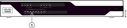
A Wireless Local Area Network (WLAN) implements a flexible data communication system frequently augmenting rather than replacing a wired LAN within a building or campus. WLANs use radio frequency to transmit and receive data over the air, minimizing the need for wired connections. Figure 1-1 shows the Cisco 812 ISR.
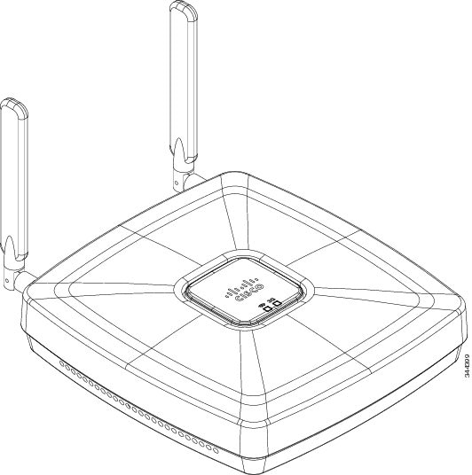
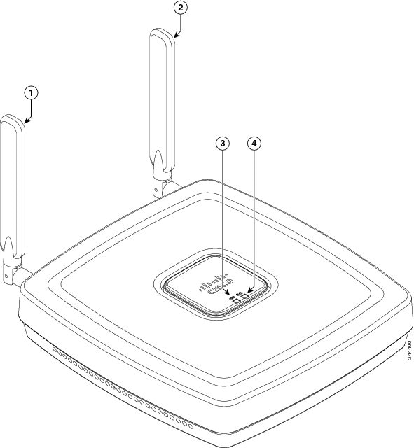
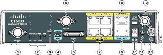
Figure 1-2 shows the 3G antenna and LEDs display.
Figure 1-2 Cisco 812 ISR 3G and LEDs Display
|
|
|
||
|
|
|
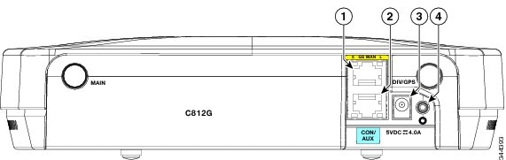
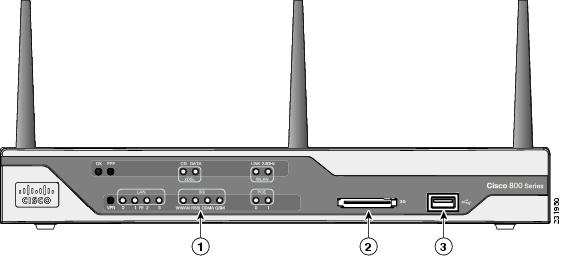
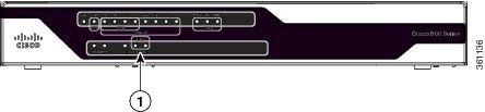
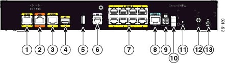
Figure 1-3 shows the I/O side of the Cisco 812 ISR.
Figure 1-3 Cisco 812 ISR I/O Side
|
|
|
||
|
|
|
Hardware Features
The Cisco 812 ISR supports the following hardware features:
Note![]() The WAAS Express feature is not supported. This feature will be supported for 3G and 4G interfaces with later IOS releases.
The WAAS Express feature is not supported. This feature will be supported for 3G and 4G interfaces with later IOS releases.
Platform Features
The Cisco 812 ISR has the following platform features:
- 1x GE Enabled WAN (1000/100/10 Base T)
- 2 TNC connectors for 3G main and diversity antenna (diversity antenna multiplexed with GPS)
- 512 MB Compact Flash Memory
- 512 MB DRAM
- AC Power Brick (100–264 V and max 0.5 A)
- Optional PoE+ (802.3at Class 4) Power Splitter
- Built-in Grounding
- Ceiling and Wall Mounting Option
- LED indicators for the platform
Antenna
The Cisco 812 ISR supports 3G external antenna and WiFi embedded antenna.
The Cisco 812 ISR provides two standard panel-mount TNC connectors to support 3G. The main antenna is used for the primary 3G antenna. The second can be used as a diversity receive only 3G antenna or an amplified GPS antenna. See Figure 1-2 for the location of the antennas.
The Cisco 812 ISR supports Dual ports WiFi radios (802.11 a/b/g/n) with embedded 2x3 MIMO.
For compliance and safety information, see the Regulatory Compliance and Safety Information for the Cisco 800 Series and SOHO Series Routers.
LEDs
The Cisco 812 ISR has two LEDs located on the top side of the router. The 3G LED is located on the lower right side with respect to the Cisco logo. 3G LED supports multiple functions and colors. The WiFi LED is located on lower left side with respect to the Cisco logo. Table 1-1 describes the 3G LED for the Cisco 812 ISR.
|
|
||
|---|---|---|
|
|
|
|
|
|
||
| RSSI1 |
||
White, Green, Light Blue, or Blue (three blinks and then a long pause) |
||
White, Green, Light Blue, or Blue (two blinks and then a long pause) |
||
White, Green, Light Blue, or Blue (one blink and then a long pause) |
||
|
1.The LED colors of RSSI can be any of the four colors (White, Green, Light Blue, or Blue) listed under 3G service type. |
Table 1-2 describes the WiFi LED for the Cisco 812 ISR.
Memory
The Cisco 812 ISR supports 512 MB DRAM and 512 MB compact flash memory. The Host router software runs on the first core. The second core runs the WLAN Access Point software.
If WLAN is not supported in an SKU, all 512 MB DRAM memory is allocated to the first core. For the SKUs that support WLAN, 128 MB out of the 512 MB main memory is allocated to the second core.
If WLAN is not supported in an SKU, all 512 MB DRAM compact flash memory is allocated to the first core. For the SKUs that support WLAN, 64 MB out of the 512 MB main memory is allocated to the second core.
Power Supply
The following are power adapters supported in the Cisco 812 ISR:
The default configuration is AC adapter that supports up to 4 A of 5 VDC current. The supported AC power adapter is PWR2-20W-AC that has a nominal input voltage of 100 to 240 VAC.
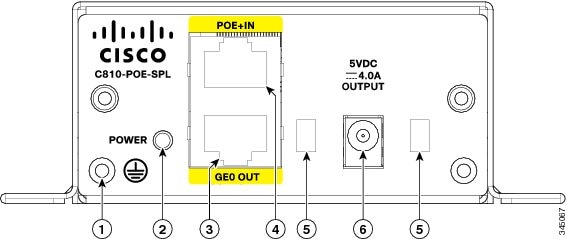
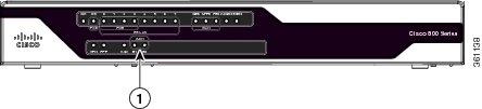
The Cisco PoE+ splitter (C810-POE-SPL) splits PoE+ into power and GE. It has connectors built into the power supply at both input and output so cables can be used at desired length as an option. Figure 1-4 shows the I/O side of the PoE+ splitter.
Figure 1-4 PoE+ Splitter I/O Side
|
|
|
||
|
|
|
||
|
|
|
SKU Information
Table 1-3 lists the different SKUs available for the Cisco 812 ISR. The AP802-AGN-X-K9 (WLAN PID) is integrated as part of the router for the SKUs that support WLAN and is not orderable separately.
Cisco 819 Series
This section provides an overview of the features available for the Cisco 819 and Cisco 819H Integrated Services Routers (ISRs) and contains the following sections:
Note![]() Cisco 819 is used to refer to Cisco 819HG, Cisco 819G, Cisco 819H, Cisco 819GW, Cisco 819HGW, Cisco 819HWD, Cisco 819HG-4G, and Cisco 819G-4G ISRs unless specifically called out otherwise.
Cisco 819 is used to refer to Cisco 819HG, Cisco 819G, Cisco 819H, Cisco 819GW, Cisco 819HGW, Cisco 819HWD, Cisco 819HG-4G, and Cisco 819G-4G ISRs unless specifically called out otherwise.
Note![]() This product is a Class 1 Outside Plant (OSP) as per Telcordia GR-3108.
This product is a Class 1 Outside Plant (OSP) as per Telcordia GR-3108.
Note![]() For compliance and safety information, see Regulatory Compliance and Safety Information Roadmap that ships with the router and Regulatory Compliance and Safety Information for Cisco 800 Series and SOHO Series Routers.
For compliance and safety information, see Regulatory Compliance and Safety Information Roadmap that ships with the router and Regulatory Compliance and Safety Information for Cisco 800 Series and SOHO Series Routers.
General Description
The Cisco 819 Integrated Services Router, part of the Cisco Integrated Services Routers Generation 2 (ISR G2) Family designed in compact hardened and non-hardened form factors, is the smallest Cisco IOS Software router with support for integrated fourth-generation (4G LTE) and third-generation (3G) wireless WAN (mobile broadband backhaul). The Cisco 819GW now supports Dual 802.11 a/b/g/n radios WiFi. The Cisco 819 ISR machine-to-machine gateway provides a rapidly deployable, highly available, reliable, and secure solution into machine-to-machine applications for financial, telemetry, utility, retail, industrial automation, and transportation with comprehensive management capability. Transparently integrated into Cisco IOS Software as an enterprise-class feature, the Cisco 819 Hardened ISR provides highly secure data, voice, and video communications to stationary and mobile network nodes across wired and wireless links.
Available in both non-hardened (Cisco 819G) and hardened (Cisco 819HG) versions, the Cisco 819 supporting 4G LTE and 3G wireless WAN (WWAN) speeds offers a cost-effective, rapidly deployable, reliable, and secure primary or backup solution. With support for industrial-grade components, the hardened Cisco 819HG extends the ISR machine-to-machine gateway footprint and provides the flexibility for deployment in many different stationary and mobile environments where space, heat dissipation, exposure to extreme temperatures, harsher environments, and low power consumption are critical factors. For mobile applications, Mobile IP delivers transparent roaming across multiple wireless networks capable of covering wide geographic areas.
The Cisco 819 ISR is a standard form factor with a commercial operating range. The 3G Cisco 819 ISRs support the 3G speeds (High-Speed PacketAccess Plus [HSPA+] enabling up to 4G speeds and Evolution Data Optimized [EVDO Rev A]). They are backward-compatible with High-Speed Packet Access (HSPA), Universal Mobile Telecommunications Service (UMTS), Enhanced Data Rates for Global Evolution (EDGE), General Packet Radio Service (GPRS), and EVDO Rev 0/1xRTT.
The 4G LTE C819 supports the latest Third-Generation Partnership Project (3GPP) Release 8 LTE standards. The Cisco 4G multimode LTE WWAN C819 provides persistent and reliable LTE connectivity with fallback and transparent handoff to earlier technologies. The Cisco 819HG-4G and Cisco 819G-4G support multimode 4G LTE and have embedded Sierra Wireless multimode modem.
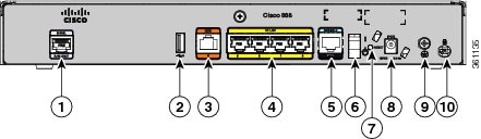
The Cisco 819 ISR is a desktop form factor with built-in wall-mount features, floor mount, and DIN rail mount features in selected SKUs. These routers are powered by an external AC power or optional DC adapter. Figure 1-5 shows the Cisco 819HG ISR.
The Cisco 819GW ISRs support WiFi radios with a higher memory density and a new barrel-type power connector. A Wireless Local Area Network (WLAN) implements a flexible data communication system frequently augmenting rather than replacing a wired LAN within a building or campus. WLANs use radio frequency to transmit and receive data over the air, minimizing the need for wired connections. Figure 1-6 shows the Cisco 819HGW ISR.
The Cisco 819GW ISRs have the following additional features:
Figure 1-5 Cisco 819HG Integrated Services Router
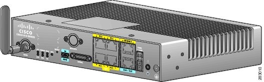
Figure 1-6 Cisco 819HGW Integrated Services Router
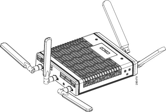
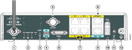
Figure 1-7 shows the front panel details of the Cisco 819HG ISR.
Figure 1-7 Cisco 819HG ISR Front Panel
|
|
|
||
|
|
|
||
|
|
|
||
|
|
|
||
|
|
|
||
|
|
|
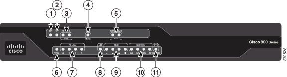
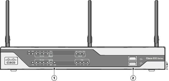
Figure 1-8 shows the front panel details of the Cisco 819HGW ISR.
Figure 1-8 Cisco 819HGW ISR Front Panel
|
|
|
||
|
|
|
||
|
|
|
||
|
|
|
||
|
|
|
||
|
|
|
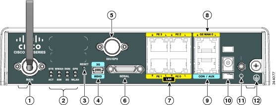
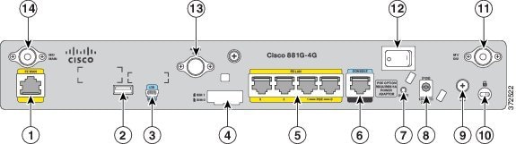
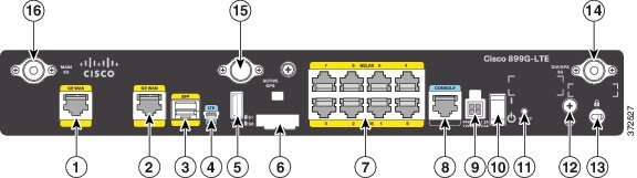
Figure 1-9 shows the front panel details of the Cisco 819 4G LTE ISR.
Figure 1-9 Cisco 819 4G LTE ISR Front Panel
|
|
|
||
|
|
|
||
|
|
|
||
|
|
|
||
|
|
|
||
|
|
|
||
|
|
|
SKU Information
Table 1-4 lists the different 3G SKUs available for the Cisco 819HG and Cisco 819G ISRs. All SKUs support external antenna.
Table 1-5 lists the different SKUs available for the Cisco 819HGW, Cisco 819H, and Cisco 819HWD ISRs.
Table 1-6 lists the different 4G LTE SKUs available for the Cisco 819HG and Cisco 819G ISRs.
Re-branding of C8xx-B and EHWIC-3G-EVDO-B
The C881G-B-K9, C819G-B-K9, and EHWIC-EVDO-B (Bharat) SKUs are introduced as an umbrella SKU to cover BSNL, Tata, and Reliance service providers in India.
Software based mechanism is introduced to identify specific carrier.
Carrier ID and name are displayed under "show cellular <unit> hardware".
The software mechanism is backward compatible with other existing CDMA SKUs such as HWIC-3G-CDMA(-S,-V) and PCEX-3G-CDMA(-S,-V).
15.3(2)T, 15.3(3)M or later. New MIB objects for carrier ID and name will be introduced in later release.
Hardware Features
This section provides an overview of the following hardware features for the Cisco 819 ISR.
- Platform Features for Cisco 819 ISRs
- Antennas
- Power Switch
- Reset Button
- LEDs
- Memory
- Embedded 3G Modem
- Embedded 4G LTE Modem
- SIM Card
- Supported Cisco Antennas and Cables
- Serial Port
- Power Supply
- Accessories
Note![]() The WAAS Express feature is not supported in 3G and 4G interfaces. However, the WAAS Express feature is supported on the Cisco 819H platform with other type of interfaces.
The WAAS Express feature is not supported in 3G and 4G interfaces. However, the WAAS Express feature is supported on the Cisco 819H platform with other type of interfaces.
Platform Features for Cisco 819 ISRs
Table 1-7 lists the platform features comparison for the Cisco 819 ISRs.
|
|
|
|
|
|
|---|---|---|---|---|
Dual 802.11 a/b/g/n Radios with Cisco DFS, CleanAir, and Client Link support |
||||
Real Time Clock (RTC)2 |
||||
|
2.A real-time clock (RTC) with battery backup provides date and time when the system is powered on. The RTC is used to verify the validity of the Certification Authority stored on the router. |
Antennas
The Cisco 819 3G routers provide two standard panel-mount TNC connectors to support the 3G antenna and the diversity and GPS external antenna. The main antenna is used for the primary 3G antenna. The second can be used as a diversity receive only 3G antenna or GPS antenna that does not require power supply from the router.
The Cisco 819 4G routers provide two standard panel-mount TNC connectors on the router front panel for the main and diversity antennas. The main antenna connector is used for the primary 4G antenna. The second antenna connector can be used as a diversity receive only 4G antenna. An SMA connector for active GPS antenna is also available on the front panel of the router.
The Cisco 819HGW and Cisco 819HWD ISRs also support Cisco WiFi external antennas. See the “Supported Cisco Antennas and Cables” section for more information.
The external WiFi antenna is used to support better WiFi coverage. All external antenna supports the following:
Power Switch
The power switch shuts down the router. A power switch lock is available to prevent accidental turning off of the router in the hardened SKUs.
Reset Button
The Reset button resets the router configuration to the default configuration set by the factory. To restore the router configuration to the default configuration set by the factory, use a standard size #1 paper clip with wire gauge 0.033 inch or smaller and simultaneously press the reset button while applying power to the router.
LEDs
The LEDs are located on the front panel of the router. Table 1-8 describes the 3G LEDs for the Cisco 819 ISR.
|
4.There is only one LED to indicate the status of two SIMs. A one-blink pattern represents the status of the SIM in slot 0, followed by a two-blink pattern for the SIM in slot 1. |
Table 1-9 describes the WLAN LEDs for the Cisco 819HGW and Cisco 819HWD ISRs.
Table 1-10 describes the 4G LTE LEDs for the Cisco 819 ISR.
Memory
The Cisco 819HG and Cisco 819G ISRs uses non-upgradable flash memory and main memory. The onboard flash memory contains the Cisco IOS software image and the boot flash contains the ROMMON boot code. Table 1-11 lists the memory requirements for Cisco 819 ISRs.
|
|
|
|
|
|---|---|---|---|
Embedded 3G Modem
The 3G cellular interface is the primary WAN data link, but it can also be used as a backup data link. The 3G technology is third-generation wide-area cellular technology that is used in broadband wireless data in a mobile environment.
Embedded 4G LTE Modem
The Cisco 819HG-4G and Cisco 819G-4G routers have an embedded 4G LTE modem provided by Sierra Wireless. The Verizon SKUs come with an MC7750 modem, the AT&T SKUs come with an MC7700 modem, and the Global SKUs come with an MC7710 modem.
SIM Card
Table 1-12 lists the SIM Card slots available for Cisco the 819 ISRs.
|
|
|
|
|---|---|---|
Supported Cisco Antennas and Cables
The Cisco 819 ISR provides two standard panel-mount TNC connectors to support the 3G antenna and the diversity and GPS external antenna. The main antenna is used for the primary 3G antenna. The second can be used as a diversity receive only 3G antenna or GPS antenna that does not require power supply from the router.
Note![]() A Lightning Arrestor must be used when you install antenna outdoor. Note that the center conductor is not protected under 200V (sparkover voltage nominal value).
A Lightning Arrestor must be used when you install antenna outdoor. Note that the center conductor is not protected under 200V (sparkover voltage nominal value).
Table 1-13 lists the Cisco 3G antennas that are supported for use on Cisco 819 ISRs.
Table 1-14 lists the supported Cisco WiFi antenna for Cisco 819HGW and Cisco 819HWD ISRs.
Table 1-15 lists the Cisco 4G LTE antennas that are supported for use on Cisco 819 ISRs.
|
|
|
|
|
|---|---|---|---|
Multiband dipole antenna. For more information, see Cisco 4G/3G Omnidirectional Dipole Antenna (4G-LTE-ANTM-D). |
|||
Multiband omnidirectional ceiling-mount antenna. For more information, see Cisco 4G Indoor Ceiling-Mount Omnidirectional Antenna (4G-ANTM-OM-CM). |
|||
Multiband outdoor omnidirectional stick antenna. For more information, see Cisco Outdoor Omnidirectional Antenna for 2G/3G/4G Cellular (ANT-4G-OMNI-OUT-N). |
|||
Low-profile outdoor saucer antenna. For more information, see Cisco Integrated 4G Low-Profile Outdoor Saucer Antenna (ANT-4G-SR-OUT-TNC). |
|||
4G lightning arrestor kit for use on Cisco 4G wireless devices. For more information, see Lightning Arrestor for the Cisco 1240 Connected Grid Router. |
|||
4G lightning arrestor kit for use on Cisco 4G wireless devices. For more information, see Cisco 4G Lightning Arrestor (4G-ACC-OUT-LA). |
Table 1-16 to Table 1-18 list the extension cables for use with 3G, WiFi, and 4G LTE antennas. The tables include the insertion loss information for the ultra-low-loss (ULL) LMR 400 extension cables.
|
|
|
|
|
|---|---|---|---|
|
|
|
|
|
|---|---|---|---|
|
|
|
|
|
|
|
|---|---|---|---|---|---|
|
|
Serial Port
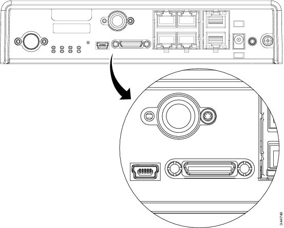
The Cisco standard High Speed Smart Serial 12-in-1 connector allows the highest flexibility of connections to various DTE/DCE devices. The 12-in-1 serial interface pins connect to the FPGA. The FPGA configures the pin directions based on the cable type used. Figure 1-10 shows the magnified view of the 12-in-1 serial port. For more information, see About Serial Connections.
Figure 1-10 12-in-1 Serial Port
Power Supply
All SKUs require a 5 VDC power source. Cisco 819HG and Cisco 819G ISRs have a self-locking Molex mini-fit connector. Cisco 819HGW and Cisco 819HWD ISRs use a 5.5 mm barrel-type connector with separate locking clip. An external AC power adapter is supported by default. The optional external power adapters are available to support a variety of DC power sources, suitable for fixed, vehicle, or railway installations. The 5 VDC power input of the router is protected from over-voltage up to 20 VDC. The router will not power up if excessive voltage (for example, a 12 VDC adapter) is connected.
The default configuration includes an external AC adapter that supplies up to 20 W of power. The AC power connection is a two-pin IEC 320 C8 receptacle. A mating AC power cord is supplied. The AC adapter does not provide chassis grounding to the router. A 1.3-meter long output cable connects to the router.
The optional external DC power adapters are available for 12 VDC and 24 VDC nominal vehicle power.
- 12 VDC vehicle adapter has a 10 VDC to 36 VDC operating range
- 24 VDC vehicle adapter has an 18 VDC to 75 VDC operating range
- 48 VDC vehicle adapter has an 20 VDC to 60 VDC operating range
The vehicle power adapters may be used for fixed or mobile installations. They do not provide electrical isolation; the input negative is connected to the output negative (chassis ground). Input cable is 350 millimeter long with stripped and tinned bare wire connections. The input positive connection is a white wire and the input negative is a black wire.
The optional external power adapters meeting Railway Standards are available from a third-party supplier, Martek Power. Contact Martek Power directly to order and for detailed specifications. The use of Martek Power adapters listed in the “Supported Power Adapters” section will maintain Cisco warranty and support of the router; the power adapter itself is covered by Martek warranty. Input connection to the railway adapters is by a 350 millimeter long wire with stripped and tinned bare wire connection. A 1.3-meter long output cable connects to the router.
Accessories
Table 1-19 lists the accessories available for the Cisco 819 ISRs. For a complete list of SKUs that support these accessories, see the “Platform Features for Cisco 819 ISRs” section.
|
|
|
|---|---|
Cisco 860, 880, 890 Series
This section provides an overview of the features available for the Cisco 860 series, Cisco 880 series, and Cisco 890 series Integrated Services Routers (ISRs), and contains the following sections:
- General Description
- Cisco 860 Series ISRs
- Cisco 860VAE Series ISRs
- Cisco 860VAE-W-A-K9, Cisco 860VAE-W-E-K9, and Cisco 860VAE-POE-W-A-K9 ISRs
- Cisco 880 Series ISRs
- Cisco C881, C886, and C887 Series ISRs
- Cisco C880 Series and Cisco C890 Series 4G LTE Integrated Services Routers
- Cisco 890 Series Integrated Service Routers
- Cisco C891 Series ISRs
- Hardware Features
Note![]() For compliance and safety information, see Regulatory Compliance and Safety Information Roadmap that ships with the router and Regulatory Compliance and Safety Information for Cisco 800 Series.
For compliance and safety information, see Regulatory Compliance and Safety Information Roadmap that ships with the router and Regulatory Compliance and Safety Information for Cisco 800 Series.
Note![]() Some illustrations in this document show a wireless router. Both wireless and nonwireless models are available in the Cisco 860 series, Cisco 880 series, and Cisco 890 series ISRs. Port and feature locations are similar for both wireless and nonwireless routers.
Some illustrations in this document show a wireless router. Both wireless and nonwireless models are available in the Cisco 860 series, Cisco 880 series, and Cisco 890 series ISRs. Port and feature locations are similar for both wireless and nonwireless routers.
Note![]() Throughout this document the term VDSL refers to support for VDSL2 (ITU G.993.2) and ADSL refers to support for ADSL, ADSL2, & ADSL2+ (ITU G.992.1, G.992.3, & G.992.5).
Throughout this document the term VDSL refers to support for VDSL2 (ITU G.993.2) and ADSL refers to support for ADSL, ADSL2, & ADSL2+ (ITU G.992.1, G.992.3, & G.992.5).
General Description
The Cisco 860 series, Cisco 880 series, and Cisco 890 series ISRs provide data, voice, Wi-Fi CERTIFIED™ wireless access point (AP), integrated Virtual Private Network (VPN), and backup capabilities to corporate teleworkers and to remote and small offices with fewer than 20 users. These routers are capable of bridging and multiprotocol routing between LAN and WAN ports. The routers provide advanced features, such as high speed DSL (G.SHDSL, ADSL, or VDSL), 802.11n, quality of service (QoS), firewall, antivirus protection, and Secure Socket Layer (SSL). The Cisco 860VAE, 886VA and 887VA series routers have the additional capability of DSL Multi-mode (VDSL/ADSL).
The Cisco 860 series, Cisco 880 series, and Cisco 890 series ISRs have a desktop form factor with built-in wall-mount features. The Cisco 890 series ISRs also have optional rack-mount features. These ISRs are powered by an external power supply adapter. The various models differ in the WAN interface and features that they support.
Cisco 860 Series ISRs
The Cisco 860 series ISRs are fixed-configuration data routers that support the following features:
- An integrated 4-port 10/100 Ethernet switch for connecting to the LAN
- A10/100 Fast Ethernet (FE) port for connecting to the WAN.
- Optional, embedded Wi-Fi CERTIFIED™, 802.11b/g/n-compliant wireless AP
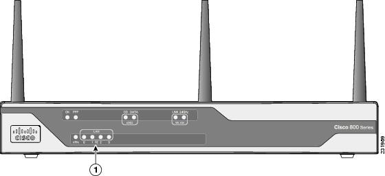
Figure 1-7 shows the front panel details of the Cisco 860 wireless router.
Figure 1-11 Front Panel of the Cisco 860 Series Wireless ISR
|
|
|
Figure 1-12 shows the back panel details of the Cisco 861 wireless (861W) ISR. Nonwireless routers do not have antennas on the back panel. However, the feature locations are similar for all Cisco 860 series routers.
Figure 1-12 Back Panel of the Cisco 861W ISR
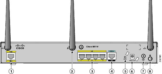
|
|
|
||
|
|
Antenna—captive omnidirectional dipole WLAN antenna (wireless models only) |
|
|
|
|
|
||
|
|
|
Cisco 860VAE Series ISRs
The Cisco 860VAE series ISRs are fixed-configuration data routers. This section describes the features of the products in this series.
Interfaces
Table 1-20 describes the interfaces of the Cisco 860VAE series routers.
|
|
|
|||
|---|---|---|---|---|
|
|
|
|
|
|
4 FE6 switch ports |
||||
1 GE7 switch port |
||||
|
|
Note![]() The Cisco 866VAE, 867VAE, 866VAE-K9, and 867VAE-K9 routers each have two WAN ports. Only one of the two ports can be active at any given time.
The Cisco 866VAE, 867VAE, 866VAE-K9, and 867VAE-K9 routers each have two WAN ports. Only one of the two ports can be active at any given time.
Table 1-21 describes the interfaces of the C860VAE series routers.
|
|
|
||
|---|---|---|---|
|
|
|
|
|
3 FE8 switch ports |
|||
2 GE9 switch port |
|||
|
|
IOS Images
Table 1-22 describes the IOS images included in Cisco 860VAE series routers.
|
|
|
|||
|---|---|---|---|---|
|
|
|
|
|
|
Table 1-23 describes the IOS images included in C860VAE series routers.
|
|
|
||
|---|---|---|---|
|
|
|
|
|
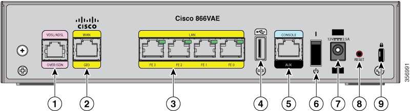
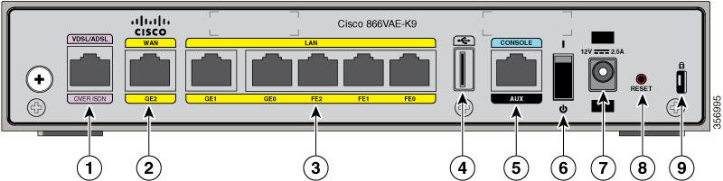
Figure 1-13 shows the front panel details of the Cisco 866VAE, Cisco 867VAE, Cisco 866VAE-K9, and Cisco 867VAE-K9 integrated services routers (ISRs).
Figure 1-13 Front Panel of the Cisco 860VAE series ISR
|
|
|
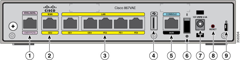
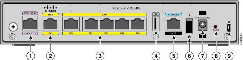
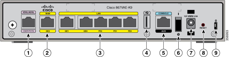
Figure 1-14 shows the front panel details of the C867VAE, C866VAE-K9, and C867VAE-K9 integrated services routers (ISRs).
Figure 1-14 Front Panel of the C860VAE series ISR
|
|
|
Figure 1-15 shows the back panel details of the Cisco 866VAE ISR.
Figure 1-15 Back Panel of the Cisco 866VAE ISR
|
|
xDSL port10 |
|
|
|
|
|
||
|
|
|
||
|
|
|
||
|
|
|
|
|
Figure 1-16 shows the back panel details of the C867VAE ISR.
Figure 1-16 Back Panel of the C867VAE ISR
|
|
xDSL port11 |
|
|
|
|
|
||
|
|
Ethernet LAN GE and FE interfaces (GE0, GE1 interfaces and FE0 through FE2 interfaces) |
|
|
|
|
|
||
|
|
|
|
|
Figure 1-17 shows the back panel details of the Cisco 867VAE-K9.
Figure 1-17 Back Panel of the Cisco 867VAE-K9 ISR
|
|
|
||
|
|
|
||
|
|
Ethernet LAN GE and FE interfaces (GE0 interface and FE0 through FE3 interfaces) |
|
|
|
|
|
||
|
|
|
Figure 1-18 shows the back panel details of the C866VAE-K9.
Figure 1-18 Back Panel of the C866VAE-K9 ISR
|
|
|
||
|
|
|
||
|
|
Ethernet LAN GE and FE interfaces (GE0, GE1 interfaces and FE0 through FE2 interfaces) |
|
|
|
|
|
||
|
|
|
Figure 1-19 shows the back panel details of the C867VAE-K9.
Figure 1-19 Back Panel of the C867VAE-K9 ISR
|
|
|
||
|
|
|
||
|
|
Ethernet LAN GE and FE interfaces (GE0, GE1 interfaces and FE0 through FE2 interfaces) |
|
|
|
|
|
||
|
|
|
Cisco 860VAE-W-A-K9, Cisco 860VAE-W-E-K9, and
Cisco 860VAE-POE-W-A-K9 ISRs
This section provides a hardware overview of the following Cisco 860VAE Series Integrated Services Routers (ISRs):
Model-Specific Features
Table 1-24 describes the features specific to each of these router models:
|
|
|
|
|
|
|---|---|---|---|---|
Common Features
The following key features are common to each of these router models:
- Dual WAN interface (Gigabit Ethernet [GE] and dual-mode ADSL2+ /VDSL2)
- 2.4 GHz wireless LAN (WLAN) interface
- Five Layer 2 LAN switches: two Gigabit Ethernet and three Fast Ethernet
- One USB 2.0 port in high-speed host mode
- One RJ-45 console port (RS-232 interface)
- Support for up to 512 MB DRAM using DDR in 16-bit mode
- Support for 8 MB Serial Peripheral Interface Bus (SPI) flash memory for boot and 128 MB NAND flash memory for storing IOS
- Reset/Recovery switch
- Silent convection cooling—no fan
External Interfaces
Figure 1-20 shows the back I/O panel of the Cisco 867VAE-POE-W-A-K9 series router.
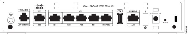
Table 1-25 describes the external interfaces included with these router models.
|
|
|
|
|
|
|---|---|---|---|---|
FE012 |
||||
|
12.Provides Power-over-Ethernet (PoE) for the Cisco C867VAE-POE-W-A-K9. |
Note![]() For the Cisco C867VAE-POE-W-A-K9, Power-over-Ethernet (PoE) is available using port FE0, with a 60-W power supply.
For the Cisco C867VAE-POE-W-A-K9, Power-over-Ethernet (PoE) is available using port FE0, with a 60-W power supply.
USB Interface
The USB 2.0 interface enables:
- Transferring data using a USB flash token (USB memory stick) for system recovery and other tasks.
- Cisco IOS software boot from USB.
Use only the following Cisco USB 2.0 flash tokens:
Note![]() The USB 2.0 port cannot be used for connecting external devices or as a console for devices other than those specified in the USB eToken Device and USB Flash Features Support Data Sheet, available at:
The USB 2.0 port cannot be used for connecting external devices or as a console for devices other than those specified in the USB eToken Device and USB Flash Features Support Data Sheet, available at:
http://www.cisco.com/en/US/prod/collateral/modules/ps6247/product_data_sheet0900aecd80232473.html
LED Indicators
These router models include LED indicators on the back panel for each LAN port, and additional LED indicators on the front panel of the unit.
On the back panel of the unit, each LAN port includes an LED indicator. Table 1-26 describes the LED indicators.
|
|
|
|
|---|---|---|
|
|
||
|
|
||
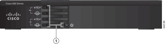
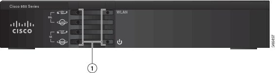
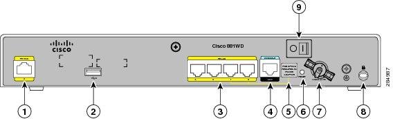
The front panel includes several LED indicators. Figure 1-21 shows the location of the LED indicators.
Figure 1-21 Front Panel LED Indicators
|
|
|
Table 1-27 describes the LED indicators.
Cisco 880 Series ISRs
The Cisco 880 series ISRs have data and voice capabilities. They have the following features:
- Integrated 4-port 10/100 Ethernet switch for connecting to the LAN
- 10/100 FE, VDSLoPOTS, ADSL over POTS, ADSL over ISDN, DSL Multi-mode (VDSL/ADSLoPOTS, VDSL/ADSLoISDN Cisco VA models only), or G.SHDSL port for connecting to the WAN
- Optional embedded Wi-Fi CERTIFIED™, 802.11b/g/n-compliant wireless AP
- Optional 2-port Power over Ethernet (PoE)
Note![]() The Cisco 880 series ISRs can include an optional PoE module that provides power to 802.3af-compliant devices connected to ethernet ports 0 and 1. If this feature was not configured with the factory order, you must order and install it to enable the PoE function.
The Cisco 880 series ISRs can include an optional PoE module that provides power to 802.3af-compliant devices connected to ethernet ports 0 and 1. If this feature was not configured with the factory order, you must order and install it to enable the PoE function.
- DIMM expansion socket that can accept up to 512 MB of additional memory, for a total of 768 MB system memory
Cisco 880 Series Data Routers
The Cisco 880 series data routers provide integrated VPN, embedded Wi-Fi CERTIFIED™, 802.11b/g/n-compliant wireless AP, 3G, and backup capabilities. Figure 1-22 through Figure 1-25 show the features available on Cisco 880 series data routers. Some of the features shown may not be available on your router.
Depending on the router model, the primary WAN port can be G.SHDSL, VDSLoPOTS, VDSL/ADSL over ISDN, VDSL/ADSL over POTS, or 10/100 FE. See the Cisco 880 Series Integrated Services Routers data sheet for the WAN interface that is supported on your router.
Figure 1-22 shows the front panel details of the Cisco 880 wireless data router. The USB port and the 3G card slot are located on the front panel.
Figure 1-22 Front Panel of the Cisco 880 Series Wireless Data Router
|
|
|
||
|
|
3G express card slot—Supports third-party13 3G card (Cisco 880G models only) |
|
|
13.See the Cisco 880 Series Integrated Services Routers data sheet for supported vendors. |
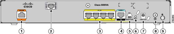
Figure 1-23 shows the back panel details of the Cisco 886VA data router.
Figure 1-23 Back Panel of the Cisco 886VA Router
|
|
Data BRI14 0 |
|
|
|
|
|
||
|
|
4-port 10/100 Ethernet switch15 |
|
|
|
|
|
||
|
|
|
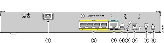
Figure 1-24 shows the back panel details of the Cisco 887VA and 886VA-M data router.
Figure 1-24 Back Panel of the Cisco 887VA and 887VA-M Router
|
|
Primary WAN port—VDSL/ADSL over POTS16 |
|
|
|
|
4-port 10/100 Ethernet switch17 |
|
|
|
|
|
||
|
|
|
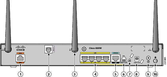
Figure 1-25 shows the back panel details of the Cisco 888W data router. Nonwireless routers do not have antennas on the back panel. However, the feature locations are similar across all Cisco 880 series data routers.
Figure 1-25 Back Panel of the Cisco 888W Data Router
|
|
|
PoE power connector for optional PoE module18 |
|
|
|
Primary WAN port19—G.SHDSL, VDSLoPOTS, ADSLoPOTS, ADSLoISDN, or 10/100 FE |
|
|
|
|
Antenna—captive omnidirectional dipole WLAN antenna (wireless models only) |
|
|
|
|
|
||
|
|
|
|
18.The Cisco 880 series ISRs can include an optional PoE module that provides power to 802.3af-compliant devices connected to ethernet ports 0 and 1. If this feature was not configured with the factory order, you must order and install it to enable the PoE function. 19.Depending on the router model, the primary WAN port can be G.SHDSL, VDSLoPOTS, or 10/100 FE. The VDSLoPOTS port is in the same location as the G.SHDSL port. The 10/100 FE WAN port is located at the bottom left corner. See Figure 1-12 for the location of the 10/100 FE WAN port. |
Cisco 880 Series Voice and Data Routers
The Cisco 880 series voice and data routers provide both voice and data ports. The voice ports managed voice services that interface with Foreign Exchange Station (FXS), Foreign Exchange Office (FXO), or BRI connections.
Cisco 881 SRST and Cisco 888 SRST
Figure 1-26, Figure 1-27, and Figure 1-28 show the features available on the Cisco 881 SRST and Cisco 888 SRST routers. The features available vary, depending on the router model. Some features may not be available on your router.
Depending on the router model, the primary WAN port can be either G.SHDSL or 10/100 FE. See the Cisco 880 Series Integrated Services Routers data sheet for the WAN interface and voice ports that are supported on your router.
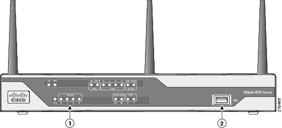
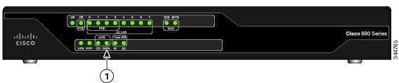
Figure 1-26 shows the front panel details of the Cisco 881 SRST and Cisco 888 SRST wireless voice router.
Figure 1-26 Front Panel of the Cisco 881 SRST and Cisco 888 SRST Wireless Voice Router
|
|
|
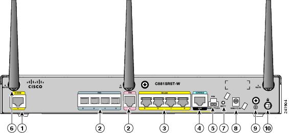
Figure 1-27 shows the back panel details of the Cisco 881SRST-W voice router.
Figure 1-27 Back Panel of the Cisco C881SRST-W Voice Router
|
|
Primary WAN port20—10/100 FE |
|
Antenna—captive wireless omnidirectional dipole WLAN antenna (wireless models only) |
|
|
Voice ports—four FXS21/DID22 ports, one FXO23 port with TBP24 power failover |
|
|
|
|
4-port 10/100 Ethernet switch25 |
|
|
|
|
|
||
|
|
PoE power connector for optional PoE module26 |
|
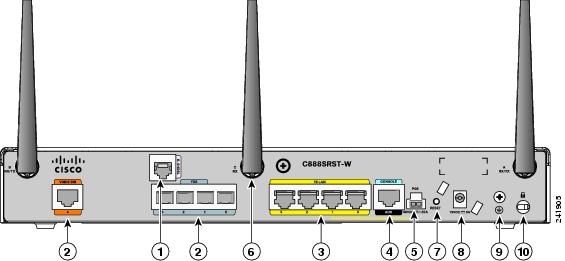
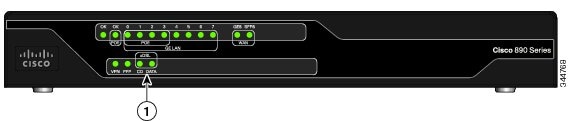
Figure 1-28 shows the back panel details of the Cisco 888SRST-W voice router.
Figure 1-28 Back Panel of the Cisco C888SRST-W Voice Router
|
|
Primary WAN port27—G.SHDSL |
|
Antenna—captive wireless omnidirectional dipole WLAN antenna (wireless models only) |
|
|
|
||
|
|
4-port 10/100 Ethernet switch28 |
|
|
|
|
|
||
|
|
PoE power connector for optional PoE module29 |
|
Cisco 881-V, Cisco 887VA-V, and Cisco 887VA-V-W
Figure 1-29, Figure 1-30, and Figure 1-31 show the features available on the Cisco 881-V and Cisco 887VA-V routers. The features available vary, depending on the router model. Some features may not be available on your router.
The Cisco 881-V and Cisco 887VA-V voice and data series gives you the flexibility to use either FXS or BRI voice ports. However, the number of concurrent calls that can be supported by the router is limited by the codec complexity setting on the router. Table 1-28 lists the maximum number of calls that is supported when the codec complexity command is configured for Flexible, Medium or High complexity.
Note![]() Configuring the codec complexity setting to support secure calls uses DSP resources, but does not affect the maximum number of supported calls.
Configuring the codec complexity setting to support secure calls uses DSP resources, but does not affect the maximum number of supported calls.
|
|
|
|
|
|---|---|---|---|
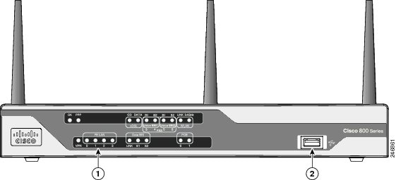
Figure 1-29 shows the front panel details of the Cisco 881-V, Cisco 887VA-V, and Cisco 887VA-V-W.
Figure 1-29 Front Panel of the Cisco 881-V, Cisco 887VA-V, and Cisco 887VA-V-W Routers
|
|
|
Figure 1-30 shows the back panel for the Cisco 887VA-V-W router. The Cisco 887VA-V (non-wireless) router does not have the antennas on the back panel.
Figure 1-30 Back Panel of the Cisco 887 VA-V Router
|
|
|
||
|
|
|
||
|
|
|
||
|
|
|
||
|
|
|
||
|
|
|
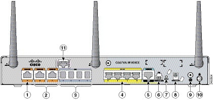
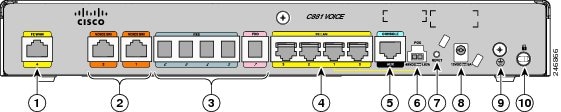
Figure 1-31 shows the back panel for the Cisco 881-V router.
Figure 1-31 Back Panel of the Cisco 881-V Router
|
|
|
||
|
|
|
||
|
|
|
||
|
|
|
||
|
|
|
Cisco 880 Series with Embedded WLAN Antennas
Some Cisco 880W, 880WD, and 880-WD ISRs have three embedded WLAN antennas.
These ISRs are fixed-platform routers that:
- Provide integrated VPN, embedded Wi-Fi CERTIFIED™, 802.11b/g/n-compliant wireless AP, and backup capabilities.
- Use single-band (2.4 GHz) WLAN cards or dual-band (2.4 GHz and 5 GHz) WLAN cards.
- Require a single external power supply: a 30-W power supply for non-POE-enabled routers or a 60-W power supply for POE-enabled routers.
- Have a fixed 512 MB of system memory.
For information on configuring the Cisco 880 series ISRs, see Cisco 880 Series Integrated Services Router Software Configuration Guide.
Cisco 887VA-WD
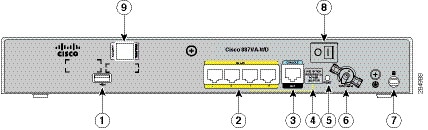
Figure 1-32 shows the front panel details of the C887VA-WD-A-K9 and C887VA-WD-E-K9 ISRs. The front panel has LEDs only. All the ports are in the back panel.
Figure 1-32 Front Panel of the C887VA-WD-A-K9 and C887VA-WD-E-K9 ISRs
Figure 1-33 shows the back panel details of the C887VA-WD-A-K9 and C887VA-WD-E-K9 ISRs.
Figure 1-33 Back Panel of the C887VA-WD-A-K9 and C887VA-WD-E-K9 ISRs
|
|
|
||
|
|
|
||
|
|
|
||
|
|
Note No separate PoE power supply is required for routers with embedded WLAN antennas. For information on system power supply requirements when PoE is enabled, see the “Power over Ethernet Module” section. |
|
|
|
|
|
C881WD
Figure 1-34 shows the front panel details of the C881WD-A-K9 and C881WD-E-K9 ISRs. The front panel has LEDs only. All the ports are in the back panel.
Figure 1-34 Front Panel of the C881WD-A-K9 and C881WD-E-K9 ISRs
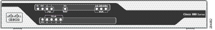
Figure 1-35 shows the back panel details of the C881WD-A-K9 and C881WD-E-K9 ISRs.
Figure 1-35 Back Panel of the C881WD-A-K9 and C881WD-E-K9 ISRs
|
|
|
||
|
|
|
||
|
|
|
||
|
|
|
||
|
|
Note No separate PoE power supply is required for routers with embedded WLAN antennas. For information on system power supply requirements when PoE is enabled, see the “Power over Ethernet Module” section. |
|
C881G-B/S/V-K9 ISRs
The C881G-B-K9, C881G-S-K9, and C881G-V-K9 ISRs are members of the Cisco 880 series data routers. These routers provide integrated Virtual Private Network (VPN), 802.11b/g/n-compliant wireless Access Point (AP), 3G, and backup capabilities.
For information on configuring Cisco 880 Series ISRs, see Cisco 880 Series Integrated Services Router Software Configuration Guide.
C881GW-S/V-A-K9 ISRs
The C881GW-S-A-K9 and C881GW-V-A-K9 ISRs are members of the Cisco 880G series data routers. These routers provide integrated VPN, embedded Wi-Fi CERTIFIED™, 802.11b/g/n-compliant wireless AP, 3G, and backup capabilities.
For information on configuring Cisco 880 Series ISRs, see Cisco 880 Series Integrated Services Router Software Configuration Guide.
C881G-U-K9 ISRs
The C881G-U-K9 ISR is a member of the Cisco 880 series data routers. These routers provide integrated Virtual Private Network (VPN), embedded Wi-Fi CERTIFIED™, 802.11b/g/n-compliant wireless Access Point (AP), 3G, and backup capabilities.
For information on configuring Cisco 880 Series ISRs, see Cisco 880 Series Integrated Services Router Software Configuration Guide.
HSPA+ Versions of the Fixed-Platform ISRs
The C881G+7-K9, C886VAG+7-K9, C887VAG+7-K9, C887VAMG+7-K9, C888EG+7-K9, C881GW+7-A-K9, C881GW+7-E-K9, C887VAGW+7-A-K9, and C887VAGW+7-E-K9 ISRs are members of the Cisco 880G series data routers. These routers provide integrated VPN, embedded Wi-Fi CERTIFIED™, 802.11b/g/n-compliant wireless AP, 3G, and backup capabilities.
For information on configuring Cisco 880 Series ISRs, see Cisco 880 Series Integrated Services Router Software Configuration Guide.
Cisco C881, C886, and C887 Series ISRs
Cisco C881, C886, and C887 Series ISRs offer broadband speed and simplified management to small businesses, small enterprise branches, and teleworkers. The Cisco C881, C886, and C887 Series ISR models have a lead-free, fanless chassis and are updated versions of the previous Cisco 881, 886, and 887 series (excluding 3G and wireless models).
Information provided in this section is applicable for the following models:
Table 1-29 provides information about important hardware specifications pertaining to Cisco C881, C886, and C887 Series Routers.
Table 1-29 Hardware Specifications of Cisco C881, C886, and C887 Series Routers
|
|
|
|---|---|
For detailed hardware specifications, see the Cisco 880 Series hardware data sheet at:
http://www.cisco.com/en/US/prod/collateral/routers/ps380/data_sheet_c78_459542_ps380_Products_Data_Sheet.html
Cisco C881 Router
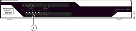
Figure 1-36 shows the front panel of the Cisco C881 Router.
Figure 1-36 Front Panel of the Cisco C881 Router
|
|
|
For detailed description about the LEDs on the Cisco C880 Series Routers, see the “LEDs” section.
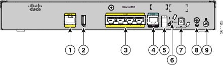
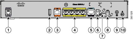
Figure 1-37 shows the back panel of the Cisco C881 Router.
Figure 1-37 Back Panel of the Cisco C881 Router
|
|
|
||
|
|
|
||
|
|
|||
|
|
|
||
|
|
|
For information on installing the Cisco C880 Series Routers, see :
http://www.cisco.com/en/US/docs/routers/access/800/860-880-890/hardware/installation/guide/2Install880-860.html
Cisco C886VA Router
Figure 1-38 shows the front panel of the Cisco C886VA Router.
Figure 1-38 Front Panel of the Cisco C886VA Router
|
|
|
For detailed description about the LEDs on the Cisco C880 Series Routers, see the “LEDs” section.
Figure 1-39 shows the back panel of the Cisco C886VA Router.
Figure 1-39 Back Panel of the Cisco C886VA Router

|
|
|
||
|
|
|
||
|
|
|
||
|
|
|
||
|
|
|
For information on installing Cisco C880 Series Routers, see:
http://www.cisco.com/en/US/docs/routers/access/800/860-880-890/hardware/installation/guide/2Install880-860.html
Cisco C886VAJ Router
Figure 1-40 shows the front panel of the Cisco C886VAJ Router.
Figure 1-40 Front Panel of the Cisco C886VAJ Router

|
|
|
For detailed description about LEDs on the Cisco 880 Series Router, see the “LEDs” section.
Figure 1-41 shows the back panel of the Cisco C886VAJ Router.
Figure 1-41 Back Panel of the Cisco C886VAJ Router
|
|
|
||
|
|
|
||
|
|
|
||
|
|
|
||
|
|
|
For information on installing Cisco C880 Series Routers, see:
http://www.cisco.com/en/US/docs/routers/access/800/860-880-890/hardware/installation/guide/2Install880-860.html
Cisco C887VA Router
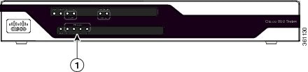
Figure 1-42 shows the front panel of the Cisco C887VA Router.
Figure 1-42 Front Panel of the Cisco C887VA Router
|
|
|
For detailed description about the LEDs on Cisco C880 Series Router, see the “LEDs” section.
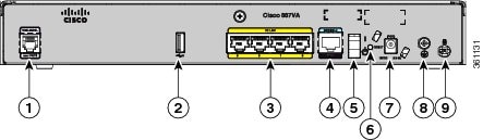
Figure 1-43 shows the back panel of the Cisco C887VA Router.
Figure 1-43 Back Panel of the Cisco C887VA Router
|
|
|
||
|
|
|
||
|
|
|
||
|
|
|
||
|
|
|
For information on installing Cisco C880 series routers, see the following link:
http://www.cisco.com/en/US/docs/routers/access/800/860-880-890/hardware/installation/guide/2Install880-860.html
Cisco C887VAM Router
Figure 1-44 shows the front panel of the Cisco C887VAM router:
Figure 1-44 Front Panel of the Cisco C887VAM Router

|
|
|
For detailed description about LEDs on Cisco C880 series router, see “LEDs” section.
Figure 1-45 shows the back panel of the Cisco C887VAM router.
Figure 1-45 Back Panel of the Cisco C887VAM Router

|
|
|
||
|
|
|
||
|
|
|
||
|
|
|
||
|
|
|
For information on installing the Cisco C880 Series Routers, see:
http://www.cisco.com/en/US/docs/routers/access/800/860-880-890/hardware/installation/guide/2Install880-860.html
Cisco C888 Integrated Services Router
The Cisco C888 Integrated Services Router (ISR) offers broadband speeds and simplified management to small businesses, enterprise small branches, and teleworkers. The Cisco C888 ISR supports multi mode G.SHDSL (EFM+ATM) WAN connectivity. The Cisco C888 ISR has a lead free, fanless chassis and it is an updated version of the previous Cisco 888 (888 A and 888 EA) ISR models.
Table 1-30 provides information about important hardware specifications pertaining to the Cisco C888 ISR.
Table 1-30 Hardware Specifications for Cisco C888 ISR
|
|
|
|---|---|
Note![]() If you change G.SHDSL mode from EFM to ATM or from ATM to EFM, you should reload the router.
If you change G.SHDSL mode from EFM to ATM or from ATM to EFM, you should reload the router.
Note![]() EFM auto mode is supported only on the first pair. EFM manual mode can be supported on all the 4 pairs.
EFM auto mode is supported only on the first pair. EFM manual mode can be supported on all the 4 pairs.
Note![]() Cisco C888 ISR does not support Inverse Multiplexing over ATM (IMA) mode.
Cisco C888 ISR does not support Inverse Multiplexing over ATM (IMA) mode.
For detailed hardware specifications, see the Cisco 880 Series hardware data sheet at:
http://www.cisco.com/en/US/prod/collateral/routers/ps380/data_sheet_c78_459542_ps380_Products_Data_Sheet.html
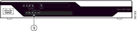
Figure 1-46 shows the front panel of the Cisco C888 Router:
Figure 1-46 Front Panel of the Cisco C888 Router
|
|
|
For detailed description about the LEDs on the Cisco 880 Series Routers, see information available at:
http://www.cisco.com/en/US/docs/routers/access/800/860-880-890/hardware/installation/guide/1Overview880-860.html#wp1147924
Figure 1-47 shows the back panel of the Cisco C888 Router.
Figure 1-47 Back Panel of the Cisco C888 Router
|
|
|
||
|
|
|
||
|
|
|
||
|
|
|
||
|
|
|
For information on installing Cisco 800 Series Routers, see the information available at:
http://www.cisco.com/c/en/us/td/docs/routers/access/800/hardware/installation/guide/800HIG/installing.html#pgfId-1098019
Cisco C880 Series and Cisco C890 Series 4G LTE Integrated Services Routers
Cisco C880 Series and Cisco C890 Series 4G LTE Integrated Services Routers (ISRs) extend 4G LTE support to the existing Cisco 880 Series and Cisco 890 Series ISRs. The Cisco C880 Series and Cisco C890 Series 4G LTE ISRs are based on the Sierra Wireless MC7304 modem and Cisco C880 Series and Cisco C890 4G LTE Series ISRs can support higher data rates compared to 3G in both up link and down link directions with 4G LTE support.
This section provides information about the following models:
- Cisco C881G-4G ISR
- Cisco C887VAG-4G ISR
- Cisco C896VAG-LTE ISR
- Cisco C897VAG-LTE ISR
- Cisco C898EAG-LTE ISR
- Cisco C899G-LTE ISR
Table 1-31 provides information about important hardware specifications pertaining to Cisco C880 4G LTE Series ISRs.
|
|
|
|---|---|
Table 1-32 provides information about important hardware specifications pertaining to Cisco C890 4G LTE Series ISRs.
|
|
|
|---|---|
Table 1-33 lists the different 4G LTE SKUs available for the Cisco 880 and Cisco 890 series ISRs.
Cisco C881G-4G Integrated Services Router
Figure 1-48 shows the front panel of the Cisco C881G-4G ISR.
Figure 1-48 Front Panel of the Cisco C881G-4G ISR
|
|
|
||
|
|
|
||
|
|
|
||
|
|
|
||
|
|
|
||
|
|
|
Table 1-34 describes the LEDs of the Cisco C881G-4G ISR.
Figure 1-49 shows the back panel of the Cisco C881G-4G ISR.
Figure 1-49 Back Panel of the Cisco C881G-4G ISR
|
|
|
||
|
|
|
||
|
|
|||
|
|
|||
|
|
|||
|
|
|||
|
|
|
||
|
|
|
For information on installing the Cisco C880 Series Routers, see:
http://www.cisco.com/c/en/us/td/docs/routers/access/800/hardware/installation/guide/800HIG.html
Cisco C886VAG-LTE
Figure 1-50 shows the front panel of the Cisco C886VAG-LTE ISR.
Figure 1-50 Front Panel of the Cisco C886VAG-LTE ISR
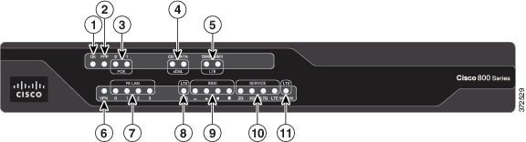
Table 1-35 describes the LEDs for Cisco C886VAG-LTE ISR.
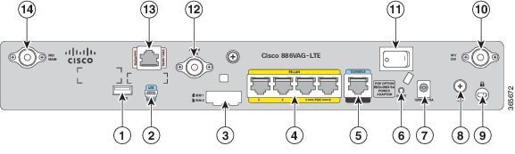
Figure 1-51 shows the back panel of the Cisco C886VAG-LTE ISR.
Figure 1-51 Back Panel of the Cisco C886VAG-LTE ISR
|
|
|
||
|
|
|||
|
|
|||
|
|
|||
|
|
|||
|
|
|
||
|
|
|
Cisco C887VAG-4G Integrated Services Router
Figure 1-52 shows the front panel of the Cisco C887VAG-4G ISR.
Figure 1-52 Front Panel of the Cisco C887VAG-4G ISR
Table 1-36 describes the LEDs for Cisco C887VAG-4G ISR.
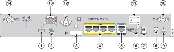
Figure 1-53 shows the back panel of the Cisco C887VAG-4G ISR.
Figure 1-53 Back Panel of the Cisco C887VAG-4G ISR
|
|
|
||
|
|
|||
|
|
|||
|
|
|||
|
|
|||
|
|
|
||
|
|
|
Cisco C896VAG-LTE Integrated Services Router
Figure 1-54 shows the front panel of the Cisco C896VAG-LTE ISR.
Figure 1-54 Front Panel of the Cisco C896VAG-LTE ISR
Table 1-37 describes the LEDs for Cisco C896VAG-LTE ISR.
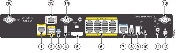
Figure 1-55 shows the back panel of the Cisco C896VAG-LTE ISR.
Figure 1-55 Back Panel of the Cisco C896VAG-LTE ISR
|
|
|
||
|
|
|
||
|
|
|
||
|
|
|
||
|
|
|
||
|
|
|
||
|
|
|
||
|
|
|
For information on installing Cisco C890 Series Routers, see the following link:
http://www.cisco.com/c/en/us/td/docs/routers/access/800/hardware/installation/guide/800HIG.html
Cisco C897VAG-LTE Integrated Service Router
Figure 1-56 shows the front panel of the Cisco C897VAG-LTE ISR.
Figure 1-56 Front Panel of the Cisco C897VAG-LTE ISR
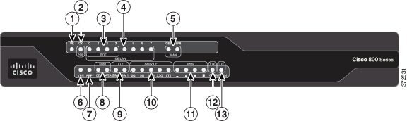
Table 1-38 describes the LEDs for the Cisco C897VAG-LTE ISR.
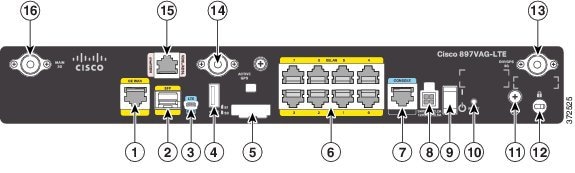
Figure 1-57 shows the back panel of the Cisco C897VAG-LTE ISR.
Figure 1-57 Back Panel of the Cisco C897VAG-LTE ISR
|
|
|
||
|
|
|
||
|
|
|
||
|
|
|
||
|
|
|
||
|
|
|
||
|
|
|
||
|
|
|
Cisco C898EAG-LTE Integrated Service Router
Figure 1-58 shows the front panel of the Cisco C898EAG-LTE ISR.
Figure 1-58 Front Panel of the Cisco C898EAG-LTE ISR

Table 1-39 describes the LEDs for the Cisco C898EAG-LTE ISR.
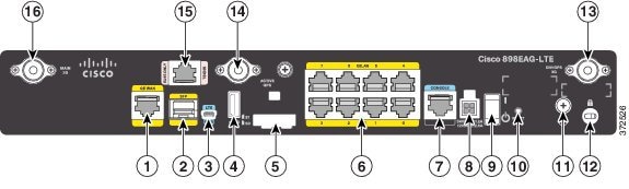
Figure 1-59 shows the back panel of the Cisco C898EAG-LTE ISR.
Figure 1-59 Back Panel of the Cisco C898EAG-LTE ISR
|
|
|
||
|
|
|
||
|
|
|
||
|
|
|
||
|
|
|
||
|
|
|
||
|
|
|
||
|
|
|
Cisco C899G-LTE Integrated Service Router
Figure 1-60 shows the front panel of the Cisco C899G-LTE ISR.
Figure 1-60 Front Panel of the Cisco C899G-LTE ISR
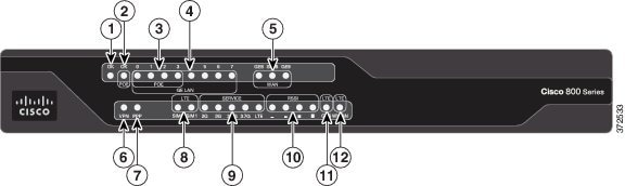
Table 1-40 describes the LEDs for the Cisco C899G-LTE ISR.
Figure 1-61 shows the back panel of the Cisco C899G-LTE ISR.
Figure 1-61 Back Panel of the Cisco C899G-LTE ISR
|
|
|
||
|
|
|
||
|
|
|
||
|
|
|
||
|
|
|
||
|
|
|
||
|
|
|
||
|
|
|
Cisco 890 Series Integrated Service Routers
Cisco 891, Cisco 892, and Cisco 892F
The Cisco 891, Cisco 892, and Cisco 892F ISRs have the following features:
- Integrated 8-port 10/100 Ethernet switch for connecting to the LAN
- 10/100 FE and 10/100/1000 Gigabit Ethernet (GE) port for connecting to the WAN
- Separate console and auxiliary ports
- (Optional) embedded Wi-Fi certified dual-radio 802.11a/b/g/n-compliant wireless AP
- Optional 4-port PoE
Note![]() The Cisco 890 Series ISRs can include an optional PoE module that provides power to 802.3af-compliant devices connected to Ethernet ports 0 through 3. If this feature was not configured with the factory order, you must order and install it to enable the PoE function.
The Cisco 890 Series ISRs can include an optional PoE module that provides power to 802.3af-compliant devices connected to Ethernet ports 0 through 3. If this feature was not configured with the factory order, you must order and install it to enable the PoE function.
Note![]() On a Cisco 891 series router, due to TCAM limitation, you can apply an ACL configuration on maximum 9 ports. If you apply the ACL configuration beyond 9 ports, the configuration will not be applied, and the router will display an error message.
On a Cisco 891 series router, due to TCAM limitation, you can apply an ACL configuration on maximum 9 ports. If you apply the ACL configuration beyond 9 ports, the configuration will not be applied, and the router will display an error message.
Note![]() Layer 2 FastEthernet ports of Cisco 800 series routers do not support Downloadable ACL(dACL). Layer 2 GigabitEthernet ports support downloadable ACL(dACL).
Layer 2 FastEthernet ports of Cisco 800 series routers do not support Downloadable ACL(dACL). Layer 2 GigabitEthernet ports support downloadable ACL(dACL).
- Security feature card (SFC) socket
- DIMM expansion socket that can accept up to 512 MB of additional memory, for a total of 768 MB system memory in Cisco 891 and Cisco 892 ISRs, and a total of 1 GB system memory in Cisco 892F series ISRs
- Three reverse-polarity Threaded Neill-Concelman (RP-TNC) connectors on the back panel for non-captive dual-band WLAN antenna (wireless models only)
- Support for the AIM2-CUE-K9 and AIM2-APPRE-104-K9
- GE small-form-factor pluggable (SFP) port (Cisco 892F series ISRs only)
The following feature is located on the front panel of
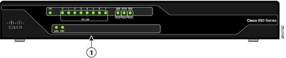
Figure 1-62 shows the front panel details of the Cisco 890 Series router.
Figure 1-62 Front Panel of the Cisco 890 Series ISR
|
|
|
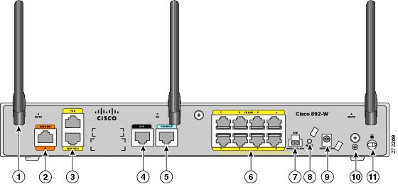
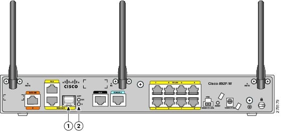
Figure 1-63 shows the back panel details of the Cisco 892W router. Non wireless routers do not have RP-TNC antennas or connectors on the back panel. Some of the features that are shown may not be available on your router. However, the feature locations are similar across all Cisco 890 series routers.
Figure 1-63 Back Panel of the Cisco 892W Router
|
|
Antenna—Dipole swivel antenna attached to RP-TNC connectors (wireless models only) |
|
PoE power connector for optional PoE module30 |
|
|
|
||
|
|
|
||
|
|
|
||
|
|
|
||
|
|
|
Figure 1-64 shows the location of the SFP port on a Cisco 892FW router.
Figure 1-64 SFP Port Location on a Cisco 892FW Router
|
|
|
Cisco 892FSP, Cisco 896VA, Cisco 897VA, and Cisco 898EA
The Cisco 892FSP, Cisco 896VA, Cisco897VA (includes Cisco 897VA, Cisco 897VAM, Cisco 897VAW, Cisco 897VAMW), and Cisco 898EA routers have the following features:
- Integrated 8-port 10/100/1000 Gigabit Ethernet switch for connecting to the LAN
- Two 10/100/1000 GE ports for Cisco 892FSP
- One 10/100/1000 GE port for Cisco 896VA, 897VA, and the Cisco 898EA. Either the SFP socket or the 10/100/1000 GE port can be active at a given time, but not both.
- Single console and auxiliary ports for configuration and management
- 512 MB of on-board memory (upgrade option to 1 GB)
- 256 MB flash memory for Cisco 896VA, Cisco 897VA, and Cisco 898EA
- One USB 2.0 port
- Optional internal adapter for inline PoE on four switch ports for IP phones or external wireless access points for Cisco 896VA, Cisco 897VA, and Cisco 898EA models only. No PoE support on Cisco 892FSP.
Note![]() The Cisco 892FSP does not support AIM2-CUE-K9 and AIM2-APPRE-104-K9 because it does not have an SFC socket.
The Cisco 892FSP does not support AIM2-CUE-K9 and AIM2-APPRE-104-K9 because it does not have an SFC socket.
Note![]() To upgrade DRAM memory from 512 MB to 1 GB on the Cisco 892FSP, Cisco 896VA, Cisco 897VA, and Cisco 898EA routers, you should enable the FL-8XX-512U1GB license.
To upgrade DRAM memory from 512 MB to 1 GB on the Cisco 892FSP, Cisco 896VA, Cisco 897VA, and Cisco 898EA routers, you should enable the FL-8XX-512U1GB license.
Figure 1-65 shows the back panel of the Cisco 892FSP Router.
Figure 1-65 Back Panel of the Cisco 892FSP Router
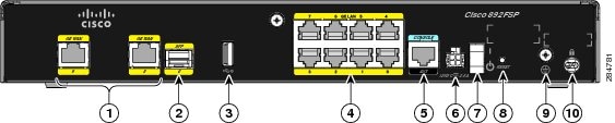
|
|
|
||
|
|
|
||
|
|
|
||
|
|
|
||
|
|
|
Figure 1-66 shows the front panel of the Cisco 892FSP Router.
Figure 1-66 Front Panel of the Cisco 892FSP Router
|
|
|||
Figure 1-67 shows the back panel of the Cisco 896VA Router.
Figure 1-67 Back Panel of the Cisco 896VA Router
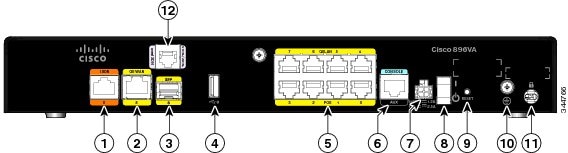
|
|
|
||
|
|
|
||
|
|
|
||
|
|
|
||
|
|
8-port Gigabit Ethernet switch33 |
|
|
|
|
|
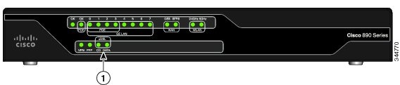
Figure 1-68 shows the front panel of the Cisco 896VA and the Cisco 897VA routers.
Figure 1-68 Front Panel of the Cisco 896VA and Cisco 897VA Routers
|
|
|||
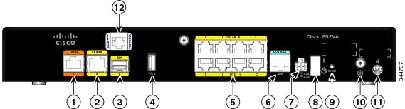
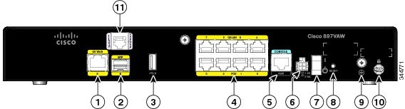
Figure 1-69 shows the back panel of the Cisco 897VA Router.
Figure 1-69 Back Panel of the Cisco 897VA Router
|
|
|
||
|
|
|
||
|
|
|
||
|
|
|
||
|
|
8-port Gigabit Ethernet switch34 |
|
|
|
|
|
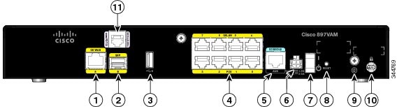
Figure 1-70 shows the back panel of the Cisco 897VAM Router.
Figure 1-70 Back Panel of the Cisco 897VAM Router
|
|
|
||
|
|
|
||
|
|
|
||
|
|
8-port Gigabit Ethernet switch35 |
|
|
|
|
|
||
|
|
|
Figure 1-71 shows the front panel of the Cisco 897VAM router.
Figure 1-71 Front Panel of the Cisco 897VAM Router
|
|
|||
Figure 1-72 shows the back panel of the Cisco 897VAW router.
Figure 1-72 Back Panel of the Cisco 897VAW Router
|
|
|
||
|
|
|
||
|
|
|
||
|
|
8-port Gigabit Ethernet switch36 |
|
|
|
|
|
||
|
|
|
Figure 1-73 shows the front panel of the Cisco 897VAW and the Cisco 897VAMW routers.
Figure 1-73 Front Panel of the Cisco 897VAW and the Cisco 897VAMW Routers
|
|
|||
Figure 1-74 shows the back panel of the Cisco 897VAMW Router.
Figure 1-74 Back Panel of the Cisco 897VAMW Router

|
|
|
||
|
|
|
||
|
|
|
||
|
|
8-port Gigabit Ethernet switch37 |
|
|
|
|
|
||
|
|
|
Figure 1-75 shows the back panel of the Cisco 898EA router.
Figure 1-75 Back Panel of the Cisco 898EA Router

|
|
|
||
|
|
|
||
|
|
|
||
|
|
8-port Gigabit Ethernet switch38 |
|
|
|
|
|
||
|
|
|

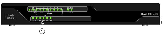
Figure 1-76 shows the front panel of the Cisco 898EA Router.
Figure 1-76 Front Panel of the Cisco 898EA Router
|
|
|||
Cisco C897VAB-K9
The Cisco 897VAB-K9 ISR is designed to support 2-pair VDSL2 bonding up to the 17a profile and single pair support for ADSL/VDSL over POTS up to the 30a profile.
Table 1-41 provides information about important hardware specifications pertaining to Cisco
|
|
|
|---|---|
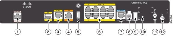
Figure 1-77 shows the back panel of the Cisco 897VAB-K9 ISR.
Figure 1-77 Back panel of the Cisco 897VAB-K9 ISR
|
|
Primary WAN VDSL / ADSL over POTS, VDSL2 Bonding39 |
|
|
|
|
|
||
|
|
|
||
|
|
|
||
|
|
|
||
|
|
8-port Gigabit Ethernet Switch40 |
|
|
39.1. ADSL and VDSL (up to 17a) single-pair functionality uses the center pair of pins in the RJ-11 connector. VDSL 30a single pair functionality makes use of the pins just adjacent to the center pins. VDSL Bonding makes use of both the center pair pins & those just adjacent to the center pair to provide the 2 bonded VDSL lines. For more information, see Cisco 890 Series Integrated Services Routers Data Sheet. 40.2. Ports 0 through 3 can be configured as POE, which is an optional feature for this model. If this feature is not configured with the factory order, you must order and install it to enable the PoE function. |
Figure 1-78 shows the front panel of the Cisco 897VAB-K9 ISR.
Figure 1-78 Front panel of the Cisco 897 VAB-K9 ISR
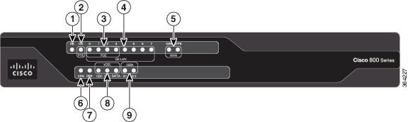
Table 1-42 describes the LEDs for the Cisco 897VAB-K9 ISR.
Cisco C891 Series ISRs
Cisco C891 Series ISRs are designed to deliver secure broadband, metro Ethernet, wireless LAN (WLAN) connectivity, and business continuity. Cisco C891 Series ISRs also provide a 1-port Gigabit Ethernet SFP socket for WAN connectivity.
This section includes the hardware information for the following models:
Table 1-43 provides information about the hardware specifications of the Cisco C891 Series Routers.
|
|
|
|---|---|
For detailed hardware specifications, see the Cisco C890 Series hardware data sheet at:
http://www.cisco.com/en/US/prod/collateral/routers/ps380/data_sheet_c78-519930.html
Cisco C891F Router
Figure 1-79 shows the front panel of the Cisco C891F Router.
Figure 1-79 Front Panel of the Cisco C891F Router
|
|
|
For detailed description about the LEDs on the Cisco C890 Series Routers, see the “LEDs” section.
Figure 1-80 shows the back panel of the Cisco C891F Router.
Figure 1-80 Back Panel of the Cisco C891F Router

|
|
|
||
|
|
|
||
|
|
|
||
|
|
|
||
|
|
|
||
|
|
|
||
|
|
|
For information on installing the Cisco C890 Series Routers, see:
http://www.cisco.com/en/US/docs/routers/access/800/860-880-890/hardware/installation/guide/2Install880-860.html
Cisco C891FW Router
Figure 1-81 shows the front panel of the Cisco C891FW Router.
Figure 1-81 Front Panel of the Cisco C891FW Router
|
|
|
For detailed description about the LEDs on Cisco C890 Series Router, see “LEDs” section.
Figure 1-82 shows the back panel of the Cisco C891FW Router.
Figure 1-82 Back Panel of the Cisco C891FW Router
|
|
|
||
|
|
|
||
|
|
|
||
|
|
|
||
|
|
|
||
|
|
|
||
|
|
|
For information on installing the Cisco C890 Series Routers, see:
http://www.cisco.com/en/US/docs/routers/access/800/860-880-890/hardware/installation/guide/2Install880-860.html
Cisco C891-24X/K9 Integrated Services Router
Cisco C891-24X/K9 Integrated Services Router (ISR) is a fixed Cisco 890 Series ISR that supports 24 port GE LAN. Cisco C891-24X/K9 ISR provides more switch port options compared to other 890 Series ISRs and Cisco C891-24X/K9 ISR is useful in deployment scenarios where more switching capability is required. Cisco C891-24X/K9 ISR also supports PoE on 8 switch ports. Cisco C891-24X/K9 ISR supports WAN connectivity through dual GE or SFP ports.
Table 1-44 provides information about important hardware specifications pertaining to Cisco C891-24X/K9 ISR.
|
|
|
|---|---|
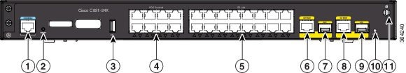
Figure 1-83 shows the front panel of the Cisco C891-24X/K9 ISR.
Figure 1-83 Front Panel of the Cisco C891-24X/K9 ISR
Figure 1-84 shows the back panel of the Cisco C891-24X/K9 ISR.
Figure 1-84 Back Panel of the Cisco C891-24X/K9 ISR
|
|
|
||
|
|
|
||
|
|
|
||
|
|
|
||
|
|
|
||
|
|
|
For information on installing the C891-24X/K9 ISR see the following link:
http://www.cisco.com/c/en/us/td/docs/routers/access/800/hardware/installation/guide/800HIG/installing.html
Hardware Features
This section provides an overview of the following hardware features for the Cisco 860 Series, 880 Series, and 890 Series ISRs. A feature summary is available at the end of this section.
Kensington Lock
A Kensington security slot is located on the router back panel. To secure the router to a desktop or other surface, use the Kensington lockdown equipment.
Reset Button
The Reset button is used to restore the router to the factory default configuration or to load a custom configuration file.
There are two different ways to do this:
- By pressing the Reset button within 5 seconds of powering up the router.
- By pressing the Reset button for 5 seconds while running IOS software.
Note![]() If you execute a CLI reboot command while the embedded wireless AP is running Cisco Unified Wireless Network software, the router reboots, but the AP continues to run. Clients with Cisco Unified Wireless Network software are controlled by a wireless LAN controller (WLC) and can be reset only by the controller.
If you execute a CLI reboot command while the embedded wireless AP is running Cisco Unified Wireless Network software, the router reboots, but the AP continues to run. Clients with Cisco Unified Wireless Network software are controlled by a wireless LAN controller (WLC) and can be reset only by the controller.
Cisco 860VAE Routers—Custom Configuration File
On the Cisco 860VAE routers, the reset button can be used to load a custom configuration file without having to use the CLI. The configuration file can be located on an external USB flash drive or on the router's compact flash.
The custom configuration file must be named one of the following:
When the system attempts to load a custom configuration file, configuration files on a USB flash drive have priority over configuration files on the router's flash drive and the SN-customer-config file name has priority over the customer-config file name. The priority for loading a configuration file is as follows:
1.![]() USB flash0—SN-customer-config
USB flash0—SN-customer-config
3.![]() Router flash—SN-customer-config
Router flash—SN-customer-config
4.![]() Router flash—customer-config
Router flash—customer-config
If the router does not find a valid custom configuration file, the system aborts the process.
To reset the router to the factory default configuration, follow these steps:
Step 1![]() Verify that Cisco IOS is running correctly by checking that the system status LED is on.
Verify that Cisco IOS is running correctly by checking that the system status LED is on.
Step 2![]() Press and hold the Reset button until the system status LED begins to flash. Typically, this occurs within 5 seconds.
Press and hold the Reset button until the system status LED begins to flash. Typically, this occurs within 5 seconds.
The router reloads itself after the startup configuration has been replaced with the new customer configuration.
Custom Configuration File for Cisco 892FSP, Cisco 896VA, Cisco 897VA, and Cisco 898EA
In the first method, the configuration file can be located on the router's compact flash or on the router's NVRAM. The custom configuration file must use cfg as the filename extension.
When the system attempts to load a custom configuration file, configuration files on NVRAM have priority over configuration files on the router's compact flash.
The priority for loading a configuration file is as follows:
If the router does not find a valid custom configuration file, the system aborts the process.To reset the router to the factory default configuration or to load a custom configuration file, follow these steps:
Step 2![]() Press and hold the Reset button until the system status LED begins to flash. Typically, this occurs within 5 seconds.
Press and hold the Reset button until the system status LED begins to flash. Typically, this occurs within 5 seconds.
The router reloads itself after the startup configuration has been replaced with the new customer configuration.
In the second method, the configuration file can be located on an external USB flash drive or on the router's compact flash.
The custom configuration file must be named one of the following:
When the system attempts to load a custom configuration file, configuration files on a USB flash drive have priority over configuration files on the router's flash drive and the "customer-config.SN" file name has priority over the customer-config file name.
The priority for loading a configuration file is as follows:
1.![]() usbflash0:customer-config.SN
usbflash0:customer-config.SN
3.![]() Router flash:customer-config.SN
Router flash:customer-config.SN
4.![]() Router flash:customer-config
Router flash:customer-config
If the router does not find a valid custom configuration file, the system aborts the process.
To reset the router to the factory default configuration or to load a custom configuration file, follow these steps:
Step 1![]() Verify that Cisco IOS is running correctly by checking that the system status LED is on.
Verify that Cisco IOS is running correctly by checking that the system status LED is on.
Step 2![]() Press and hold the Reset button until the system status LED begins to flash. Typically, this occurs within 5 seconds.
Press and hold the Reset button until the system status LED begins to flash. Typically, this occurs within 5 seconds.
The router reloads itself after the startup configuration has been replaced with the new customer configuration.
LEDs
The LEDs are located on the front panel of the router.
- Table 1-45 describes the LEDs for the Cisco 860 Series, Cisco 880 Series, and Cisco 890 Series ISRs.
- Table 1-46 lists the LED descriptions for the Cisco 866VAE, Cisco 867VAE, Cisco 866VAE-K9, and Cisco 867VAE-K9 ISRs.
- Table 1-47 lists the LED description for the Cisco 892FSP, Cisco 896VA, Cisco 897VA, and Cisco 898EA ISRs.
- For a description of LEDs for Cisco 860VAE-W-A-K9, Cisco 860VAE-W-E-K9, and Cisco 860VAE-POE-W-A-K9 ISRs models, see the “Cisco 860VAE-W-A-K9, Cisco 860VAE-W-E-K9, and Cisco 860VAE-POE-W-A-K9 ISRs” section.
|
|
|
|
|
|
|
|---|---|---|---|---|---|
On—DC power is being supplied to the router and the Cisco IOS software is running. Blinking—Bootup is in process, or the router is in Rommon monitor mode. |
|||||
| On—Ethernet port is connected. Blinking—Data is either being received or being transmitted. |
|||||
| On—Ethernet port is connected. Blinking—Data is either being received or being transmitted. |
|||||
| Blinking—Data is either being received or being transmitted. |
|||||
| Blinking—Data is either being received or being transmitted. |
|||||
On—Radio is connected, SSID41 is configured, and client is associated, but no data is being received or being transmitted. Slow blinking—Radio is connected, SSID is configured, and beacons are being transmitted. Fast blinking—Data is either being received or being transmitted. |
|||||
On—Radio is connected, SSID is configured, and client is associated, but no data is being received or being transmitted. Slow blinking—Radio is connected, SSID is configured, and beacons are being transmitted. Fast blinking—Data is either being received or being transmitted. |
|||||
| Blinking—Ethernet link is up, and data is either being received or being transmitted. |
|||||
On—Ethernet link is up, and wireless access point (AP) is communicating with LWAPP42 controller. Blinking—Ethernet link is up, but wireless AP is not communicating with LWAPP controller. |
|||||
PPP43 |
|||||
xDSL44 CD |
On—The xDSL interface is connected to the DSLAM45. Blinking—Training to the line. Off—Indicates that a connection has not been established or the port is shut down. |
||||
Blinking—The xDSL interface is either receiving or transmitting data. |
|||||
On—The router is operating in ATM46 mode. |
|||||
Blink—The router is operating in EFM47 mode. |
|||||
Blinking—B1 channel is either receiving or sending data, or data is passing through ISDN channel 1. |
|||||
Blinking—B2 channel is receiving or sending data, or data is passing through ISDN channel 2. |
|||||
| Slow Blinking—Searching for service. Fast Blinking—Data is either being received or being transmitted. |
|||||
| 3G RSSI50 |
Off—Low signal strength (lower than -100 dBm). On—High RSSI (-69 dBm or higher). |
||||
3G GSM51 |
|||||
3G CDMA52 |
|||||
88153 |
|||||
On—BRI B1 channel is connected. Blinking—BRI B1 channel is either receiving or transmitting data. |
|||||
On—BRI B2 channel is connected. Blinking—BRI B2 channel is either receiving or transmitting data. |
|||||
| Blinking—FXS/DID port is either receiving or transmitting data. |
|||||
| Blinking—V.92 port is either receiving or transmitting data. |
|||||
| SFP54 EN |
|||||
|
44.xDSL = General term referring to various forms of DSL, including ADSL (asymmetric digital subscriber line) and VDSL (very-high-data-rate digital subscriber line). |
Table 1-46 describes the LEDs for the Cisco 866VAE, Cisco 867VAE, Cisco 866VAE-K9, and Cisco 867VAE-K9 ISRs.
|
|
|
|
|---|---|---|
Power is on and system running in the ROMMON mode. Note During the early booting stage, both Power/System, GE_MODE, and DSL_LINK LED will be turned on temporarily for the power on test. DSL_LINK and GE_MODE LED will be turned off later after booting into ROMMON. |
||
Power/System LED: Solid |
||
Power/System LED: Solid |
Cisco IOS functioning in DSL_WAN mode. Note In Cisco IOS DSL_WAN mode, DSL_LINK LED will be solid after DSL training complete or flashing during training. |
|
xDSL55 ACT |
Blinking—DSL WAN activity (traffic in either direction). |
|
| On—DSL WAN Mode is selected and DSL training complete. Blinking—DSL WAN Mode is selected but incomplete DSL Link Up state, such as in-training, or controller “OFF,” or no cable attached to DSL connector. |
||
|
55.xDSL = General term referring to various forms of DSL, includi\\\\\\\\\\\\\\\\\\\\\\\\\\\\\\\\\ ng ADSL (asymmetric digital subscriber line) and VDSL (very-high-data-rate digital subscriber line). |
Table 1-47 describes the LEDs for the Cisco 892FSP.
Table 1-47 LED desciption for Cisco 892FSP ISR, 896VA, 897VA, and 898EA Routers
Shared LEDs on the Cisco 881-V and Cisco 887VA-V Voice and Data Routers
On the Cisco 881-V, Cisco 887VA-V, and Cisco 887VA-V-W routers, the BRI1, BRI2 and the FXS ports share LED indicators. The following ports share an LED indicator:
- BRI 1B1 channel and FXS 3
- BRI 1B2 channel and FSX 4
- BRI 2B1 channel and FXS 5
- BRI 2 B2 channel and FXS 6
Because the LED indicators are shared, the LED illuminates (green) when either port is active. For example, the LED indicator labeled BRI 1 B1 illuminates when either the BRI1 B1 channel is active or when the FXS port is active. You can determine the activity status on each interface by using the following commands.
- For activity status on the FXS ports, use the show port summary command.
- For activity status on the BRI ISDN port, use the s how isdn status command.
Figure 1-85 shows a close-up view of the LED indicators.
Figure 1-85 Close-up of the BRI and FXS LED Indicators
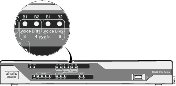
Memory
The Cisco 860 series, 880 series, and 890 series routers contain flash memory and main memory.
Flash Memory
The Cisco 860 series, 880 series, and 890 series ISRs use non-upgradable flash memory storage. The onboard flash memory contains the Cisco IOS software image, the boot flash contains the ROMMON boot code, and a separate non-volatile flash contains the cookie configuration.
Table 1-48 describes the default flash memory storage.
|
|
|
|---|---|
Note![]() Flash memory is not upgradable. An external USB flash memory module may be used if additional flash memory is needed.
Flash memory is not upgradable. An external USB flash memory module may be used if additional flash memory is needed.
Main Memory
Table 1-49 describes the main onboard memory storage for different router models.
|
|
|
|
|---|---|---|
A memory expansion slot accommodates a PC2-4200, 256-MB or 512-MB double data rate 2 (DDR2) SODIMM, for a maximum of 768 MB. |
||
USB Port
Table 1-50 describes the USB ports for different router models.
|
|
|
|---|---|
One USB 1.1-compliant port located on the back panel. The USB port does not support eToken. |
|
Cisco 860VAE-W-A-K9, Cisco 860VAE-W-E-K9, and Cisco 860VAE-POE-W-A-K9 series |
For moe information, refer to the “Cisco 860VAE-W-A-K9, Cisco 860VAE-W-E-K9, and Cisco 860VAE-POE-W-A-K9 ISRs” section. |
One USB 1.1-compliant port located on the front panel. The USB port provides connection for USB devices such as security tokens and flash memory. |
|
Cisco 890 series56 |
|
|
56.Except for Cisco 892FSP, Cisco 896VA, Cisco 897VA, and Cisco 898EA. |
Fan
Some router models do not have a fan, while other models have either one or two fans.
The fans spin at full speed, as a diagnostic aid, immediately after the router is powered up. After the router has booted, the fans spin as fast as necessary to minimize fan noise while maintaining a safe internal operating temperature.
Power Supply
The Cisco 892FSP has a single +12V power supply input. The Cisco 892FSP power connector is different from the barrel-type connector on other 890 series models. The AC adapter cable connector has four pins and a built-in locking mechanism. Figure 3-33 shows the power adapter connector.
The Cisco 896VA, 897VA, and Cisco 898EA use PoE (12 VDC 43 W, -54 VDC 80 W) and non-PoE (12 VDC 60 W) power supplies.
Power over Ethernet Module
The Cisco 880 series ISRs can include an optional Power over Ethernet (PoE) module that provides power to 802.3af-compliant devices connected to FE ports 0 and 1.
The Cisco 890 series ISRs can include an optional PoE module that provides power to 802.3af-compliant devices connected to FE ports 0, 1, 2, and 3.
The PoE module is an option available only for the Cisco 880 series and 890 series ISRs and requires a 48 V external power adapter.
This function can be added to an 880 or 890 series router by installing the PoE adapter card in the router and inserting the PoE 48 V external power adapter.
Note![]() The Cisco 880 series ISRs with embedded WLAN antennas require a single external power supply: a 30 W power supply for non-POE-enabled routers or a 60 W power supply for POE-enabled routers. For the back panels of some of these routers, see Figure 1-33 and Figure 1-35.
The Cisco 880 series ISRs with embedded WLAN antennas require a single external power supply: a 30 W power supply for non-POE-enabled routers or a 60 W power supply for POE-enabled routers. For the back panels of some of these routers, see Figure 1-33 and Figure 1-35.
3G Cellular Data WAN Connectivity
The 3G (Evolution Data Only [EVDO], Universal Mobile Telecommunications Systems [UMTS]) cellular interface is intended for use as a backup data link, but it can also be used as a primary WAN data link. The 3G technology is third-generation wide-area cellular technology that is used in voice telephony and broadband wireless data in a mobile environment.
Some Cisco 880G models come with a 34-mm express card slot ready for use with a commercial 3G card radio. The 3G express card slot is located on the front panel. For a list of supported 3G cards, see the Cisco 880 Series Integrated Services Routers Data Sheet.
Other Cisco 880G models come with embedded WAN modems for use over GSM or CDMA networks. These routers have antenna connectors on the back panel. GSM routers have two SIM card slots. For information on configuring Cisco 880 series ISRs for 3G, see Configuring Cisco EHWIC and 880G for 3G (EV-DO Rev A) and Configuring Cisco EHWIC and 880G for 3.7G (HSPA+)/3.5G (HSPA).
Wireless LAN Connectivity
The embedded Wi-Fi CERTIFIED™, 802.11a/b/g/n-compliant wireless AP is preinstalled in the router as an optional feature. The Cisco 860 series routers support autonomous features and network configurations. The Cisco 880 series and 890 series routers support both autonomous and unified features and network configurations.
The wireless AP does not have an external Console port. Use the router’s Console port as described in Chapter3, “Connecting the Router” To configure the wireless device, use the Cisco IOS command-line interface (CLI).
Table 1-51 describes the radios and antennas for the Cisco 860 series, 880 series, and 890 series routers.
Note![]() Cisco 860VAE ISRs do not support wireless LAN connectivity.
Cisco 860VAE ISRs do not support wireless LAN connectivity.
The 5-GHz radio operates in the Unlicensed National Information Infrastructure (UNII) 1, 2, 3, 5-GHz frequency bands.
|
|
|
|
|
|
|
|---|---|---|---|---|---|
Cisco 860 and 880 series routers Note Cisco 860VAE ISRs do not support wireless LAN connectivity. |
Three captive, omnidirectional dipole antennas: 2 dBi at |
||||
Three embedded, dual-band, omnidirectional antennas: 2 dBi at |
|||||
Dual-band simultaneous 802.11a/n and 802.11b/g/n |
Three dual-band, removable, 2.4-GHz/5-GHz omnidirectional dipole RP-TNC antenna58 |
|
57.Actual data rate is highly dependent on your wireless environment. 58.The antennas require some minor installation. They must be screwed onto the RP-TNC antenna connectors on the I/O side of the chassis. See the following document on Cisco.com for feature information: http://www.cisco.com/en/US/docs/routers/access/wireless/hardware/notes/antdip.html |
Supported Cisco Radio Antennas
The Cisco 891, Cisco 892, and Cisco 892F come with three removable dipole antennas that can be replaced using the Cisco approved antenna extenders listed in Table 1-52 .
Note![]() Cisco supports only the antennas listed in Table 1-52 with the Cisco 890 series dual-band radio module.
Cisco supports only the antennas listed in Table 1-52 with the Cisco 890 series dual-band radio module.
|
|
|
|
|
|---|---|---|---|
This is the default antenna. It is a swivel-mount dipole dual-band blade antenna. For more information, see Cisco Multiband Swivel-Mount Dipole Antenna (AIR-ANTM2050D-R). |
|||
Ceiling-mount dual-band antenna. This antenna has a clip that allows it to be mounted on a drop-ceiling cross member. For more information, see Cisco Multiband Diversity Omnidirectional Ceiling-Mount Antenna. |
|||
Wall-mount dual-band antenna. For more information, see Cisco Multiband Wall-Mount, Corner-Mount, or Mast-Mount Antenna. |
Small Form-Factor Pluggable Port
The SFP port supports auto-media-detection, auto-failover, and remote fault indication (RFI), as described in the IEEE 802.3ah specification.
Feature Summary
Table 1-53 summarizes the hardware features available in the Cisco 860 series, Cisco 880 series, and Cisco 890 series ISRs.
|
|
|
|
|
|
|---|---|---|---|---|
FE59 built-in switch ports |
Provides connection to 10/100BASE-T (10/100-Mb/s) Fast Ethernet networks. The autosensing function in these routers eliminates the need for a crossover cable and enables the router to detect MDI60 or MDIX61 in any other PC or hub with a straight-through cable or a crossover cable. |
|||
GE62 built-in switch port |
Provides connection to 10/100/1000BASE-T (10/100/1000-Mb/s) Gigabit Ethernet networks. The autosensing function in these routers eliminates the need for a crossover cable and enables the router to detect MDI63 or MDIX64 in any other PC or hub with a straight-through cable or a crossover cable. |
892FSP, 896VA, 897VA, 897VAB, 897VAM, 897VAW, 897VAMW, 898EA |
||
Provides a connection to the terminal or PC for software configuration or troubleshooting. The Console port may be configured as a virtual auxiliary port for dial backup and remote management. Cisco 891, Cisco 892, and Cisco 892F have separate console and auxiliary ports. |
||||
Provides support for VPNs65, Cisco IOS Firewall, and IPSec66. The Cisco 880 series routers also provide URL filtering. |
||||
Provides Wi-Fi CERTIFIED™ 802.11a/b/g/n compliance. |
||||
Provides connection to 10/100BASE-T. Can be connected to other network devices, such as a cable modem, an xDSL69 modem, or router. The router is capable of bridging and multiprotocol routing between the LAN and WAN ports. |
||||
VDSLoPOTS70 port |
||||
Provides ADSL connection over basic telephone service with Annex A and Annex B ITU G. 992.1 (ADSL), G.992.3 (ADSL2), and G.992.5 (ADSL). |
||||
Provides ADSL2/2+ or VDSL connection over POTS or ISDN (ISDN on 886VA only). |
892FSP, 896VA, 897VA, 897VAB, 897VAM, 897VAW, 897VAMW, 898EA |
|||
RTC provides nonvolatile date and time when the router is powered on. The RTC is used for verifying the validity of the Certification Authority stored on the router. It is backed up by a nonreplaceable lithium battery. |
||||
Supports USB 1.1. Provides connection for USB devices such as security tokens and flash memory. The Cisco 880 series routers have a single USB port; the Cisco 890 series routers have two USB ports. Cisco 880 series routers with embedded WLAN antennas have one USB 2.0 port. Cisco 892FSP and Cisco 860VAE series routers have one USB 2.0 port on the rear panel for temporary installation of a Cisco-approved USB memory device for maintenance purposes only. The port supports only USB 2.0. Refer to the product datasheet for the list of supported USB flash memory devices. Note Cisco 860VAE series router USB port does not support eToken. |
||||
PoE71 |
(Optional) Provides power for 802.3af-compliant devices (such as phones) that are connected to the router. The Cisco 880 series routers support a 2-port PoE module; the Cisco 890 series routers support a 4-port PoE module. |
|||
G.SHDSL72 port |
||||
3G73 card slot |
||||
Detects when the router is losing power, and sends a power-fail signal to warn the DSLAM74 about the impending line drop. |
892FSP, 896VA, 897VA, 897VAB, 897VAM, 897VAW, 897VAMW, 898EA |
|||
Provides backup and remote management functions by connecting to the ISDN service provider if the main VDSL or G.SHDSL link fails. |
xDSL models, except for the 3G and SRST75 models |
|||
Provides dial backup and remote management functions if the main WAN link fails. |
||||
FXO76 port |
An FXO interface connects local calls to a central office or PBX. This is the interface a standard telephone provides. |
|||
An FXS interface connects directly to a standard telephone, fax machine, or similar device. This interface supplies ringing voltage and dial tone to the station. |
||||
The ISDN BRI S/T voice interface provides a client-side (TE) ISDN S/T physical interface for connection to an NT1 device that terminates an ISDN telephone network. |
||||
SFP79 port |
Supports auto-media-detection, auto-failover, and remote fault indication (RFI), as described in the IEEE 802.3ah specification. |
892F models, 892FSP, 896VA, 897VA, 897VAB, 897VAM, 897VAW, 897VAMW, 898EA |
 Feedback