Installing the Router
This chapter describes the equipment and the procedures for successfully installing the Cisco 860, 880, 890 ISRs, Cisco 819 ISRs, and the Cisco 812 ISRs, and contains the following sections:
Installing the Cisco 810 ISR
This section contains the following:
Installing the Cisco 812 ISR
This section describes the equipment and the procedures for successfully installing Cisco 812 ISR and contains the following sections:
- Items Shipped with your Router
- Items Shipped with your PoE+ Splitter
- Installing the Cisco PoE+ Splitter
- Installing the SIM Card
- Installing the 3G Antenna
- Mounting the Cisco 812 ISR

Warning![]() Installation of the equipment must comply with local and national electrical codes. Statement 1074
Installation of the equipment must comply with local and national electrical codes. Statement 1074
Warning![]() Voltages that present a shock hazard may exist on Power over Ethernet (PoE) circuits if interconnections are made using uninsulated exposed metal contacts, conductors, or terminals. Avoid using such interconnection methods, unless the exposed metal parts are located within a restricted access location and users and service people who are authorized within the restricted access location are made aware of the hazard. A restricted access area can be accessed only through the use of a special tool, lock and key or other means of security. Statement 1072
Voltages that present a shock hazard may exist on Power over Ethernet (PoE) circuits if interconnections are made using uninsulated exposed metal contacts, conductors, or terminals. Avoid using such interconnection methods, unless the exposed metal parts are located within a restricted access location and users and service people who are authorized within the restricted access location are made aware of the hazard. A restricted access area can be accessed only through the use of a special tool, lock and key or other means of security. Statement 1072
Items Shipped with your Router
Unpack the box and verify that all items listed on the invoice were shipped with the Cisco 812 ISR.
The following items are shipped with your router:
Items Shipped with your PoE+ Splitter
Unpack the box and verify that all items listed on the invoice were shipped with the Cisco PoE+ splitter (C810-POE-SPL).
The following items are shipped with your PoE+ splitter:

Note![]() The above items are acceptable for use in Plenums and Air-handling spaces.
The above items are acceptable for use in Plenums and Air-handling spaces.
Installing the Cisco PoE+ Splitter
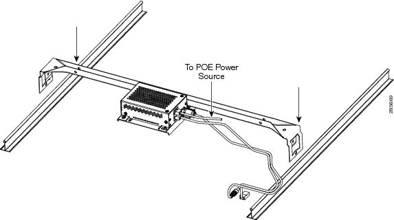
The PoE+ splitter (C810-POE-SPL) is an optional accessory that is intended to be mounted to the ceiling tile rails (24 inches span) using the only supported box hanger available from a Cooper B-line BA50 distributor. The screws, cables, and power cord lock needed for the installation are included in the PoE+ splitter accessory kit. A 5 VDC power cable with 1.3 meters in length connects the 5 VDC output of the PoE+ splitter to the router power input.
To install the Cisco PoE+ splitter, perform these steps:
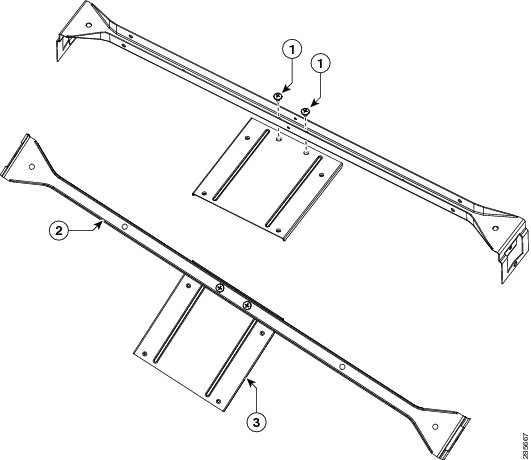
Step 1![]() Secure the PoE+ splitter mounting plate into the rail from the BA50 with two 10-24 screws (see Figure 2-1).
Secure the PoE+ splitter mounting plate into the rail from the BA50 with two 10-24 screws (see Figure 2-1).
|
|
|
|
|
|
|
|
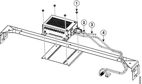
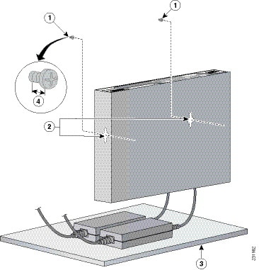
Step 2![]() Install the PoE+ splitter into the mounting plate with four 6-32 screws. (See Figure 2-2.)
Install the PoE+ splitter into the mounting plate with four 6-32 screws. (See Figure 2-2.)
|
|
|
||
|
|
|
Step 3![]() Connect the supplied plenum rated Cat5 cable to the GE0 port on the PoE+ splitter.
Connect the supplied plenum rated Cat5 cable to the GE0 port on the PoE+ splitter.
Step 4![]() Connect the Cat5 cable from your PoE+ source to the PoE+ in port on the PoE+ splitter.
Connect the Cat5 cable from your PoE+ source to the PoE+ in port on the PoE+ splitter.
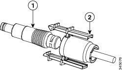
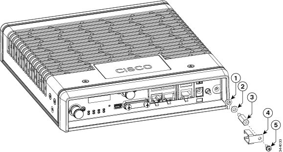
Step 5![]() Place the power cord lock onto the power cord behind the connector overmold as shown in Figure 2-3. Slide the power cord lock forward so that it captures the overmold and is fully seated.
Place the power cord lock onto the power cord behind the connector overmold as shown in Figure 2-3. Slide the power cord lock forward so that it captures the overmold and is fully seated.
Figure 2-3 Placement of the Power Cord Lock onto the Power Cord
|
|
|
|
|
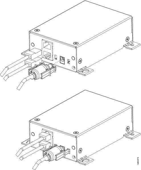
Step 6![]() Install the power cord with power cord lock to the power jack of the PoE+ splitter while making sure that the two arms of the power cord lock slide into the corresponding slots on the PoE+ splitter and are fully seated with both arms locking into the slots. Figure 2-4 shows the installation of the power cord lock and other cables.
Install the power cord with power cord lock to the power jack of the PoE+ splitter while making sure that the two arms of the power cord lock slide into the corresponding slots on the PoE+ splitter and are fully seated with both arms locking into the slots. Figure 2-4 shows the installation of the power cord lock and other cables.
In the event that the power cord lock needs to be removed, user your thumb and index fingers to squeeze the ends of the tabs while pulling away from the PoE+ splitter.
Figure 2-4 Installation of the Power Cord Lock and Other Cables
Step 7![]() Remove one ceiling tile to gain access.
Remove one ceiling tile to gain access.
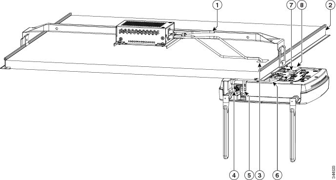
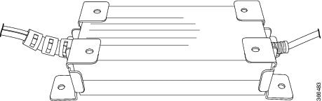
Step 8![]() Install the pre-assembled rail with PoE+ splitter into the T-rail. Push down the box hanger mounting clips to lock into the T-rail as shown in Figure 2-5.
Install the pre-assembled rail with PoE+ splitter into the T-rail. Push down the box hanger mounting clips to lock into the T-rail as shown in Figure 2-5.
Installing the SIM Card
This section describes how to install and replace the SIM card. Ensure that the router is not mounted to a wall, rack, or DIN rail.

Warning![]() Hot surface. Statement 1079
Hot surface. Statement 1079
To install the SIM card, perform these steps:
Step 1![]() Power off the router and disconnect the power cable from the power source.
Power off the router and disconnect the power cable from the power source.
Step 2![]() Place the router on a sturdy solid surface and orient the SIM access panel up to gain access. Ensure that any installed antennas are oriented appropriately to avoid damage.
Place the router on a sturdy solid surface and orient the SIM access panel up to gain access. Ensure that any installed antennas are oriented appropriately to avoid damage.
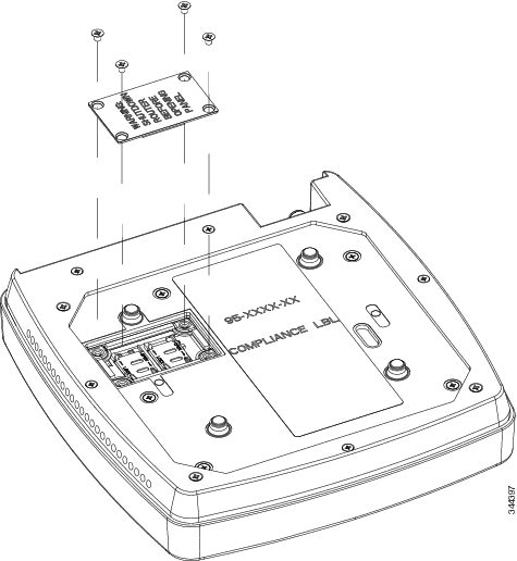
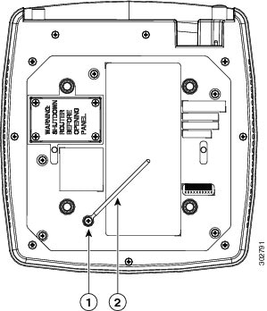
Step 3![]() Remove the SIM access panel being held in place by four 6-32 screws. (See Figure 2-6).
Remove the SIM access panel being held in place by four 6-32 screws. (See Figure 2-6).
Figure 2-6 Accessing the SIM Card
Step 4![]() Remove the SIM card and install the new cards.
Remove the SIM card and install the new cards.
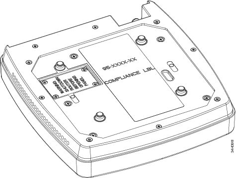
Step 5![]() Reinstall the same 6-32 flat head screws using a screw driver to secure the access panel back in place. Figure 2-7 shows the SIM card installed and the SIM access panel closed.
Reinstall the same 6-32 flat head screws using a screw driver to secure the access panel back in place. Figure 2-7 shows the SIM card installed and the SIM access panel closed.
Installing the 3G Antenna
Note![]() Install the antenna before you mount the Cisco 812 ISR.
Install the antenna before you mount the Cisco 812 ISR.
Warning![]() Do not locate the antenna near overhead power lines or other electric light or power circuits, or where it can come into contact with such circuits. When installing the antenna, take extreme care not to come into contact with such circuits, because they may cause serious injury or death. For proper installation and grounding of the antenna, please refer to national and local codes (for example, U.S.:NFPA 70, National Electrical Code, Article 810, Canada: Canadian Electrical Code, Section 54). Statement 1052
Do not locate the antenna near overhead power lines or other electric light or power circuits, or where it can come into contact with such circuits. When installing the antenna, take extreme care not to come into contact with such circuits, because they may cause serious injury or death. For proper installation and grounding of the antenna, please refer to national and local codes (for example, U.S.:NFPA 70, National Electrical Code, Article 810, Canada: Canadian Electrical Code, Section 54). Statement 1052
To install the 3G antennas to the router, perform these steps:
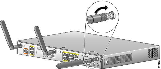
Step 1![]() Manually screw the antenna tight to the TNC connectors on the far left corner of the front panel.
Manually screw the antenna tight to the TNC connectors on the far left corner of the front panel.
Note![]() It may be easier to straighten out the antenna before attaching it to the TNC connector and then bend it back to the desired orientation once it is tight.
It may be easier to straighten out the antenna before attaching it to the TNC connector and then bend it back to the desired orientation once it is tight.
Figure 2-8 Installing the 3G Antenna
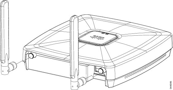
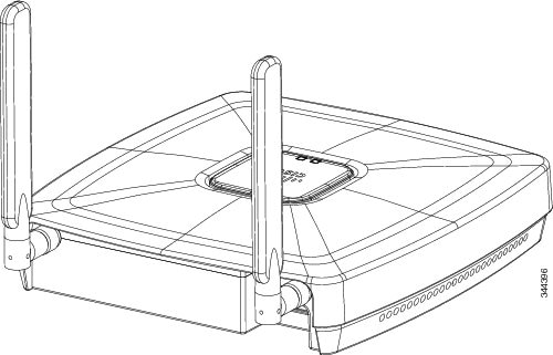
Step 2![]() Orient the antenna perpendicular with respect to the floor. Figure 2-9 shows the 3G antenna installed.
Orient the antenna perpendicular with respect to the floor. Figure 2-9 shows the 3G antenna installed.
Figure 2-9 3G Antenna Installed
Mounting the Cisco 812 ISR
This section describes the steps in mounting the Cisco 812 ISR in several configurations, including on a suspended ceiling, on a hard ceiling or wall, and on an electrical or network box. This section contains the following topics:
Mounting Hardware
Mounting hardware for the Cisco 812 ISR consists of brackets, which connect to the bottom of the router, and ceiling grid clips, which connect the bracket to a suspended ceiling. The bracket that you need depends on the mounting location for the router. The ceiling grid clip that you need depends on the type of suspended ceiling where you need to install the router. You do not need ceiling grid clips if you are mounting the router to a hard-surface ceiling or a wall.
Mounting Bracket
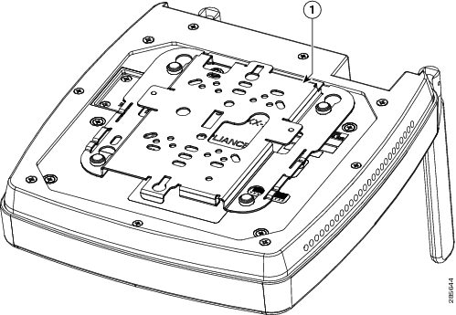
The Cisco 812 ISR has only one mounting bracket. The C810-BR-CM universal bracket is versatile. It works with electrical boxes, can be used for wall mounting, and adapts to ceiling installations. Figure 2-10 shows the universal bracket installed on the Cisco 812 ISR.
Figure 2-10 Universal Bracket Installed on the Cisco 812 ISR
|
|
Ceiling Grip Clips
Use a ceiling grid clip to mount the router on a suspended ceiling. The ceiling grid clip that you need depends on the ceiling tiles on your ceiling. There are two types of ceiling grid clips:
- Ceiling Grid Clip, Recessed (AIR-AP-T-RAIL-R)—If your ceiling tiles hang below the ceiling grid, this clip provides the best fit between the router and the ceiling.
- Ceiling Grid Clip, Flush (AIR-AP-T-RAIL-F)—If your ceiling tiles are flush with the ceiling grid, this clip provides a snug fit between the router and the ceiling.
The standard 9/16, 15/16, and 1 ½-inch wide T-rail mounting are supported with the Ceiling Grip Clips.
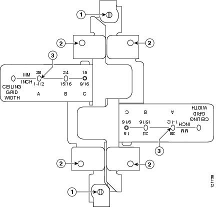
Figure 2-11 shows a ceiling grid clip.
Additional Adapters for Channel and Beam Ceiling Rails
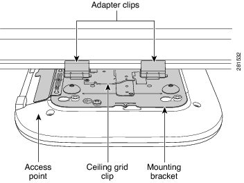
The most common type of suspended ceiling support rail (the support for the ceiling tiles) is the ceiling Tile rail or T-rail for short. You can attach a ceiling grid clip directly to a T-rail ceiling rail. However, other types of ceiling rails, such as channel rails and beam rails, require an additional adapter clip (AIR-CHNL-ADAPTER). You need two adapter clips for each router. Set screws on the clips hold them securely on the ceiling rail.
Figure 2-12 shows the three types of ceiling rails: T-rail, channel, and beam. Figure 2-13 shows the Cisco Access Point installed with mounting bracket, ceiling grid clip, and adapter clips.
Figure 2-12 T-Rail, Channel, and Beam Ceiling Rail Types
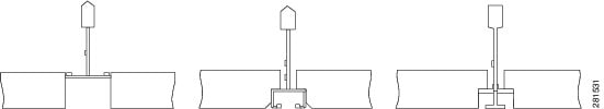
Figure 2-13 Adapter Clips Installed with Ceiling Grid Clips
Mounting the Cisco 812 ISR Below a Suspended Ceiling
The recommended power option for the Cisco 812 ISR, when mounted below a suspended ceiling, is the Cisco C810-POE-SPL (PoE+ splitter) with the use of the supplied 1.3 meter power cable and Cat5 cable (Plenum rated). The cables can be hidden above the suspended ceiling for a clean installation. See the “Installing the Cisco PoE+ Splitter” section for details on installing the PoE+ splitter.
Use a flat screwdriver if there is a need to remove the GE/console cables.
To mount the Cisco 812 ISR below a standard or recessed suspended ceiling, perform these steps.
Step 1![]() Decide where you want to mount the router on your suspended ceiling.
Decide where you want to mount the router on your suspended ceiling.
Step 2![]() Open the ceiling grid clip completely.
Open the ceiling grid clip completely.
Step 3![]() Place the ceiling grid clip over the T-rail and close it to the appropriate detent (A, B, or C).
Place the ceiling grid clip over the T-rail and close it to the appropriate detent (A, B, or C).
Step 4![]() Use a screwdriver to tighten the two ceiling grid clip locking screws to prevent the clip from sliding along the T-rail.
Use a screwdriver to tighten the two ceiling grid clip locking screws to prevent the clip from sliding along the T-rail.
Step 5![]() Observe the ceiling grid clip width detent letter (A, B, or C) that corresponds to the T-rail width.
Observe the ceiling grid clip width detent letter (A, B, or C) that corresponds to the T-rail width.
Step 6![]() Align the corresponding holes (A, B, or C) on the mounting bracket over the mounting holes on the ceiling grid clip.
Align the corresponding holes (A, B, or C) on the mounting bracket over the mounting holes on the ceiling grid clip.
Step 7![]() Hold the mounting bracket and insert a 6-32 x 0.18-inch screw into each of the four corresponding holes (A, B, or C) and tighten.
Hold the mounting bracket and insert a 6-32 x 0.18-inch screw into each of the four corresponding holes (A, B, or C) and tighten.
Step 8![]() If necessary, drill or cut a cable access hole in the ceiling tile large enough for the Ethernet and power cables. Pull the cables through the access hole until you have about 1 foot of cable protruding from the hole.
If necessary, drill or cut a cable access hole in the ceiling tile large enough for the Ethernet and power cables. Pull the cables through the access hole until you have about 1 foot of cable protruding from the hole.
Step 9![]() (Optional). Use the ground screw to ground the router to a suitable building ground. See the “Grounding the Cisco 812 ISR” section for general grounding instructions.
(Optional). Use the ground screw to ground the router to a suitable building ground. See the “Grounding the Cisco 812 ISR” section for general grounding instructions.
Step 10![]() Connect the Ethernet and power cables to the router.
Connect the Ethernet and power cables to the router.
Step 11![]() Align the router feet over the keyhole mounting slots on the mounting bracket. If you created a hole for the cables, make sure the router is positioned so that the cables reach their respective ports.
Align the router feet over the keyhole mounting slots on the mounting bracket. If you created a hole for the cables, make sure the router is positioned so that the cables reach their respective ports.
Step 12![]() Gently slide the router onto the mounting bracket until it clicks into place. Figure 2-14 shows the
Gently slide the router onto the mounting bracket until it clicks into place. Figure 2-14 shows the
Cisco 812 ISR mounted on a T-rail ceiling rail using a ceiling grid clip.
Figure 2-14 Suspended Ceiling Mounting Details
Power and GE cable routed through a ceiling mounting bracket and into the router so that the cabling is hidden from directly below |
|||
Mounting the Cisco 812 ISR on a Hard Ceiling or a Wall
This procedure describes the steps required to mount the Cisco 812 ISR on a ceiling constructed of 3/4-inch (19.05 mm) or thicker plywood using #8 fasteners using the universal mounting bracket (C810-BR-CM).
Note![]() The Cisco 812 ISR integrated antennas perform best when the router is mounted on horizontal surfaces such as a table top or ceiling. For advanced features such as voice, location, and router detection, ceiling mounting is strongly recommended. However, for smaller areas such as conference rooms, kiosks, transportation environments, or hot-spot usage where data coverage is the primary concern, the unit may be wall mounted using wall anchors or screws.
The Cisco 812 ISR integrated antennas perform best when the router is mounted on horizontal surfaces such as a table top or ceiling. For advanced features such as voice, location, and router detection, ceiling mounting is strongly recommended. However, for smaller areas such as conference rooms, kiosks, transportation environments, or hot-spot usage where data coverage is the primary concern, the unit may be wall mounted using wall anchors or screws.
Note![]() Wall mounting is only supported with the I/O (antenna) side facing up.
Wall mounting is only supported with the I/O (antenna) side facing up.
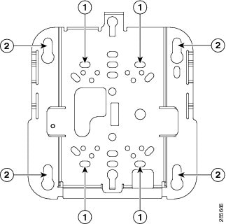
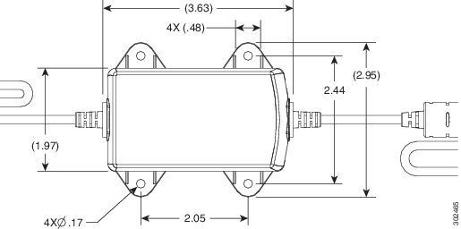
Step 1![]() Use the mounting bracket as a template to mark the locations of the mounting holes on the bracket. Figure 2-15 shows details of the mounting bracket.
Use the mounting bracket as a template to mark the locations of the mounting holes on the bracket. Figure 2-15 shows details of the mounting bracket.
Figure 2-15 Universal Mounting Bracket Details
Step 2![]() Use a #29 drill (0.1360 inch [3.4772 mm]) bit to drill a pilot hole at the mounting hole locations you marked.
Use a #29 drill (0.1360 inch [3.4772 mm]) bit to drill a pilot hole at the mounting hole locations you marked.
Note![]() The pilot hole size varies according to the material and thickness you are fastening. It is recommended to test the material to determine the ideal hole size for your mounting application.
The pilot hole size varies according to the material and thickness you are fastening. It is recommended to test the material to determine the ideal hole size for your mounting application.
Step 3![]() (Optional) Drill or cut a cable access hole near and below the location of the mounting bracket cable access cover large enough for the Ethernet cable, building ground wire, and power cables.
(Optional) Drill or cut a cable access hole near and below the location of the mounting bracket cable access cover large enough for the Ethernet cable, building ground wire, and power cables.
Step 4![]() Pull approximately 9 inches of cable through the hole.
Pull approximately 9 inches of cable through the hole.
Step 5![]() Route the Ethernet and power cables through the bracket before you attach the bracket to the ceiling or wall.
Route the Ethernet and power cables through the bracket before you attach the bracket to the ceiling or wall.
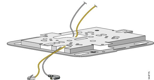
Step 6![]() Route the cables through the main cable access hole and then through the smaller access hole as shown in Figure 2-16.
Route the cables through the main cable access hole and then through the smaller access hole as shown in Figure 2-16.
Figure 2-16 Routing the Ethernet and Power Cables
Step 7![]() (Optional) Use the ground screw to attach the building ground wire to the ground location on the base of the router. See the “Grounding the Cisco 812 ISR” section for the general grounding instructions.
(Optional) Use the ground screw to attach the building ground wire to the ground location on the base of the router. See the “Grounding the Cisco 812 ISR” section for the general grounding instructions.
Step 8![]() Position the mounting bracket mounting holes (with indents down) over the pilot holes.
Position the mounting bracket mounting holes (with indents down) over the pilot holes.
Step 9![]() Insert a fastener into each mounting hole and tighten.
Insert a fastener into each mounting hole and tighten.
Step 10![]() Connect the Ethernet and power cables to the router.
Connect the Ethernet and power cables to the router.
Step 11![]() Align the router feet with the large part of the keyhole mounting slots on the mounting plate.
Align the router feet with the large part of the keyhole mounting slots on the mounting plate.
Step 12![]() Gently slide the router onto the mounting bracket keyhole slots until it clicks into place.
Gently slide the router onto the mounting bracket keyhole slots until it clicks into place.
Mounting the Cisco 812 ISR to a Network or Electrical Box
To mount the Cisco 812 ISR to a network box or an electrical box, perform these steps:
Step 1![]() Position the universal mounting bracket (C810-BR-CM) over the existing network or electrical box and align the bracket mounting holes with the box holes.
Position the universal mounting bracket (C810-BR-CM) over the existing network or electrical box and align the bracket mounting holes with the box holes.
Step 2![]() Hold the mounting bracket in place and insert a 6-32 x 0.18-inch pan head screw into each of the mounting holes and tighten.
Hold the mounting bracket in place and insert a 6-32 x 0.18-inch pan head screw into each of the mounting holes and tighten.
Step 3![]() Pull approximately 9 inches of Ethernet and power cable through the hole.
Pull approximately 9 inches of Ethernet and power cable through the hole.
Step 4![]() Route the cables through the bracket before you attach the bracket to the ceiling.
Route the cables through the bracket before you attach the bracket to the ceiling.
Step 5![]() Route the cables through the main cable access hole and then through the smaller access hole as shown in Figure 2-16.
Route the cables through the main cable access hole and then through the smaller access hole as shown in Figure 2-16.
Step 6![]() (Optional) Use the ground screw to attach the building ground wire to the ground location on the base of the router. See the “Grounding the Cisco 812 ISR” section for the general grounding instructions.
(Optional) Use the ground screw to attach the building ground wire to the ground location on the base of the router. See the “Grounding the Cisco 812 ISR” section for the general grounding instructions.
Step 7![]() Connect the Ethernet and power cables to the router.
Connect the Ethernet and power cables to the router.
Step 8![]() Align the router feet over the keyhole mounting slots on the optional mounting bracket.
Align the router feet over the keyhole mounting slots on the optional mounting bracket.
Step 9![]() Slide the router onto the optional mounting bracket until it clicks into place.
Slide the router onto the optional mounting bracket until it clicks into place.
Grounding the Cisco 812 ISR
Grounding is not always required for indoor installations because the Cisco 812 ISR is classified as a low-voltage device and does not contain internal power supplies. However, it is recommended that you check your local and national electrical codes to see if grounding is a requirement. If grounding is required in your area or you wish to ground your router, perform the following steps:
Warning![]() Use copper conductors only. Statement 1025
Use copper conductors only. Statement 1025
Warning![]() This equipment must be grounded. Never defeat the ground conductor or operate the equipment in the absence of a suitably installed ground conductor. Contact the appropriate electrical inspection authority or an electrician if you are uncertain that suitable grounding is available. Statement 1024
This equipment must be grounded. Never defeat the ground conductor or operate the equipment in the absence of a suitably installed ground conductor. Contact the appropriate electrical inspection authority or an electrician if you are uncertain that suitable grounding is available. Statement 1024
Warning![]() When installing or replacing the unit, the ground connection must always be made first and disconnected last. Statement 1046
When installing or replacing the unit, the ground connection must always be made first and disconnected last. Statement 1046
Warning![]() This equipment needs to be grounded. Use a green and yellow 14 to 18 AWG ground wire to connect the host to earth ground during normal use. Statement 242
This equipment needs to be grounded. Use a green and yellow 14 to 18 AWG ground wire to connect the host to earth ground during normal use. Statement 242
Step 1![]() Find a suitable building grounding point as close to the router as possible.
Find a suitable building grounding point as close to the router as possible.
Step 2![]() Connect a user-supplied ground wire to the building grounding point. The wire should be a minimum of #14AWG assuming a circuit length of 25 feet (30.5 cm). Consult your local electrical codes for additional information.
Connect a user-supplied ground wire to the building grounding point. The wire should be a minimum of #14AWG assuming a circuit length of 25 feet (30.5 cm). Consult your local electrical codes for additional information.
Step 3![]() Route the ground wire to the router.
Route the ground wire to the router.
Step 4![]() Attach the wire to a suitable grounding ring lug.
Attach the wire to a suitable grounding ring lug.
Step 5![]() Crimp or solder the wire to the lug.
Crimp or solder the wire to the lug.
Step 6![]() Use a Phillips screwdriver to remove the existing 6-32 screw at the grounding location as shown in Figure 2-17.
Use a Phillips screwdriver to remove the existing 6-32 screw at the grounding location as shown in Figure 2-17.
Figure 2-17 Connecting the Ring Lug onto the Grounding Point
|
|
|
|
|
Step 7![]() Connect the ring lug to the router grounding point and reinstall the same 6-32 screw.
Connect the ring lug to the router grounding point and reinstall the same 6-32 screw.
Installing the Cisco 819 ISR
This section describes the equipment and the procedures for successfully installing the Cisco 819 ISR and contains the following sections:
Note![]() For compliance and safety information, see the Regulatory Compliance and Safety Information Roadmap that ships with the router and the Regulatory Compliance and Safety Information for Cisco 800 Series Routers.
For compliance and safety information, see the Regulatory Compliance and Safety Information Roadmap that ships with the router and the Regulatory Compliance and Safety Information for Cisco 800 Series Routers.
Warning![]() Read the installation instructions before connecting the system to the power source. Statement 1004
Read the installation instructions before connecting the system to the power source. Statement 1004
Warning![]() This equipment must be grounded. Never defeat the ground conductor or operate the equipment in the absence of a suitably installed ground conductor. Contact the appropriate electrical inspection authority or an electrician if you are uncertain that suitable grounding is available. Statement 1024
This equipment must be grounded. Never defeat the ground conductor or operate the equipment in the absence of a suitably installed ground conductor. Contact the appropriate electrical inspection authority or an electrician if you are uncertain that suitable grounding is available. Statement 1024
Warning![]() Only trained and qualified personnel should be allowed to install, replace, or service this equipment. Statement 1030
Only trained and qualified personnel should be allowed to install, replace, or service this equipment. Statement 1030
Warning![]() No user-serviceable parts inside. Do not open. Statement 1073
No user-serviceable parts inside. Do not open. Statement 1073
Warning![]() Ultimate disposal of this product should be handled according to all national laws and regulations. Statement 1040
Ultimate disposal of this product should be handled according to all national laws and regulations. Statement 1040
Warning![]() Read the wall-mounting instructions carefully before beginning installation. Failure to use the correct hardware or to follow the correct procedures could result in a hazardous situation to people and damage to the system. Statement 378
Read the wall-mounting instructions carefully before beginning installation. Failure to use the correct hardware or to follow the correct procedures could result in a hazardous situation to people and damage to the system. Statement 378
Warning![]() The covers are an integral part of the safety design of the product. Do not operate the unit without the covers installed. Statement 1077
The covers are an integral part of the safety design of the product. Do not operate the unit without the covers installed. Statement 1077
Warning![]() Do not locate the antenna near overhead power lines or other electric light or power circuits, or where it can come into contact with such circuits. When installing the antenna, take extreme care not to come into contact with such circuits, because they may cause serious injury or death. For proper installation and grounding of the antenna, please refer to national and local codes (for example, U.S.:NFPA 70, National Electrical Code, Article 810, Canada: Canadian Electrical Code, Section 54). Statement 1052
Do not locate the antenna near overhead power lines or other electric light or power circuits, or where it can come into contact with such circuits. When installing the antenna, take extreme care not to come into contact with such circuits, because they may cause serious injury or death. For proper installation and grounding of the antenna, please refer to national and local codes (for example, U.S.:NFPA 70, National Electrical Code, Article 810, Canada: Canadian Electrical Code, Section 54). Statement 1052
Warning![]() This product is not intended to be directly connected to the Cable Distribution System. Additional regulatory compliance and legal requirements may apply for direct connection to the Cable Distribution System. This product may connect to the Cable Distribution System ONLY through a device that is approved for direct connection. Statement 1078
This product is not intended to be directly connected to the Cable Distribution System. Additional regulatory compliance and legal requirements may apply for direct connection to the Cable Distribution System. This product may connect to the Cable Distribution System ONLY through a device that is approved for direct connection. Statement 1078
Equipment, Tools, and Connections
This section describes the equipment, tools, and connections necessary for installing your Cisco 819 ISR. It contains the following topics:
Items Shipped with your Router
Unpack the box and verify that all items listed on the invoice were shipped with the Cisco 819 ISR.
The following items are shipped with your router:
- AC power supply (default)
- AC power supply cable (default)
- Cisco Configuration Professional (Cisco CP) CD
- DC power supply (optional)
- Power cord retention lock (available in Cisco 819HGW, Cisco 819HWD, Cisco 819HG-4G, and Cisco 819G-4G ISRs only)
- Power switch lock (available in Cisco 819HGW, Cisco 819HWD, and Cisco 819HG-4G ISRs only)
- Straight-through RJ-45 Ethernet cable
- Two cellular multiband swivel mount dipole antennas
- Three WiFi antennas for Cisco 819HGW and Cisco 819HWD ISRs
Note![]() AC or DC Power supply is included based on the your order.
AC or DC Power supply is included based on the your order.
Additional Items
The following items are not shipped with the router but are required for installation:
- ESD-preventive cord and wrist strap.
- Screws for mounting the router on a wall.
- Two number-10 wood screws (round- or pan-head) with number-10 washers or two number-10 washer-head screws, for mounting on a wall stud. The screws must be long enough to penetrate at least 3/4 inch (20 mm) into the supporting wood or metal wall stud.
- Two number-10 wall anchors with washers, for mounting the router on a hollow wall.
- Wire crimper for chassis grounding.
- Wire for connecting the chassis to an earth ground.
- AWG 14 (2 mm2) or larger wire for NEC-compliant chassis grounding.
- AWG 18 (1 mm2) or larger wire for EN/IEC 60950–compliant chassis grounding.
- Ring terminal with an inner diameter of 1/4 inch. (5 to 7 mm) for NEC-compliant chassis grounding. Ring terminal used for grounding needs to be listed and suitable for 14 to 18AWG. Lock washer needs to be added to ring terminal ground installation when not using power switch lock.
- Ethernet cables for connecting to the Fast Ethernet (FE) WAN and LAN ports.
Connections
Obtain a broadband or Ethernet connection from your service provider.
Ethernet Devices
Identify the Ethernet devices that you will connect to the router: hub, servers, and workstations or PCs. Ensure that each device has a network interface card (NIC) for connecting to Ethernet ports.
If you plan to configure the software using Cisco IOS commands through the console port, provide an ASCII terminal or a PC that is running terminal emulation software to connect to the console port.
If you plan to connect a modem, provide the modem and modem cable.
Installing the Router
This section describes how to install the Cisco 819 ISR. These routers can be installed on a table top or other flat horizontal surface mounted on a wall or DIN rail.
The recommended clearance when horizontally mounted is 1.5 inches on both sides for floor mount bracket clearance and 2 inches on top. Top clearance is not required but stacking heat-dissipating objects on top of the router is not allowed. I/O side clearance is needed as it is required to access the cable connections. Clearance is not required on the backside (opposite side from I/O face) unless DIN rail mounting is required. Clearance is required to attach and mount the DIN rail bracket. The same clearances apply when mounted vertically.
This section also describes how to attach external antennas to the routers and contains the following topics:
Warnings
Warning![]() This equipment needs to be grounded. Use a green and yellow 14 to 18 AWG ground wire to connect the host to earth ground during normal use. Statement 242
This equipment needs to be grounded. Use a green and yellow 14 to 18 AWG ground wire to connect the host to earth ground during normal use. Statement 242
Warning![]() This equipment must be grounded. Never defeat the ground conductor or operate the equipment in the absence of a suitably installed ground conductor. Contact the appropriate electrical inspection authority or an electrician if you are uncertain that suitable grounding is available. Statement 1024
This equipment must be grounded. Never defeat the ground conductor or operate the equipment in the absence of a suitably installed ground conductor. Contact the appropriate electrical inspection authority or an electrician if you are uncertain that suitable grounding is available. Statement 1024
Warning![]() Read the wall-mounting instructions carefully before beginning installation. Failure to use the correct hardware or to follow the correct procedures could result in a hazardous situation to people and damage to the system. Statement 378
Read the wall-mounting instructions carefully before beginning installation. Failure to use the correct hardware or to follow the correct procedures could result in a hazardous situation to people and damage to the system. Statement 378
Warning![]() Do not cover or obstruct the router vents located on both sides of the router; otherwise, overheating could occur and cause damage to the router.
Do not cover or obstruct the router vents located on both sides of the router; otherwise, overheating could occur and cause damage to the router.
Warning![]() Do not place anything on top of the router that weighs more than 10 pounds (4.5 kilograms), and do not stack routers on a desktop. Excessive weight on top of the router could damage the chassis.
Do not place anything on top of the router that weighs more than 10 pounds (4.5 kilograms), and do not stack routers on a desktop. Excessive weight on top of the router could damage the chassis.
Warning![]() Do not install the router or power supplies next to a heat source of any kind, including heating vents.
Do not install the router or power supplies next to a heat source of any kind, including heating vents.
Warning![]() The intra-building port(s) of the equipment or subassembly is suitable for connection to intra-building or unexposed wiring or cabling only. The intra-building port(s) of the equipment or subassembly MUST NOT metallically connect to interfaces that connect to the OSP or its wiring. These interfaces are designed for use as intra-building interfaces only (Type 2 or Type 4 ports as described in GR-1089-CORE, Issue 5) and require isolation from the exposed OSP cabling. The addition of Primary Protectors is not sufficient protection in order to connect these interfaces metallically to OSP wiring.
The intra-building port(s) of the equipment or subassembly is suitable for connection to intra-building or unexposed wiring or cabling only. The intra-building port(s) of the equipment or subassembly MUST NOT metallically connect to interfaces that connect to the OSP or its wiring. These interfaces are designed for use as intra-building interfaces only (Type 2 or Type 4 ports as described in GR-1089-CORE, Issue 5) and require isolation from the exposed OSP cabling. The addition of Primary Protectors is not sufficient protection in order to connect these interfaces metallically to OSP wiring.
Warning![]() The intra-building port(s) (list the port or ports) of the equipment or subassembly must use shielded intra-building cabling/wiring that is grounded at both ends.
The intra-building port(s) (list the port or ports) of the equipment or subassembly must use shielded intra-building cabling/wiring that is grounded at both ends.
Accessing the SIM Card
This section describes how to install and replace the SIM card. Ensure that the router is not mounted to a wall, floor, or DIN rail.
Warning![]() Hot surface. Statement 1079
Hot surface. Statement 1079
To access the SIM card in the Cisco 819 ISR, follow these steps:
Step 1![]() Power off the router and disconnect the power cable from the power source.
Power off the router and disconnect the power cable from the power source.
Step 2![]() Place the router on its side and ensure that any installed antennas are carefully oriented.
Place the router on its side and ensure that any installed antennas are carefully oriented.
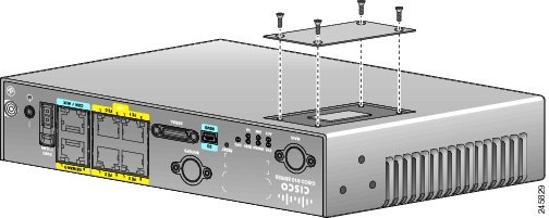
Step 3![]() Remove the SIM access panel using four flat head #6 screws. (See Figure 2-18.)
Remove the SIM access panel using four flat head #6 screws. (See Figure 2-18.)
Figure 2-18 Accessing the SIM Cards
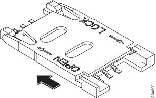
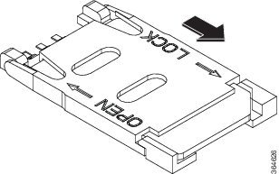
Step 4![]() To open the SIM socket cover, slide the cover in the direction of the open arrow. (See Figure 2-19.)
To open the SIM socket cover, slide the cover in the direction of the open arrow. (See Figure 2-19.)
Figure 2-19 Opening the SIM Socket Cover
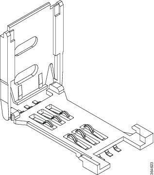
Step 5![]() Gently lift the cover on its hinges. (See Figure 2-20.)
Gently lift the cover on its hinges. (See Figure 2-20.)
Figure 2-20 Lifting the Socket Cover
Step 6![]() Slide the SIM card into the slot in the cover. Gently push down the cover to close. The SIM card will come in contact with the metal contacts in the socket. (See Figure 2-21.)
Slide the SIM card into the slot in the cover. Gently push down the cover to close. The SIM card will come in contact with the metal contacts in the socket. (See Figure 2-21.)
Figure 2-21 Sliding the SIM Card into the Slot

Step 7![]() To lock the cover, slide it in the direction of the lock arrow. (See Figure 2-22.)
To lock the cover, slide it in the direction of the lock arrow. (See Figure 2-22.)
Figure 2-22 Locking the SIM Socket Cover
Step 8![]() Replace the panel and the screws.
Replace the panel and the screws.
Installing Antennas
Note![]() Before you install the Cisco 819 ISR on a table, wall, or DIN rail, install the antennas on the front panel. It is difficult to install the antennas after the router is installed.
Before you install the Cisco 819 ISR on a table, wall, or DIN rail, install the antennas on the front panel. It is difficult to install the antennas after the router is installed.
To attach the radio antennas to your wireless router, follow these steps:
Step 1![]() Manually screw the antenna tight to the TNC connectors on the back of the router. (See Figure 2-23.)
Manually screw the antenna tight to the TNC connectors on the back of the router. (See Figure 2-23.)
Figure 2-23 Installing the Antenna
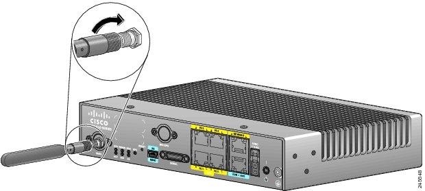
Step 2![]() Orient the antennas. For optimum wireless performance, antennas should be generally perpendicular to each other.
Orient the antennas. For optimum wireless performance, antennas should be generally perpendicular to each other.
If the router is being mounted on a desk, orient the antennas straight up.
Installing a WiFi External Antenna
This section describes how to install a WiFi external antenna.
Step 1![]() Table 1-13 and Table 1-15 .
Table 1-13 and Table 1-15 .
Step 2![]() Rotate the knurled portion of the WiFi external antenna clockwise to screw the antenna to the RP-TNC. (See Figure 2-24.)
Rotate the knurled portion of the WiFi external antenna clockwise to screw the antenna to the RP-TNC. (See Figure 2-24.)
Note![]() WiFi antennas should be generally perpendicular to each other to achieve best coverage.
WiFi antennas should be generally perpendicular to each other to achieve best coverage.
Figure 2-24 Cisco WiFi Antenna Assembly
|
|
|
||
|
|
|
Installing on a Table
To install the router on a table or other flat horizontal surface, firmly place the router on a table or other horizontal surface. Keep at least 1 inch (2.5 centimeters) of clear space for heat dissipation.
Connect the chassis to a reliable earth ground. For the chassis ground connection procedures, see the “Installing the Router Using the Configurable Low Profile DIN Mount” section.
Mounting on a Wall
The Cisco 819 ISR has mounting holes on the bottom of the chassis for mounting the unit on a wall or other vertical surface.

Tip![]() When choosing a location for wall-mounting the router, consider cable limitations and wall structure.
When choosing a location for wall-mounting the router, consider cable limitations and wall structure.
To mount the router on a wall, follow these steps:
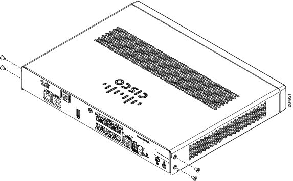
Step 1![]() Remove the screws on the sides of the routers.
Remove the screws on the sides of the routers.
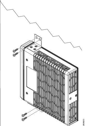
Step 2![]() Attach the standard brackets to the chassis using the three screws provided for each bracket. (See Figure 2-25.)
Attach the standard brackets to the chassis using the three screws provided for each bracket. (See Figure 2-25.)
Figure 2-25 Attaching the Standard Brackets
Step 3![]() Install the router to a wall stud using two number-10 wood screws, round- or pan-head, with number-10 washers or two number-10 washer-head screws. The screws must be long enough to penetrate at least 1.0 inch (25.4 mm) into the supporting wood or metal wall stud. (See Figure 2-26.) Tighten the screws to a torque of 6 to 8 inch-pound.
Install the router to a wall stud using two number-10 wood screws, round- or pan-head, with number-10 washers or two number-10 washer-head screws. The screws must be long enough to penetrate at least 1.0 inch (25.4 mm) into the supporting wood or metal wall stud. (See Figure 2-26.) Tighten the screws to a torque of 6 to 8 inch-pound.
Note![]() The orientation of the Cisco 819 ISR products is critical when wall-mounting. The router must be oriented as shown in Figure 2-26 with the left side of the router rotated up (as viewed from the IO side) to comply with IP41 and safety criteria. No other wall mounting orientation is supported.
The orientation of the Cisco 819 ISR products is critical when wall-mounting. The router must be oriented as shown in Figure 2-26 with the left side of the router rotated up (as viewed from the IO side) to comply with IP41 and safety criteria. No other wall mounting orientation is supported.
Note![]() The mounting brackets (PID number ACS-810-FWM) are not included in the package of C819G series routers.
The mounting brackets (PID number ACS-810-FWM) are not included in the package of C819G series routers.
Figure 2-26 Installing the Router to the Wall
Note![]() For hollow-wall mounting, each bracket requires two wall anchors with washers. Wall anchors and washers must be size number 10.
For hollow-wall mounting, each bracket requires two wall anchors with washers. Wall anchors and washers must be size number 10.
Step 4![]() Route the cables so that they do not put a strain on the connectors or mounting hardware.
Route the cables so that they do not put a strain on the connectors or mounting hardware.
To comply with IP 41, cables should be routed down relative to the router to prevent water from travelling on the cables.
Installing a DIN Rail
You can use either the 7.5-mm or the 15-mm thick DIN rail for the Cisco 819 ISR. Secure the DIN rail to the mounting surface approximately every 7.8 inches (200 mm) and use end-anchors appropriately.
Note![]() DIN rail mounting is not supported on Cisco 819GW, Cisco 819HGW, and Cisco 819HWD ISRs.
DIN rail mounting is not supported on Cisco 819GW, Cisco 819HGW, and Cisco 819HWD ISRs.
To attach the Cisco 819 ISR to a 35-mm wide DIN rail, follow these steps.
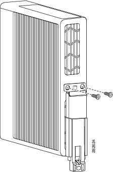
Step 1![]() Attach the DIN rail to the back of the router using the three screws provided. (See Figure 2-27.)
Attach the DIN rail to the back of the router using the three screws provided. (See Figure 2-27.)
Figure 2-27 Attaching the DIN Rail to the Cisco 819 ISR
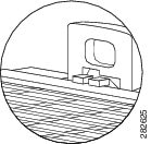
Step 2![]() Find the tab on the end of the DIN rail that extends past the router. (See Figure 2-28.) Press the tab in and slide the DIN rail out while the tab is pressed down.
Find the tab on the end of the DIN rail that extends past the router. (See Figure 2-28.) Press the tab in and slide the DIN rail out while the tab is pressed down.
Step 3![]() Turn the router sideways so that the antenna is at the top.
Turn the router sideways so that the antenna is at the top.
Step 4![]() Position the rear edge of the router directly in front of the DIN rail, making sure that the DIN rail fits in the space between the latch and hook.
Position the rear edge of the router directly in front of the DIN rail, making sure that the DIN rail fits in the space between the latch and hook.
Step 5![]() Position the router so that the hook on the DIN rail bracket hooks onto the top edge of the DIN rail. The weight of the product can rest on the hook temporarily while the DIN rail bracket latches are secured.
Position the router so that the hook on the DIN rail bracket hooks onto the top edge of the DIN rail. The weight of the product can rest on the hook temporarily while the DIN rail bracket latches are secured.
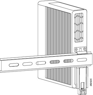
Step 6![]() Push the DIN rail bracket latch up after the router is over the DIN rail to secure it. The router is now installed in the DIN rail. (See Figure 2-29.)
Push the DIN rail bracket latch up after the router is over the DIN rail to secure it. The router is now installed in the DIN rail. (See Figure 2-29.)
Figure 2-29 Cisco 819 ISR Installed with the DIN Rail
Installing the Router Using the Configurable Low Profile DIN Mount
If space is limited between the DIN rail and the enclosure cover, the Configurable Low Profile DIN Mount can be utilized to mount the router flat against the DIN rail. It can also be configured in three different ways to allow router cabling to exit from the bottom, right or left.
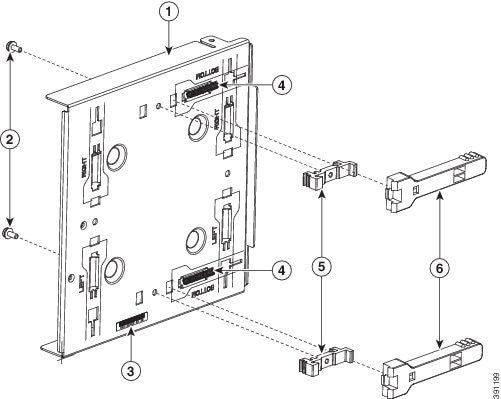
Figure 2-30 Configurable Low Profile DIN Mount standard configuration
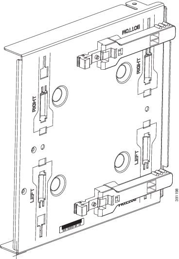
Figure 2-31 Low Profile DIN Mount Configuration
|
|
|
||
|
|
|
||
|
|
|
The mount comes configured in a bottom cable exit position, with the rail latches in the slots marked Bottom. To reconfigure the mount:
1.![]() Remove the two DIN Rail Latch Bracket Screws (Item 2).
Remove the two DIN Rail Latch Bracket Screws (Item 2).
2.![]() Slide the DIN Rail Latch Brackets (Item 5) and DIN Rail Latch (Item 6) against the spring pressure, towards the edge of the tray and remove the bracket and latch assembly. Be careful not to lose the springs.
Slide the DIN Rail Latch Brackets (Item 5) and DIN Rail Latch (Item 6) against the spring pressure, towards the edge of the tray and remove the bracket and latch assembly. Be careful not to lose the springs.
3.![]() Remove the DIN Rail Latch Springs (Item 4)
Remove the DIN Rail Latch Springs (Item 4)
4.![]() Identify the desired mounting configuration and replace the latch assemblies in slots with the matching labels, using the reverse order of steps 1 through 3.
Identify the desired mounting configuration and replace the latch assemblies in slots with the matching labels, using the reverse order of steps 1 through 3.
Attaching the mount to the router
Figure 2-32 Cisco ISR 819 mounted in a Configurable Low Profile DIN mount
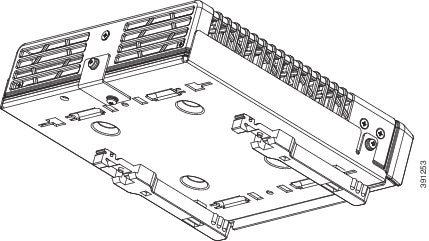
To attach the router to the mount:
1. Remove the bottom screw of the 3 screws on the sides of the router at the front.
2. Slip the router into the mount tray
3. Align the holes at the front sides of the mount with the vacant screw holes on the router and screw the mount to the router with the longer, 6-32 x.375 Philips/Pan Head screws with locking washer (Cisco 48-0422-01), which are included with the kit.
4. Remove the screw near the middle on the back of the router
5. Locate the “L” bracket that came with the mount, and screw the bracket to the router with the other 6-32 x.375 Philips/Pan Head screw and locking washer (Cisco 48-0422-01).
6. Now screw the bracket to the mount with the shorter, supplied, 6-32 x.25 Philips/Pan Head screw and locking washer (Cisco 48-0421-01).
Attaching the Assembled Router and Configurable DIN Mount to the DIN Rail
Once the mount has been configured according to need, and the router has been attached to the mount, the assembly is ready to be snapped onto the DIN rail.
Installing the Router Ground Connection
The router must be connected to a reliable earth ground. Install the ground wire in accordance with local electrical safety standards.
Note![]() This section does not apply to C866VAE and C867VAE series devices.
This section does not apply to C866VAE and C867VAE series devices.
- For NEC-compliant grounding, use size 14 AWG (2 mm2) or larger copper wire and a ring terminal with an inner diameter of 1/4 in. (5 to 7 mm).
- For EN/IEC 60950-compliant grounding, use size 18 AWG (1 mm2) or larger copper wire.
Warning![]() This equipment needs to be grounded. Use a green and yellow 14 to 18 AWG ground wire to connect the host to earth ground during normal use. Statement 242
This equipment needs to be grounded. Use a green and yellow 14 to 18 AWG ground wire to connect the host to earth ground during normal use. Statement 242
To install the ground connection, follow these steps:
Step 1![]() Strip one end of the ground wire to the length required for the terminal.
Strip one end of the ground wire to the length required for the terminal.
Step 2![]() Crimp the ground wire to the ring terminal using the wire crimper.
Crimp the ground wire to the ring terminal using the wire crimper.
Step 3![]() If you choose to install the power switch lock, perform Step 5
If you choose to install the power switch lock, perform Step 5![]() to Step 7
to Step 7![]() . Otherwise, perform Step 4
. Otherwise, perform Step 4![]() , Step 6
, Step 6![]() and Step 7
and Step 7![]() .
.
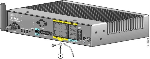
Step 4![]() Attach the ring terminal to the chassis. Use the single screw provided. Tighten the screws to a torque of 8 to 10 inch-pound (0.9 to 1.1 newton meter). (See Figure 2-33.)
Attach the ring terminal to the chassis. Use the single screw provided. Tighten the screws to a torque of 8 to 10 inch-pound (0.9 to 1.1 newton meter). (See Figure 2-33.)
Figure 2-33 Chassis Ground Connection Using Ring Terminal
|
|
|
Step 5![]() Install the power switch lock, see the “Installing the Power Switch Lock” section. Tighten the screws to a torque of 8 to 10 in-lb (0.9 to 1.1 N-m). Torque the hex standoff to the same torque.
Install the power switch lock, see the “Installing the Power Switch Lock” section. Tighten the screws to a torque of 8 to 10 in-lb (0.9 to 1.1 N-m). Torque the hex standoff to the same torque.
Step 6![]() Connect the other end of the ground wire to a known reliable earth ground point at your site.
Connect the other end of the ground wire to a known reliable earth ground point at your site.
Step 7![]() If you are using this router in a vehicle, attach the ring terminal to the chassis using one of the screws provided and the green or green and yellow striped wire. Connect the other end of the wire to the vehicle ground.
If you are using this router in a vehicle, attach the ring terminal to the chassis using one of the screws provided and the green or green and yellow striped wire. Connect the other end of the wire to the vehicle ground.
After you install and properly ground the router, you can connect the power wiring, the LAN cables, and the cables for administrative access as required for your installation.
Installing the Power Cord Retention Lock
The Cisco 819 ISRs have a power cord retention mechanism as an accessory. It locks the power cord to the router so when a user accidentally pulls out the power cord, the power cord will not come out from the router. For the complete list of Cisco 819 ISRs that support power cord retention lock, see Table 1-7.
This section describes how to install the power cord retention lock.
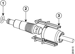
Step 1![]() Pre-assemble the o-ring onto the barrel of the power cord as shown in Figure 2-34.
Pre-assemble the o-ring onto the barrel of the power cord as shown in Figure 2-34.
Figure 2-34 Pre-assemble the O-Ring onto the Barrel
|
|
|
||
|
|
|
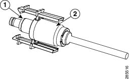
Step 2![]() Place the power cord lock onto the power cord behind the connector overmold as shown in Figure 2-35. Slide the power cord lock forward so that it captures the overmold and is fully seated.
Place the power cord lock onto the power cord behind the connector overmold as shown in Figure 2-35. Slide the power cord lock forward so that it captures the overmold and is fully seated.
Figure 2-35 Place the Power Cord Lock onto the Power Cord
|
|
|
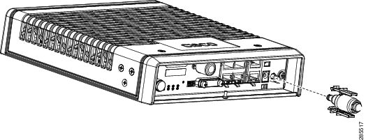
Step 3![]() Install the power cord with power cord lock and the pre-installed o-ring to mate with the power jack on the router while making sure that the two arms of the power cord lock slide into the corresponding slots on the router and are fully seated with both arms locking into the slots as shown in Figure 2-36.
Install the power cord with power cord lock and the pre-installed o-ring to mate with the power jack on the router while making sure that the two arms of the power cord lock slide into the corresponding slots on the router and are fully seated with both arms locking into the slots as shown in Figure 2-36.
Figure 2-36 Installing Power Cord Lock onto the Router
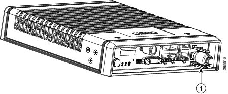
Step 4![]() To remove the power cord lock, use your thumb and index fingers to squeeze ends of tabs while pulling away from the router. (See Figure 2-37.)
To remove the power cord lock, use your thumb and index fingers to squeeze ends of tabs while pulling away from the router. (See Figure 2-37.)
|
|
Installing the Power Switch Lock
The Cisco 819 ISRs have a power switch lock as an accessory. The power switch lock prevents unauthorized access to a tampered proof router (for example, router in a bus). For the complete list of Cisco 819 ISRs that support power switch lock, see Table 1-7.
This section describes how to install the power switch lock.
Step 1![]() Install the power switch lock by following the parts listed in Figure 2-38.
Install the power switch lock by following the parts listed in Figure 2-38.
All these parts are in the accessory kit in their own bag. The ring terminal does not have to be installed.
Figure 2-39 shows the power switch lock installed.
Figure 2-38 Installing Power Switch Lock
|
|
|
||
|
|
|
||
|
|
|
Figure 2-39 Power Switch Lock Installed
Mounting the DC Power Supply
Note![]() This equipment is suitable for installation in Network Telecommunications Facilities and locations where the NEC applies. This equipment is suitable for installations as part of the Common Bonding Network (CBN).
This equipment is suitable for installation in Network Telecommunications Facilities and locations where the NEC applies. This equipment is suitable for installations as part of the Common Bonding Network (CBN).
Note![]() The Battery Return (BR) input terminal shall be an isolated DC return (DC-I). The DC return terminal or conductor shall not be connected to the equipment frame or the grounding means of the equipment. DC-powered products have a nominal operating DC voltage of 24 and 48 VDC. Reference American National Standard for Telecommunications (ATIS) 0600315.
The Battery Return (BR) input terminal shall be an isolated DC return (DC-I). The DC return terminal or conductor shall not be connected to the equipment frame or the grounding means of the equipment. DC-powered products have a nominal operating DC voltage of 24 and 48 VDC. Reference American National Standard for Telecommunications (ATIS) 0600315.
Warning![]() Read the wall-mounting instructions carefully before beginning installation. Failure to use the correct hardware or to follow the correct procedures could result in a hazardous situation to people and damage to the system. Statement 378
Read the wall-mounting instructions carefully before beginning installation. Failure to use the correct hardware or to follow the correct procedures could result in a hazardous situation to people and damage to the system. Statement 378
The Cisco 800 ISR DC power supply may be mounted to a wall using four #6 pan- or round-head wood screws for the mounting holes on the supply.
- For attaching to a wall stud, the power supply requires #6 wood screws (round- or pan-head). The screws must be long enough to penetrate and tap at least 0.75 inches (19.1 mm) into the supporting wood or metal wall stud.
- For hollow-wall mounting, the power supply requires the use of appropriate-sized wall anchors that work with the drywall thickness the unit is to be installed in. Use hollow-wall anchors that support using #6 screws and use #6 pan- or round-head screws to secure the power supply to the wall. Each wall anchor should be rated for at least 30 lbs.
Figure 2-40 DC Power Supply Wall-Mounting
To mount the DC power supply (PID: PWR2-20W-12VDC and Part Number: 341-0548-02) to the wall, follow these instructions:
Step 1![]() Install the four screws into the mounting holes on the DC power supply (see Figure 2-40) before being secured to the wall studs or wall anchors.
Install the four screws into the mounting holes on the DC power supply (see Figure 2-40) before being secured to the wall studs or wall anchors.
Step 2![]() Hang the DC power supply by securing the screws to the wall stud or into the wall anchors.
Hang the DC power supply by securing the screws to the wall stud or into the wall anchors.
Note![]() The DC supply is IP 41 compliant in all six orthogonal directions. The mounting orientation will not affect IP 41 compliance.
The DC supply is IP 41 compliant in all six orthogonal directions. The mounting orientation will not affect IP 41 compliance.
Figure 2-41 DC Power Supply Wall-Mounting
To mount the DC power supply (PID: PWR2-22W-20-60 and Part Number: 341-100360-01) to the wall, follow these instructions:
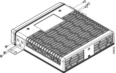
Step 1![]() Attach the four corner brackets to the DC power module using the screws provided for each bracket (see Figure 2-41).
Attach the four corner brackets to the DC power module using the screws provided for each bracket (see Figure 2-41).
Step 2![]() Install the power module to a wall stud using the remaining screws provided for the brackets.
Install the power module to a wall stud using the remaining screws provided for the brackets.
Installing the Cisco 860, 880, 890 ISR
This section describes the equipment and the procedures for successfully installing the Cisco 860 series, 880 series, and 890 series ISRs, and contains the following sections:
- Equipment, Tools, and Connections
- Installing the Cisco 860, 880, and 890 Series Routers
- Installing the C881G-B/S/V-K9 ISR
- Installing the C881GW-S/V-A-K9 ISR
- Installing the C881G-U-K9 ISR
- Installing the Cisco 880G for 3.7G (HSPA+)/3.5G (HSPA) ISRs
Note![]() For compliance and safety information, see the Regulatory Compliance and Safety Information Roadmap that ships with the router and the Regulatory Compliance and Safety Information for Cisco 800 Series Routers.
For compliance and safety information, see the Regulatory Compliance and Safety Information Roadmap that ships with the router and the Regulatory Compliance and Safety Information for Cisco 800 Series Routers.
Warning![]() All wireless LAN products in the 5.2/5.3GHz band cannot be used outdoors. Use the product only indoors. Statement 372
All wireless LAN products in the 5.2/5.3GHz band cannot be used outdoors. Use the product only indoors. Statement 372
Warning![]() Read the installation instructions before connecting the system to the power source. Statement 1004
Read the installation instructions before connecting the system to the power source. Statement 1004
Warning![]() Only trained and qualified personnel should be allowed to install, replace, or service this equipment. Statement 1030
Only trained and qualified personnel should be allowed to install, replace, or service this equipment. Statement 1030
Warning![]() Ultimate disposal of this product should be handled according to all national laws and regulations. Statement 1040
Ultimate disposal of this product should be handled according to all national laws and regulations. Statement 1040
Warning![]() Do not locate the antenna near overhead power lines or other electric light or power circuits, or where it can come into contact with such circuits. When installing the antenna, take extreme care not to come into contact with such circuits, because they may cause serious injury or death. For proper installation and grounding of the antenna, please refer to national and local codes (for example, U.S.:NFPA 70, National Electrical Code, Article 810, Canada: Canadian Electrical Code, Section 54). Statement 1052
Do not locate the antenna near overhead power lines or other electric light or power circuits, or where it can come into contact with such circuits. When installing the antenna, take extreme care not to come into contact with such circuits, because they may cause serious injury or death. For proper installation and grounding of the antenna, please refer to national and local codes (for example, U.S.:NFPA 70, National Electrical Code, Article 810, Canada: Canadian Electrical Code, Section 54). Statement 1052
Warning![]() No user-serviceable parts inside. Do not open. Statement 1073
No user-serviceable parts inside. Do not open. Statement 1073
Equipment, Tools, and Connections
This section describes the equipment, tools, and connections necessary for installing your Cisco 860 series, 880 series, and 890 series ISRs. It contains the following topics:
Items Shipped with your Router
Unpack the box and verify that all items listed on the invoice were shipped with the router.
Table 2-1 lists the items and their quantities that are shipped with each router model.
|
|
|
|
|
|
|---|---|---|---|---|
Straight-through RJ-45 Ethernet cable (Default and GREEN-OPTION) |
||||
RJ-11 DSL2 cable |
13 |
14 |
||
15 |
||||
Cisco Configuration Professional (Cisco CP) CD6 |
|
1.By default, no cables are shipped with Cisco 860VAE models unless requested through the dynamic configuration tool. 6.Cisco CP is optional by order and available only on some SKUs. |
Additional Items
The following items are not shipped with the router but are required for installation:
–![]() Two number-10 wood screws (round- or pan-head) with number-10 washers, or two number-10 washer-head screws, for mounting on a wall stud. The screws must be long enough to penetrate at least 3/4 in. (20 mm) into the supporting wood or metal wall stud.
Two number-10 wood screws (round- or pan-head) with number-10 washers, or two number-10 washer-head screws, for mounting on a wall stud. The screws must be long enough to penetrate at least 3/4 in. (20 mm) into the supporting wood or metal wall stud.
–![]() Two number-10 wall anchors with washers, for mounting the router on a hollow-wall.
Two number-10 wall anchors with washers, for mounting the router on a hollow-wall.
–![]() AWG 14 (2 mm 2) or larger wire for NEC-compliant chassis grounding.
AWG 14 (2 mm 2) or larger wire for NEC-compliant chassis grounding.
–![]() AWG 18 (1 mm 2) or larger wire for EN/IEC 60950–compliant chassis grounding.
AWG 18 (1 mm 2) or larger wire for EN/IEC 60950–compliant chassis grounding.
- Ring terminal with an inner diameter of 1/4 in. (5 to 7 mm), for NEC-compliant chassis grounding. Ring terminal used for grounding needs to be listed and suitable for 14 to 18AWG. Lock washer needs to be added to ring terminal ground installation when not using power switch lock.
- Ethernet cables for connecting to the Fast Ethernet (FE) WAN and LAN ports.
Connections
Obtain a broadband or Ethernet connection from your service provider.
Ethernet Devices
Identify the Ethernet devices that you will connect to the router: hub, servers, and workstations or PCs. Ensure that each device has a network interface card (NIC) for connecting to Ethernet ports.
- If you plan to configure the software using Cisco IOS commands through the console port, provide an ASCII terminal or a PC that is running terminal emulation software to connect to the console port.
- If you plan to connect a modem, provide the modem and modem cable.
- If you plan to use the Data BRI port, provide an NT1 device and an ISDN S/T cable.
- If you plan to use the cable-lock feature, provide a Kensington or equivalent locking cable.
Installing the Cisco 860, 880, and 890 Series Routers
This section describes how to install the Cisco 860 series, 880 series, and 890 series ISRs. These routers can either be installed on a table top, or other flat horizontal surface or be mounted on a wall. The Cisco 890 series ISRs may be mounted in a rack. Certain Cisco 880 series ISRs can use the same ACS-890-RM-19 rack mount kit. For compatibility, see the Cisco 800 Series Comparison Chart.
This section also describes how to attach WLAN antennas to the Cisco 890 series routers. This section contains the following topics:
Warnings
Warning![]() This equipment needs to be grounded. Use a green and yellow 14 to 18 AWG ground wire to connect the host to earth ground during normal use. Statement 242
This equipment needs to be grounded. Use a green and yellow 14 to 18 AWG ground wire to connect the host to earth ground during normal use. Statement 242
Warning![]() This equipment must be grounded. Never defeat the ground conductor or operate the equipment in the absence of a suitably installed ground conductor. Contact the appropriate electrical inspection authority or an electrician if you are uncertain that suitable grounding is available. Statement 1024
This equipment must be grounded. Never defeat the ground conductor or operate the equipment in the absence of a suitably installed ground conductor. Contact the appropriate electrical inspection authority or an electrician if you are uncertain that suitable grounding is available. Statement 1024
Warning![]() Read the wall-mounting instructions carefully before beginning installation. Failure to use the correct hardware or to follow the correct procedures could result in a hazardous situation to people and damage to the system. Statement 378
Read the wall-mounting instructions carefully before beginning installation. Failure to use the correct hardware or to follow the correct procedures could result in a hazardous situation to people and damage to the system. Statement 378
Note ●![]() Do not stack anything on top of the router.
Do not stack anything on top of the router.
- Do not cover or obstruct the router vents located on both sides and top of the routers; otherwise, overheating could occur and cause damage to the router.
- Place router in ventilated area to avoid local air heating.
Installing on a Table
To install the router on a table or other flat horizontal surface, firmly place the router on a table or other horizontal surface. Keep at least 1 inch (2.5 cm) of clear space beside the cooling inlet and exhaust vents.
Connect the chassis to a reliable earth ground. For the chassis ground connection procedures, see the “Installing Cisco 890 Series in a Rack” section.
Note![]() Do not place anything on top of the router.
Do not place anything on top of the router.
Mounting on a Wall
The Cisco 860 series, 880 series, and 890 series ISRs have mounting holes on the bottom of the chassis for mounting the unit on a wall or other vertical surface.
The mounting holes are bidirectional. You can hang the router with the front bezel facing upward or downward.
Keep at least 1 inch (2.5 cm) of clear space beside the cooling inlet and exhaust vents.
Tip![]() When choosing a location for wall-mounting the router, consider cable limitations and wall structure.
When choosing a location for wall-mounting the router, consider cable limitations and wall structure.
To mount the router on a wall, follow these steps:
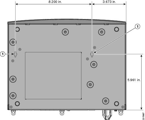
Step 1![]() Determine the required distance between mounting holes on the router. Figure 2-42 shows the wall-mount holes located on the underside of the router.
Determine the required distance between mounting holes on the router. Figure 2-42 shows the wall-mount holes located on the underside of the router.
Note![]() For most router models, the distance between mounting holes is 8.2 inches (208 mm), as shown in Figure 2-42. For the Cisco 866 and Cisco 867 models, the distance is 7.85 inches (199 mm). Verify the required distance before drilling the holes.
For most router models, the distance between mounting holes is 8.2 inches (208 mm), as shown in Figure 2-42. For the Cisco 866 and Cisco 867 models, the distance is 7.85 inches (199 mm). Verify the required distance before drilling the holes.
Figure 2-42 Wall-mount Holes on the Underside of the Router
|
|
|
Step 2![]() Insert the screws, with anchors, into the wall. Leave 1/8 inch (0.32 cm) between the screw head and the wall. See Figure 2-43.
Insert the screws, with anchors, into the wall. Leave 1/8 inch (0.32 cm) between the screw head and the wall. See Figure 2-43.
Step 3![]() Hang the router on the screw without forcibly pushing towards the wall side. The screw head may damage the protection wall inside. Place the power adapter on a nearby horizontal surface. See Figure 2-43.
Hang the router on the screw without forcibly pushing towards the wall side. The screw head may damage the protection wall inside. Place the power adapter on a nearby horizontal surface. See Figure 2-43.
Figure 2-43 Router Mounted on the Wall
|
|
|
||
|
|
|
Distance between the screw head and the wall, 1/8 in. (0.32 cm) |
Step 4![]() Connect the chassis to a reliable earth ground. For the chassis ground connection procedures, see the “Installing Cisco 890 Series in a Rack” section.
Connect the chassis to a reliable earth ground. For the chassis ground connection procedures, see the “Installing Cisco 890 Series in a Rack” section.
Installing the Router Ground Connection
The router must be connected to a reliable earth ground. Install the ground wire in accordance with local electrical safety standards.
- For NEC-compliant grounding, use size 14 AWG (2 mm 2) or larger copper wire and a ring terminal with an inner diameter of 1/4 in. (5 to 7 mm).
- For EN/IEC 60950–compliant grounding, use size 18 AWG (1 mm 2) or larger copper wire.
To install the ground connection, follow these steps:
Step 1![]() Strip one end of the ground wire to the length required for the ground lug or terminal.
Strip one end of the ground wire to the length required for the ground lug or terminal.
Step 2![]() Crimp the ground wire to the ground lug or ring terminal, using the wire crimper.
Crimp the ground wire to the ground lug or ring terminal, using the wire crimper.
Step 3![]() Attach the ground lug or ring terminal to the chassis, as shown in Figure 2-44. For a ground lug, use the two provided screws with captive locking washers. For a ring terminal, use one of the screws provided. Tighten the screws to a torque of 8 to 10 in-lb (0.9 to 1.1 N-m).
Attach the ground lug or ring terminal to the chassis, as shown in Figure 2-44. For a ground lug, use the two provided screws with captive locking washers. For a ring terminal, use one of the screws provided. Tighten the screws to a torque of 8 to 10 in-lb (0.9 to 1.1 N-m).
Figure 2-44 Chassis Ground Connection Using Ring Terminal
|
|
|
Step 4![]() Connect the other end of the ground wire to a known reliable earth ground point at your site.
Connect the other end of the ground wire to a known reliable earth ground point at your site.
After you install and properly ground the router, you can connect the power wiring, the WAN and LAN cables, and the cables for administrative access as required for your installation.
Installing the FIPS Cover
To install the FIPS cover in the router, perform these steps:
Step 1![]() Remove the four mounting screws of the top cover.
Remove the four mounting screws of the top cover.
Step 2![]() Install the left-side FIPS cover, as shown in detail A.
Install the left-side FIPS cover, as shown in detail A.
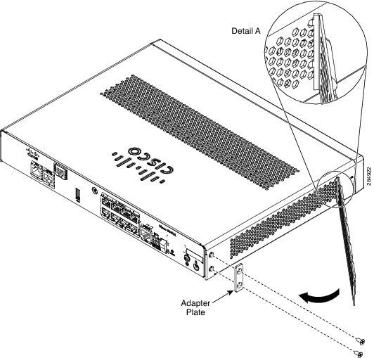
Step 3![]() Rotate and bring into the close position to hinge to the correct hexagon.
Rotate and bring into the close position to hinge to the correct hexagon.
Step 4![]() Place the adapter plate before closing by aligning the mounting holes.
Place the adapter plate before closing by aligning the mounting holes.
Step 5![]() Secure the FIPS cover with two mounting screws.
Secure the FIPS cover with two mounting screws.
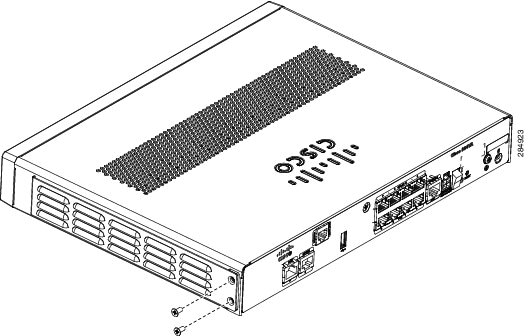
Step 6![]() Install the right-side FIPS cover the same way as the left-side FIPS cover.
Install the right-side FIPS cover the same way as the left-side FIPS cover.
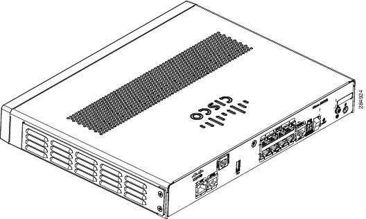
Step 7![]() View after both covers are installed.
View after both covers are installed.
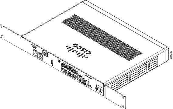
Step 8![]() If the FIPS covers are installed with the rack mount brackets, the adapter plates are not required in the installation.
If the FIPS covers are installed with the rack mount brackets, the adapter plates are not required in the installation.
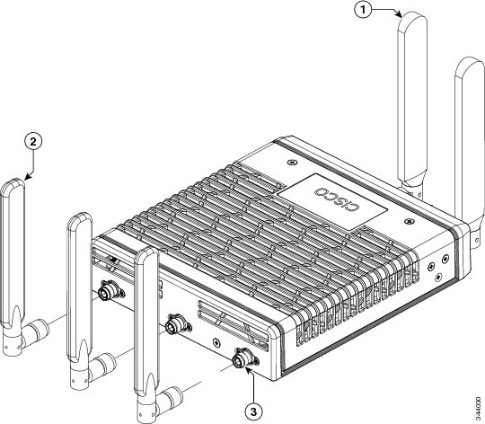
Installing Antennas for Cisco 890 Series
The Cisco 890 series wireless routers have three reverse-polarity threaded Neill-Concelman (RP-TNC) connectors on the back panel. The antennas that are shipped with the router are dual-band 2.4-GHz to 5-GHz omnidirectional dipole antennas.
Warning![]() All wireless LAN products in the 5.2/5.3GHz band cannot be used outdoors. Use the product only indoors. Statement 372
All wireless LAN products in the 5.2/5.3GHz band cannot be used outdoors. Use the product only indoors. Statement 372
Note![]() Before you install the Cisco 890 series wireless router on a table, wall, or rack, connect the antennas to the back panel. It is difficult to attach the antennas after the router is installed.
Before you install the Cisco 890 series wireless router on a table, wall, or rack, connect the antennas to the back panel. It is difficult to attach the antennas after the router is installed.
To attach the radio antennas to your wireless router, follow these steps:
Step 1![]() Manually screw the antennas tight to the RP-TNC connectors on the back of the router.
Manually screw the antennas tight to the RP-TNC connectors on the back of the router.
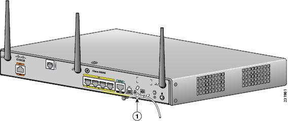
Figure 2-45 Attaching Antennas to the Router
Step 2![]() Orient the antennas. For optimum wireless performance, the antennas should be perpendicular with respect to the floor.
Orient the antennas. For optimum wireless performance, the antennas should be perpendicular with respect to the floor.
a.![]() If the router is being mounted on a desk, orient the antennas straight up.
If the router is being mounted on a desk, orient the antennas straight up.
b.![]() If the router is being mounted on a wall, orient the antennas perpendicular to the floor, as shown in Figure 2-46 and Figure 2-47.
If the router is being mounted on a wall, orient the antennas perpendicular to the floor, as shown in Figure 2-46 and Figure 2-47.
Figure 2-46 Antennas Oriented Vertically Up
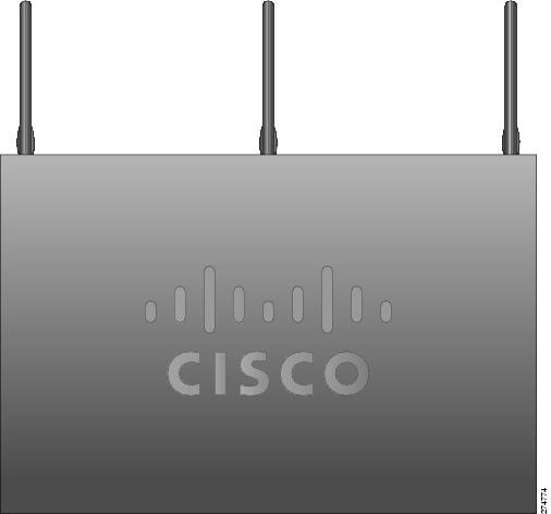
Figure 2-47 Antennas Oriented Vertically Down
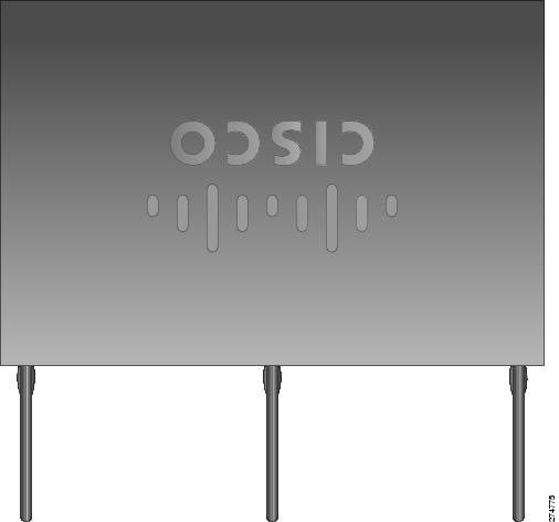
Installing Cisco 890 Series in a Rack
The Cisco 890 series ISRs can be mounted in a rack.
To install a Cisco 890 series ISR in a rack, follow these steps:
Step 1![]() Remove the screws, as shown in Figure 2-48.
Remove the screws, as shown in Figure 2-48.
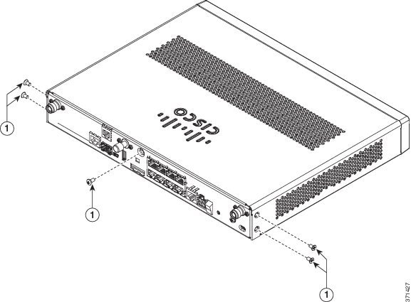
|
|
|
Step 2![]() Using the screws provided, attach the rack-mount brackets to the Cisco 890 series ISR chassis, as shown in Figure 2-49. Use two screws on each side. Use a number 2 Phillips screwdriver to install the bracket screws on both sides of the chassis.
Using the screws provided, attach the rack-mount brackets to the Cisco 890 series ISR chassis, as shown in Figure 2-49. Use two screws on each side. Use a number 2 Phillips screwdriver to install the bracket screws on both sides of the chassis.
Figure 2-49 Attaching the Rack-mount Brackets to the Cisco 890 Series ISR
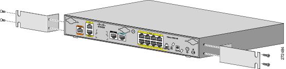
Step 3![]() Using two screws for each side (supplied with the rack), attach the Cisco 890 series ISR with rack-mount brackets to a 19-inch rack. Start with the lower pair of screws first, resting the brackets on the lower screws while you insert the upper pair of screws.
Using two screws for each side (supplied with the rack), attach the Cisco 890 series ISR with rack-mount brackets to a 19-inch rack. Start with the lower pair of screws first, resting the brackets on the lower screws while you insert the upper pair of screws.
Note![]() Be sure to leave space above and below each unit in a rack to allow for cooling air circulation.
Be sure to leave space above and below each unit in a rack to allow for cooling air circulation.
Note![]() Do not stack equipment directly above the router. Keep at least 1 rack unit of space above the router.
Do not stack equipment directly above the router. Keep at least 1 rack unit of space above the router.
Tip The screw slots in the brackets are spaced to line up with every second pair of screw holes in the rack. When the correct screw holes are used, the small threaded holes in the brackets line up with unused screw holes in the rack. If the small holes do not line up with the rack holes, you must raise or lower the brackets to the next rack hole.
Step 4![]() Place the power adapter on a nearby horizontal surface.
Place the power adapter on a nearby horizontal surface.
Step 5![]() Connect the chassis to a reliable earth ground. For the chassis ground connection procedures, see the “Installing Cisco 890 Series in a Rack” section.
Connect the chassis to a reliable earth ground. For the chassis ground connection procedures, see the “Installing Cisco 890 Series in a Rack” section.
Installing the C881G-B/S/V-K9 ISR
To install the C881G-B/S/V-K9 ISR, follow the instructions in the “Installing the Cisco 860, 880, and 890 Series Routers” section.
However, the instructions for connecting the 3G card in the hardware installation guide do not apply to the C881G-B/S/V-K9 ISR because it does not have a slot for adding a SIM card. These are CDMA/EV-DO based routers and do not require a SIM card.
Installing Antennas
For instructions on installing the antennas for the Cisco 881 routers, please refer to the “Installing Antennas” section.
Installing the C881GW-S/V-A-K9 ISR
To install the C881GW-S-A-K9 and C881GW-V-A-K9 ISRs, follow the instructions in the “Installing the Cisco 860, 880, and 890 Series Routers” section section.
However, the instructions for connecting the 3G card in the hardware installation guide do not apply because these ISRs do not have a slot for adding a 3G card. Instead, a 3G modem is embedded in the router.
Installing Antennas
For instructions on installing the antennas for the Cisco 881 routers, please refer to the “Installing Antennas” section.
Installing the C881G-U-K9 ISR
To install the C881G-U-K9 ISR, follow the instructions in the “Installing the Cisco 860, 880, and 890 Series Routers” section.
However, the instructions for connecting the 3G card in the hardware installation guide do not apply to the C881G-U-K9 ISR because it does not have a slot for adding a 3G card. Instead, a 3G modem is embedded in the router.
Installing the SIM Cards
You can install one or two SIM cards into the C881G-U-K9 ISR. Installing two SIM cards lets you take advantage of the Dual SIM feature, which provides a failover mechanism in case the primary SIM card fails.
Figure 50 shows the SIM car installation steps.
Figure 50 SIM Card Installation
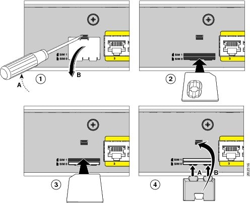
To install the SIM cards, follow these steps:
Step 1![]() Open the door covering the SIM card slots.
Open the door covering the SIM card slots.
a.![]() Insert the tip of the screw driver into the upper latch and gently disengage it as shown in the figure.
Insert the tip of the screw driver into the upper latch and gently disengage it as shown in the figure.
Step 2![]() To insert a SIM card into the SIM 0 slot, hold the SIM card with the contacts facing up as shown and gently push the card into place until it locks in.
To insert a SIM card into the SIM 0 slot, hold the SIM card with the contacts facing up as shown and gently push the card into place until it locks in.
Step 3![]() To insert a SIM card into the SIM 1 slot, hold the SIM card with the contacts facing down as shown and gently push the card into place until it locks in.
To insert a SIM card into the SIM 1 slot, hold the SIM card with the contacts facing down as shown and gently push the card into place until it locks in.
a.![]() Insert the door’s bottom latches as shown.
Insert the door’s bottom latches as shown.
b.![]() Insert the door’s upper latch into place as shown.
Insert the door’s upper latch into place as shown.
Installing the Cisco 880G for 3.7G (HSPA+)/3.5G (HSPA) ISRs
To install the C881G+7-K9, C886VAG+7-K9, C887VAG+7-K9, C887VAMG+7-K9, C888EG+7-K9, C881GW+7-A-K9, C881GW+7-E-K9, C887VAGW+7-A-K9, and C887VAGW+7-E-K9 ISRs, follow the instructions in the “Installing the Cisco 860, 880, and 890 Series Routers” section.
However, the instructions for connecting the 3G card in the hardware installation guide do not apply because these ISRs do not have a slot for adding a 3G card. Instead, a 3G modem is embedded in the router.
 Feedback