Product Overview

This chapter contains the following sections:

Introduction

The Cisco Catalyst IR1101 Rugged Series Router is a next generation modular industrial router which has a Base module with additional Pluggable Modules that can be added. The Pluggable Module provides the flexibility of adding different interfaces to the IR1101 platform.


Note


The documentation set for this product strives to use bias-free language. For purposes of this documentation set, bias-free is defined as language that does not imply discrimination based on age, disability, gender, racial identity, ethnic identity, sexual orientation, socioeconomic status, and intersectionality. Exceptions may be present in the documentation due to language that is hardcoded in the user interfaces of the product software, language used based on RFP documentation, or language that is used by a referenced third-party product.

The IR1101 also has two Expansion Modules that add key capabilities such as dual LTE Pluggables, mSATA SSD FRU, SFP, additional ethernet and async ports,and Digital GPIO connections.

The IR1101 is the first IoT platform to run the Cisco IOS-XE operating system. IOS-XE is a Linux based OS that comes with many enhancements and more features compared to the classic IOS version.

This secion of the guide also includes:
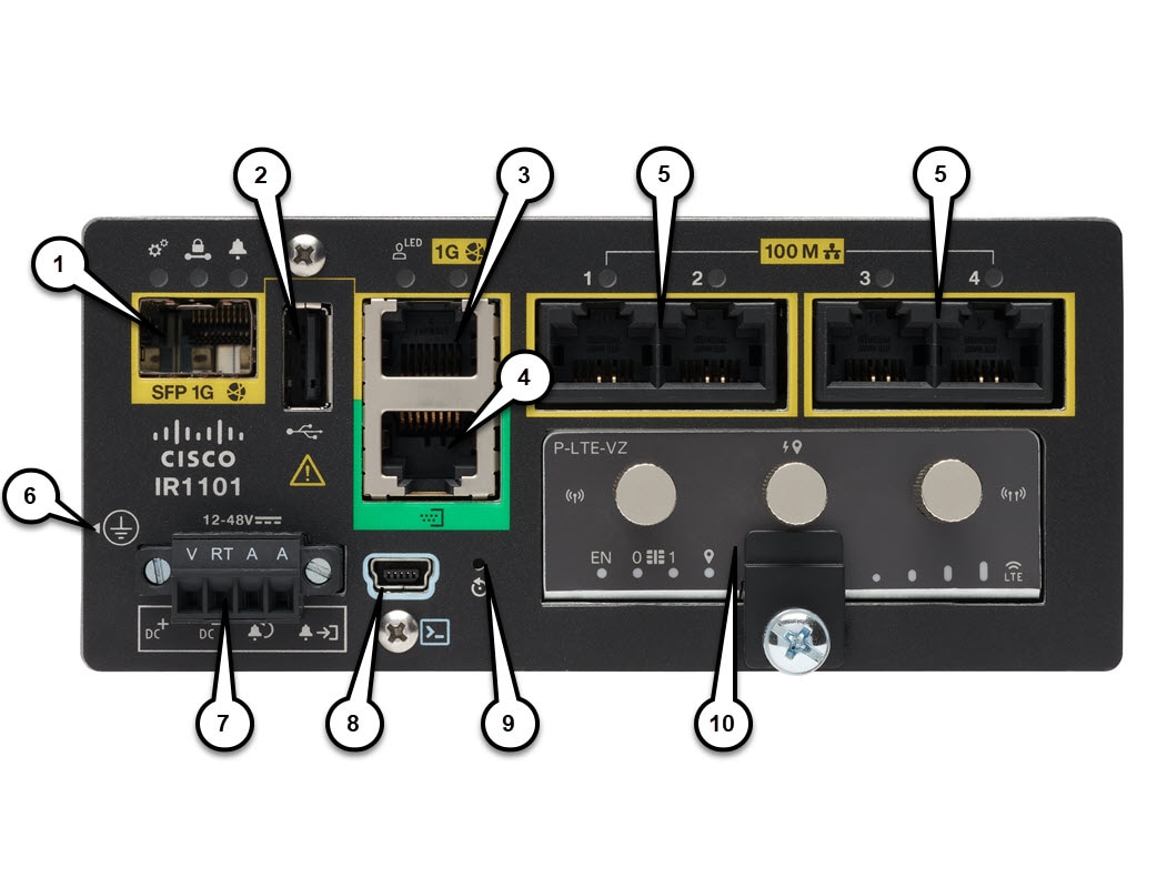
IR1101 Base Router

The following figure shows the front panel of the IR1101 and highlights some of its capabilities:

Figure 1. IR1101 Front Panel
Table 1. Front Panel Descriptions

Item

Description

1

SFP GigE WAN Port (Combo port of #3 below)

2

Type A USB 2.0 Host Port

3

RJ45 GigE WAN Port (Combo port of #1 above)

4

Asynchronous Serial Port (DTE only)

5

RJ45 Fast Ethernet LAN Ports

6

Grounding Point (On side of device)

7

DC Power and Alarm Input

8

Type B Mini-USB Console Port

9

Reset Button

10

Pluggable Module Slot (ex. 4G/LTE module)

IRM-1100 Expansion Modules

The Expansion Module comes in two types:

  • IRM-1100-SPMI

  • IRM-1100-SP

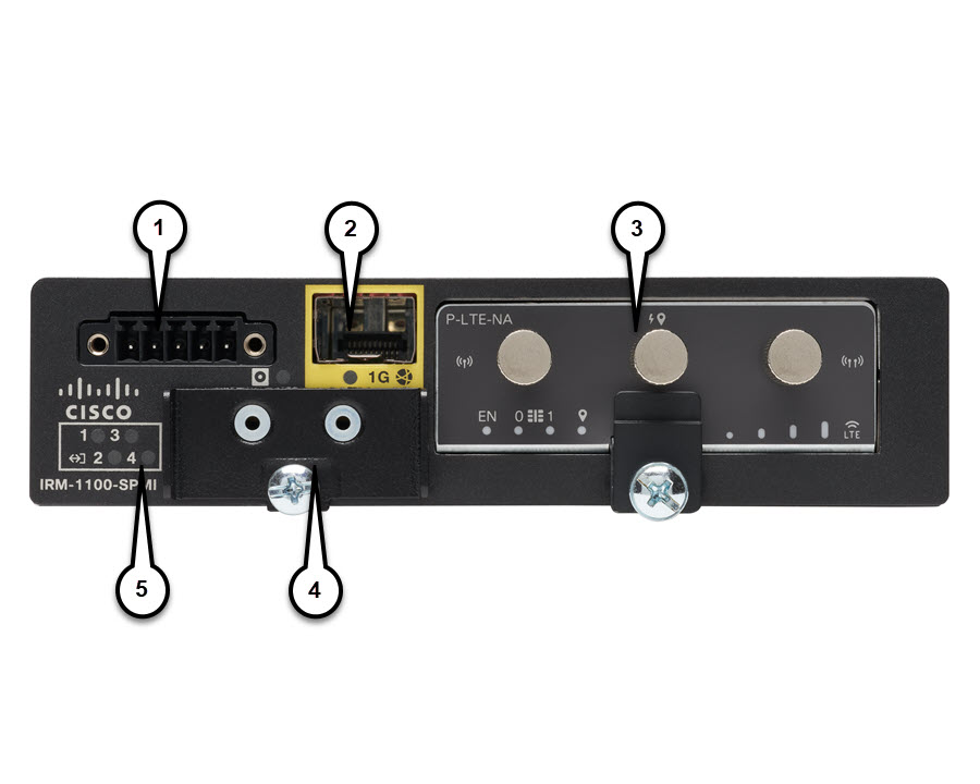
The following figure shows the front panel of the IRM-1100-SPMI and highlights some of its capabilities:

Figure 2. IR-1100-SPMI Expansion Module Details

Item

Description

1

4 GPIO + 1 Return (Digital I/O)

Note

 
Functionality is available on Cisco IOS-XE release 16.12.1 and above.

2

SFP Connector

3

Pluggable Module

4

mSATA SSD Slot

5

Digital I/O LEDs

The IR-1100-SP Expansion Module is the same as the IR-1100-SPMI module, without the Digital I/O and mSATA components.

More information can be found in IRM-1101 Expansion Module.

Complete details on the IR1101 can be found in the product data sheet.

IRM-1100-4A2T Expansion Module

The IRM-1100-4A2T is an expansion module that can be attached to the IR1101. It offers an additional four asynchronous serial ports and two Ethernet interfaces to the IR1101. The following graphic shows the IRM-1100-4A2T.

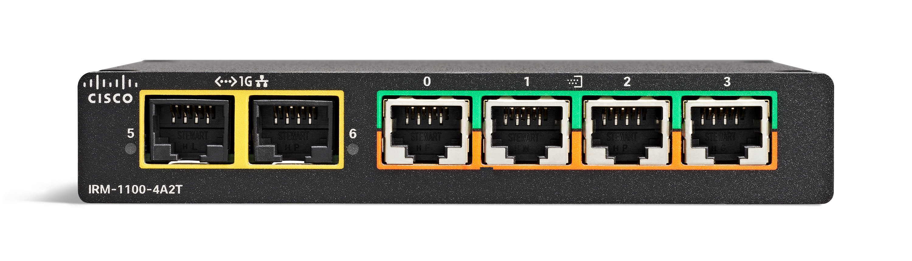
The IRM-1100-4A2T Ethernet interfaces are Layer 2 RJ45 10/100/1000 Mbps ports.

The IRM-1100-4A2T serial ports are RJ45 combo ports (RS232/RS485/RS422).

The IR1101 has two sides that expansion modules mount to. The top is called the Expansion side, and the bottom is called the Compute side. If the additional module is connected to the top, then it is referenced as the Expansion Module (EM) side. If the additional module is connected on the bottom, then it is referenced as the Compute Module (CM) side. Functionality differs depending on which side the expansion module is attached to, and how many and type of expansion modules are in use.

The IRM-1100-4A2T can be managed from the following tools:

  • Cisco DNA Center

  • WebUI

More information can be found in IRM-1100-4A2T Expansion Module.

Accessing the CLI Using a Router Console

Cisco IR1101 routers have console port with only USB support. The console cable (Cisco P/N CAB-CONSOLE-USB, 6ft long) is not included and must be ordered.

The console port is a USB 2.0 mini USB Type B connector which is located on the front panel of the chassis. The default baud rate is 9600.

If your laptop or PC warns you that you do not have the proper drivers to communicate with the router, you can obtain them from your computers manufacturer, or go here: https://www.silabs.com/products/development-tools/software/usb-to-uart-bridge-vcp-drivers

On a device fresh from the factory, you are greeted with a System Configuration Dialog where you respond to basic configuration questions. If the router was ordered for the use of Cisco PnP connect services, in the case of centralized provisioning, the router skips the initial dialog. The following is an example:

         --- System Configuration Dialog ---

Would you like to enter the initial configuration dialog? [yes/no]: yes

At any point you may enter a question mark '?' for help.
Use ctrl-c to abort configuration dialog at any prompt.
Default settings are in square brackets '[]'.


Basic management setup configures only enough connectivity
for management of the system, extended setup will ask you
to configure each interface on the system

Would you like to enter basic management setup? [yes/no]: yes
Configuring global parameters:

  Enter host name [Router]: <your-host-name>

  The enable secret is a password used to protect access to
  privileged EXEC and configuration modes. This password, after
  entered, becomes encrypted in the configuration.
  Enter enable secret: <your-password>

  The enable password is used when you do not specify an
  enable secret password, with some older software versions, and
  some boot images.
  Enter enable password: <your-password>

  The virtual terminal password is used to protect
  access to the router over a network interface.
  Enter virtual terminal password: <your-password>
Setup account for accessing HTTP server? [yes]: <return>
    Username  [admin]: <your-username>
    Password  [cisco]: <your-password>
    Password is UNENCRYPTED.
  Configure SNMP Network Management? [no]: <return>

Current interface summary

Any interface listed with OK? value "NO" does not have a valid configuration

Interface              IP-Address      OK? Method Status                Protocol
GigabitEthernet0/0/0   unassigned      NO  unset  up                    up      
FastEthernet0/0/1      unassigned      YES unset  down                  down    
FastEthernet0/0/2      unassigned      YES unset  down                  down    
FastEthernet0/0/3      unassigned      YES unset  down                  down    
FastEthernet0/0/4      unassigned      YES unset  up                    up      
Async0/2/0             unassigned      YES unset  up                    down    
Vlan1                  unassigned      YES unset  up                    up      

Note


Names and IP addresses in this next section are shown as examples.
 
Enter interface name used to connect to the
management network from the above interface summary: vlan1

Configuring interface Vlan1:
  Configure IP on this interface? [no]: yes
    IP address for this interface: 192.168.1.1
    Subnet mask for this interface [255.255.255.0] : <return>
    Class C network is 192.168.1.0, 24 subnet bits; mask is /24

Would you like to configure DHCP? [yes/no]: yes
 Enter DHCP pool name: wDHCPool
 Enter DHCP network: 192.168.1.0
 Enter DHCP netmask: 255.255.255.0
 Enter Default router: 192.168.1.1

The following configuration command script was created:

hostname <your-hostname>
enable secret 9 $9$Z6fl74fvoEdMgU$XZYs8l4phbqpXsb48l9bzCng3u4Bc2kh1STsoLoHNes
enable password <your-enable-password>
line vty 0 4
password <your-password>
username <your-username> privilege 15 password <your-password>
no snmp-server
!
!
interface GigabitEthernet0/0/0
shutdown
no ip address
!
interface FastEthernet0/0/1
!
interface FastEthernet0/0/2
!
interface FastEthernet0/0/3
!
interface FastEthernet0/0/4
!         
interface Vlan1
no shutdown
ip address 192.168.1.1 255.255.255.0
no mop enabled
ip dhcp pool wDHCPool
network 192.168.1.0 255.255.255.0
default-router 192.168.1.1
!
end


[0] Go to the IOS command prompt without saving this config.
[1] Return back to the setup without saving this config.
[2] Save this configuration to nvram and exit.

Enter your selection [2]: 2
Building configuration...

[OK]
Use the enabled mode 'configure' command to modify this configuration.


Press RETURN to get started! <return>


*Jul 27 21:35:24.369: %CRYPTO_ENGINE-5-KEY_ADDITION: A key named TP-self-signed-3211716068 has been generated or imported by crypto-engine
*Jul 27 21:35:24.372: %SSH-5-ENABLED: SSH 1.99 has been enabled
*Jul 27 21:35:24.448: %PKI-4-NOCONFIGAUTOSAVE: Configuration was modified.  Issue "write memory" to save new IOS PKI configuration
*Jul 27 21:35:24.532: %CRYPTO_ENGINE-5-KEY_ADDITION: A key named TP-self-signed-3211716068.server has been generated or imported by crypto-engine
hostname>

The device now has a basic configuration that you can build upon.

Using the Console Interface

Procedure


Step 1

Enter the following command:

Router > enable

Step 2

(Go to Step 3 if the enable password has not been configured.) At the password prompt, enter your system password:

Password: enablepass

When your password is accepted, the privileged EXEC mode prompt is displayed.

Router#

You now have access to the CLI in privileged EXEC mode and you can enter the necessary commands to complete your desired tasks.

Step 3

To exit the console session, enter the quit command:

Router# quit


Accessing the CLI from a Remote Console

The remote console of the IR1101 can be accessed through Telnet or the more secure SSH. Details on telnet access follow in this chapter. For details on SSH access see Secure Shell.

The following topics describe the procedure to access the CLI from a remote console:

Preparing to Connect to the Router Console Using Telnet

See the Cisco IOS-XE Device hardening guide at https://www.cisco.com/c/en/us/support/docs/ip/access-lists/13608-21.html for details.

Configuring the diagnostic and wait banners is optional, but recommended. The banners are especially useful as indicators to users about the status of their Telnet or SSH attempts.

To access the router remotely using Telnet from a TCP/IP network, configure the router to support virtual terminal lines using the line vty global configuration command. Configure the virtual terminal lines to require users to log in and specify a password.

See the Cisco IOS Terminal Services Command Reference document for more information about the line vty global configuration command.

To prevent disabling login on a line, specify a password with the password command when you configure the login command.

If you are using authentication, authorization, and accounting (AAA), configure the login authentication command. To prevent disabling login on a line for AAA authentication when you configure a list with the login authentication command, you must also configure that list using the aaa authentication login global configuration command.

For more information about AAA services, see the Cisco IOS XE Security Configuration Guide: Secure Connectivity and the Cisco IOS Security Command Reference documents. For more information about the login line-configuration command, see the Cisco IOS Terminal Services Command Reference document.

In addition, before you make a Telnet connection to the router, you must have a valid hostname for the router or have an IP address configured on the router. For more information about the requirements for connecting to the router using Telnet, information about customizing your Telnet services, and using Telnet key sequences, see the Cisco IOS Configuration Fundamentals Configuration Guide.

Using Telnet to Access a Console Interface

Procedure


Step 1

From your terminal or PC, enter one of the following commands:

  • connect host [port] [keyword]

  • telnet host [port] [keyword]

Here, host is the router hostname or IP address, port is a decimal port number (23 is the default), and keyword is a supported keyword. For more information about these commands, see the Cisco IOS Terminal Services Command Reference document.

Note


If you are using an access server, specify a valid port number, such as telnet 172.20.52.40 2004, in addition to the hostname or IP address.

The following example shows how to use the telnet command to connect to a router named router:

unix_host% telnet router
Trying 172.20.52.40...
Connected to 172.20.52.40.
Escape character is '^]'.
unix_host% connect

Step 2

Enter your login password:

User Access Verification
Password: mypassword

Note


If no password has been configured, press Return.

Step 3

From user EXEC mode, enter the enable command:

Router> enable

Step 4

At the password prompt, enter your system password:

Password: enablepass

Step 5

When the enable password is accepted, the privileged EXEC mode prompt is displayed:

Router#

Step 6

You now have access to the CLI in privileged EXEC mode and you can enter the necessary commands to complete your desired tasks.

Step 7

To exit the Telnet session, use the exit or logout command.

Router# logout

CLI Session Management

An inactivity timeout is configurable and can be enforced. Session locking provides protection from two users overwriting changes that the other has made. To prevent an internal process from using all the available capacity, some spare capacity is reserved for CLI session access. For example, this allows a user to remotely access a router.

Information About CLI Session Management

An inactivity timeout is configurable and can be enforced. Session locking provides protection from two users overwriting changes that each other has made. To prevent an internal process from using all the available capacity, some spare capacity is reserved for CLI session access. For example, this allows a user to remotely access the router.

Changing the CLI Session Timeout

Procedure


Step 1

configure terminal

Enters global configuration mode

Step 2

line console 0

Step 3

session-timeout minutes

The value of minutes sets the amount of time that the CLI waits before timing out. Setting the CLI session timeout increases the security of a CLI session. Specify a value of 0 for minutes to disable session timeout.

Step 4

show line console 0

Verifies the value to which the session timeout has been set, which is shown as the value for " Idle Session ".

Locking a CLI Session

Before you begin

To configure a temporary password on a CLI session, use the lock command in EXEC mode. Before you can use the lock command, you need to configure the line using the lockable command. In this example the line is configured as lockable, and then the lock command is used and a temporary password is assigned.

Procedure


Step 1

Router# configure terminal

Enters global configuration mode.

Step 2

Enter the line upon which you want to be able to use the lock command.

Router(config)# line console 0

Step 3

Router(config)# lockable

Enables the line to be locked.

Step 4

Router(config)# exit

Step 5

Router# lock

The system prompts you for a password, which you must enter twice.
Password: <password>
Again: <password>
Locked